

JerryTodd
-
Posts
790 -
Joined
-
Last visited
Content Type
Profiles
Forums
Gallery
Events
Posts posted by JerryTodd
-
-
She has turn from a piece of wood into a Beautiful looking ship. Excellent work. Thank you for sharing this with all of us.
Actually, this one was closer to turning a roll of tape into a ship

Thank you
-
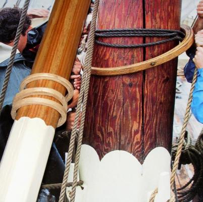
Black iron bands may not refer to color, but to the use of black iron.
Wouldings would need to be tarred
-
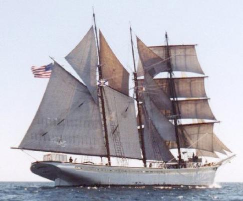
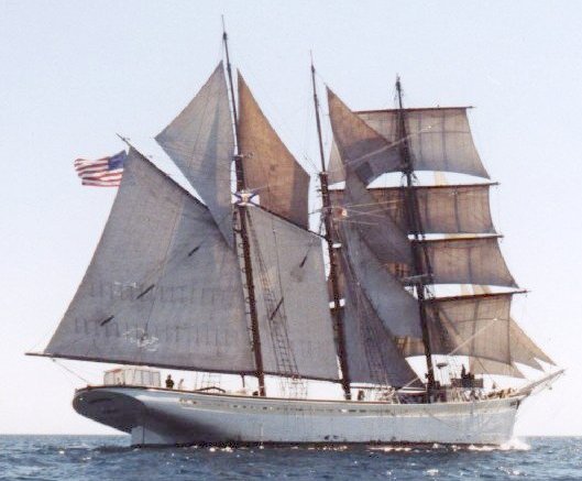
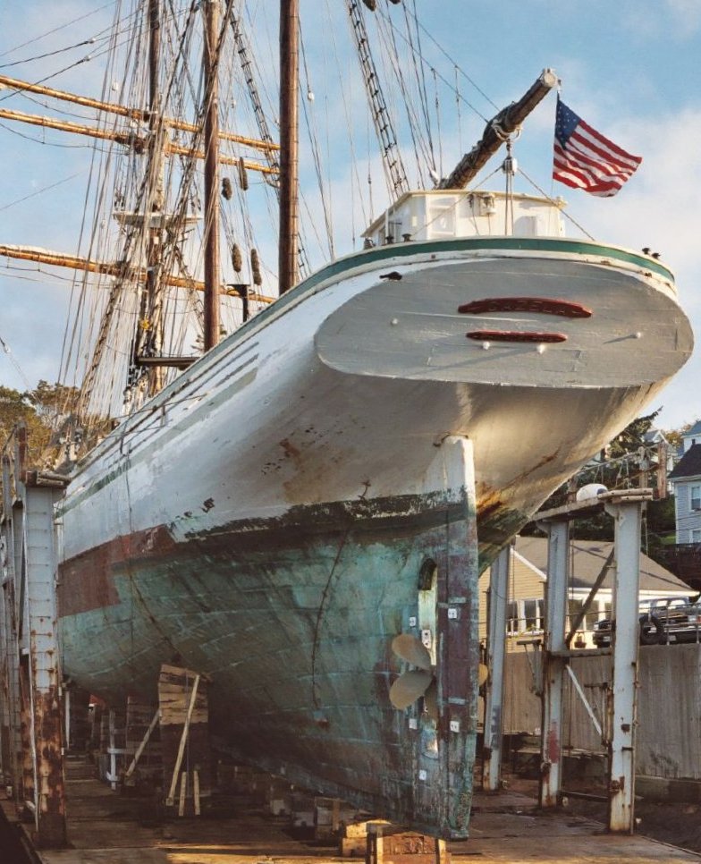
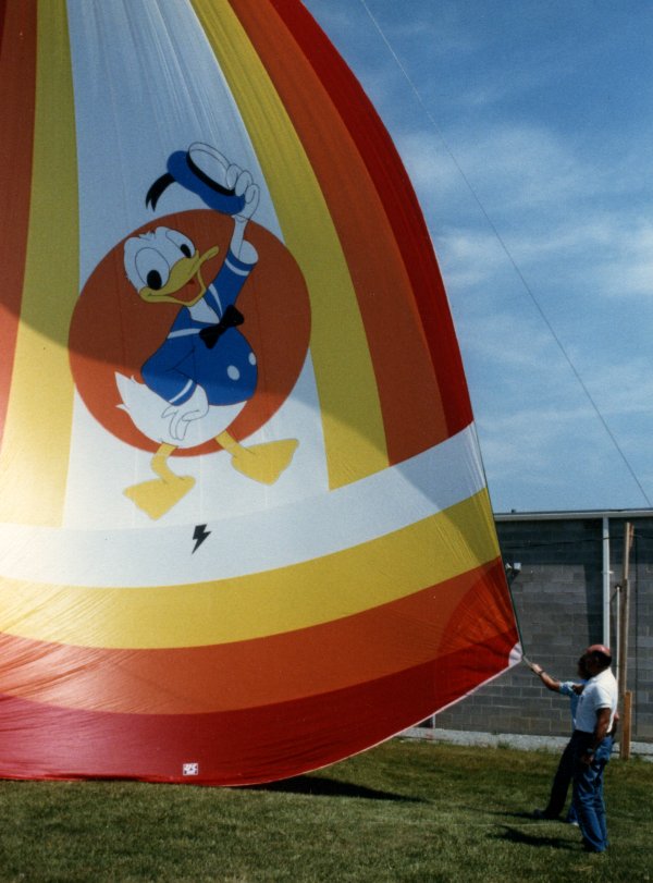
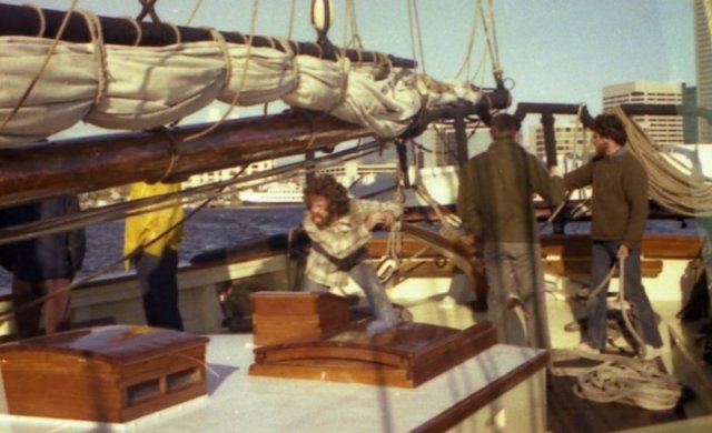
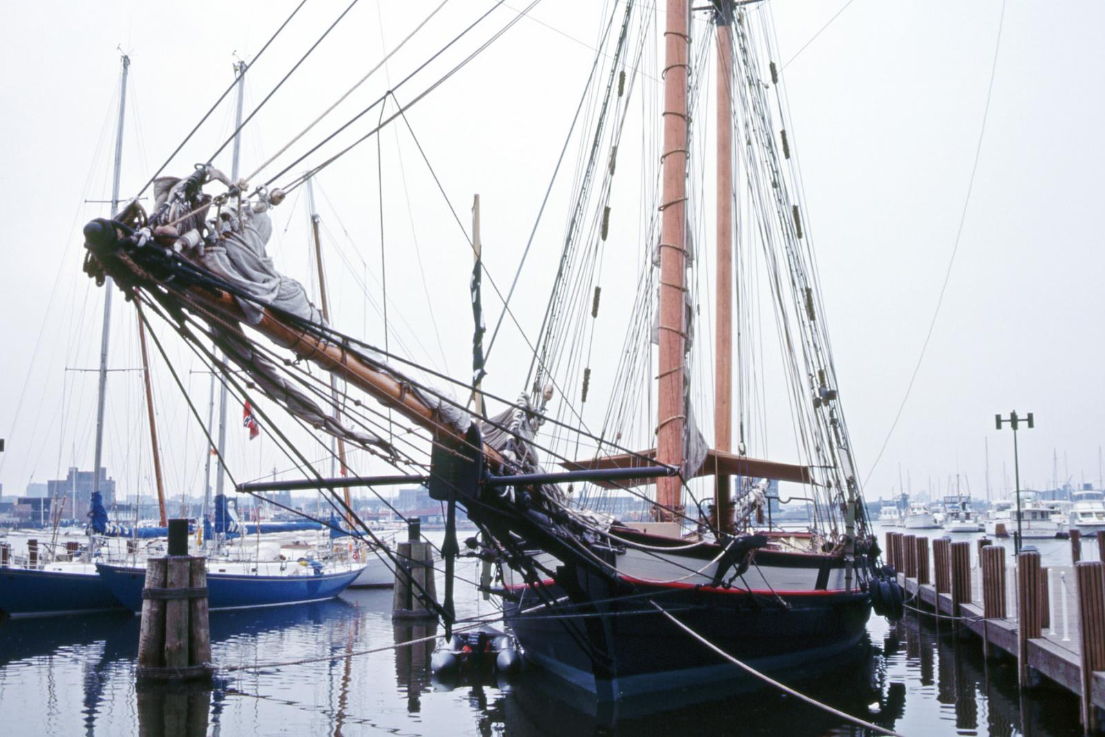
Way back in 1978 and 1979 I had the privilege of crewing on board an old Portuguese Grand Banks fishing vessel turned sail training ship, the barkentine Gazela Primeiro. Of all the boats I sailed for pay or pleasure, Gazela is my favorite and my fondest memory. It was a combination of a sturdy and trust-worthy vessel combined with a crew of wonderful people; that made me feel at home and safer than any other boat I've known.
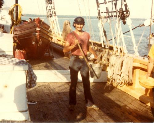 <= an 18 year old me after morning wash-down on Gazela.
A bit of the ship's history is available on My site.
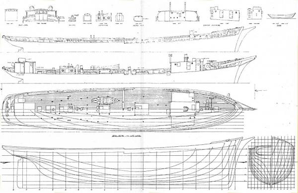
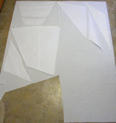
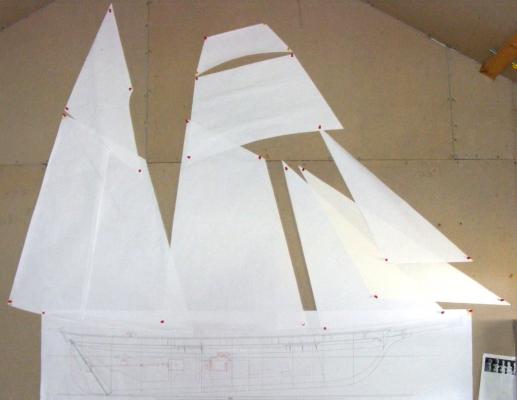
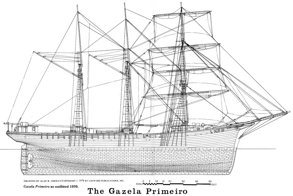
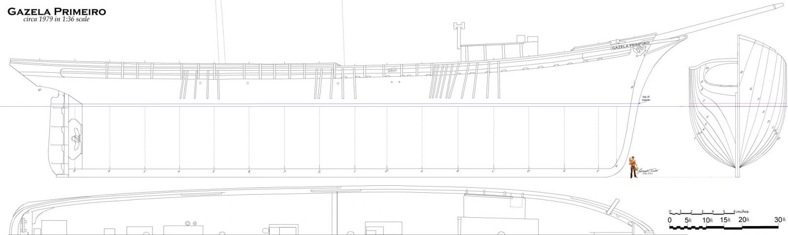
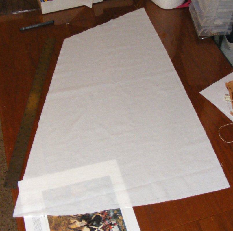
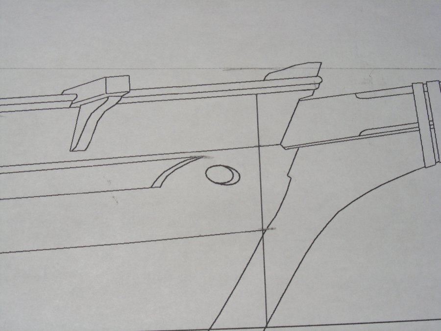
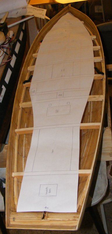
I've always dreamt of building a model of Gazela but I could never find her lines. I spent a lot of time searching, contacting people like the builder of the model in Philadelphia. Six sheets of plans were drawn up around the time I had sailed her and a profile from that set was included in a book by Allison Saville about the ship.

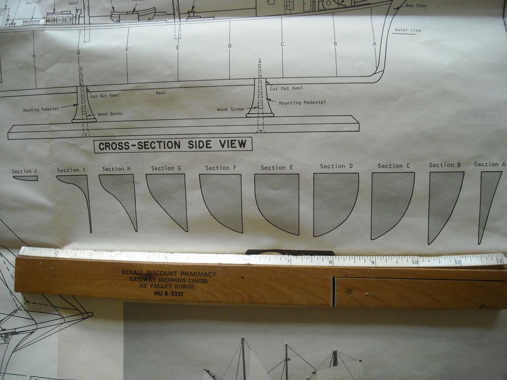
This was printed on a tabloid sized sheet, and while not perfect, was usable, but I still didn't have a body plan. One contact had built an old Scientific kit of the boat and still had the instruction sheets. He photo graphed these for me.
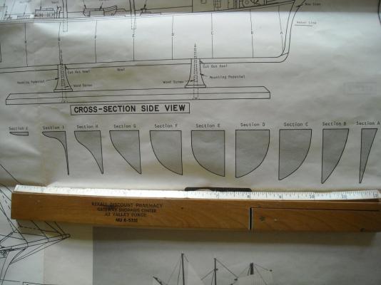
Another contact who had the plans, sent me a a paper photocopy on a tabloid sized sheet.
I scoured the Internet for any images of the boat I could find, especially those of her hauled out of the water.

I tried to reconcile what I had to each other to come up with a working set of plans in the 1:36 scale I wanted. It was very tedious with all the photography and scanning distortions.
I was getting near to something I could use, but wasn't there yet.
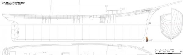
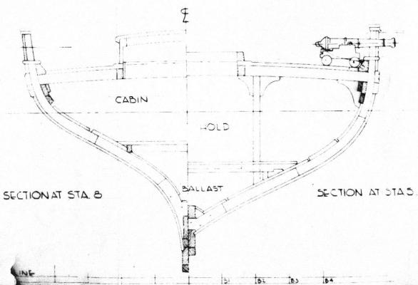
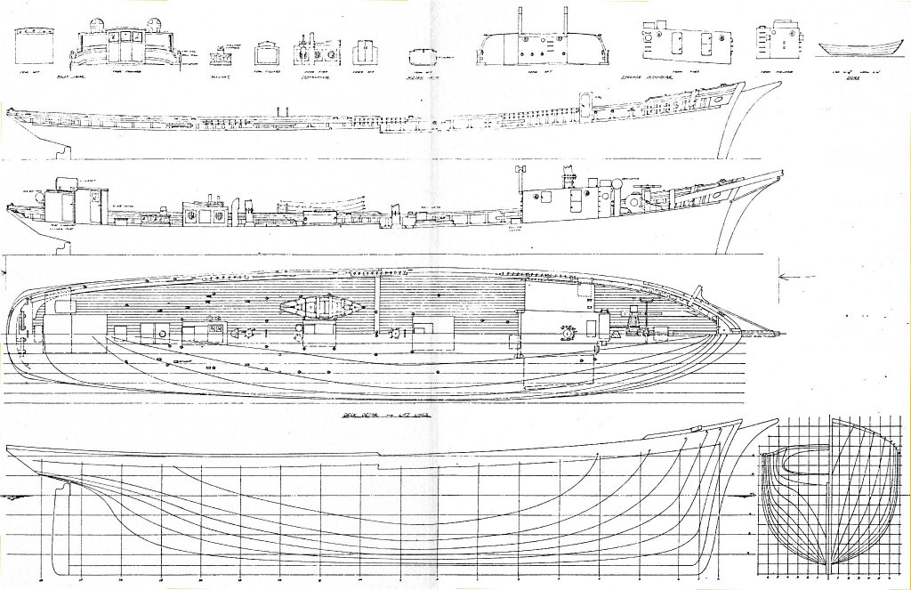
I eventual found the plans drawn up in the 70's at Mystic Seaport. They were very expensive, but I set my teeth and ordered them, only to hear they they were restricted in making copies. They steered me towards the Independence Seaport Museum who apparently hold the originals.
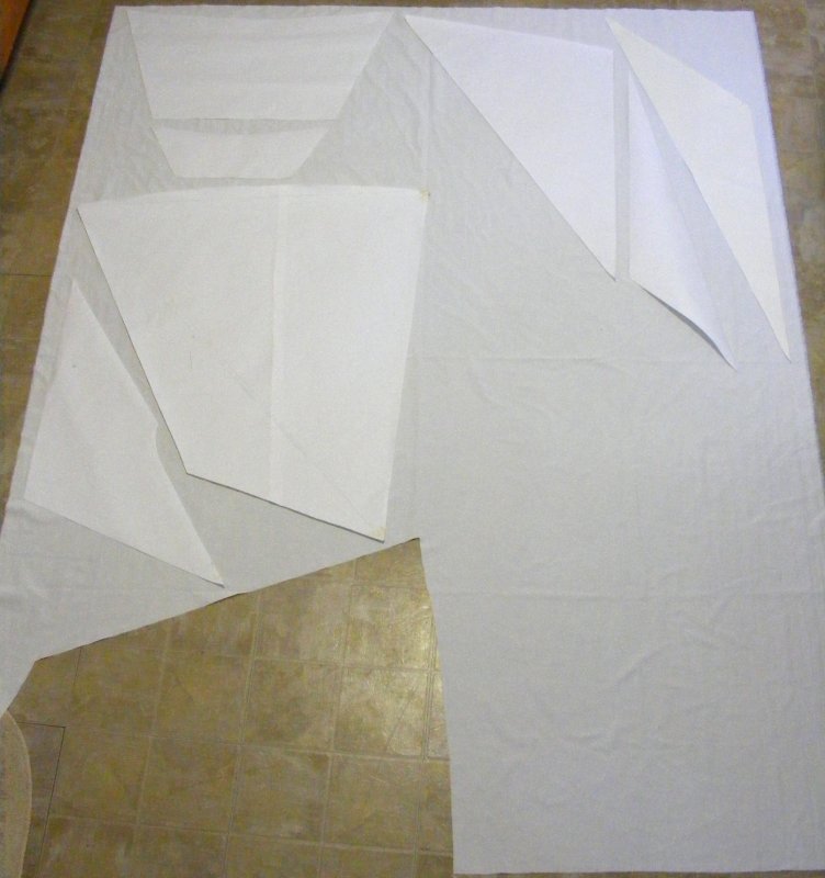
These folks are not set up to provide copies of plans. They offered to digitally photograph the plans for me, or send them out to be digitally scanned. The cost they estimate for that would be astronomical. In trying to get across what I'm after, they told me the plans were missing! Since then they've found two of the six sheets and sent sample photos; they are the same two sheets I show you above.
At this moment, I'm still negotiating with the Museum to get usable copies of Gazela's plans. If this doesn't work, I'll have to resort to my make-do attempt detailed above. -
I wonder how many captains would invest the time to paint the mast bands a different color to serve no purpose other than it looks nice, especially in war time? In peace time, I can easily see a captain keeping his crew from being idle with such chores. In the 1860's Constellation's captain regularly had the copper scrubbed, paint above and below, and rigging rerove. He even had the gun stripe painted out, and a month later repainted back on.
While that was wartime, Constellation was in the Mediterranean cruising between Italy and the Levant "showing the flag" and not much more - there was a LOT of idle time.
-
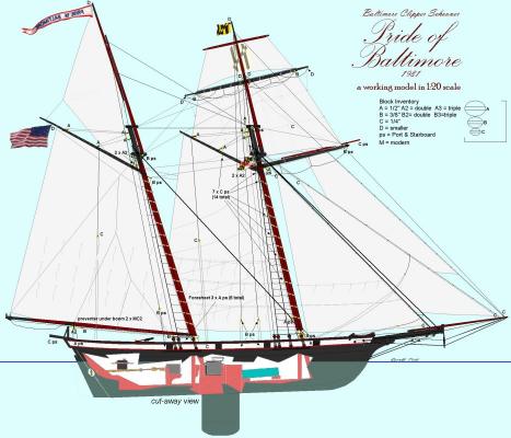
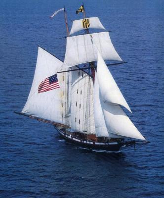
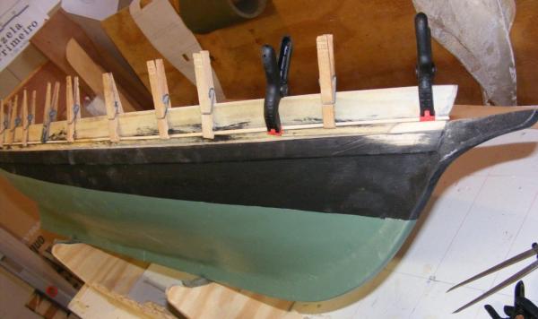
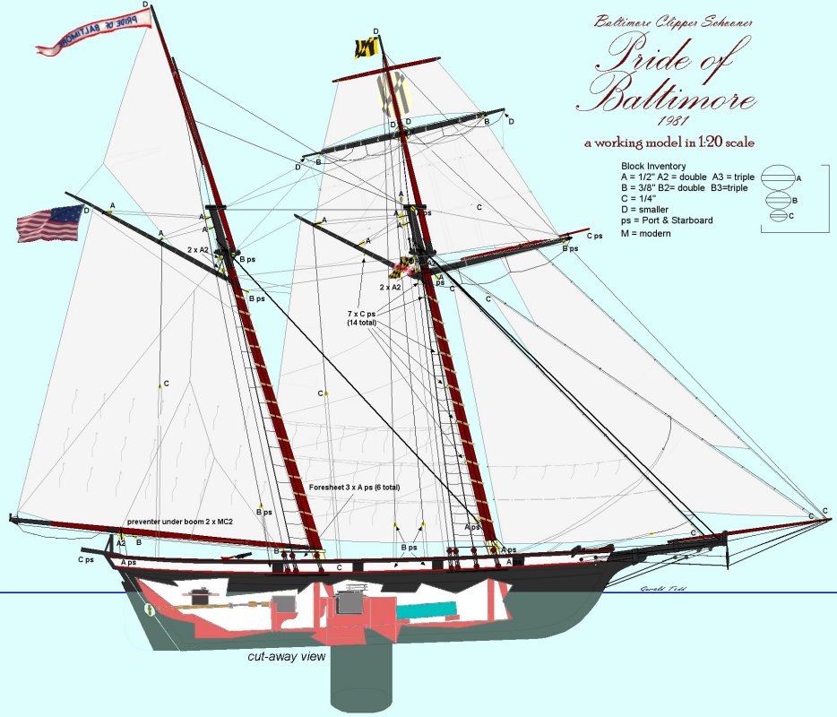
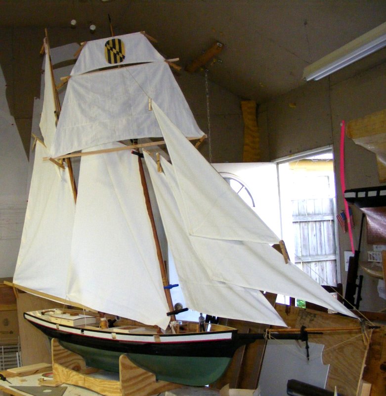
I was asked to bring the model to the Fell's Point Maritime Museum in Baltimore on July 22nd, 2012, for a one day display to commemorate the anniversary of the first 7 letter of marque vessels to sail out of Fell's Point for the War of 1812. It wasn't possible for me to fully complete the model in time, or even get it sailable, but I resolved to do as much as I could to make her presentable for display. The Pride of Baltimore II would be there, and I had sailed on Pride with her captain, Jon Miles, ie: someone intimately familiar with the boat I was modeling would see it, but hey, no pressure.
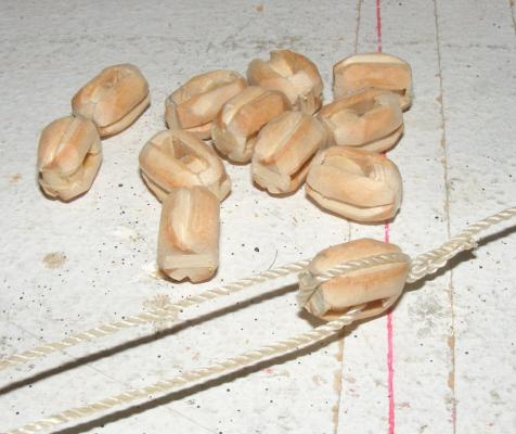
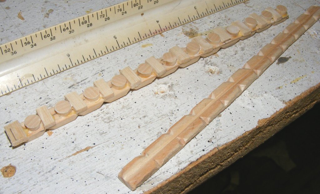
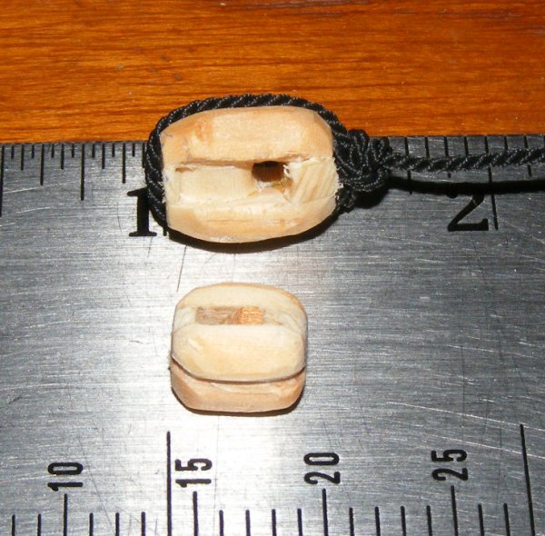
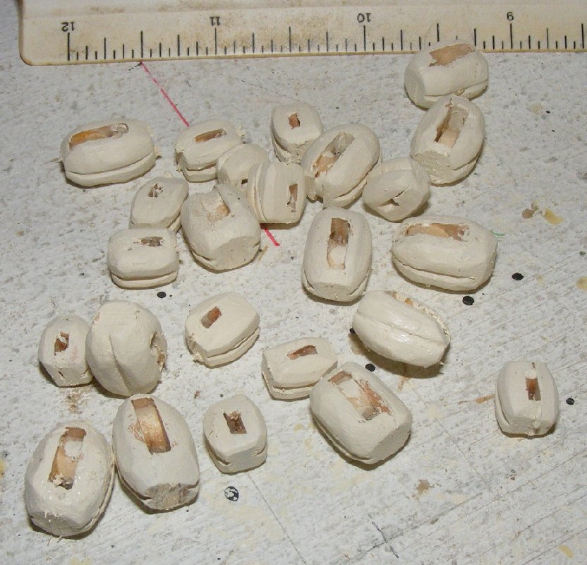
In preparation though, I bolt-roped all the sails, worked out a chart of what rigging blocks she would need, and began making them.
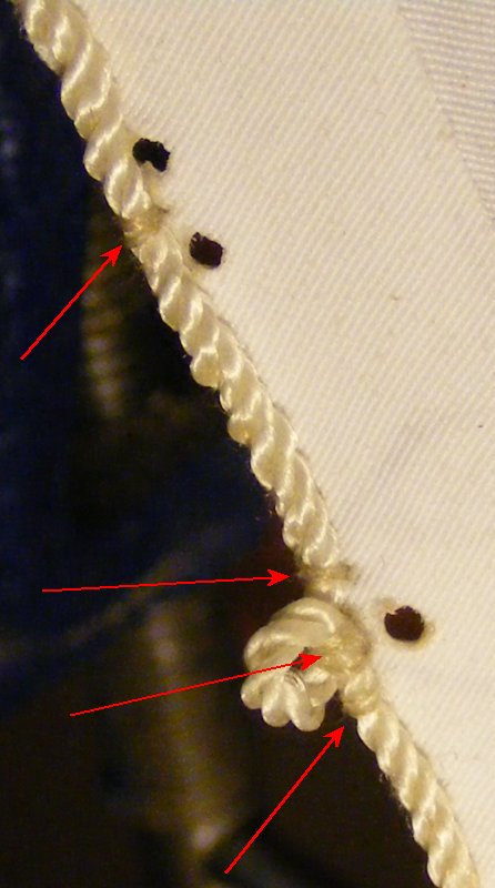
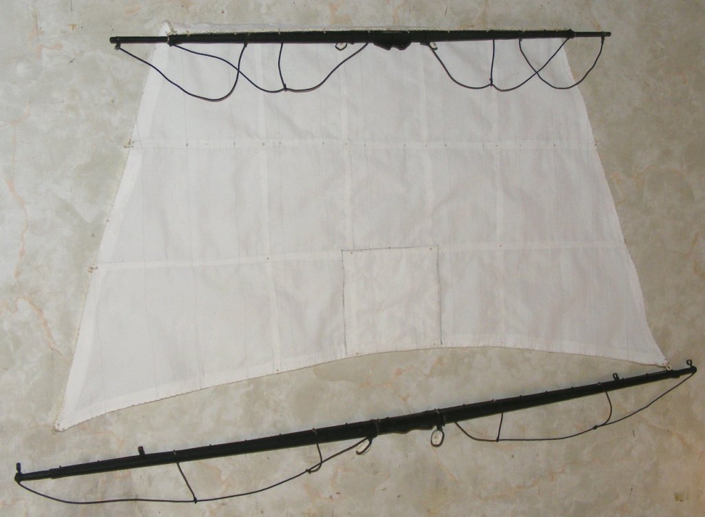
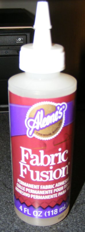
The sails are roped with a three-stranded nylon cord. The bolt rope is glued to the sail with fabric glue as well as sewn in an abbreviated version of the way real ones are sewn on. A bolt rope isn't sewn the the edge of a sail, but rather to one side of it right at the edge. Each stitch passes between two strands of the line, through the third, and into the sail, where it takes a turn back around and repeats in the next strand. Each turn is in the direction of the lay of the line sew the stitching disappears into the lay of the bolt rope. In stead of every strand, I stitched through every three or four strands. The stitching is somewhat visible at this scale, especially on the "back-side" of the sail from the bolt rope, but the glue makes up for the reduced structure.
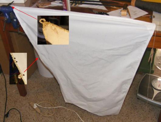
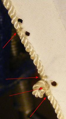
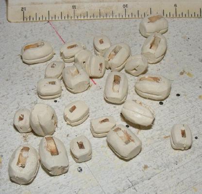
Eyes, cringles, garnets, etc, along the edge of the sail were made with the bolt rope. grommets in the sail are burned with the pointed tip of a soldiering iron. This is a nice feature of using Supplex, holes can be made for reef-points, for example, that are heat sealed and require no further reenforcing. Eyes are formed around a round toothpick to maintain constant size and keep the from closing while sewing's in progress. Grommets are burned in near each eye for and the bolt rope is seized on either side, just as a real sail is constructed. Well, this IS a real sail, just a small one. By-the-way, did I mention I used to work at Ulmer Kolius sail makers near Annapolis? I didn't usually sew on bolt ropes there, that I learned working on boats such as Pride; at Ulmer I did things like putting ducks on Flashers (a genoa/spinnaker hybrid).

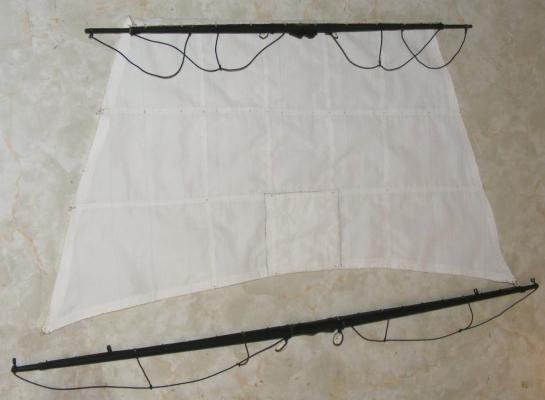
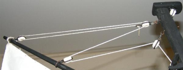
The yards got foot-ropes and I made some unsheaved blocks to cover for this display.


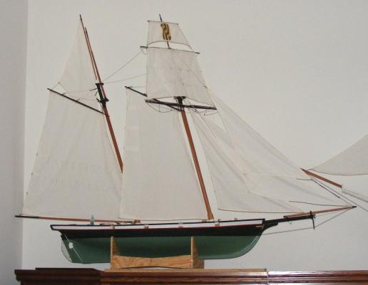
The sails were attached to their spars, the main and fores'l to the mast hoops, Halyards rove, and bit by but, Pride was dressed.
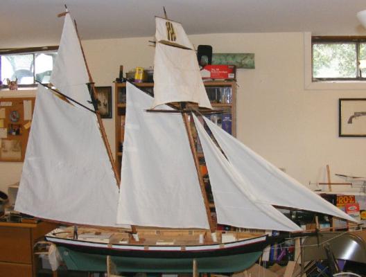
I was ready. I even cobbled together a slide show of the models construction and loaded it onto an e-frame, and made up some hand-outs with specs on the model and the real Pride.
Unfortunately, the events schedule was changed to a day I would be out of town for something else - so Pride didn't get publicly displayed.
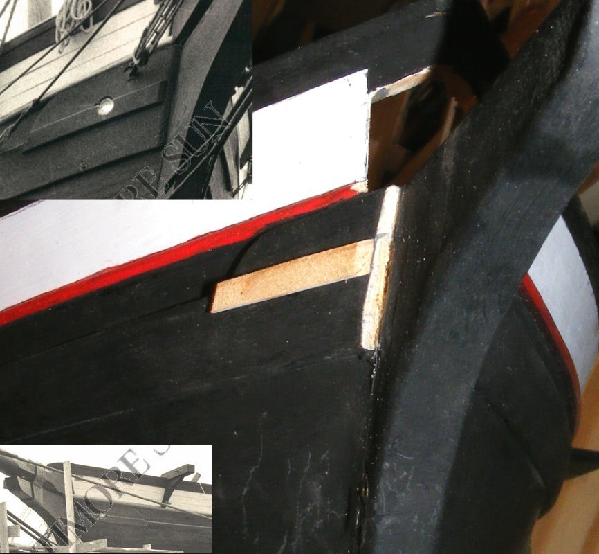
Later, I made and attached fairleads to the fore tops'l for the bunt-lines which I made from a bamboo chopstick. I found the new information on the pump heads mentioned previously. And noted a sort of rub rail under the hawse pipes of the original boat and a difference in how the wale finished at the bow.

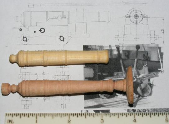
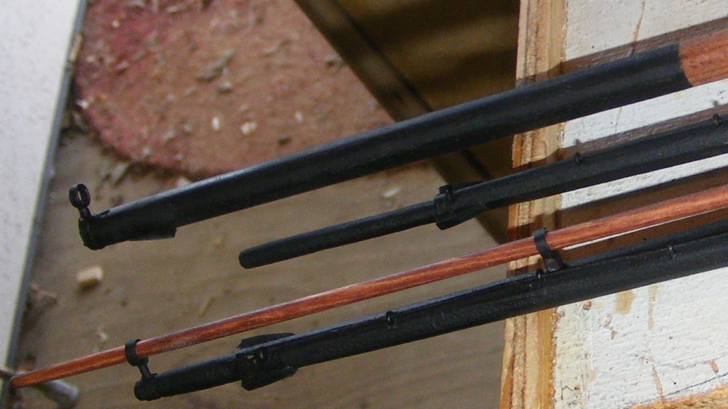
I took a shot at turning a gun barrel, one in pine, one in cherry - neither of which I'm satisfied with. The carriage was better, but I had to draw scaled plans as Gilmer's drawings of the guns were a bit cartoonish.
The model's been moved to my new residence, as I move out of my house. With no consistent income since being fired in January 2012, after 18 years, the house is being foreclosed on.
For the moment, Pride sits on top of a cabinet in the living room waiting for the new shop to come online.
-
Wow, is it that time already? Thank you
-
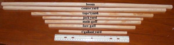
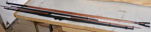
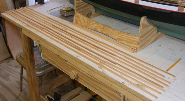
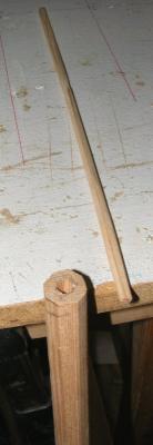
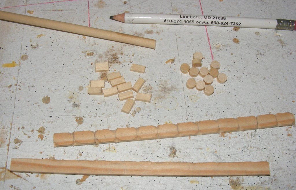
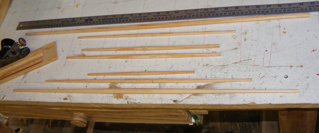
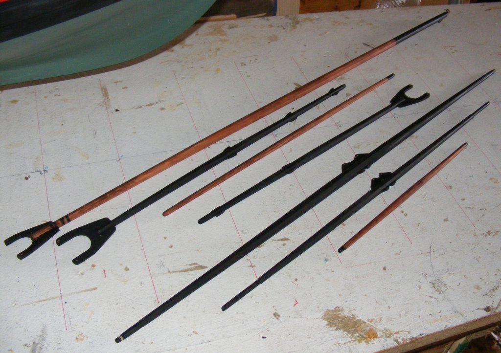
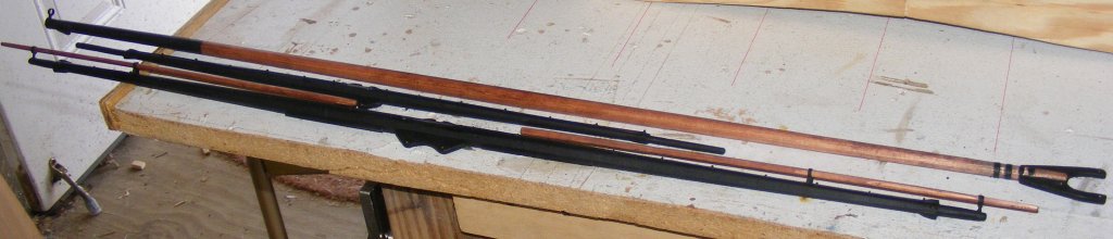
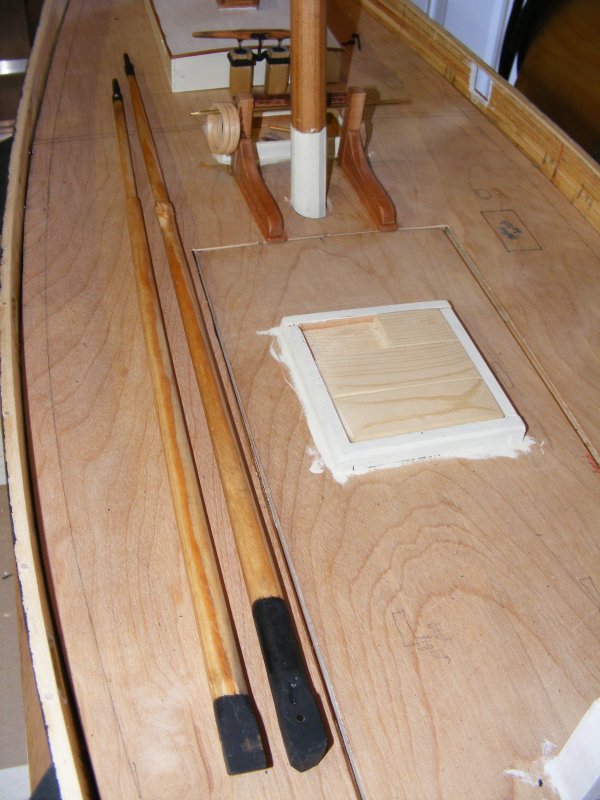
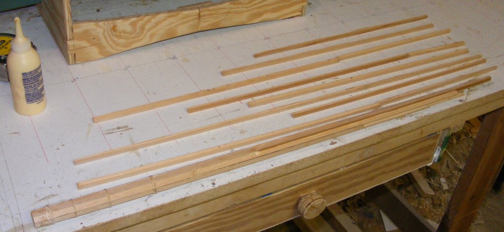
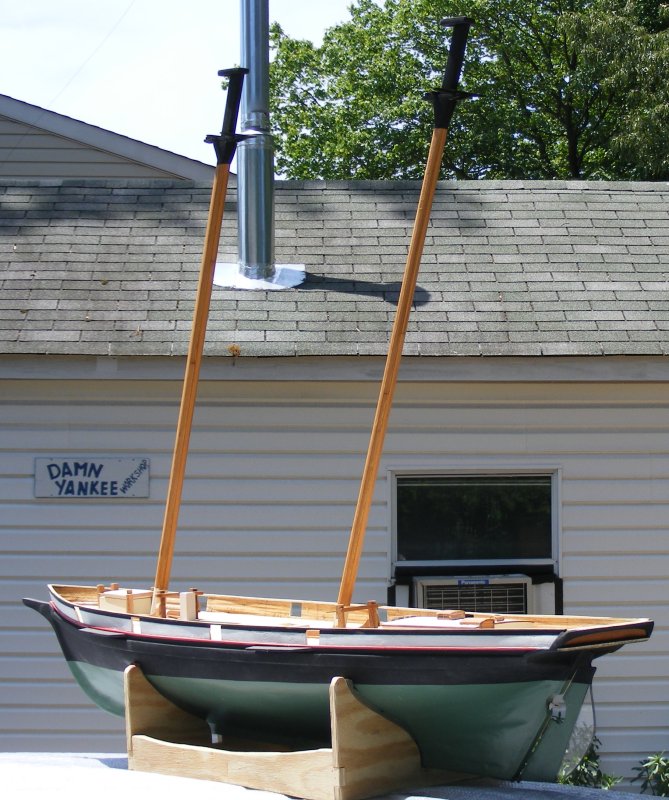
Spars
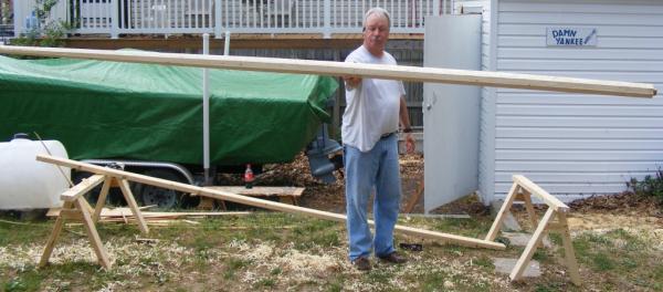
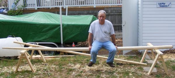
All the spars were made of white pine, since it's been working so well so far.
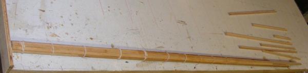
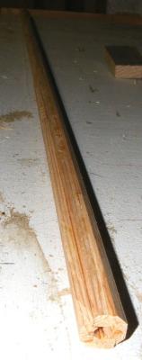
Rough cut to size, square stock was made 8-sided, etc, etc, to round.

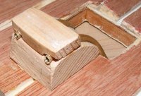
Gaffs and boom were fitted with jaws made from aircraft plywood and tried for size.
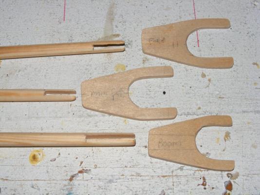

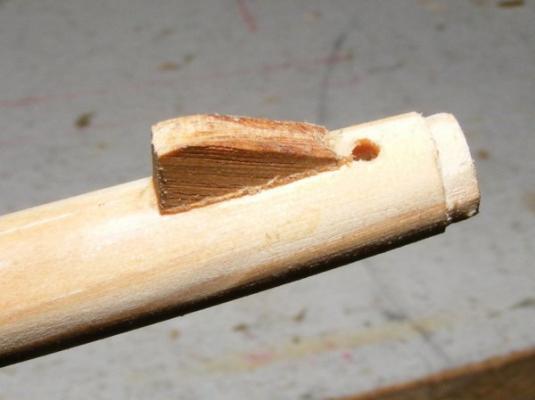
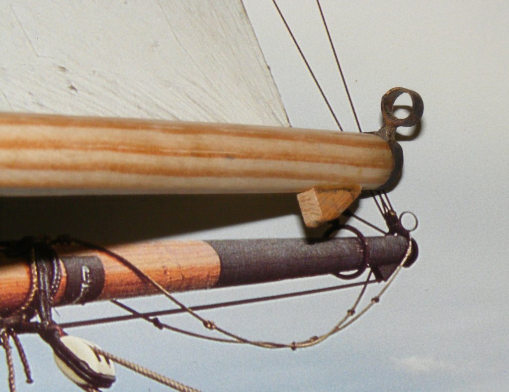
The boom has a shoulder cut in the end for the ring-tail iron and a bolster that keeps the mains'l clew out-haul held off the boom.

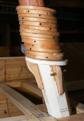
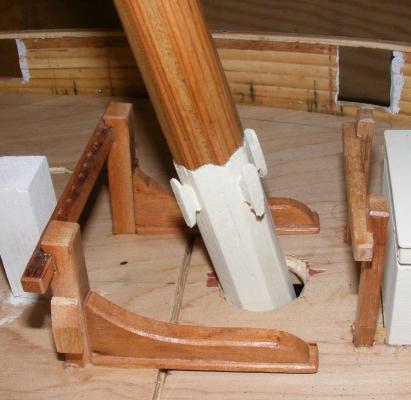
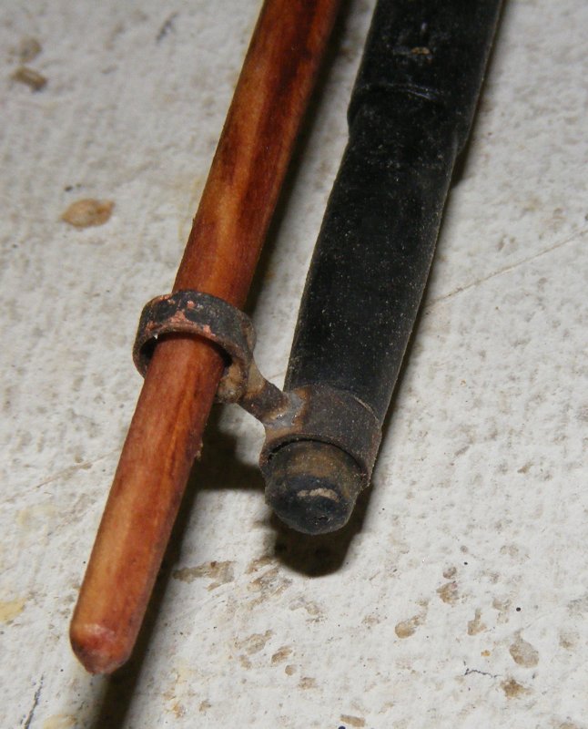
The main mast was fitted with a saddle and knees for the boom to rest on, after the mast's hoops were loaded on.
All the spars got stain and paint, and all the brass was blackened and painted. The coarse yard got stuns'l boom irons, stuns'l booms, and jack stays.

Cleats and holes for sheets and the like...
and a clew iron for the main boom
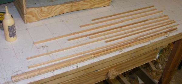
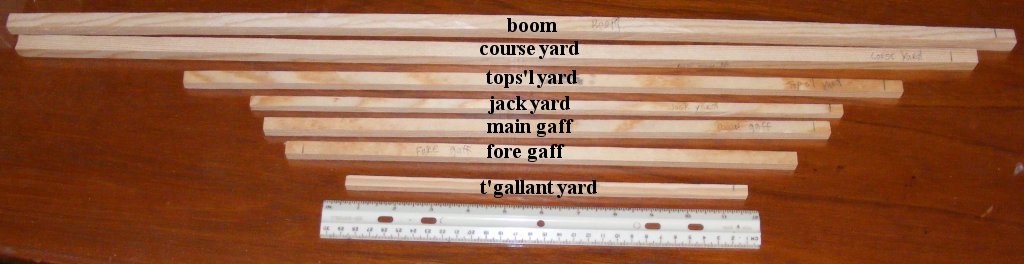
The yards and boom
-
-
BTW folks: Don't forget you can click on the images in these posts to see them full sized.
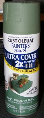
I took Pease's book to the local hardware megastore and had thier paint department use their color gizmo to create a sample jar of the cream color Pride's inboard things were painted; the sides of the cabin, hatch coamings, base of the masts, and eventually, inside of the bulwarks. This ran about $3 US and I should be able to get the color matched easily if I need more. It's funny actually, both the real boat and my model of her will have their inboard surfaces painted with latex house paint.
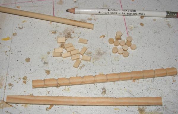
I wondered about what to make mast hoops from. I liked bamboo, but I didn't have any that wouldn't require a lot of work just to get into the right sized strips. Just for giggles, I tried 3/32" sheet bass. Cut it into a strip the right width; shaved the ends down so they tapered to nothing; wet it in warm water; and wrapped it around a 1" dowel.

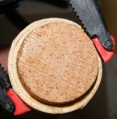
That worked so well I tried another and made a few.
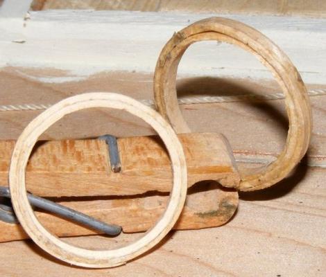
Then I precut all the rest of the strips plus a few, cause a couple snapped while wrapping them around the dowel.

Once made and glued up, I dipped them in oak stain.

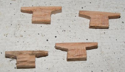
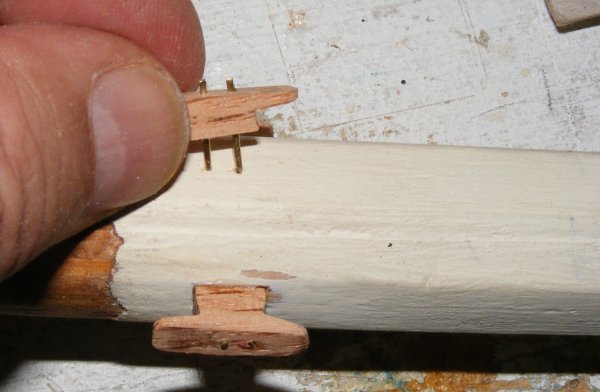
I made the cleats that go at the base of the foremast. They were glued and pinned on - after loading the mast with it's requisite number of hoops.
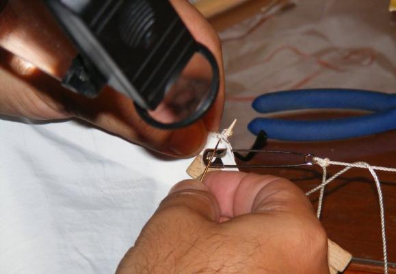
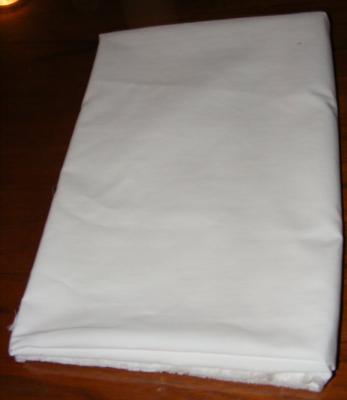
Two weeks before, a couple of yards of Supplex arrived for the sails. When I cut out Constellation's sails, it was a pain. To seal the edge of the after cutting it I would run it along a hot soldering iron. It didn't take much, just the slightest pause, to burn a scallop in the edge.
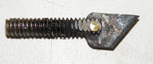
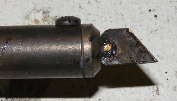
This time I resolved to use a hot knife. Oddly, I had a very hard time finding one for my iron, so I made one.
I happened to have a couple of copper machine screws in my loose fastener bucket that had the right threads to fit my soldering iron. I drilled a hole, then cut a slot and inserted a portion of an XActo blade. I pressed the slot closed onto the blade and peened a bit of brass rod in the hole to rivet it all together.

The first sail I cut with it was the mains'l, and it worked like a charm. There's a little technique to it, but you pick it up fast. When I was researching making one online, everyone said it's best to cut on glass so as to not wick the heat off the blade, so I used an old picture with glass in the frame as my cutting board.
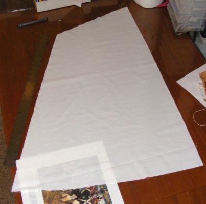
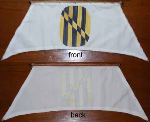
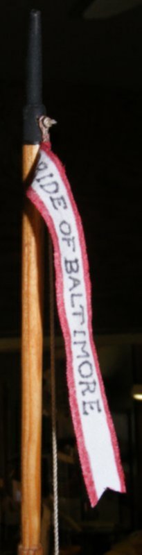
I had the knife made on June 2nd, and laid out and cut the rest of the sails by June 3rd. I even made Pride's pennant and that ugly Lord Baltimore eblem they had on the t'gallant sail.

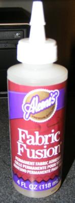
The panels were marked on the cloth with a very fine point black marker, just as I had done on Constellation. Other parts of the sails were cut with the knife; reef bands, tabling, corner reenforcing, that ugly emblem, etc. These were applied to the sail with fabric adhesive.

- Duanelaker, pollex, yvesvidal and 6 others
-
 9
9
-
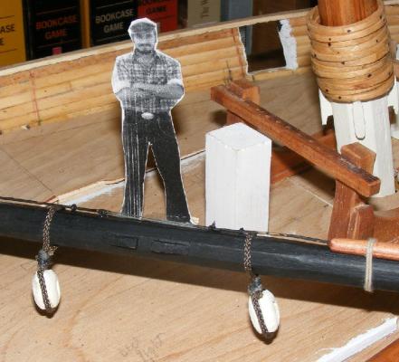
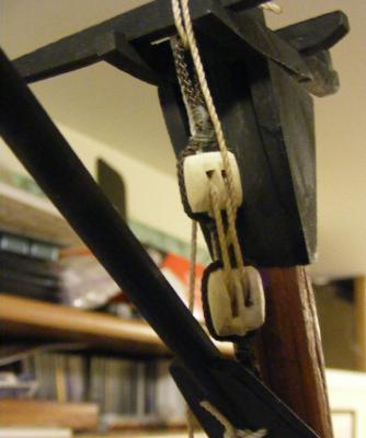
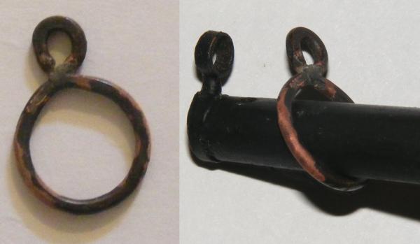
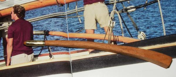
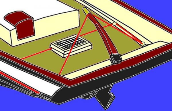
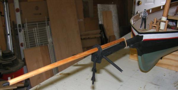
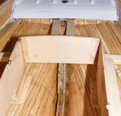
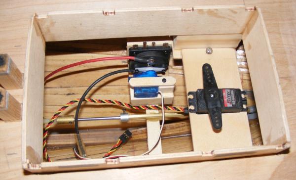
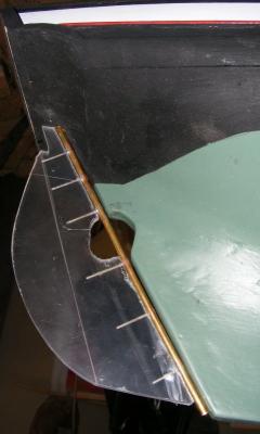
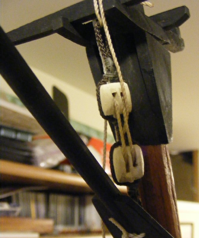
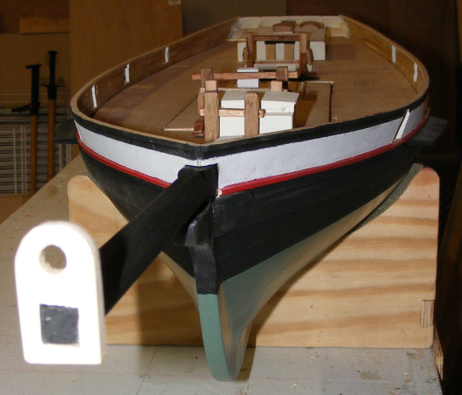
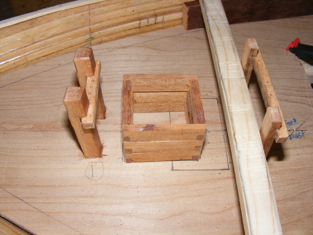
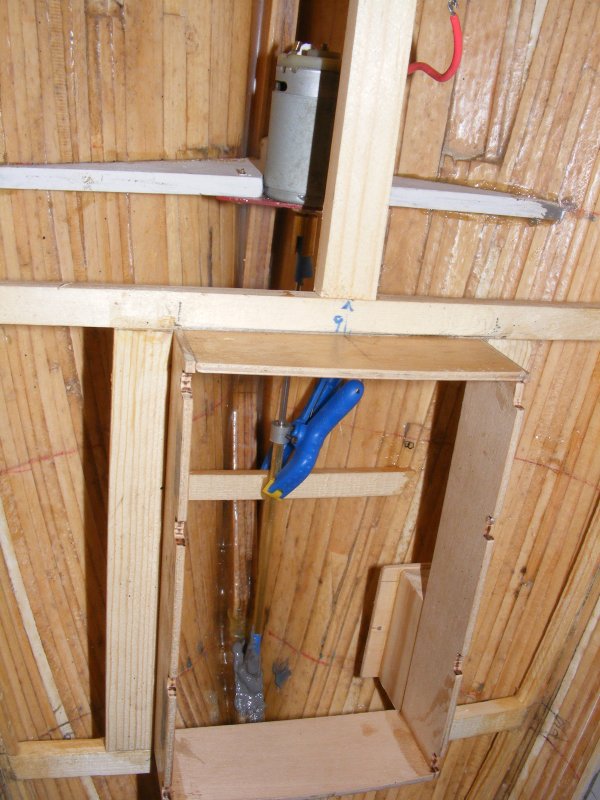
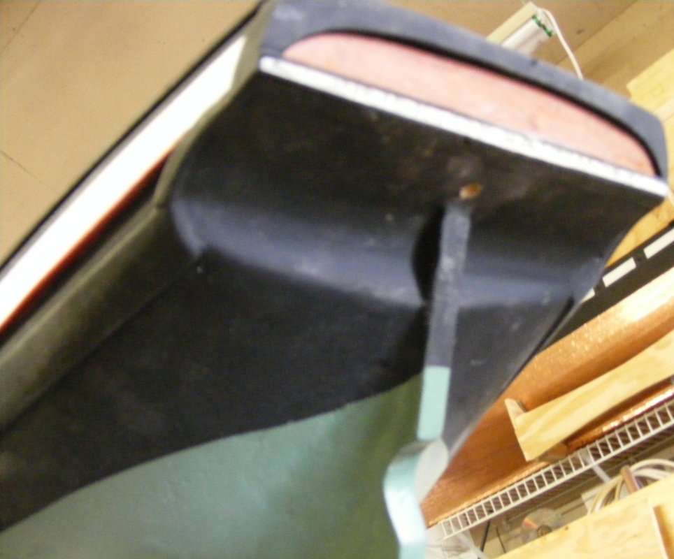
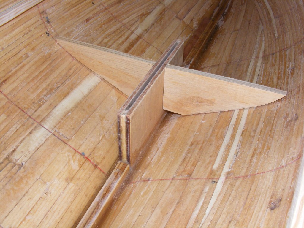
As shown above, there's no space in the counter to install linkages for steering the model remotely that wouldn't be glaringly noticeable and intrusive, so, another way to steer the model had to be devised. The real boat was steered by a tiller. Some 8 feet long and a foot square at it's largest, tapering down to about 6" diameter, and standing about as high as your hip. Under way, you could feel everything the boat was doing which made steering Pride often feel like sailing a yacht. But, if that tiller wanted to go somewhere, it was going no matter who had hold of it. It either pulled away from you, or took you along for the ride, usually depositing you in a heap in the waterways.
To tame the beast, a block and tackle were hooked into an eye-bolt in the waterway and attached to a pendant on the tiller. Typically, only one relieving tackle was used opposite the weather helm, but on occasion, two were attached. Maneuvering around the harbor, in and out of the dock, etc, no tackle was attached, but the pendants became a permanent fixture of tarred line turks-headed onto the tiller.
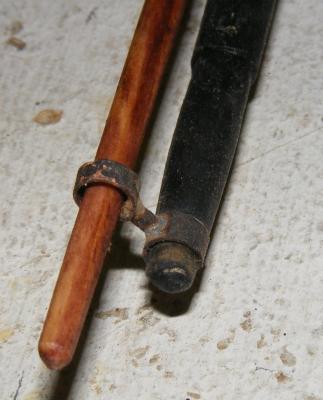
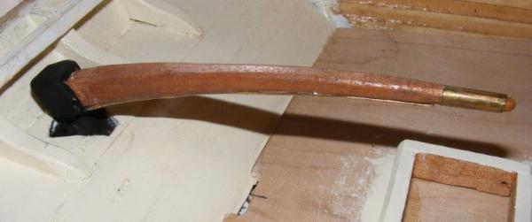
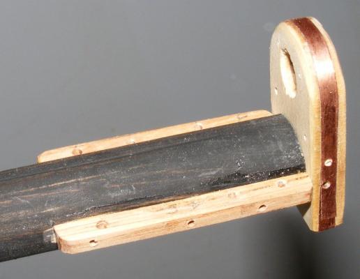
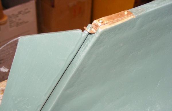
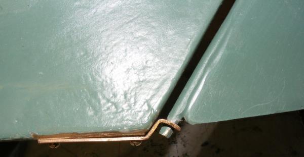
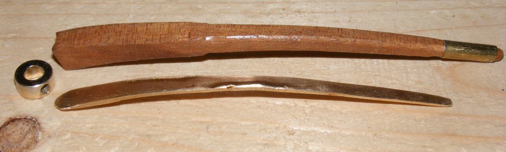
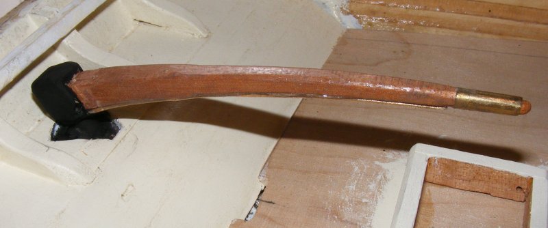
Not having a way to hide hard linkages between servo and rudder, I've opted to steer the boat using lines from the servo to the tiller and rig them so they look like relieving tackles. This isn't unheard of but it will require the tiller to be something more than a varnished bit of wood. Actually, I started with a varnished bit of wood...
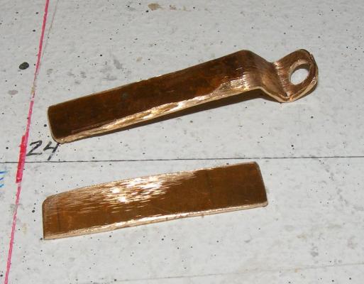
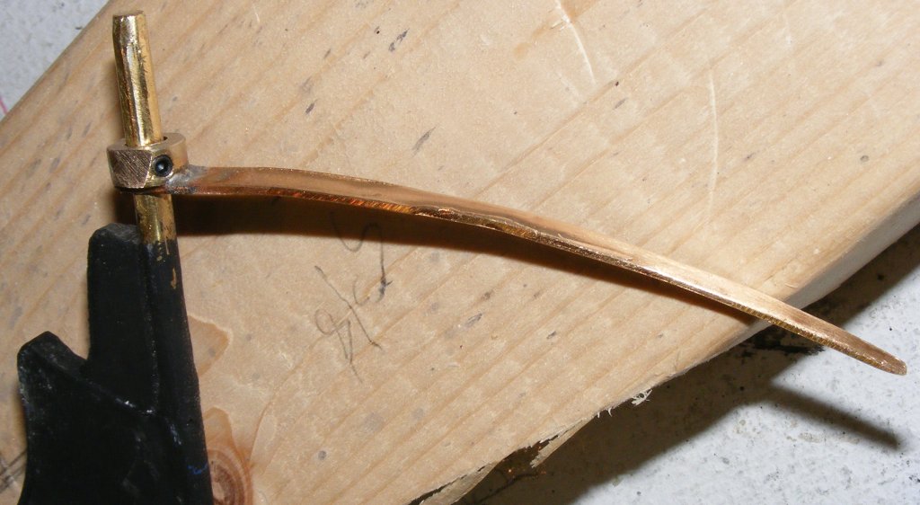
The real tiller though would be of metal, with the wooden part hiding that fact. A steel collar was sweated to a copper tiller and the rudder post hole drilled out. The collar was attached so the set-screw was angled off in a way it could be reached with an allen wrench.


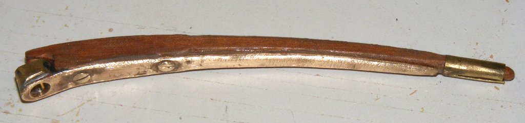
The wooden tiller was epoxied and screwed to the metal tiller.
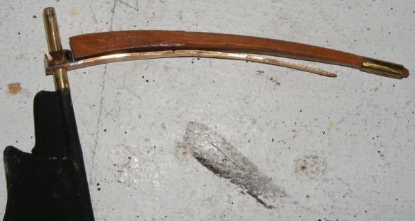

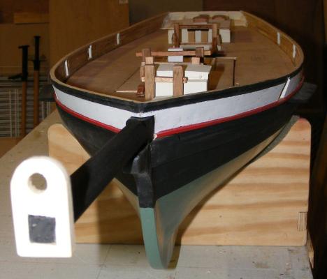
The rudder post rod was cut down so the tiller would be at the right height, and a false rudder head was built up to hide the collar.
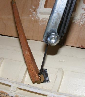
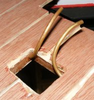
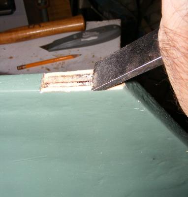
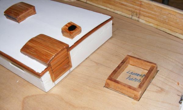
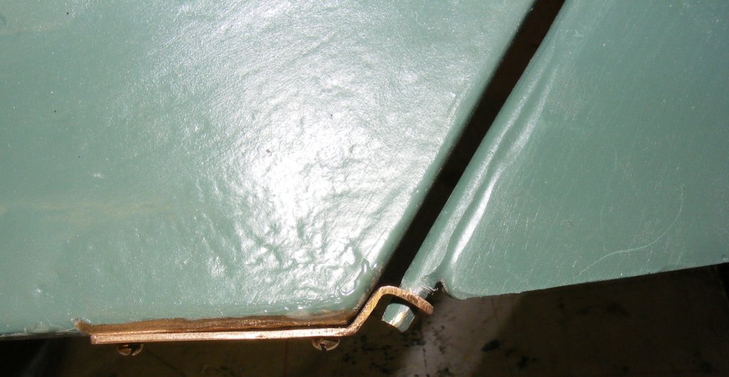
The steering cable will run, port & starboard, from the tiller to a block in the waterway, over to the lazerette hatch where it will go below and to the rudder servo under the cabin hatch.
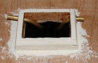
Two brass tube come through the lazerette hatch coaming to guide the steering cable below. A couple of wood blocks glued to the underside of the sub-deck anchor the tubes in place. The tubing was cut flush with the hatch coaming and is hardly visible.
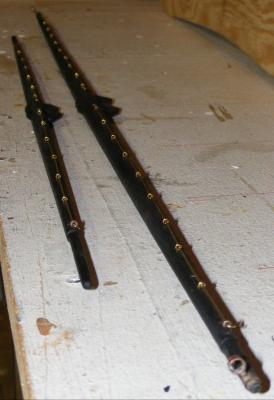
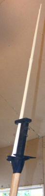
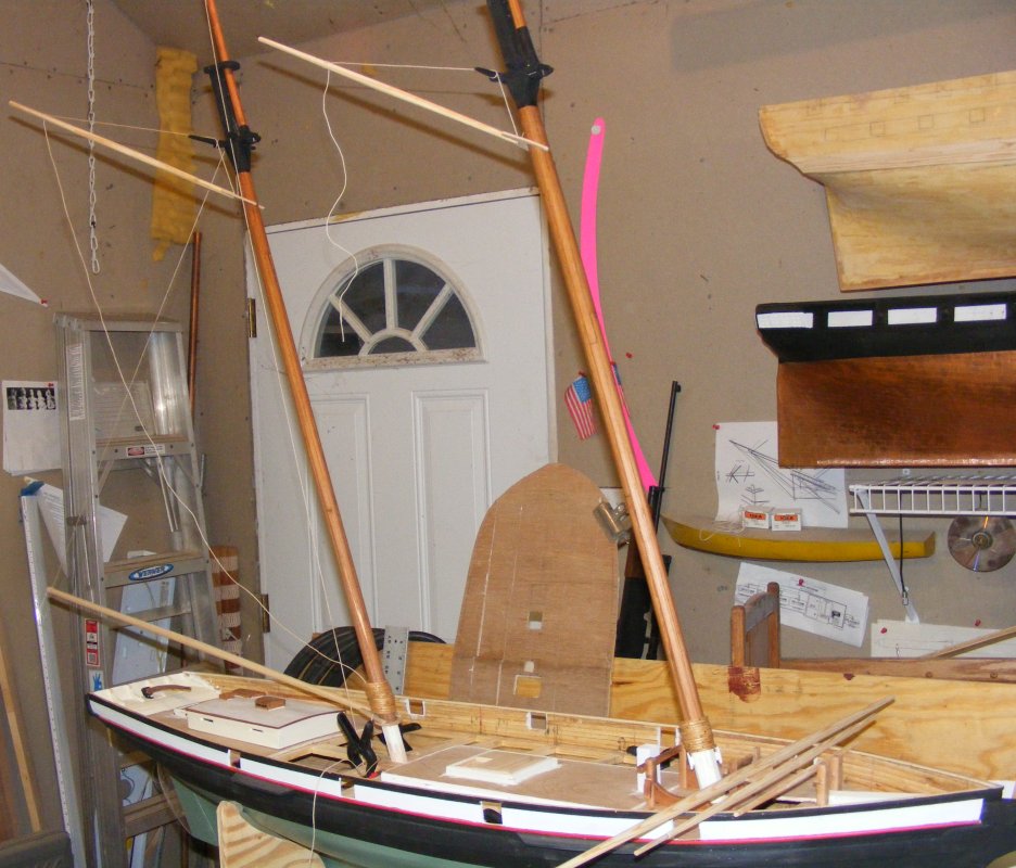
A pair of top masts was made from white pine. I look at a lot of photos, especially in Greg Pease's book, Sailing With Pride, to get their shape and finish correct for 1981 as they changed, and were even replaced, through the boat's life. The fid holes are lined with brass tube epoxied in place.
-
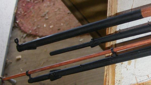
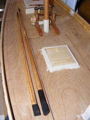
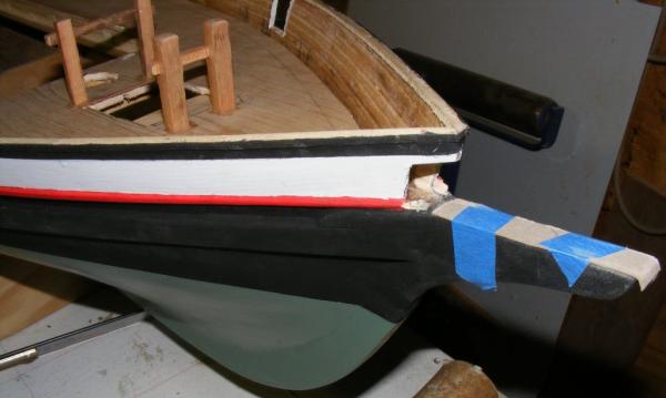
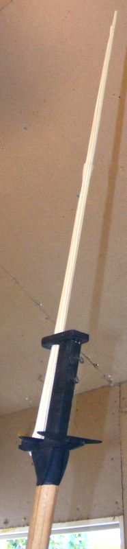
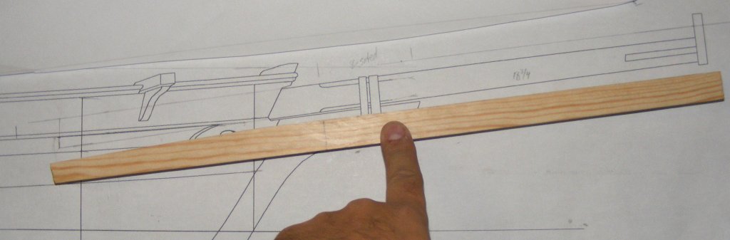
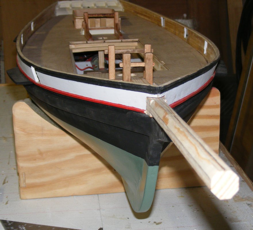
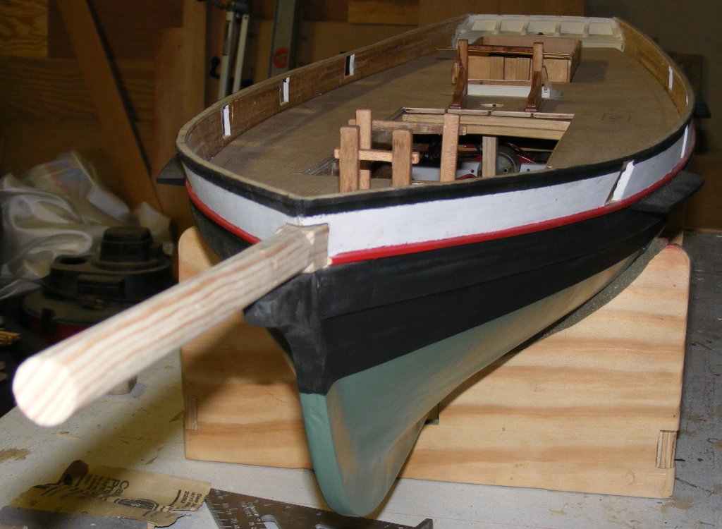
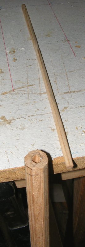
Next up, I started on the bowsprit. It was made from white pine. I wanted the masts as strong and light as I could make them, the bowsprit I wasn't quite as concerned about in that way.

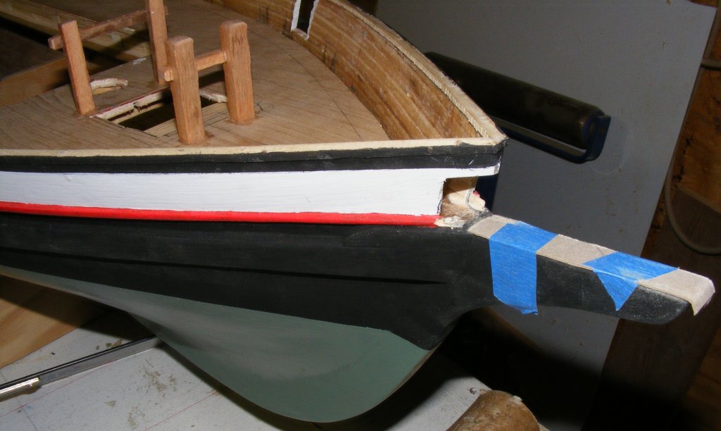
The bulwark had to be opened where the bowsprit came through. the bowsprit is square where it passes through the bulwark and it's top tapers as it goes aft almost down to half it's height. The bowsprit doesn't actually sit on the stem-knee, so I taped some card to pad it out and use it to guide the saw at the correct angle.
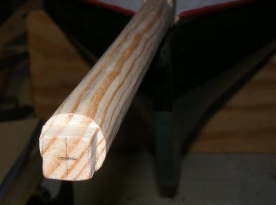
Forward of the bulwark, it's 8-sided, Just forward of the stem knee, it goes from 8-sided to round.


The cap was made from the same plywood as the mast caps, strapped with copper tape as was used to do Constellation's bottom. It's glued and pinned with brass rod onto the bowsprit.
The bees are red oak, glued and pinned with brass nails, the nails are CAed just before seated. Spreaders and dolphin striker are also oak. The striker is glued and pinned. Brass rod was used for the two U bolts, but they're just for show and aren't structural. The heel block for the jib boom is morticed slightly into the bowsprit.

The jib-boom is made from the same white pine. Started off square, was tapered, 8-sided, roughly 16-sided, then shave generally round, and finally sanded, stained and painted
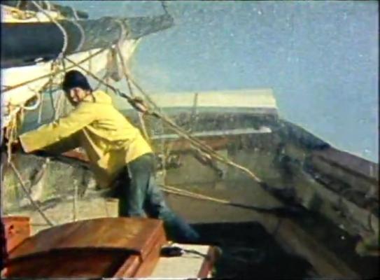
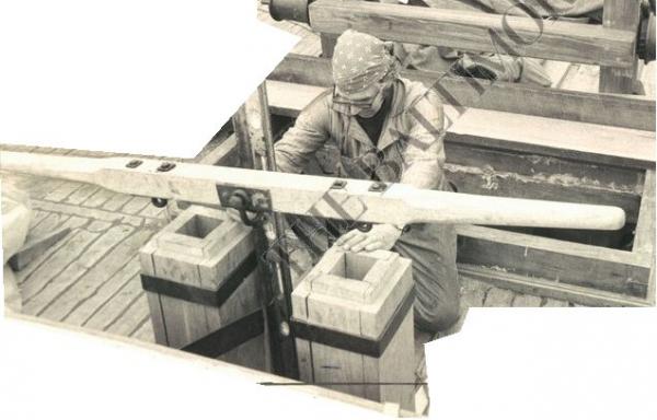
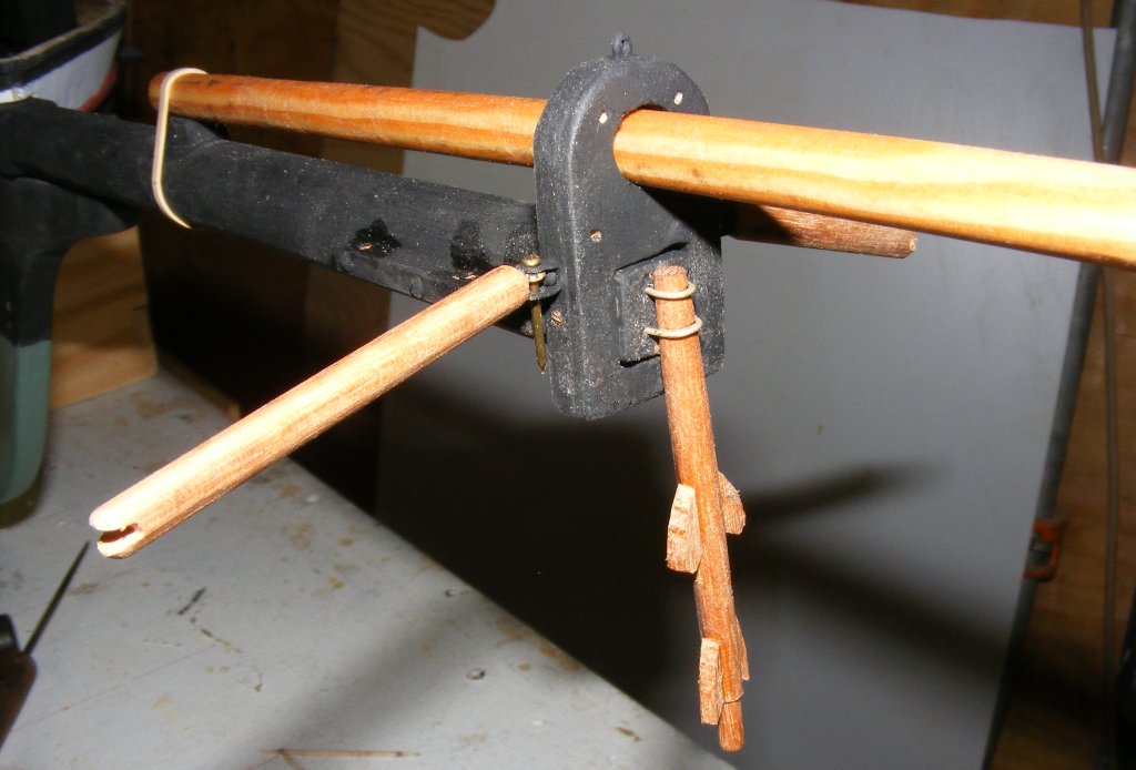
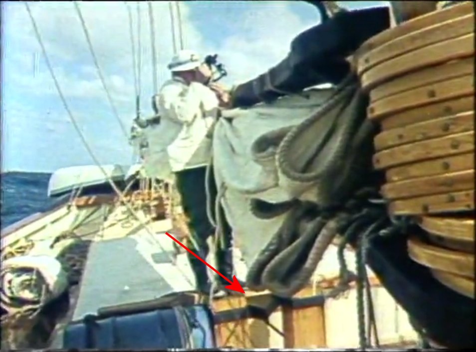
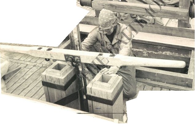
While working on the bowsprit, I actually got around to making the pumps. When I was on board, you could barely see these things, surround by water barrels, and we never used them, so I had no memory of how they were constructed, especially the ironwork the connected the handle to them. I actually found a video of the boat on her maiden voyage that had a glimpse of them I could use, and this is the result.
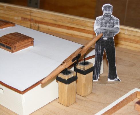

The fellow with the sextant is Melbourne Smith who Baltimore City hired to build Pride. I personally have nothing good to say about the man, so I won't say anything.
Turns out this is wrong. The iron V portion between the wooden pump heads is attached to the cabin trunk and not to the pump heads at all. The post the handle pivots on sits on deck. I found this out from a Baltimore Sun Papers photo of Fred, the yard foreman, working on the pumps during her construction. So, with a removable cabin trunk on the model, figuring this out should be interesting, but it looks like the pumps will be attached, all of them, the the cabin trunk and will come off with it when it's removed.
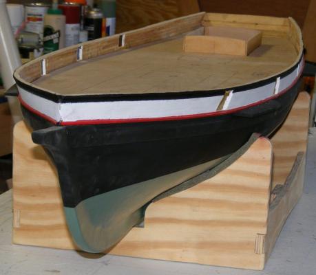
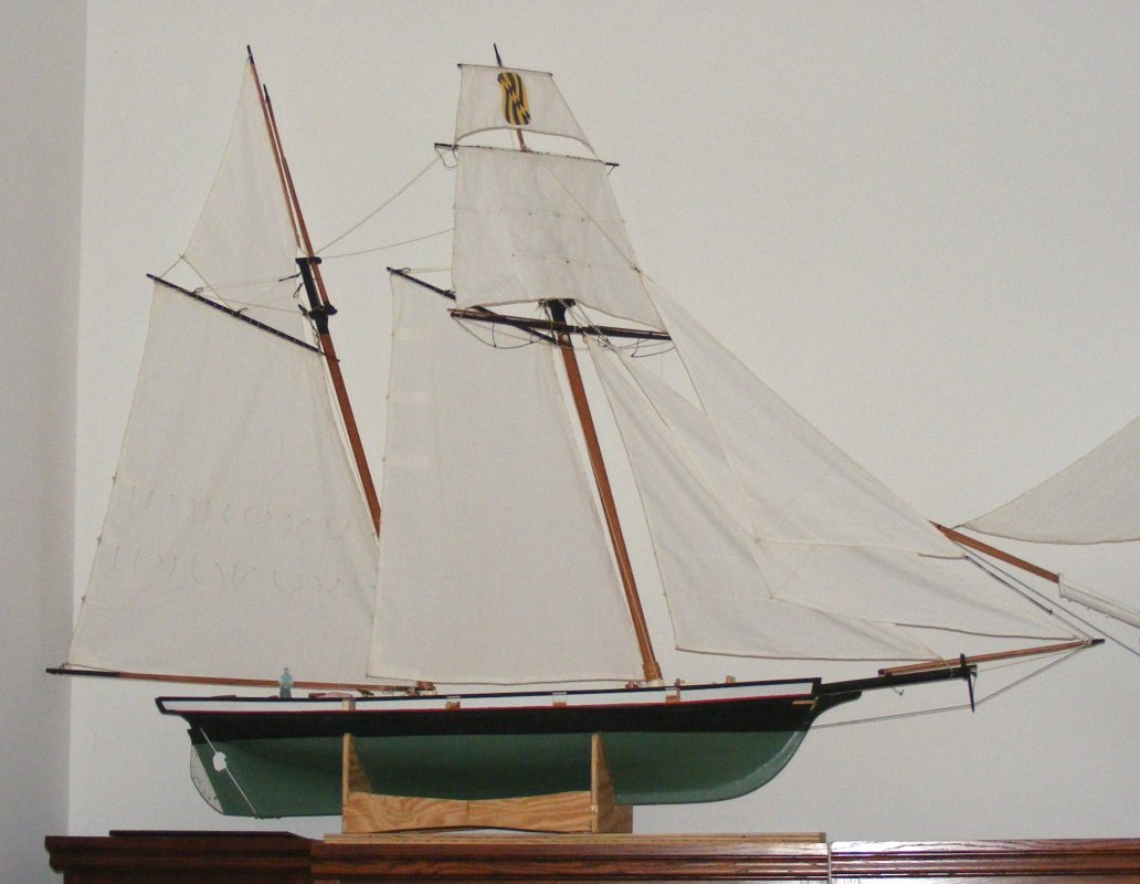
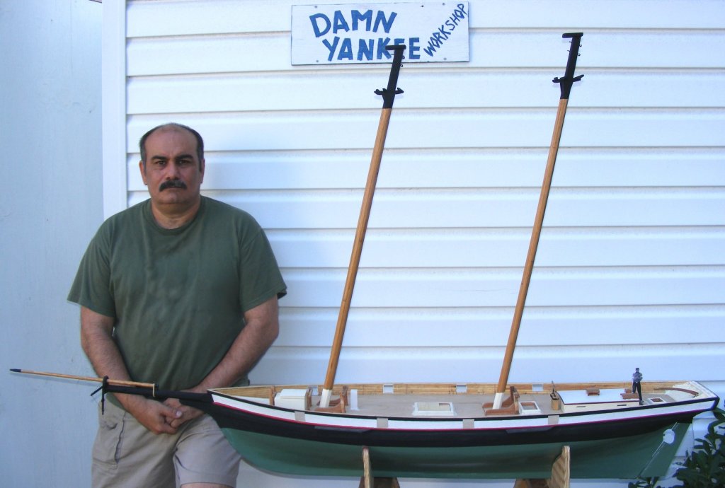
So, by the third week of May, 2012, the model was very definitely looking like her namesake, even if I no longer looked like I did then.

- Duanelaker, mtaylor, IgorSky and 3 others
-
6
-
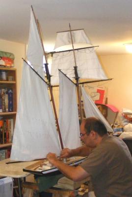
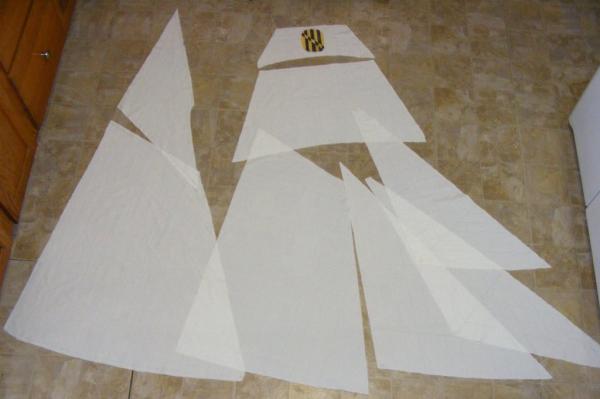
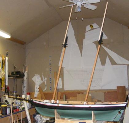
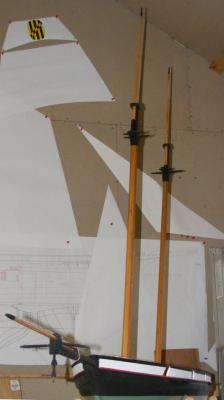
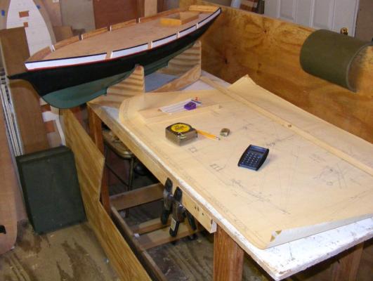
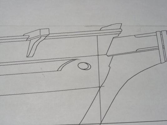
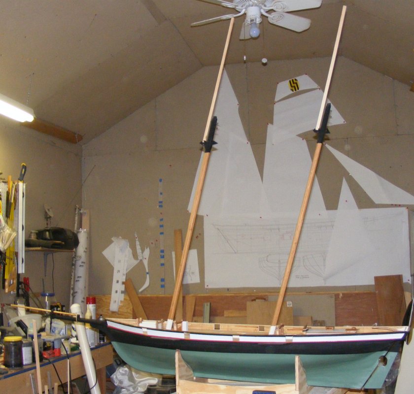
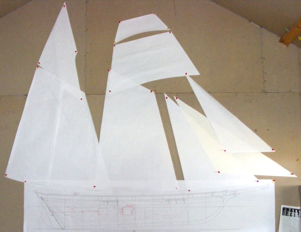
I cut paper patterns for the sails and pinned them up on the shop wall above the profile to see how things would look. It looked pretty darned good to me, Let's make some masts!
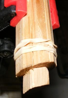
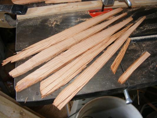
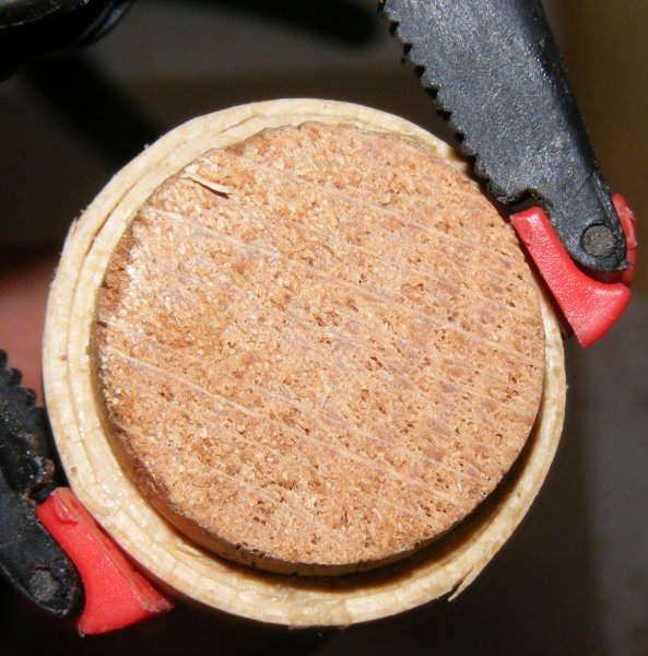
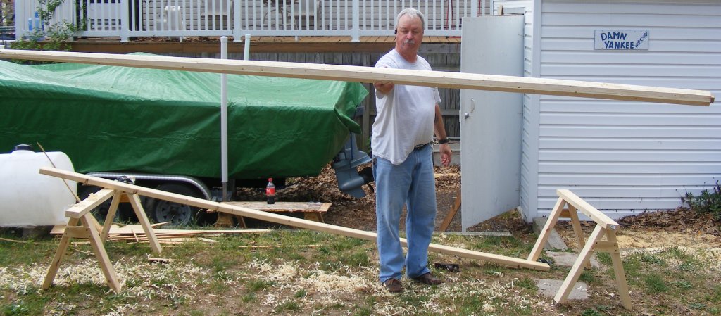
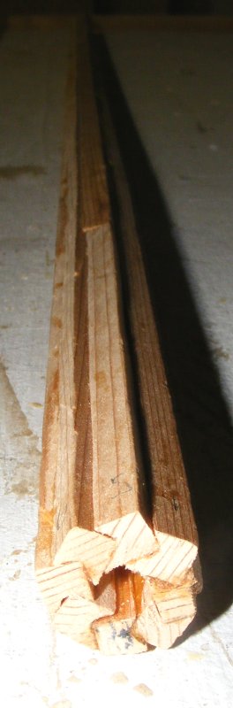
I made the masts using the "Bird's Mouth" method. There's a lot of math and geometry available on DuckWorks if you're interested in trying this system. My friend Mark, who was building a 12' skiff at my place, made the skiff's 12' mast using this method. Made from 12 foot 2x4's, it turned out a mast that was extremely light, and incredibly strong.
In short, Using the formulas for the size mast you want, you cut strips of whatever wood; in my case white cedar scraps left over from making Constellation's masts and spars. The bird's mouth is cut into the correct face. I used a V groove bit in a router set up in a table with finger boards everywhere to hold the work down, and against the fence. It took a little experimentation and playing around, but I eventually got the grove at the right depth.
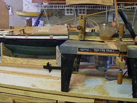 screen shot from the noisy video of cutting grooves in strips.
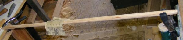
These strips do not need to be the length of the mast as you can butt them to get the right length. Just remember to stagger the butts, and not put any beside each other. The strips are then glued together. It's best to lay them out in some order of assembly as you do this. I used Tightbond III liberally, to glue things up. Take strips from your layout starting at one end of the mast and work toward the other end. Use rubber bands to hold things together as you go. You have to work fast because once it's all together you need to make sure it's straight, and you may need to adjust it, which you can't do once the glue sets.
Once the mast is made up, check it for alignment, fix it, and let it set up.

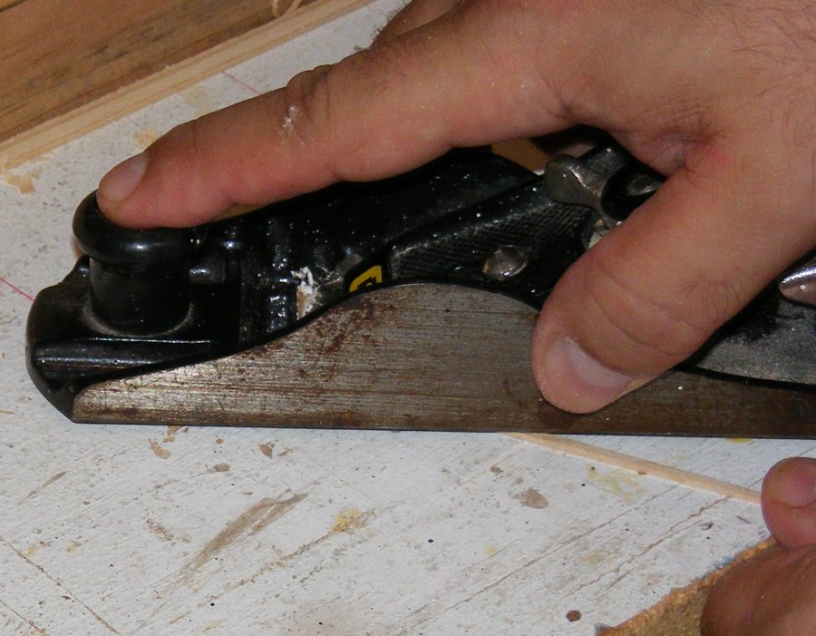
The spar is made 8 sided by planing off the corners. I then made an 8 sided dowel of pine to slide inside the mast at either end. The bottom one extends about 2" above where the boom jaws will sit, and extends out of the bottom for the step tenon. The top one about 2" below where the gaff jaws will land and extends out of the top about 1/2" for the cap tenon. These pieces primarily stiffen the spar from the step to above the deck, and at the doublings. The mast is shaved to 16 sides, then a rough 32, and sanded, a lot, to get it round where it's supposed to be.
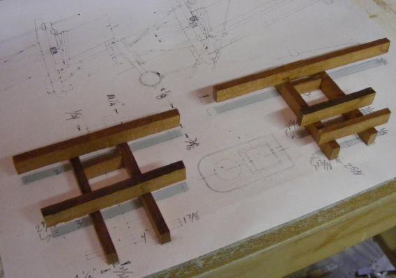
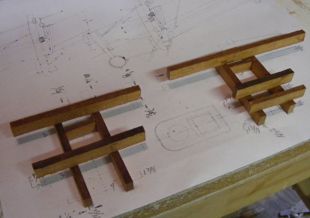
I made cross-trees and trestle-trees from the wood I used for the bitts and every joint is pinned with brass rod CAed in place. The mast head at the doublings was squared and hounds glued and pinned with brass rod. The mast caps were cut from 3/8" plywood. I figure there's going to be a lot of stress on this area when she's sailing, so made it as strong and light as I could.
Pride's mast head furniture was all painted flat black, so, so is the model's. The rest of the mast was stained and then given a coat of matte clear. The bottom of the masts were painted a cream color, which I hadn't gotten yet.

- fnkershner, mtaylor, yvesvidal and 3 others
-
6
-
On any model, it's often best to pre-rig yards and sails, and bend sails to yards, before the yards go on the mast. The less you have to fiddle with with the yards attached, the less your chance of breaking something and forcefully relocating the model to another part of the shop.
On that note: A friend has a dart board in his shop and keeps the darts at the bench. When something gets frustrating, he flings a dart at the board, instead of something valuable. If you try this, do not put the board near the entry to the shop area, they don't allow modeling tools in jail cells.
-
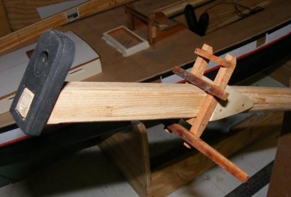
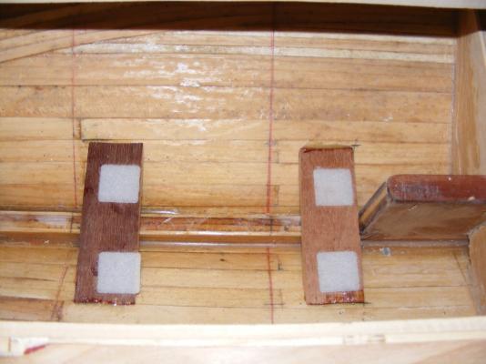
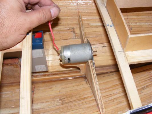
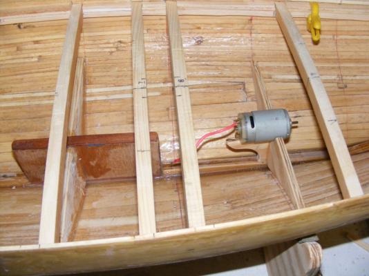
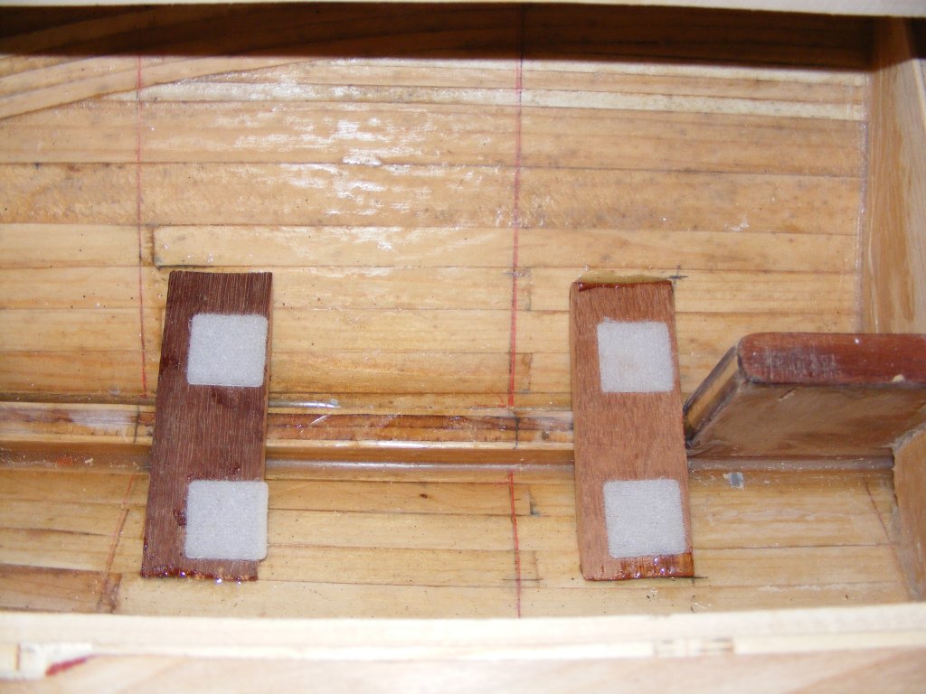
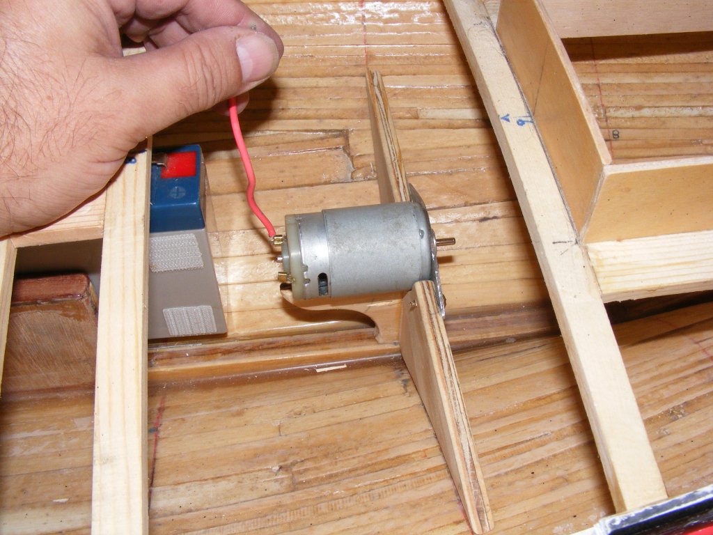
A set of beams was installed forward of the fin trunk, to hold the battery. It will lie flat, as low as possible, and be held by Velcro tabs.
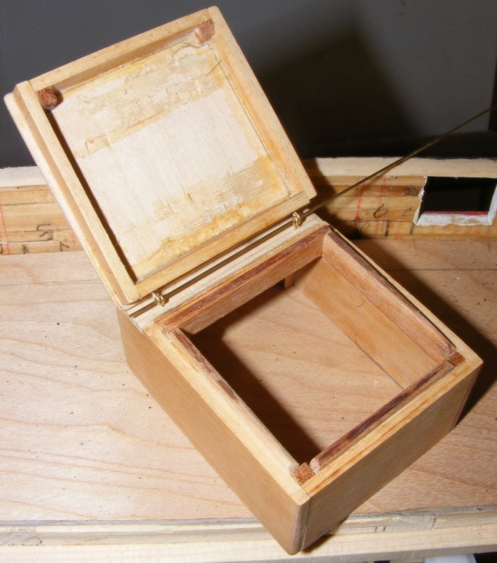
The focs'le hatch on the real boat was different than the plans, it was much taller with a hinged lid. I used the same wood used in the other hatch coamings and built it up in three layers, log cabin style. I had some notion of putting something up here, like an on/off switch, but I doubt that'll happen. None-the-less, I made a hinged lid and a hole in the subdeck.

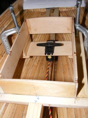
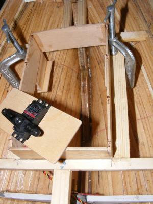
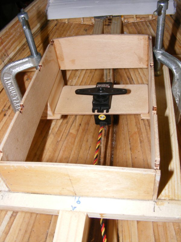
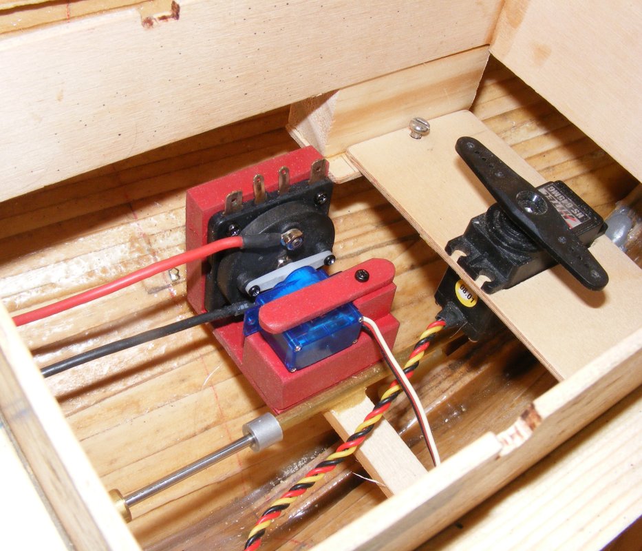
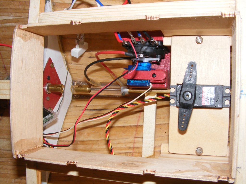
In side the cabin hatch, I put in brackets to carry an aircraft plywood shelf for the rudder servo to mount in. It's held by screws and will be removable for servicing.
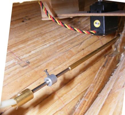
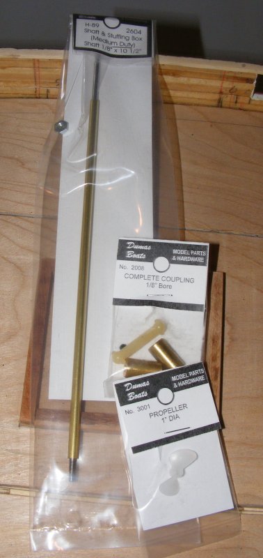
The parts for the prop shaft and motor couplings came in

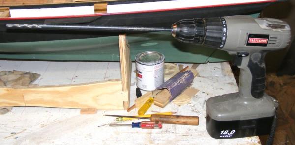
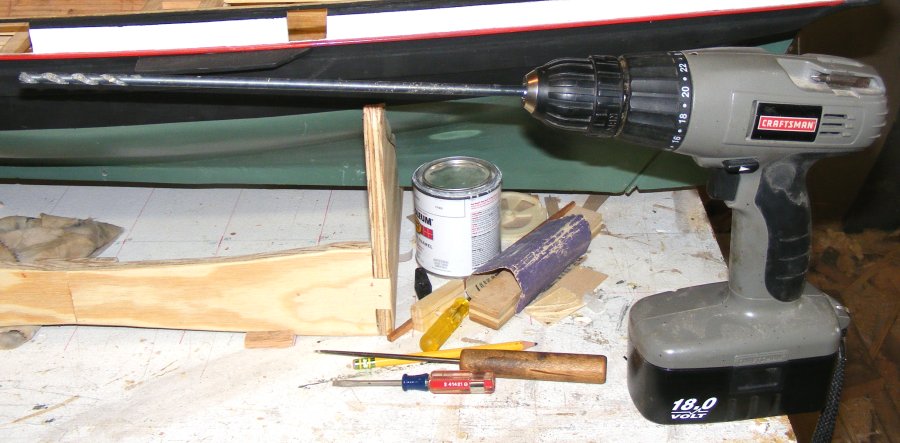
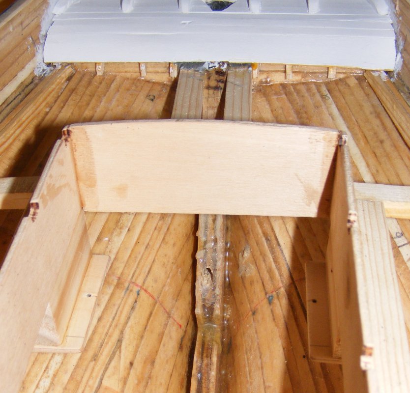
Which meant drilling a hole in the stern post for it. This was done with a long 3/16" bit, over sized so the brass tube "stuffing box" can be adjusted and surrounded by epoxy. This is yet another thing that ought to have been done to the keel while it could lie flat, before it was placed on the forms. JB Weld was added inside to ooze into any nooks and crannies the epoxy missed.

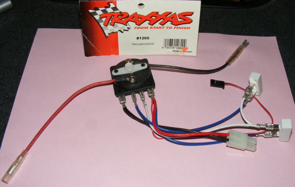
Another ordered part arrived - a rheostat type speed controller, with forward and reverse. This is operated by a micro servo, so I made up a mount to handle it.

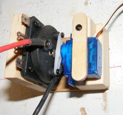
It was fitted inside the cabin hatch on a beam that also serves as a stuffing box support, painted with that red spray paint, and fixed in place.


- gieb8688, fnkershner, mtaylor and 5 others
-
8
-
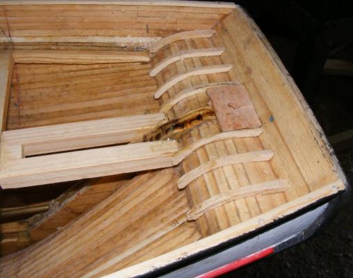
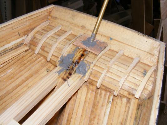
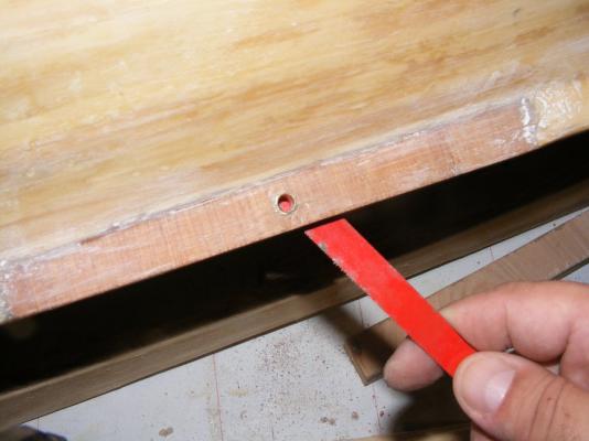
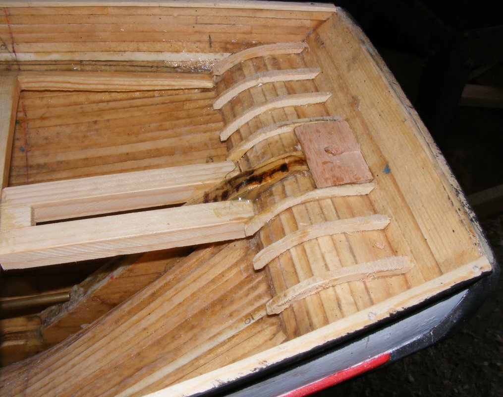
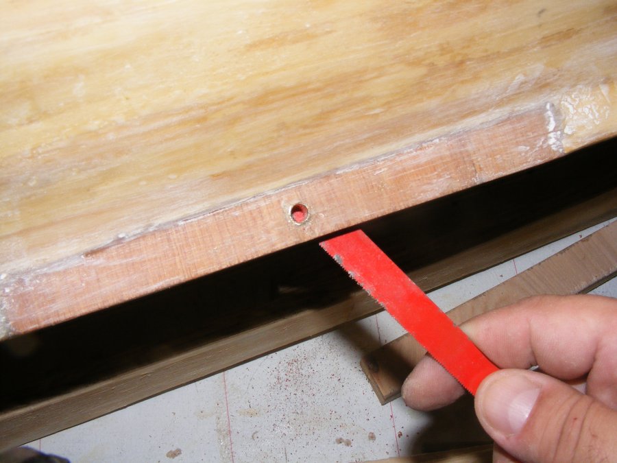
The counter frames went in, showing why I had to trim down the stern post a while back. An oak block was glued in where the rudder tube would go in, to strengthen this area, and a slightly over sized hole drilled through it and the counter.
A brass tube was epoxied in with JB Weld. A brass rrod taped to the sternpost behind a spacer made sure everything set up in proper alignment.

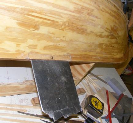
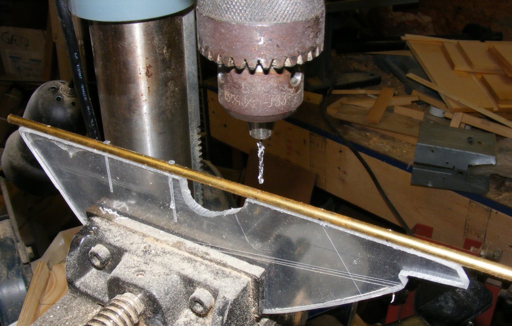
The rudder was cut from polycarbonate (Plexiglas) and given a brass rod rudder post that was glued and drifted to it with smaller brass rods.

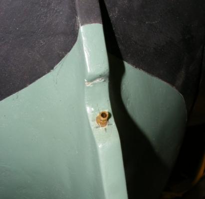
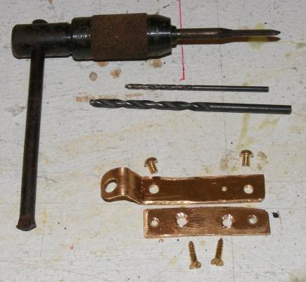
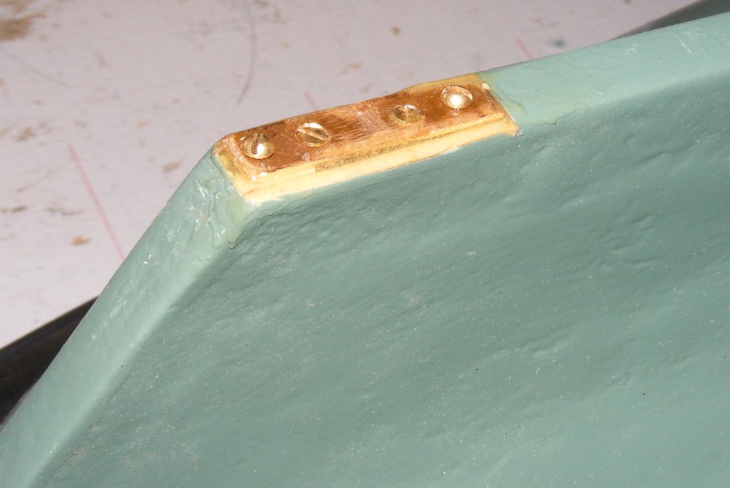
A copper plate was cut to size with 4 holes; two for mounting, and two that are tapped for mounting the gudgeon plate. This plate was inset into the boats heel, epoxied and screwed in place. This way water can't seep into the plywood keel because every hole in the hull is lined with epoxy.
The gudgeon plate is attached with brass machine screws and is removable.

The rudder post slide up through the rudder tube at the counter. The tiller collar will hold it from falling out, the tube keeps it from sliding further up. The gudgeon plate holds the heel of the rudder to the hull and serves as the lower hinge point against the forces the rudder will encounter. Removing the rudder entails removing the gudgeon plate and the tiller, then the rudder drops right out.
The visible area around the rudder hole was painted black and the counter planked up with bass sheet. All the wood framing here was painted in epoxy, and each plank was painted with epoxy onit's under side to make sure moisture inside here wouldn't get into the wood. Later this was primed and transom knees were installed.


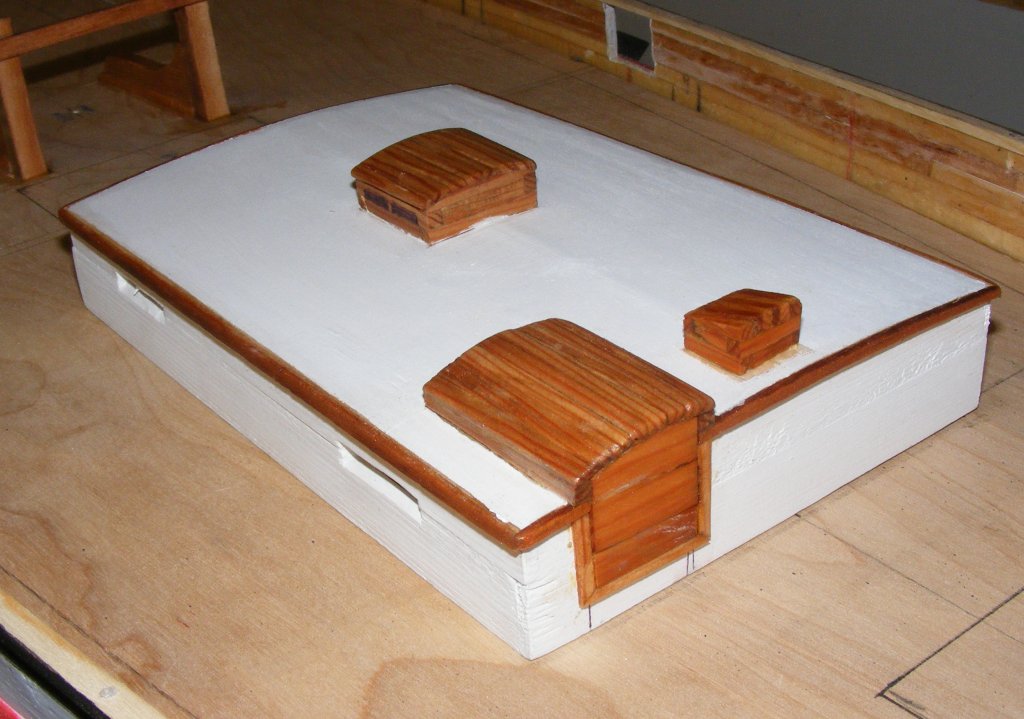
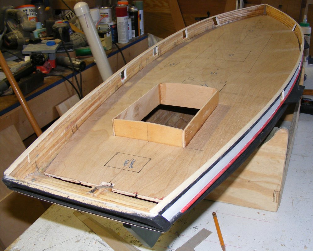
Using bass sheet again, I built the cabin trunk, the visible part that is in essence, a lid. It's details, molding, skylight, compass box, hatch, etc; were all made from the wood of the Pride's top mast I was given earlier. Looking at one of my pictures where the cabin can be seen, I think this wood worked out fairly well for this application. It wasn't strong enough for anything else, like the tiller.
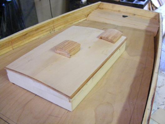
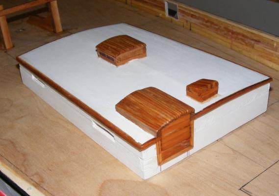

I used that "might-be-mahogany" wood used on the bits to make the hatch coamings.
I also used it to make the tiller. You may have noticed there is no space to speak of inside the counter where I could hide control linkages for the steering. Instead I'll actually be using the tiller to steer the model, so it will have to have some strength.
-
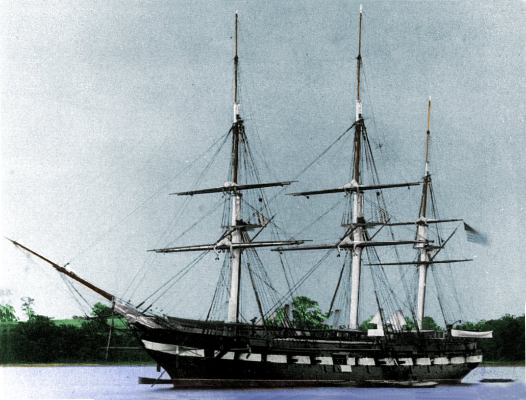
I'm a bit late chiming in here, but I have a great deal of data on the sloop of war Constellation, and if someone is of a mind to turn this kit into something of value, I would be happy to share my data with them. I can't speak to the idiosyncrasies of this kit, as mine is a scratch build, but if you're going this route, it's only a kit up to the gunports and it's scratch from there up.
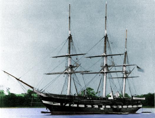 Constellation 1871
 -
-
-
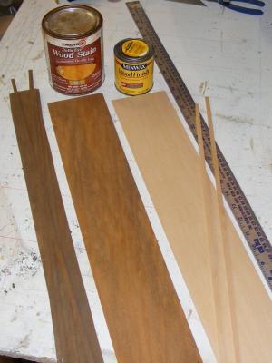
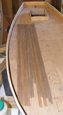
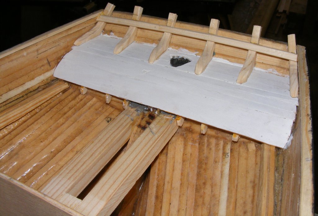
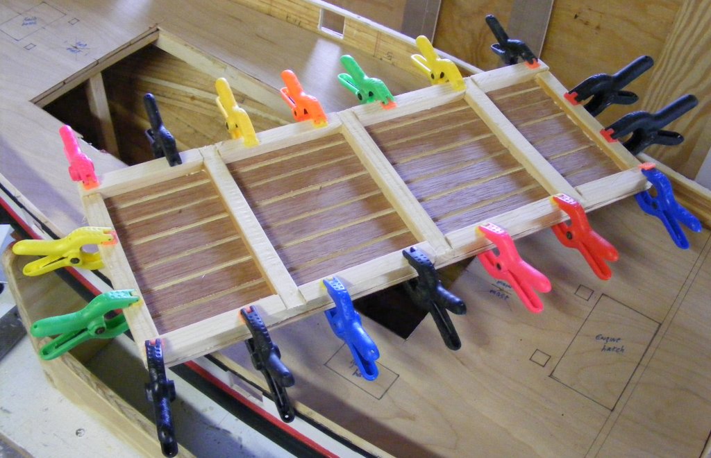
The subdeck's underside will get painted with epoxy which will seal it as well as glue it to the deck beams. A layer of 1/32" bass strips about 1/4" wide will serve as the deck planking. It will be died a combination of stains to approximate the color of Prides original decking. These will be set in slow-cure epoxy when the time comes.
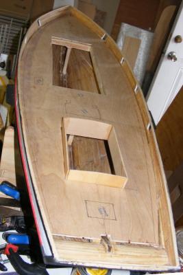
All that's a ways off yet, as there's still things to be done in the hull before the deck can go on...
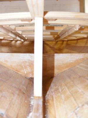
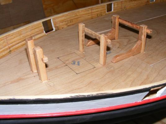
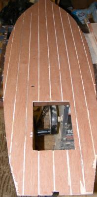
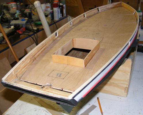
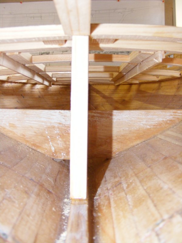
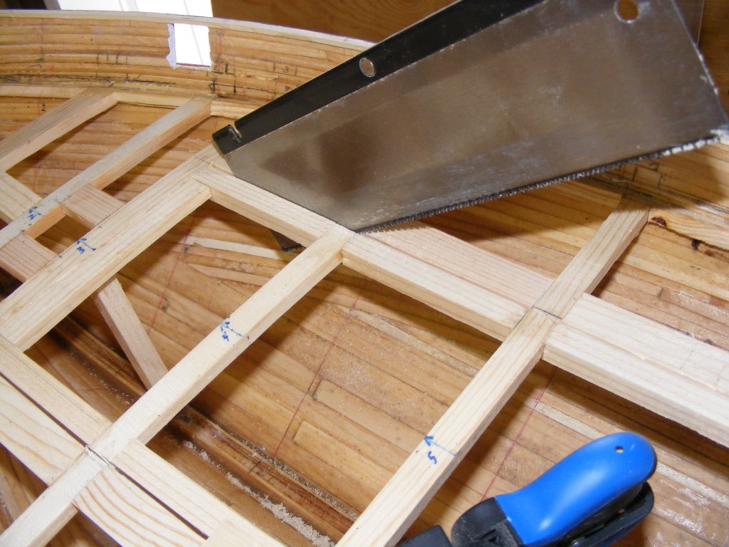
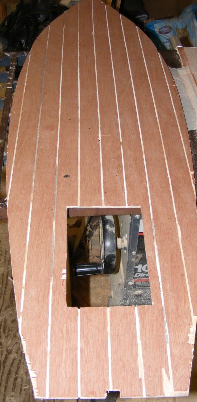
For instance, the access hatch has to be framed and cut out. A pair of posts were put in near the mast partners between the deck beams and the keel - these are compression posts and should help prevent deformation of the deck, just in case.


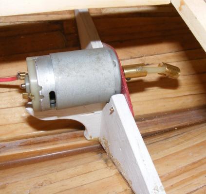
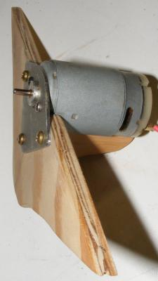
The motor mount frame was painted and the mounting plate was painted with the red spray paint from earlier. It was then epoxied into the hull.
I was volunteering at the Naval Academy Museum model shop and once night one of the other fellas brought in a handful of splinters. Seems the Pride had her fore-top-mast replaced at Richardson's Yard in Maryland and these pieces came from the old spar. That means they were on the boat when I was. Now to figure out how to incorporate them into the model.
The bitts were made from some dunnage found on a dock that looks like it may be some sort of mahogany. It's hard and it matches the color of the originals pretty well.
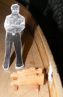
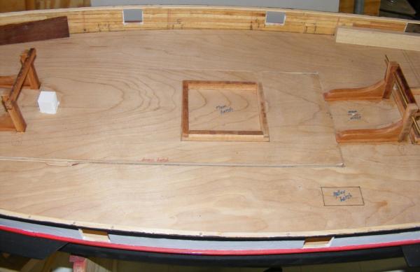
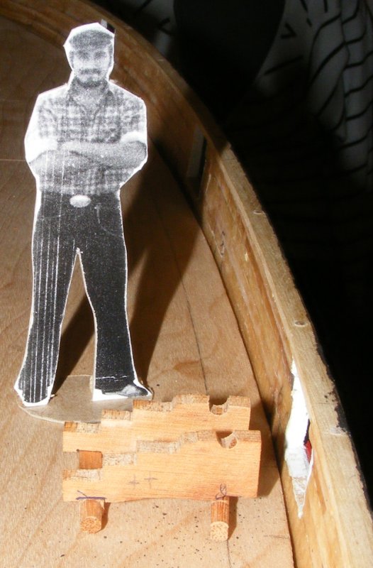
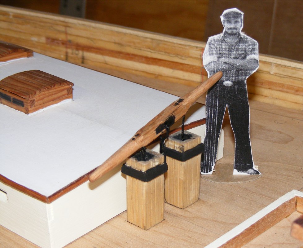
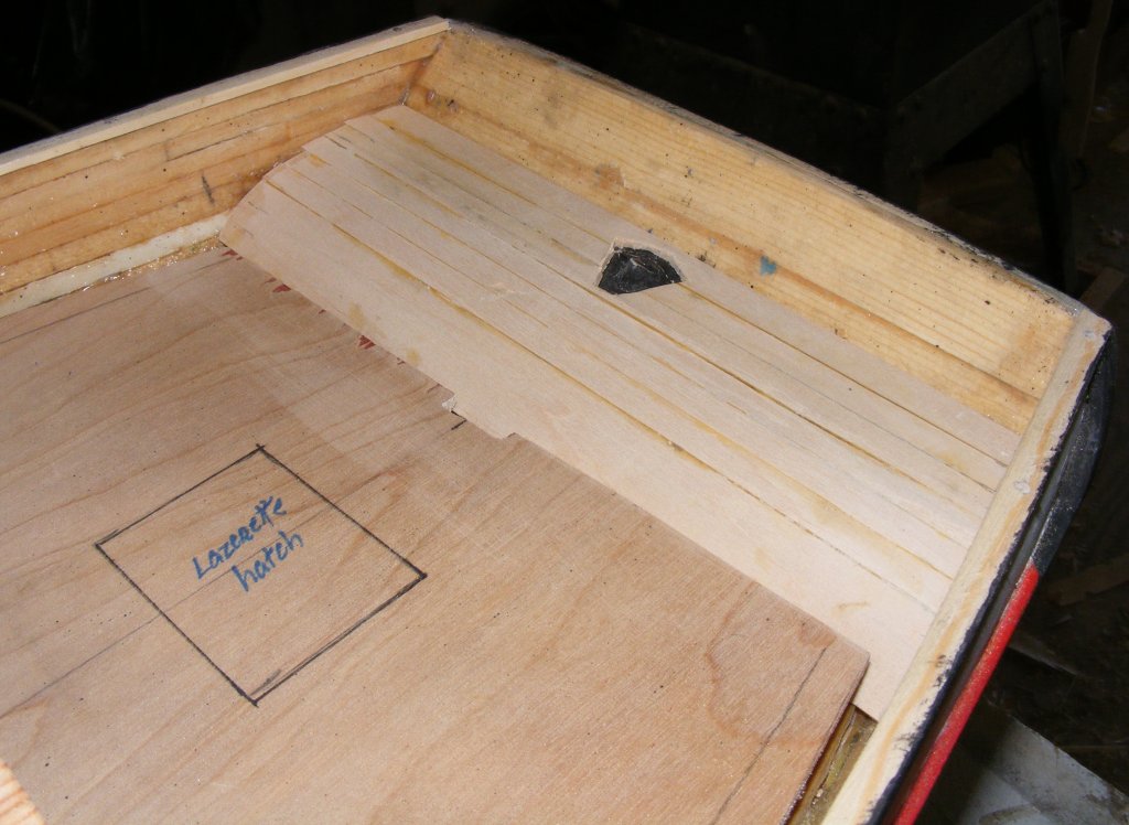
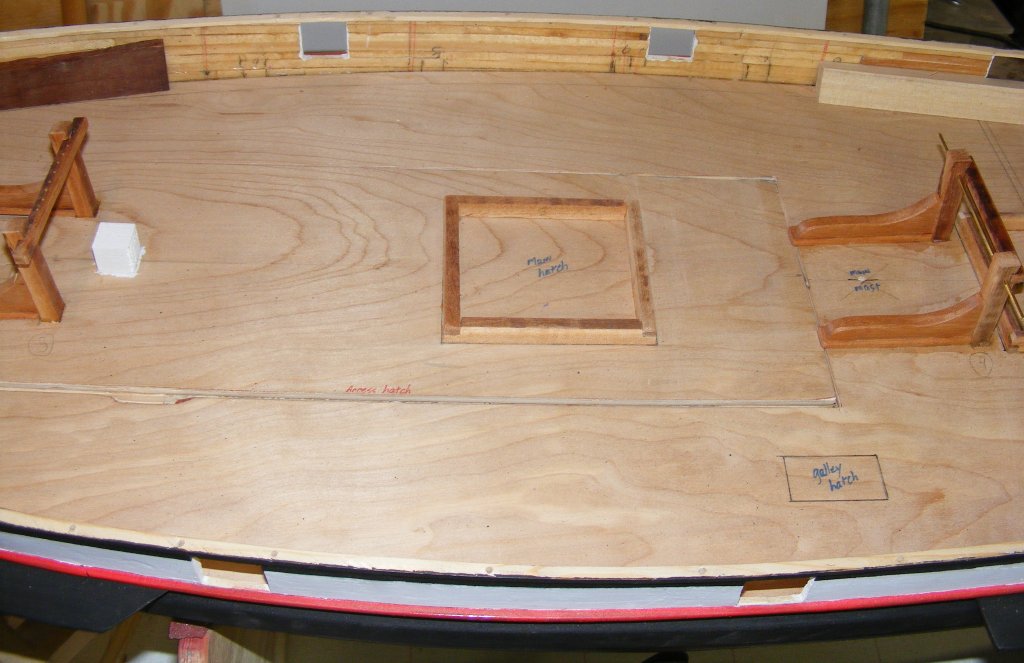
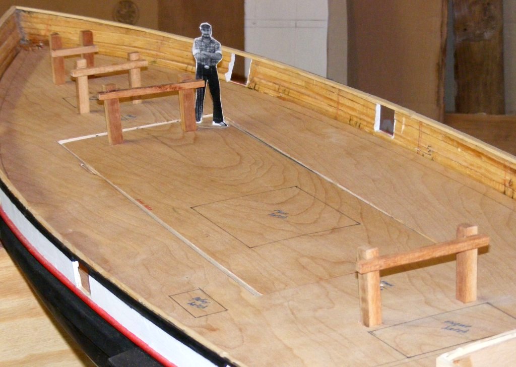
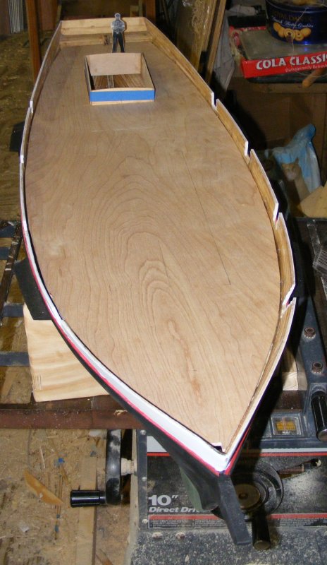
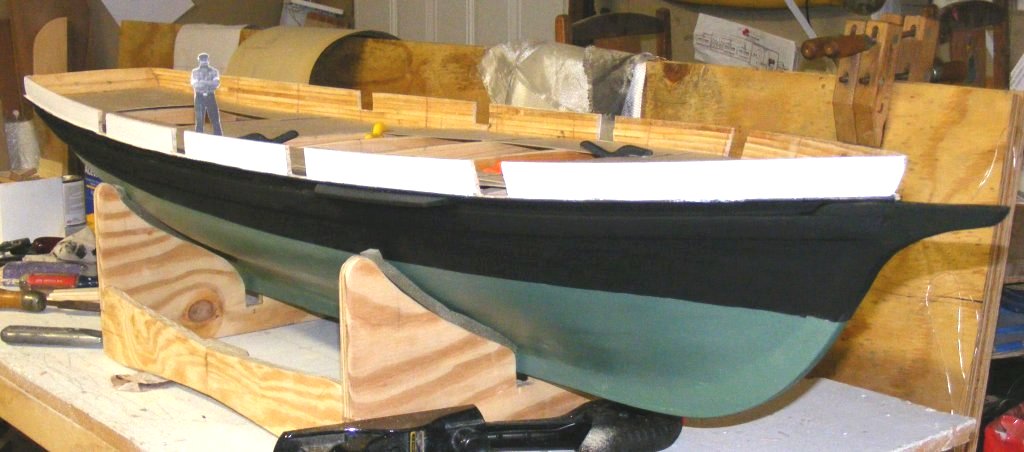
Note the subdeck is marked with locations of deck objects, such as hatches. On the access hatch is the scale main hatchway - which obviouslt wouldn't have been large enough for the model. On the right of the photo is the engine room hatch. The small rectangle on the left of the deck in a box that the galley stack pokes out of. The fellow standing there is me, in 1:20 scale. It's a picture of me from about a year before my time on Pride and serves to show scale in the photos.
The hatchway marked in the right photo is the focs'le hatch.

-
From the smell of them, I thought the old model's rigging was tarred just like their prototypical counterparts - they always smell like Stockholm tar to me.
-
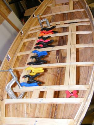
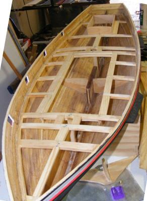
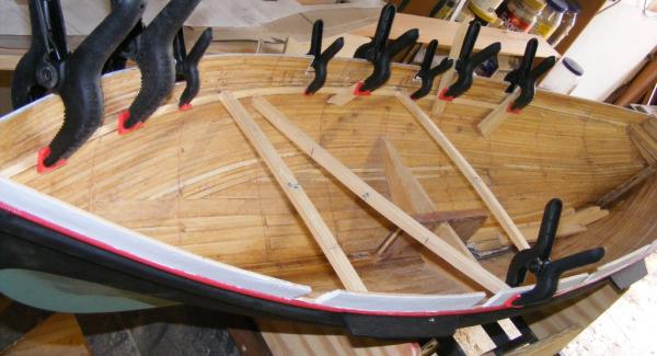
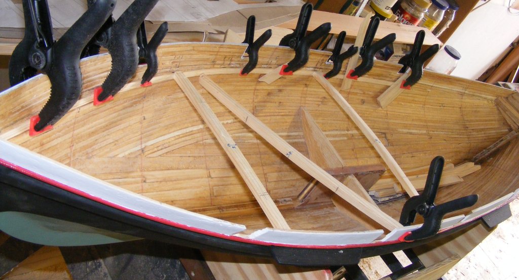
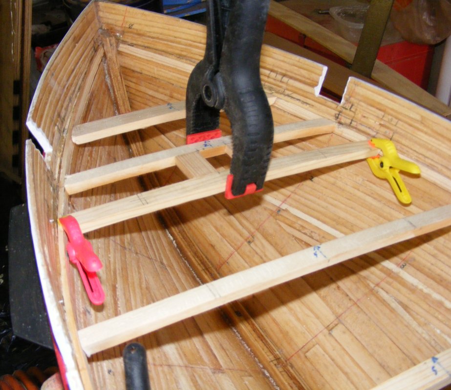
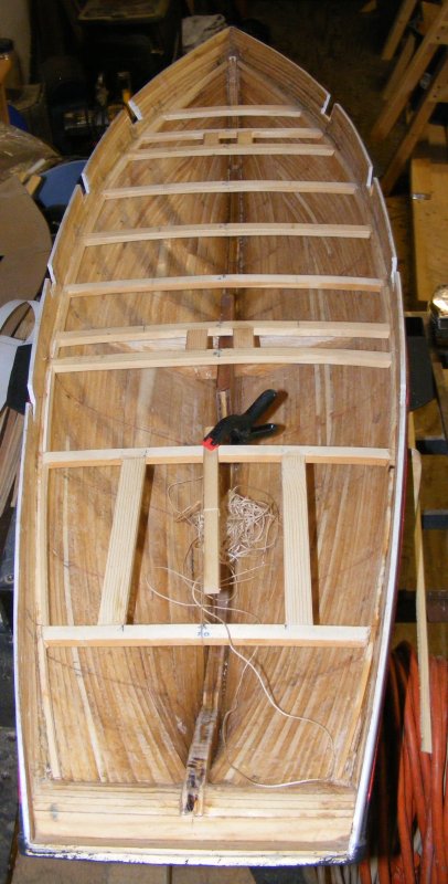
So, once more in go the clamps. This time, making sure I measure from the right point, I used a different approach. I laid in two layers of 1/8" thick strips, then installed the deck beams - now recut thinner - butted to the clamp. Another layer of 1/8" strip was installed between each beam. Mast partners were installed, then framing for the main cabin and the access hatch. The access hatch doesn't correspond to any hatch actually on the boat - none of them was large enough at this scale to give me the access inside I needed.


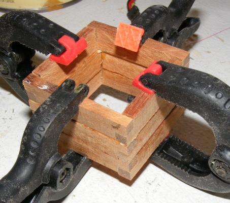
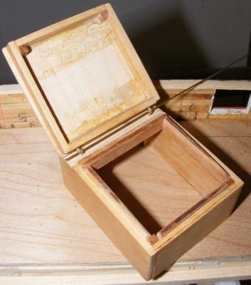
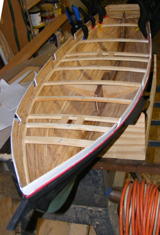
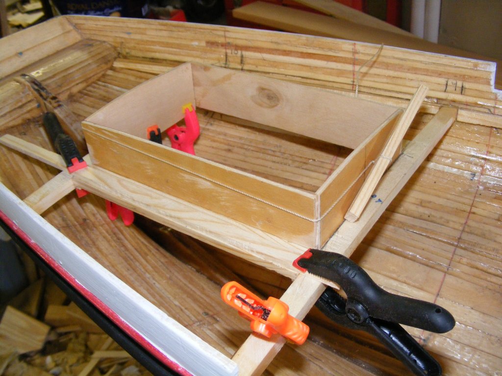
The inner cabin trunk is framed from 1/8" plywood that came from a cigar box, or something like that. This isn't the cabin you'll see, but an inner sleve the outer cabin trunk will slide over, like a box lid. This will help keep out water.

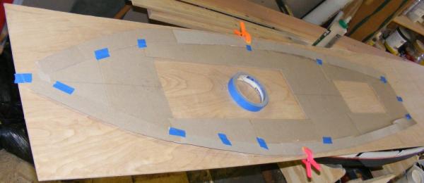
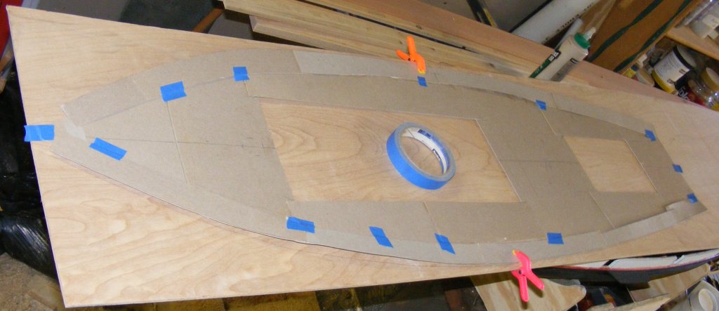
Card stock was used to lay out the deck and make a pattern. The sub deck was cut from 3/16" luan plywood. It was kerfed underneath to help it flex in two directions; sheer and camber.

After giving the top strake a coat of black, I started marking the spar plan with 1:20 scale dimensions in preparation of making the spars.
I made a mounting plate for the motor from an electrical box cover plate. The motor came from an old cordless drill.
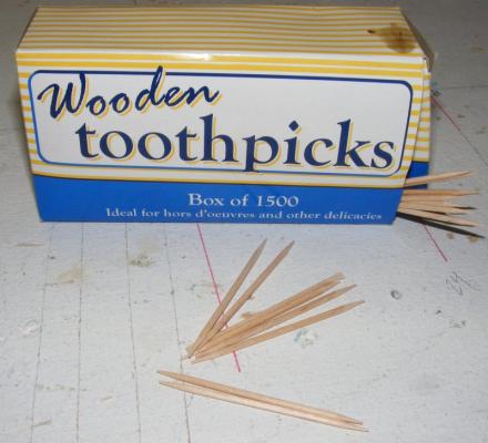
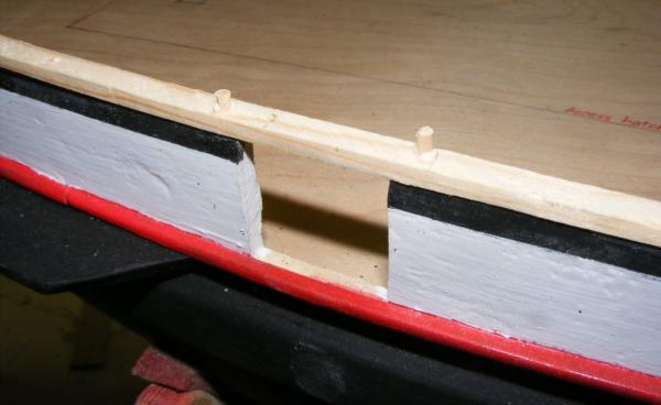
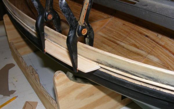
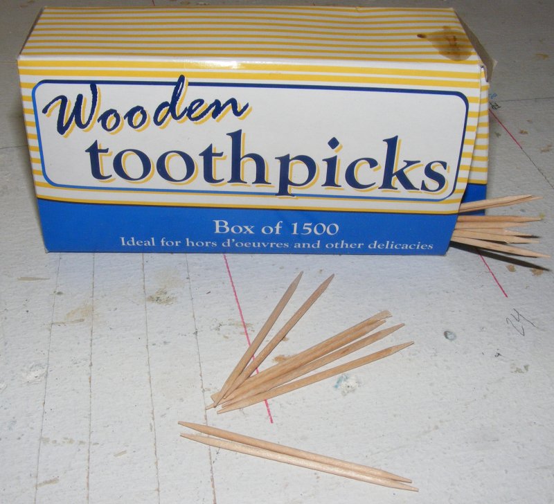
I was getting concerned that a section of bulwark might get broken off by some big clumsy oaf, like me, so I put a rail on to connect it all. This isn't the finish cap rail, but more of a structural member. This rail will actually be in two parts. This part is the inner part mounted flush with the outboard side of the hull. It's glued and trenailed (wooden toothpicks) into the top of the planking. An outer part will be applied later, bring the rail to it's correct width.
And some more paint.
- yvesvidal, fnkershner, Piet and 2 others
-
5
-
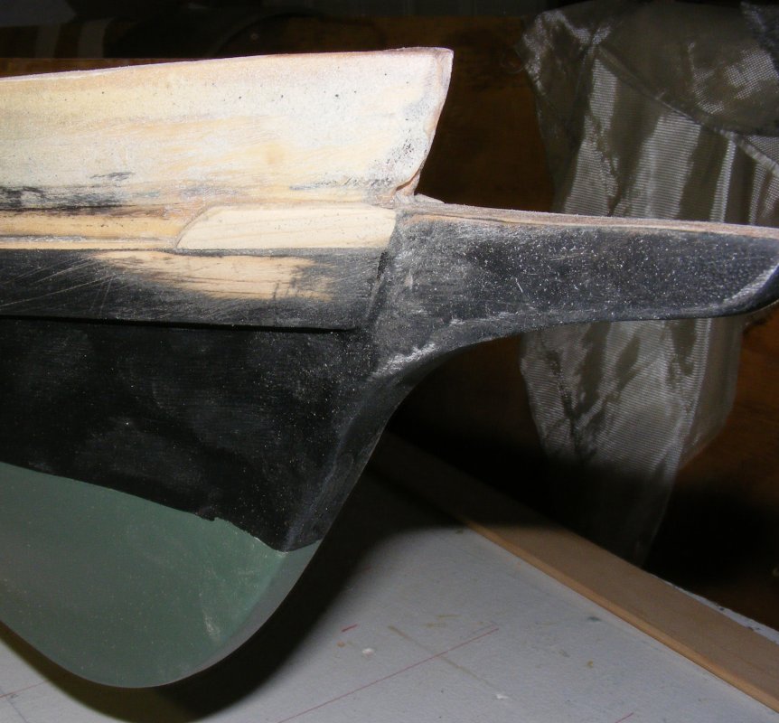
Fortunately when I got the plans from Gilmer, I got the full set with structural details, especially a cross section of the structure; because it's not at all easy to tell where the top of the deck is. This apparently was a problem found by some company doing flooding analysis on her, they were given a profile and not knowing where the deck was, calculated to the top of the rail.
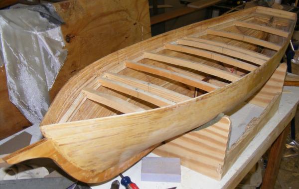
As it is, the top of the deck is level with the top of the wale, which was the next piece to be installed.
I had a length of screen molding we used as a batten, or spline, when laying out Mark's skiff on the plywood. It was precisely the width of the model's wales.

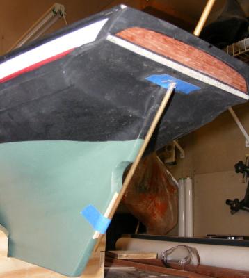
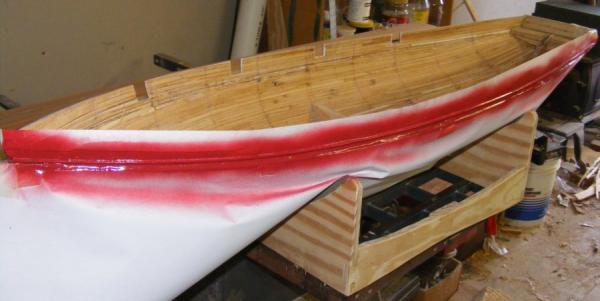
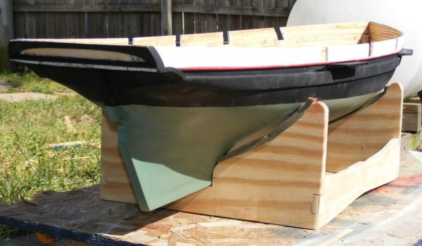
With the wales on, the prop notch cut, and the dagger board trunk installed, hull was ready to get some paint.
First, a coat of primer.
Then I found some spray paint that pretty closely matched the color of Pride's bottom paint
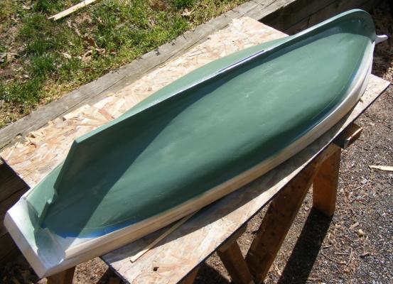
I thought I had a picture of Pride out of the water where the color of her bottom could be seen, but nearly all my shots of her hauled out are black & white newspaper photos. This image is from 1980 and you can see a little of her bottom color.

I hand painted some flat black above the waterline.
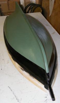
The wale widens forward at the hawse pipes, this was installed next, but I'm not drilling the hawse holes yet.
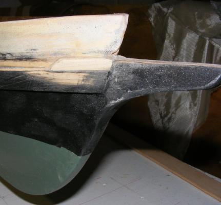
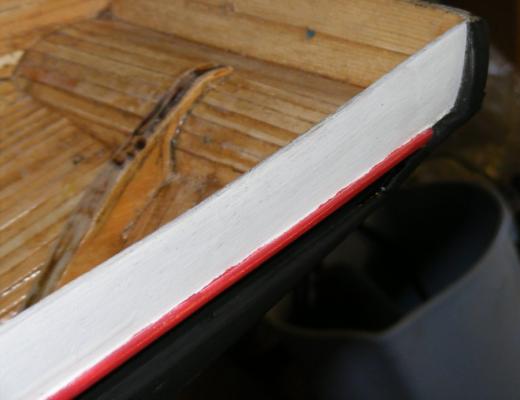
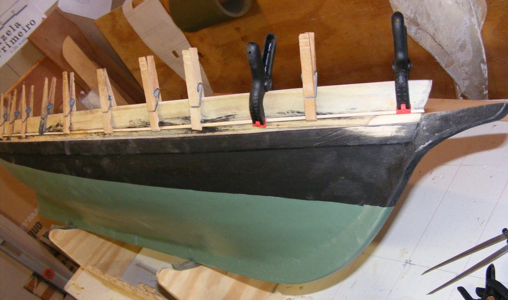
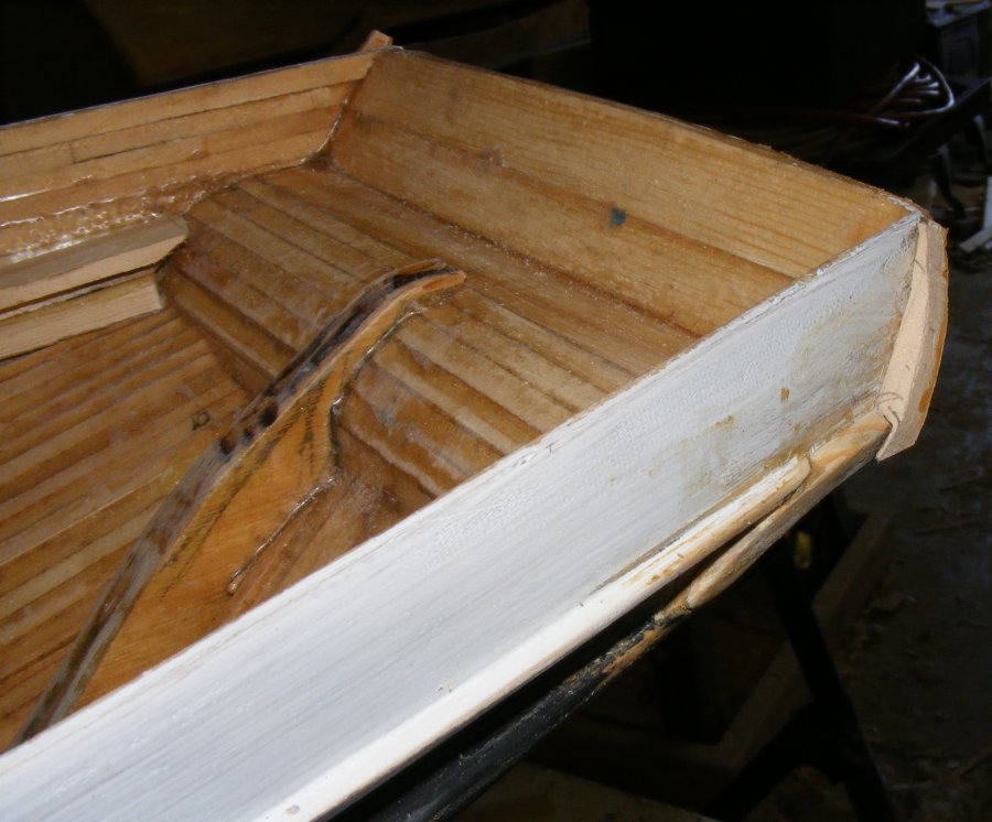
Again, referring to the cross-section, the top of the deck extends to the top of the wale. This is capped with a waterway log, which itself has a cap. There's light planking above this to the cap rail. The portion of the waterway cap that's exposed outboard forms something of a channel down the boat's side, and this part of the cap is painted red.
I cut some 1/16" square strips and sanded them 1/2 round. This was applied to the outside of the hull to represent the outboard portion of the waterway cap rail.
At the top of this channel between the wale and the waterway cap, snugged up under the cap are the channels. This were more white pine, thicker at the hull and tapered to about half their thickness outboard. One was installed. Looking back, I'm not sure why I only did one, but
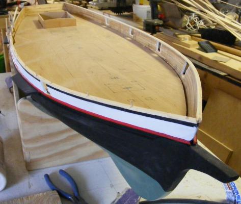
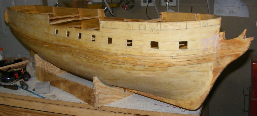
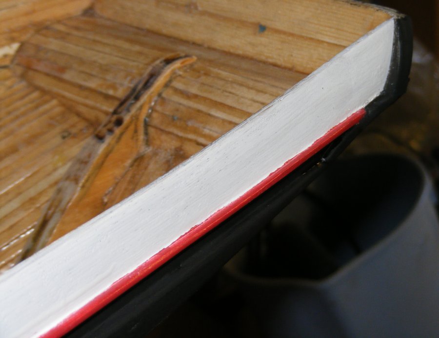
Some black paint touched up the faux waterway rail and the channel below it. Then put a coat of white on the bulwarks, and cut the gunports.
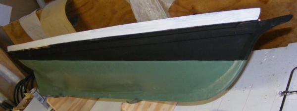

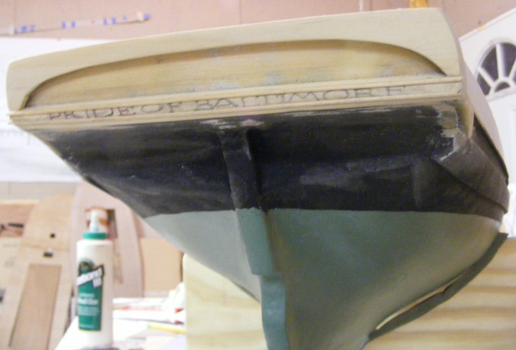
The wing transoms and fashion pieces were fabricated and installed, and the facny piece and moldings on the transom..


Something didn't look right with the deck clamp, and upon investigation, I found it was off at the bow and stern. It was too well attached to just detach and move, so I pulled it out completely. Had I installed the wale first, I could have more accurately gauged where to install the deck clamp (minus the thickness of the plywood sub-deck and decking).
Finding a small container of red paint turned out to be a challenge. I wound up with a $2 can of spray paint and proceeded to paint the waterway cap.
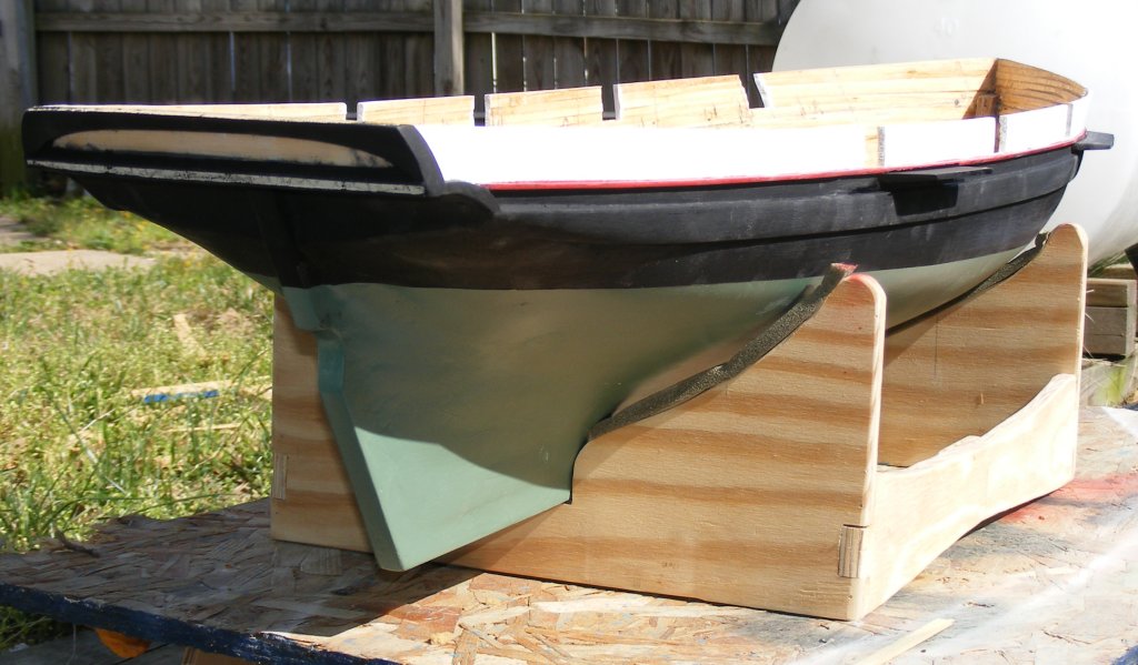
Finally, the rest of the channels were installed.
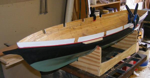
And everything painted
-
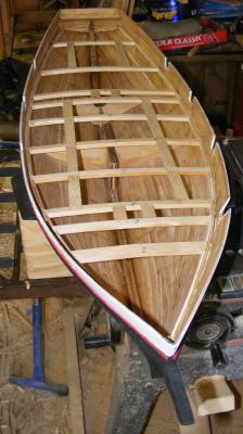
With the hull glassed, I began to install the deck clamps. These were of the same pine used to plank the hull, only 3/8" wide and 1/8" thick. One later was epoxied to the hull.
The placement of the deck beams was determined based oh hatch locations, mast partners, etc.
While my friend Mark was building his skiff outside the shop, I put some of his leftover epoxy into the bilge of Pride's hull to fill crevasses, seal, and strengthen the garboard area.


There are things that should be done to the keel while it's still just a flat piece of wood, and before it's a permanent part of the hull. Cutting the cut-out for the propeller is one such thing.

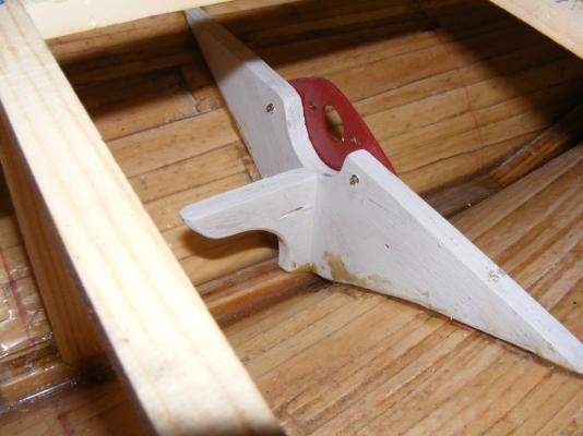
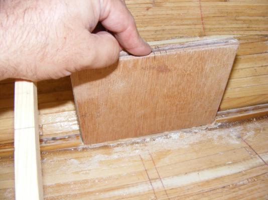
I wasn't sure how I was going to attach the external ballast until I saw some Newfie schooner models as big as Pride that used a simple fin with about 15-20 pounds of lead in a bulb. Going with the idea, I started building a dagger-board box for the fin to slip in to. The sides are 3/16 luan plywood, glassed on the inside faces, with a pine separator epoxied on fore and aft.
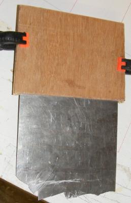
The remaining portion of the aluminum sheet I cut Constellation's yard trusses from will be the fin.
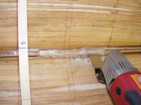
This oscillating tool I got from Harbor Freight for $10 made quick work of cutting the hole for the trunk to fit in to. This, of course, is another thing that should be done to the keel before it's part of the hull.
Portions of the form at that station became internal braces for the dagger-board trunk. They would be epoxied in.
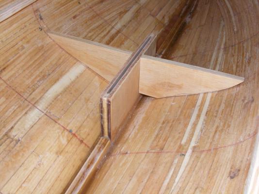
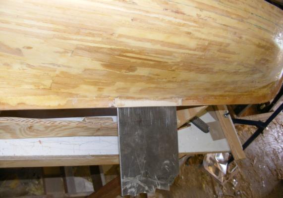
The trunk was itself epoxied in. After sanding, some glass cloth was laid over it to fair it into the hull and the keel. Anything not covered with cloth was painted with resin.
The trunk got a cap from a bit of cherry I had around and a motor mount was fashioned from one of the forms.
A hole was drilled at the center of the trunk along the keel and a brass tube was epoxied into it. When it set, I cut the tub flush inside and outside. A matching hole was drilled in the fin, where a brass machine screw and nut would hold the fin to the boat. The tube protects and seals the end grain of the trunks plywood where the screw will go through.
I began to fit the deck beams, but these seem thicker than they need to be. They're like this on Constellation, but there's a lot more head-room inside Constellation compared to Pride where space is at a premium.
- qwerty2008, mtaylor, yvesvidal and 1 other
-
4
-
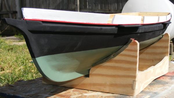
I do need to build a pram to chase them around in.


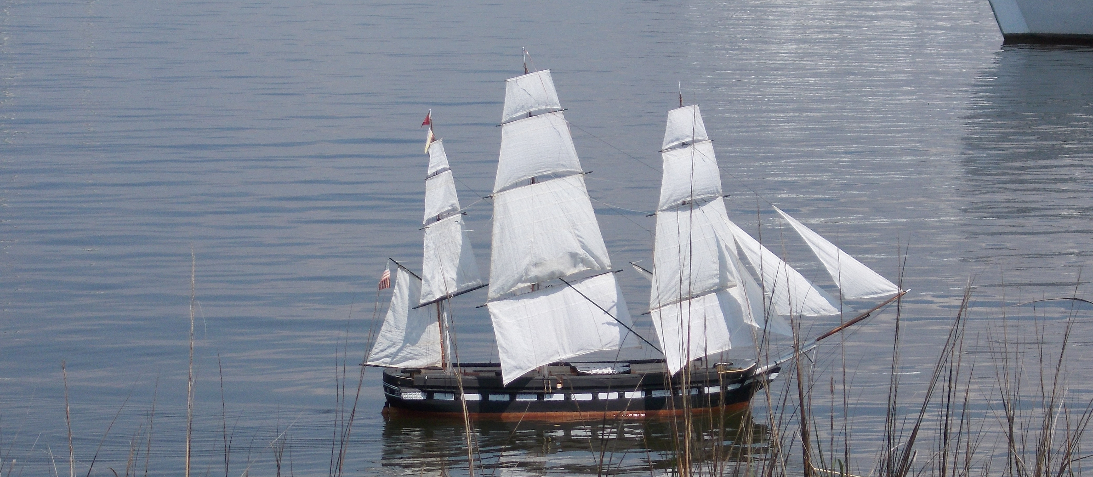
Gazela Primeiro c.1979 by JerryTodd - 1:36 scale - RADIO - Barkentine
in - Build logs for subjects built 1901 - Present Day
Posted · Edited by JerryTodd
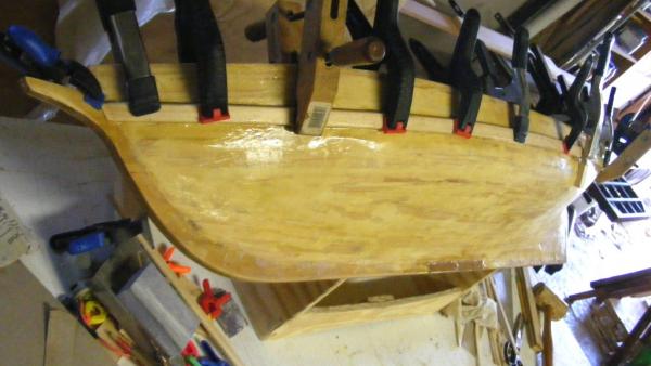
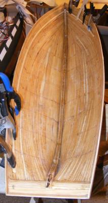
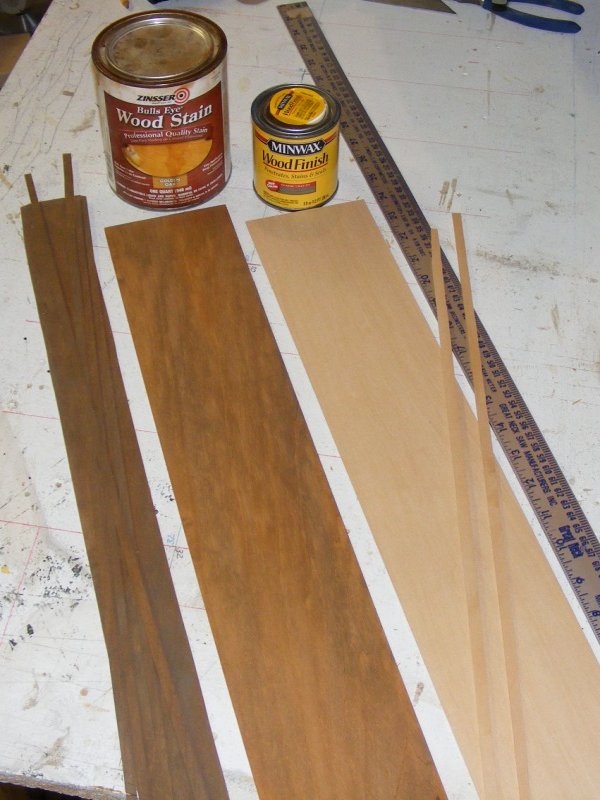
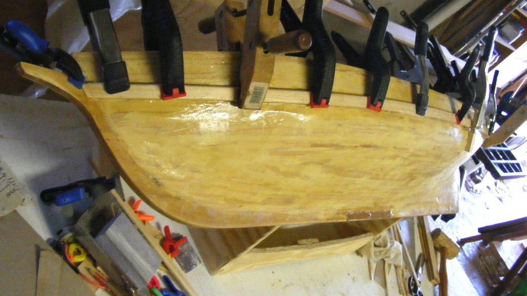
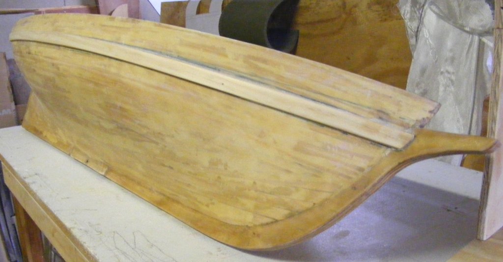
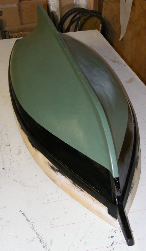
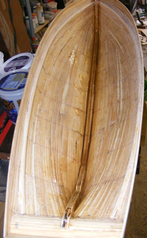
Once I get the plans nailed down, I'll build this one much the same way I did Macedonian. In fact, I'll be using the left-over forms from Macedonian recut for this one. The big difference is this one will be planked in balsa. My friend Mark gave me a 1" x 10-3/4" x 6' plank of hard balsa that was dunnage in some cargo and he found on a dock. Besides Gazela, he's going to plank up a 46" schooner with it in the same manner.
Mark and I met as teenagers and sailed together on several boats, including Gazela. He and I sailed a 16' day-sailor, Lydia 200 miles down the Chesapeake Bay from Baltimore to Norfolk, Virginia. He's a licensed captain and runs tugs out of Baltimore. He's built a great many models, in fact when I first met him he was bringing a model of the skipjack I was working on down for the captain to see - it was about 3 inches long and loaded with details, oysters on deck, netting in the dredges, and he was 13 years old.
Marks most recent sailing model is his Son of Erin which is about 30" long and convertible between a sloop and a schooner rig.
Well, coffee's gone, it's back to work setting up the shop.