HOLIDAY DONATION DRIVE - SUPPORT MSW - DO YOUR PART TO KEEP THIS GREAT FORUM GOING! (89 donations so far out of 49,000 members - C'mon guys!)
×

JerryTodd
-
Posts
876 -
Joined
-
Last visited
Content Type
Profiles
Forums
Gallery
Events
Everything posted by JerryTodd
-
 I've found that whenever possible, run lines through something; a hole in the end of an arm, center of a winch drum, etc; to a cleat where you can make adjustments much easier. Trying to deal with small fittings in tight places inside of hatches will drive you to the evening news - as one of tonight's stories.
 -
I'm imagining seeing my Macedonian in these pictures.
-
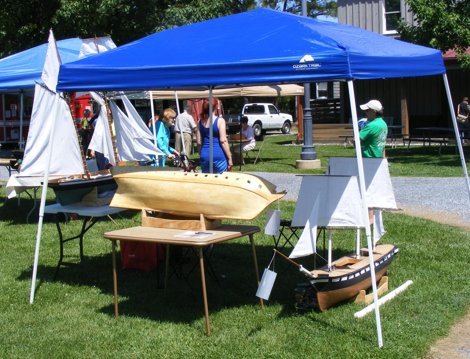
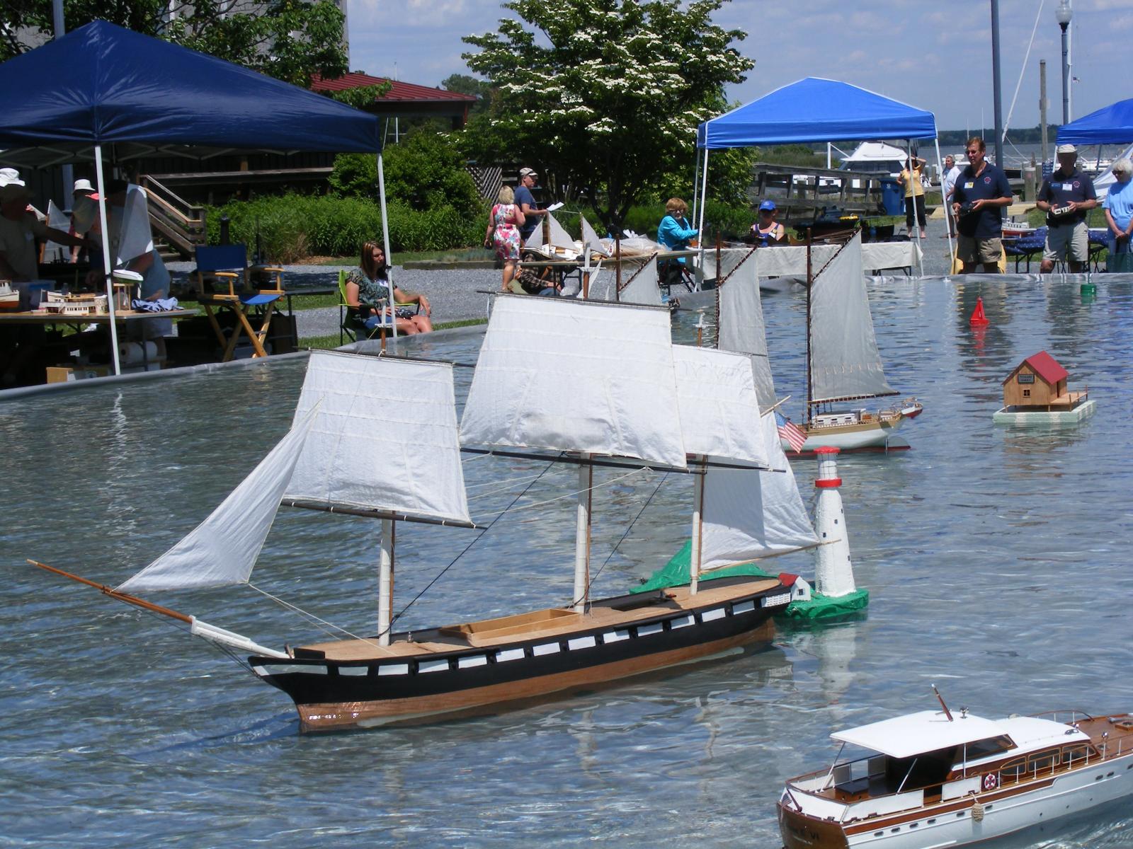
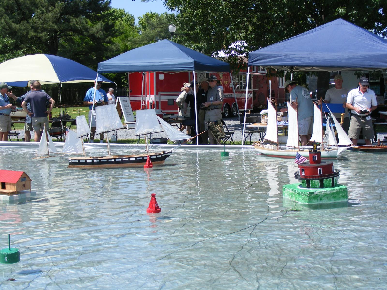
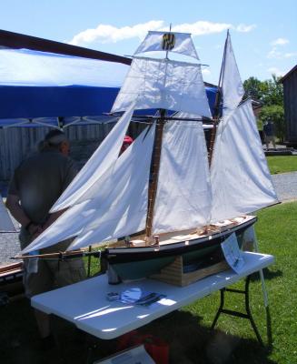
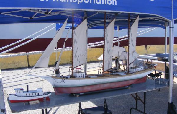
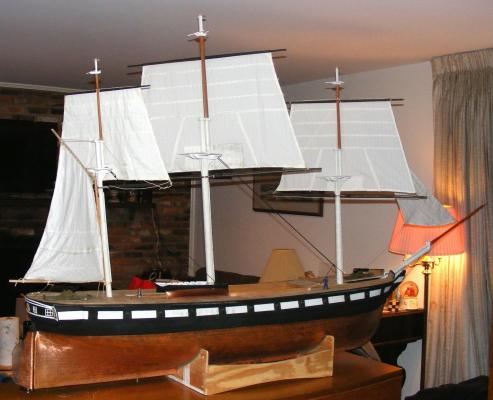
Spent Saturday at the Chesapeake Bay Maritime Museum's Model Boat Expo. This was now my second event of this sort, two weeks after the first, as well as my second visit to the museum since my first in 1979 when I went there aboard the barkentine Gazela Primeiro. All three models went, and I even got a little pop-up gazebo tent, knowing it was going to be quite sunny. Macedonian got quite a bit of attention, to my surprise. Being able to see how she was constructed got a lot of questions about what was used, how it was glued, etc. If I do this any more I think I'll adopt the theme "Don't be afraid to scratch build" as that was what seemed to impress people most - that these were not kits and were built, for the most part, of scrap wood, and materials from the local lumber/hardware stores. Pride didn't sail, though she very much wanted too. I don't have ballast attached to her fin, or her steering set-up as yet, so I took her solely for display. She was very well received because of being a Baltimore Clipper and the 200th anniversary of the War of 1812, which is a major theme running at the museum right now. It was blowing 10-13 mph and gusting a bit as it whipped around the building upwind of us, so I wasn't too sure about putting Constellation in the water, not to mention how crowded with obstacles the pool was, but a friend from another forum put his Ram schooner in and didn't seem to have any trouble, so I went for it. On the pool the wind didn't seem to blow as strong, but it was very flukey and was often doing something different at either end of the pool. none-the-less, Stella made through and actually sailed a bit, though she would often get caught aback just as it was getting fun. I did install a test rig in Constellation to try out a new idea for handling sails with double sheets, like heads'l, etc. I'll delve more into that in some detail later.


- 553 replies
-
- 7
-

-
- sloop of war
- constellation
- (and 3 more)
-
Several posts from #21 through #28 back when the gun ports, stern moldings, paint, and coppering were covered, lost their attached images. I reloaded all of them, and everything looks to be back in order. Looks like Constellation will be getting wet again; I'm taking her and Pride to the Chesapeake Bay Maritime Museum's Model Expo on May 31st.
- 553 replies
-
- 2
-
-
- sloop of war
- constellation
- (and 3 more)
-
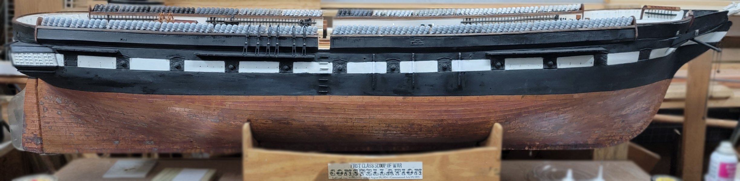
Note: those half port lids are not the type the ship carries now, that are the standard type of the 1850's and later with a vent and two port lights. The half ports described above are plan and simple with the only "hole" being the cut out for the gun.
-
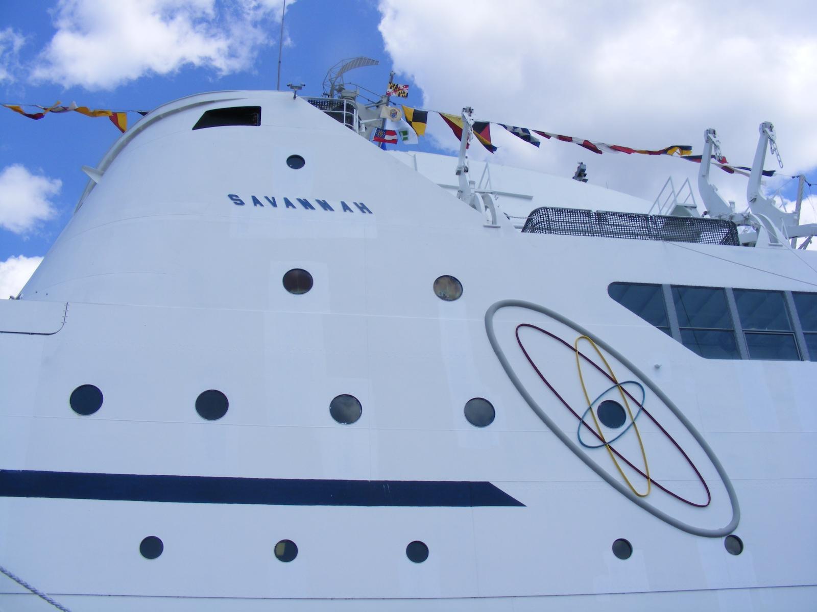
Yes lambsbk, the very same ship. She apparently wasn't bringing in enough money and they decided to rid themselves of her. The city of Savannah had little money or interest either, so she wound up here in Baltimore.
-
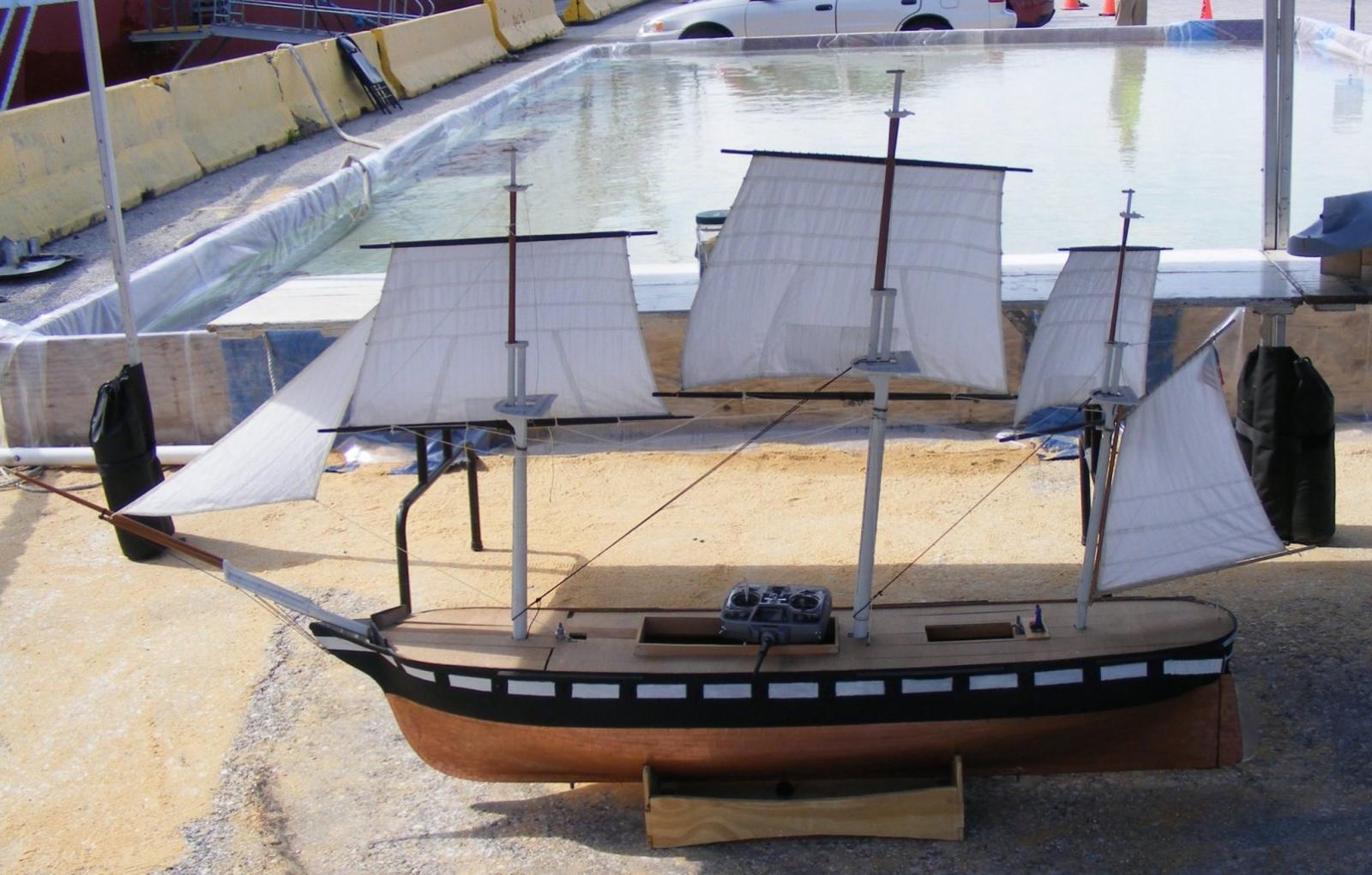
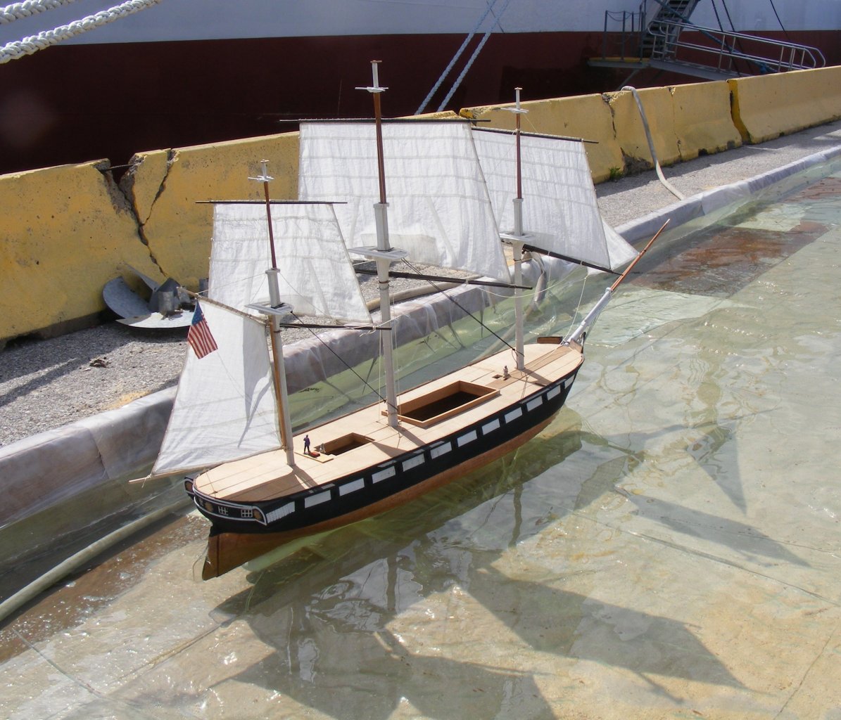
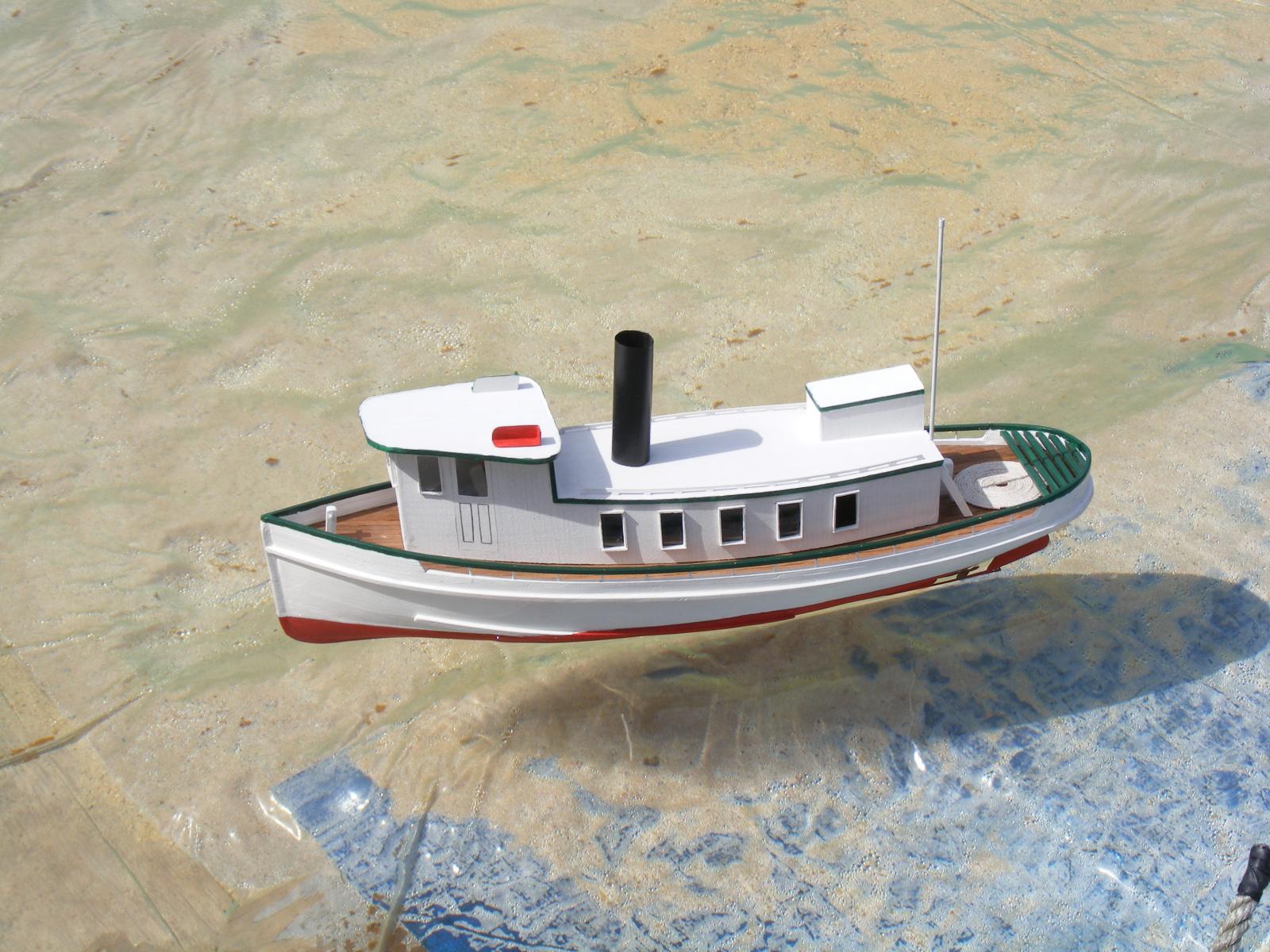
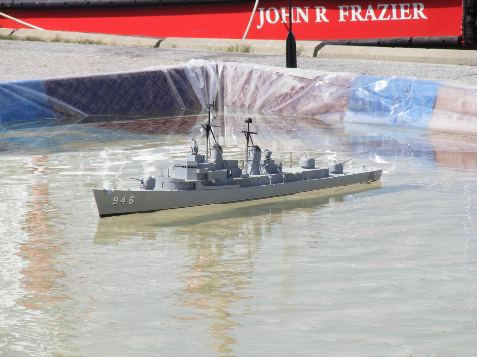
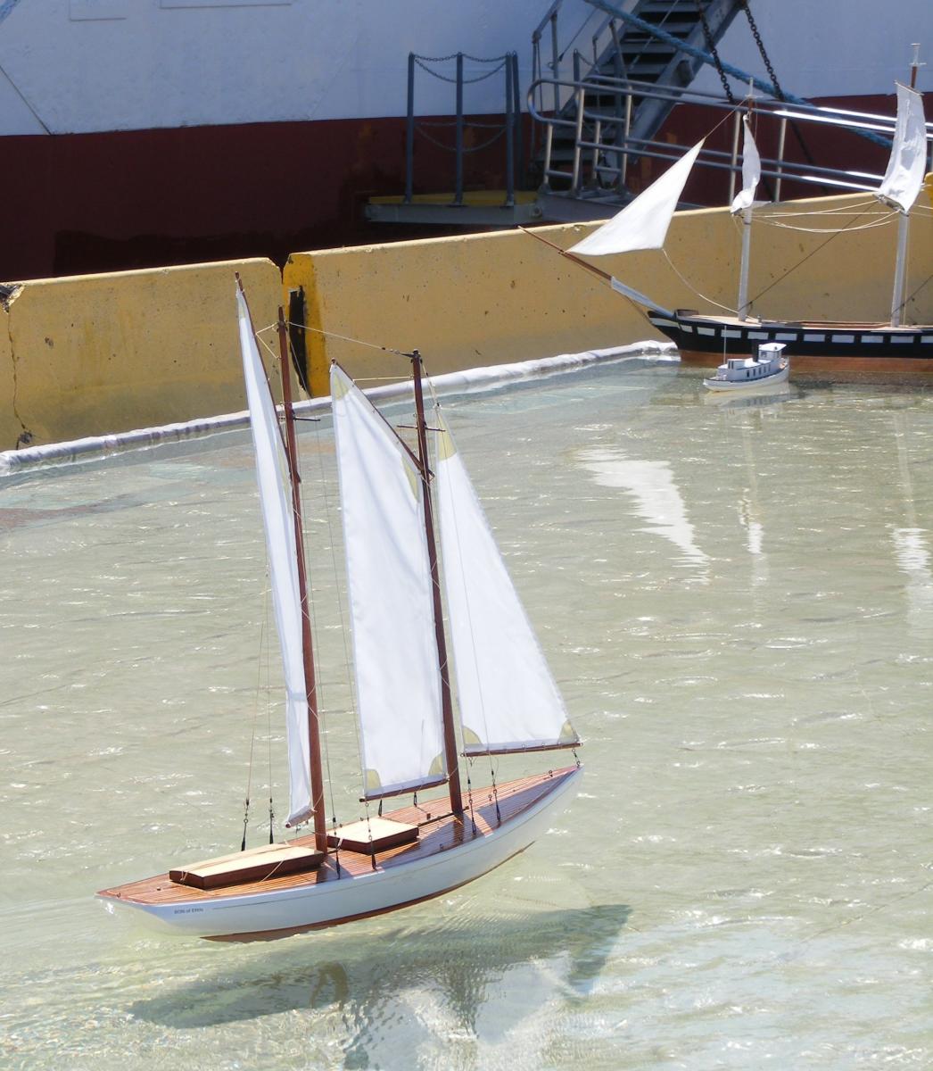
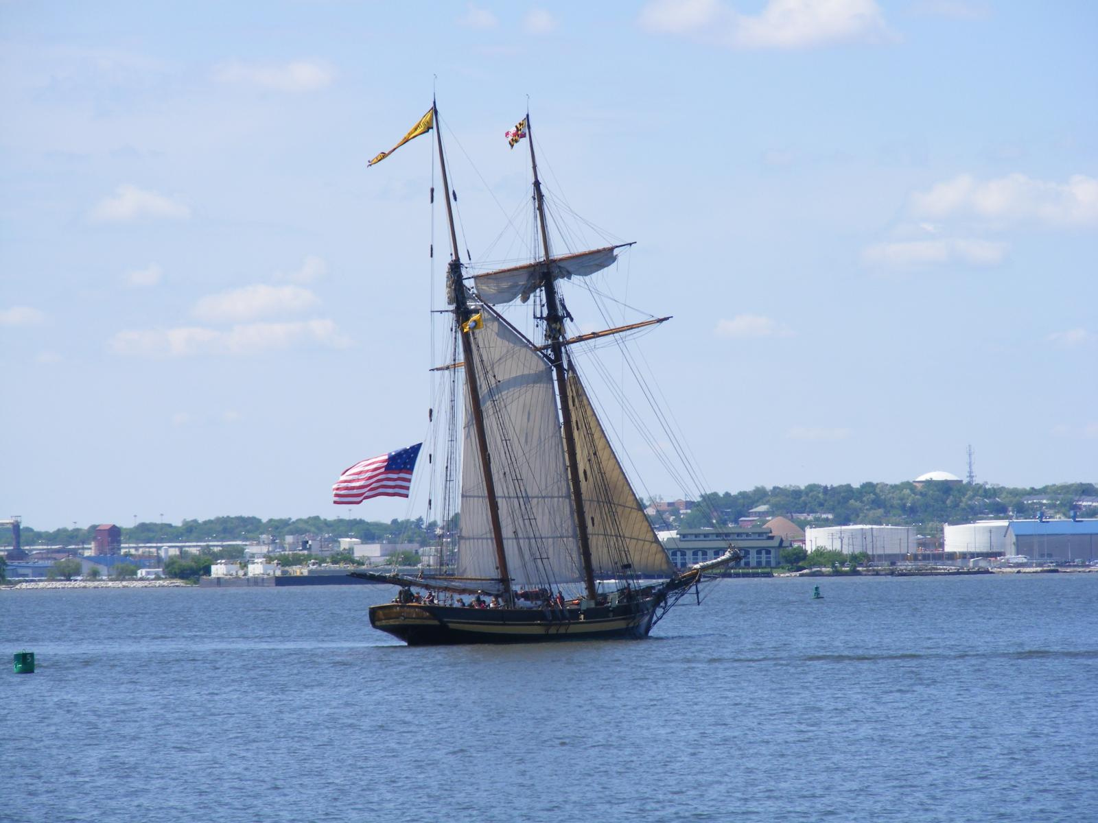
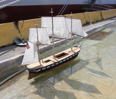
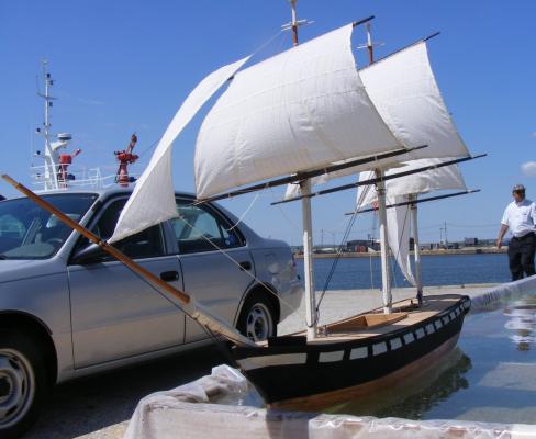
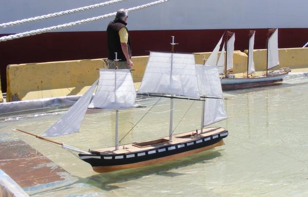
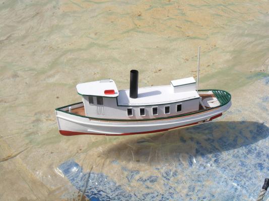
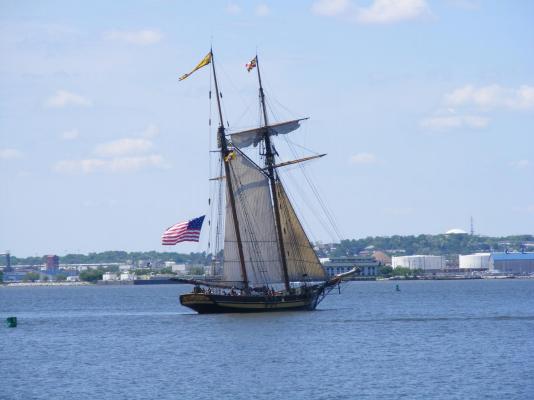
This was my first time publicly displaying a model. It was a learning experience to be sure. The 10 mph wind was more like 15 plus some interesting backwind off the bow flare of the NS Savannah. The 20 x 30 foot pool was no where near enough room for Constellation to actually sail, not to mention it was set-up on a slope and most of it was too shallow. The wind flogged her jury rigged controls so loose so that after a short while, I just tied her up at the windward end. My friend Mark brought his little schooner Son of Erin and she was the belle of the ball, nimbly scooting about the pool, sailed by children and the director of Historic Ships at Baltimore, keepers of the real Constellation. Ultimately, the model got some exposure, especially to some local maritime folks who wanted to see more of it at local port promoting functions. The model, at least, may get a job, if not her builder Don't forget you can click on these images to see larger versions: Packed into a Ford Windstar At the Baltimore Port Expo In the pool Sails filled and nowhere to go "Anchored" Chesapeake Bay Ram Conrad Fuller and tug Delaware, both 1:24 scale. Delaware Forrest Sherman class destroyer in 1:96 scale. Schooner Son of Erin frolicked in the pool Pride of Baltimore II gave free rides NS Savannah


- 553 replies
-
- 7
-
-
- sloop of war
- constellation
- (and 3 more)
-
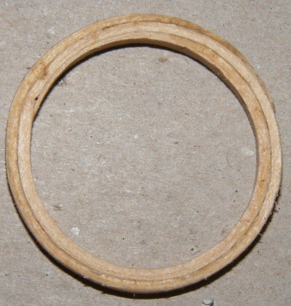
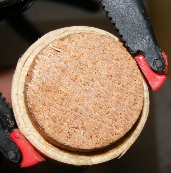
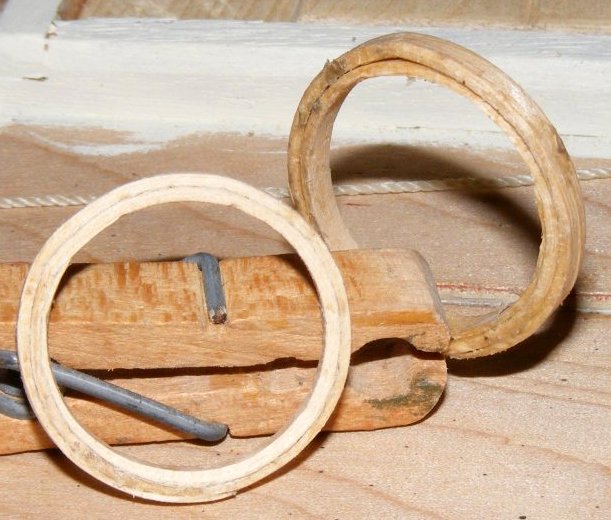
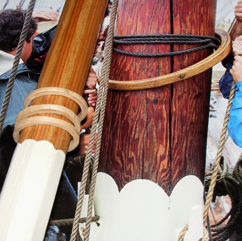
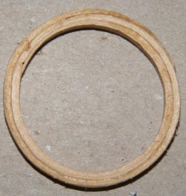
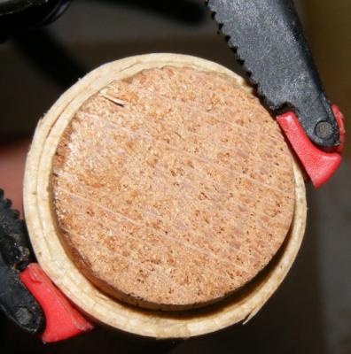
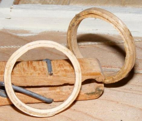
Hoops on schooners are, more often than not, wood. Typically the inside diameter is 1/4 of the mast diameter at the base larger that the mast diameter at the base. These are made of 1/16" thick bass, shaved at the ends to taper to nothing, soaked in hot water and bent around a dowel. When dry they are glued up and put back on the dowel. When set they're stained, sanded, etc, and put on the mast before tabling, hounds, cross-trees, etc are added.

-
It's a device for turning lights on or off by clapping your hands. ok, in this context it's a block on a pivot pin inside the gaff jaws that slides on the mast so the gaff's easier to raise/lower.
-
Well, she's down off the cabinet without breaking anything on her, me, or the house. Everything is jury rigged, I need to rig the braces and sheets yet. The electronics have been tested and the batteries charged. I also need to run the steering cables and she'll be ready to sail Sunday. I wish I had her t'gallant masts made, but, them's the brakes.

- 553 replies
-
- 4
-
-
- sloop of war
- constellation
- (and 3 more)
-
Every ship, I'm sure, has been lamented as a "wet ship." Even Constellation on her first trip to the Med in 1855 was said to be wet and took water through her ports despite split lids being caulked - on a brand new ship yet. Taking water through the ports doesn't confirm the absence of port lids unless it says there were no port lids. The US wasn't suffering from material shortages that would require such measures as foregoing port lids. True, her original copper was imported because Revere wasn't set up to produce what was needed, but this ship met the Guerriere 15 years into her life. In 15 years she was never fitted with port lids? And what about the other frigates? Just Constitution, a New England built ship, had no lids. It's an illogical argument supported by sketchy evidence at best. This sort of reasoning is like saying Napoleon ALWAYS had his hand in his coat, because a couple of portraits showed him posed that way.
-
I once read a book on Civil War cavalry that cited some items about how the men wore and carried their arms and equipment that were ridiculously impractical and sometimes impossible. What was painfully obvious to someone that has reenacted Civil War cavalry on horseback for a couple of decades was - the folks that write books seldom have any practical experience in what they are writing about. I firmly believe this is the case with Constitution's gunport lids, or lack of them. It makes no sense to any one that's sailed anything from a dinghy to a full-rigged ship that a line of 15 or so 3 foot square holes would be left open in the sides of a ship supposed to operate in the Atlantic Ocean - and subs had screen doors too. I suggest the Hull model at some point lost it's lids, or, as isn't uncommon in folk art, which is what the Hull model is, the maker simply didn't bother to make and install them, probably to cut a corner due to time constraints. Paintings, well, there's a plethora of paintings of ships that claim to have been done under the direction of some authority that you'd think would know but are still known to be incorrect or misrepresent specific details; color of a stripe, deck arrangement, flags flown, order of battle, comparative size of vessels, etc etc etc. Why would Constitution not have port lids? If she didn't, why aren't there log entries lamenting the water being shipped in storms for the lack of them, or the snow blowing in during her winter stays in Boston during the "mini-ice age" of the early 1800's? It's not like they were some newfangled invention untrusted by crusty old salts, they've been around for a long time.
-
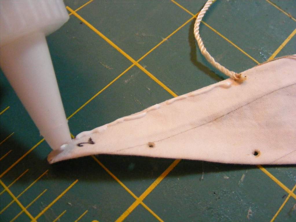
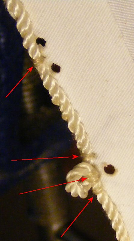
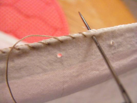
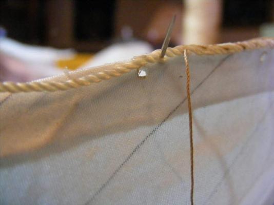
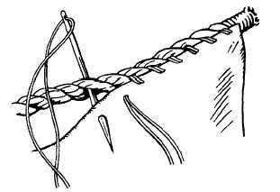
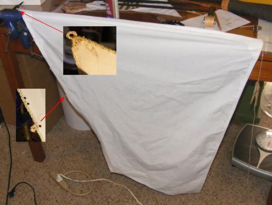
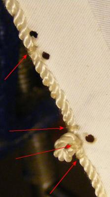
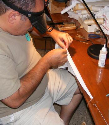
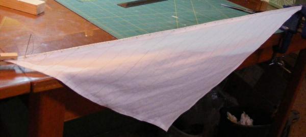
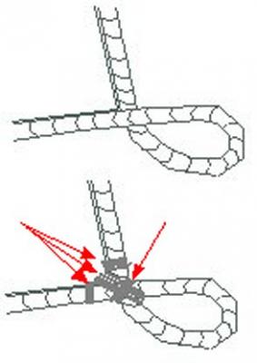
Real bolt ropes are sewn on in a particular way to get the most strength via surface contact. They aren't hanging on the edge of the cloth, but are laid on the cloth on one side of the sail and stitched between two strands of the rope and through a third strand. On my sails, I cheat a little. I use a bead of fabric glue to reenforce the attachment of the bolt rope to the sail and though it's stitched in the same manner, I skip 2 or 3 strands each stitch. The fabric glue lets you get away with this, and the stiches almost disappear into the bolt rope's strands. The sail itself is anchored at one end with a weighted line off the other end. This keeps the edge taught without stretching the sail and allows you to work without it flopping all around uncontrollably. I put about a 2 inch bead of glue down and stitch that much. Nice thing is you can leave this, take a break, and come back to it later. Yes, it is tedious, and I am not known for my patience. Being able to walk away now and then got me through 7 sails so far on Constellation (10 more to go) and 8 sails on Pride without getting myself on the evening news. I use DuPont Supplex cloth for sails. It's made for outdoor wear and is water and UV resistant. It's very light and forms nicely on the model. It doesn't shrink or stretch excessively and is stain resistant. A very nice thing about using a synthetic fabric is it melts. I used a pointed soldering iron tip to make grommets for reef points, lacing holes, and any other holes needed in the sail. This makes nice sealed edge holes that won't open up or cause a run in the sail. I made cringles and eyes in the bolt rope by taking a turn around a round wooden toothpick to hold the eye open as I stitch past it. Every eye is tightly lashed in it's opening and on either side as the bolt rope is stitched on. I opted to draw on the sail cloth panel seams on my sails with a .003 permanent ink pen, so I'm not beyond cutting corners myself Victor Yancovitch also used Supplex for his sails on Royal William and sewed the panel seams. It took a lot of trial and error over a couple of weeks, with a lot of wasted cloth before he and his wife finally got it sorted out. He also machine stitched on his bolt ropes, and after the model was sailed he found several places where the bolt-rope had slipped through the stitching and had to be hand seized in various placed to prevent that happening again. Again, I only offer you a view of the road some have been down already - the route you take is up to you.


-
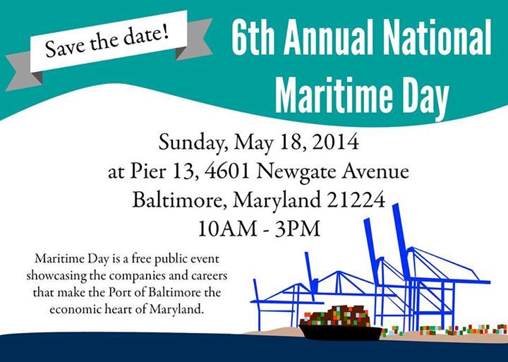
I've been invited to take Constellation to National Maritime Day on May 18th. They're setting up a 56 x 24 foot "pond" for RC models at pier 13 where the NS Savannah is docked. So, as I get Constellation ready for her second sail, I'll post updates here along with pictures and a report after the event.
- 553 replies
-
- 4
-
-
- sloop of war
- constellation
- (and 3 more)
-
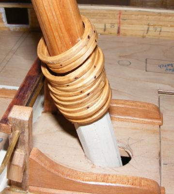
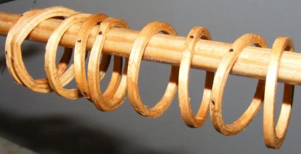
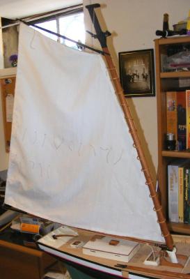
Those hoops look a bit snug there, they should be a little large so they can travel easily and not distort the sail by binding.
-
Bravo! Bravo!
-
I'd look at the photos of the actual boats - they often fill in where plans fall short.
-
That flying jib seems a bit high
-
How are you dealing with ballast?
-
So, I'm at a church yard sale back in October and come across a set of some 15 books about a character named Nathanial Drinkwater. At $5 for the lot I figured I couldn't go wrong, so... So far I'm well into the 4th book. The author is an historian and has been to sea; he's has done good research to construct his stories, though it tends to read much like a history book. It's a decent read, the language and nautical jargon is correct, and I've had no trouble picturing what happening by his descriptions. I can't say I really "care" for this fellow, all these stories seem to copy Forester and this one's no exception. Even less than a quarter of the way through the series, I have to say it was well worth $5.
-
He found me and the links are in my signature.
-
Bravo! I'm always on the lookout for ingenious ways to handle sails with the least amount of cost, tools, and engineering.
-
I build my hulls in a sort of Hahn method, that is the frames are extended up to a common line and fastened to a building base board until the hull is planked. This backbone building board keeps everything aligned until there's enough structure to do it itself. You might add extensions to the frames to accomplish that, and unless it's a horseshoe, you might still use that keel you have.