

Navis Factorem
-
Posts
240 -
Joined
-
Last visited
Content Type
Profiles
Forums
Gallery
Events
Posts posted by Navis Factorem
-
-
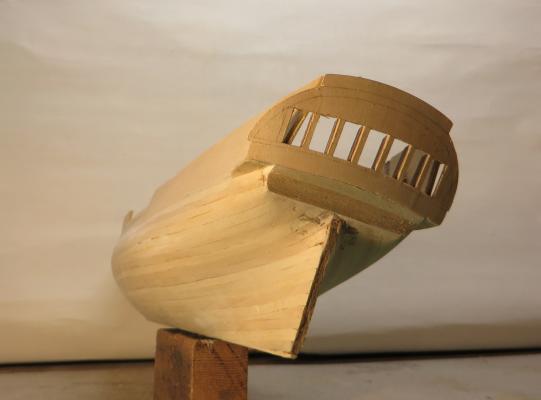
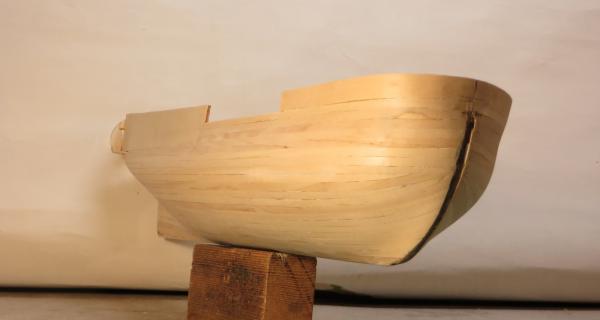
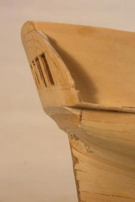
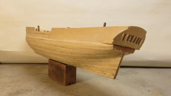
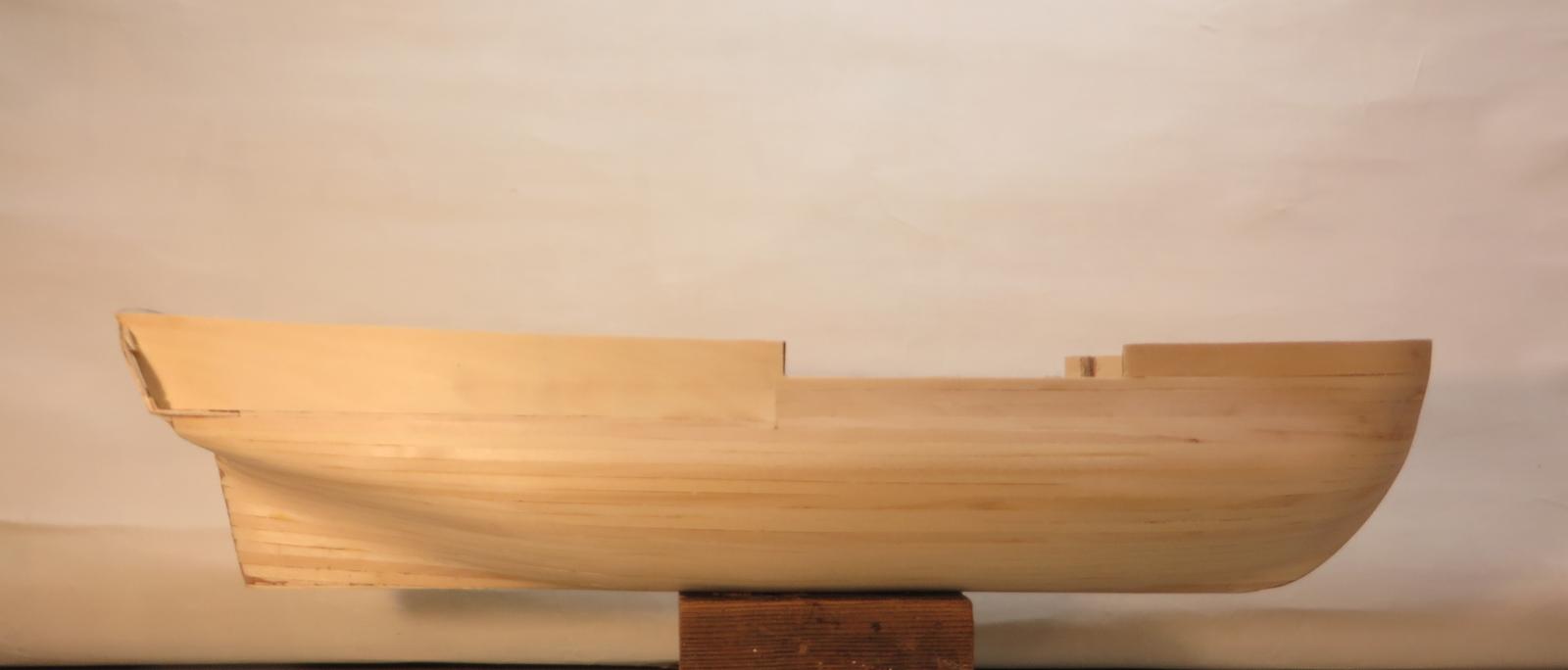
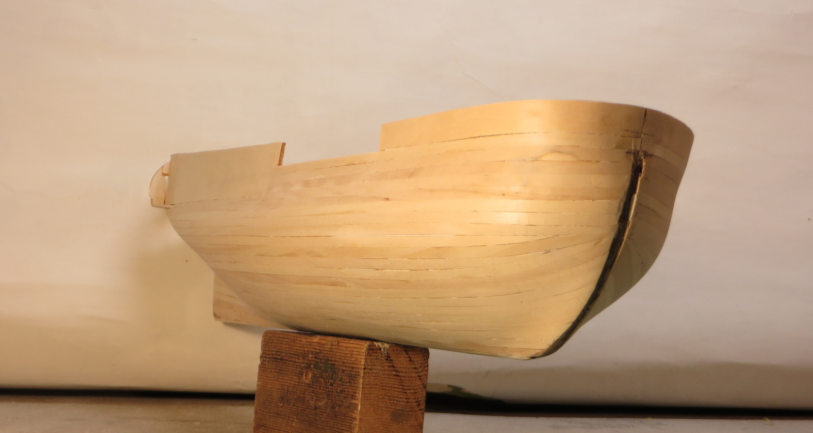
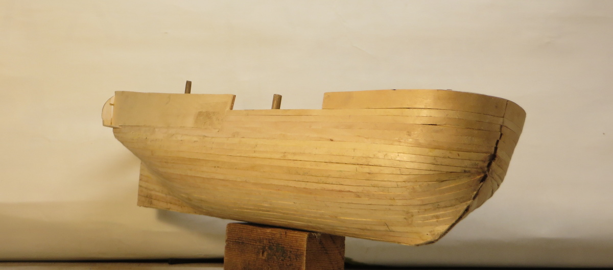
The first plank layer has now been smoothed and the stern section below the windows as been added.
Now to shape and fit the stern post, keel and cutwater before starting on the top plank layer.
Cheers,
David.

- mtaylor, Elmer Cornish, canoe21 and 7 others
-
 10
10
-
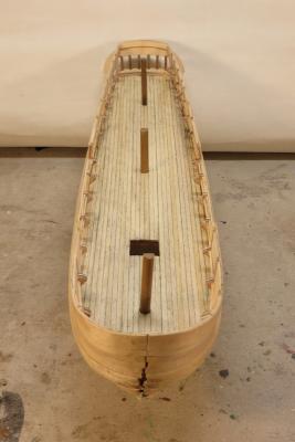
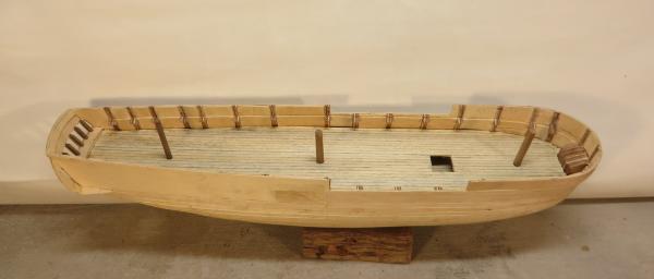
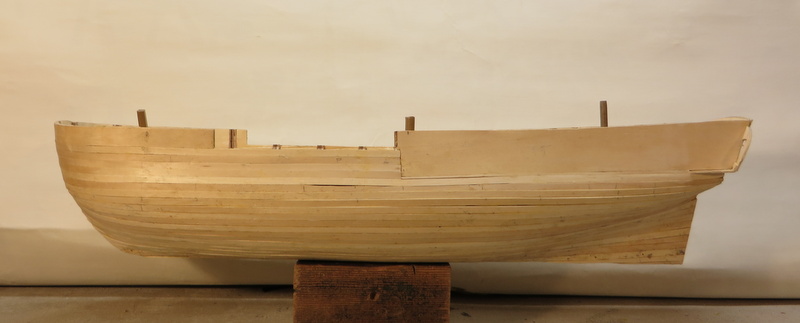
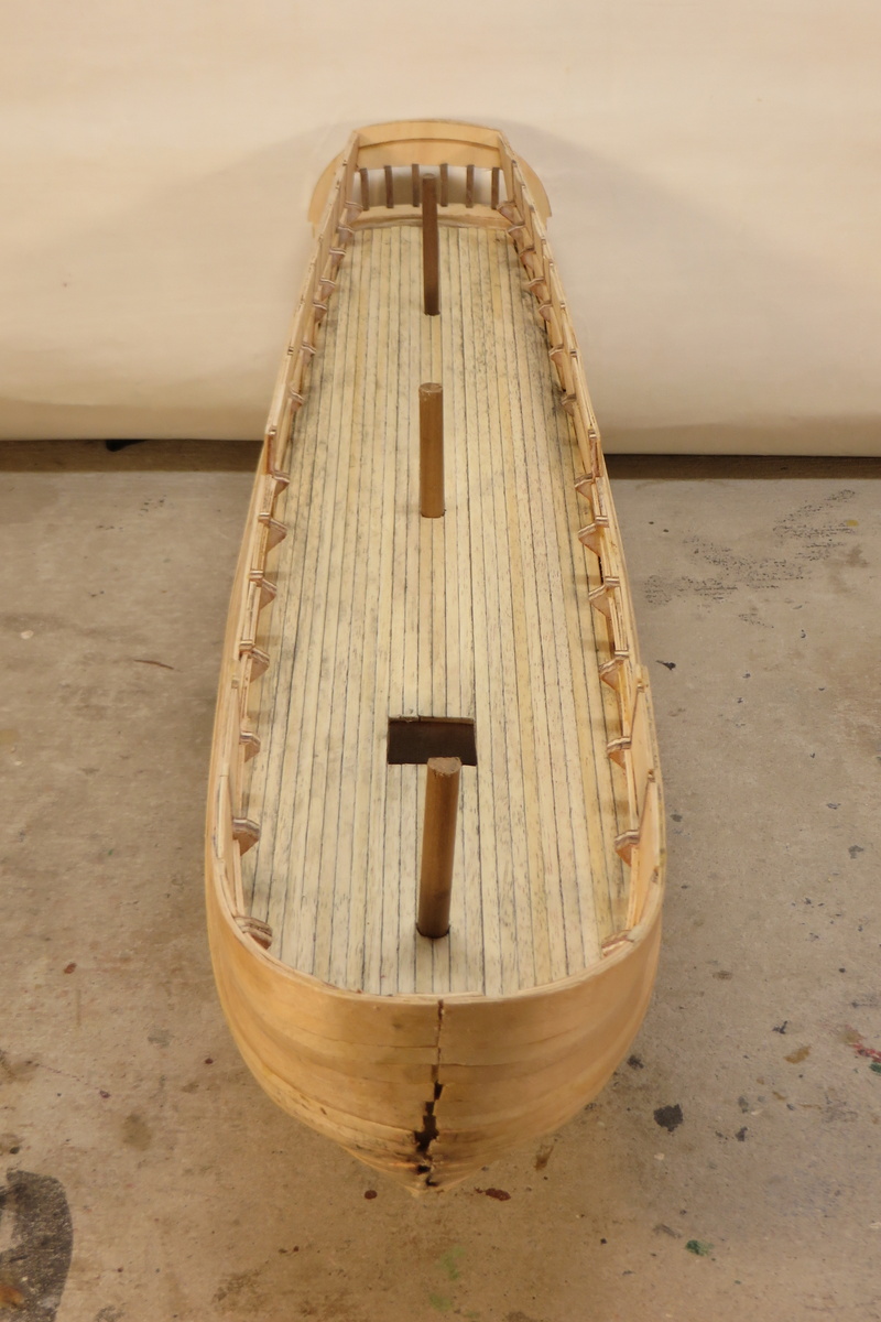
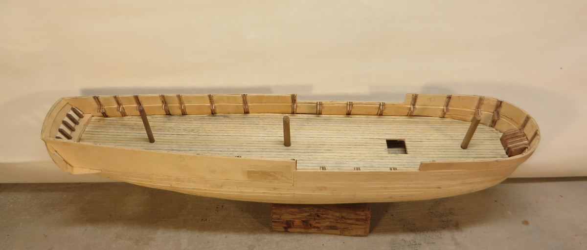
Time for an update.
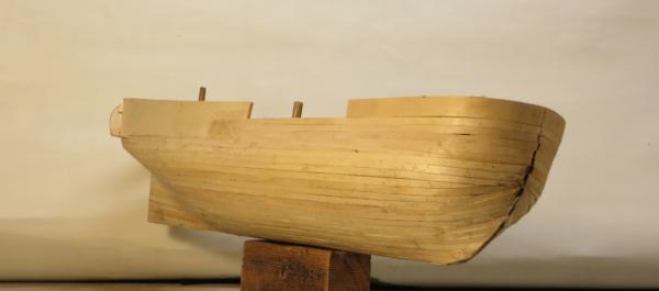
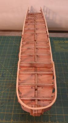
The hull under planking layer is now complete and ready for sanding to achieve the final shape before fixing the top plank layer.
While I was doing the planking I also thickened up the hull sides and the bulwarks so that the gun ports and other penetrations will be the right depth. I do not intend cutting the gun ports etc until all planking is complete.
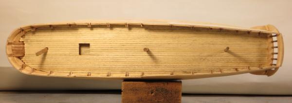
I have also fitted the deck planking to the main deck and will now start adding the deck furniture on this level. The plank joints and trenails will be added when the holes for the hatches etc have been established.
The single penetration through the main deck is for the forward companionway as this is the only hatch that can be seen into. I have already planked the deck at the lower level.
I think that the hull shape looks OK. As I was shaping the hull I came to realize how the hull shape of a frigate is different to the hull shape of a transport based ship like the Bounty. The frigate is much narrower and the resulting tendency to roll must have made them wicked to inhabit in a cross sea. Also the main deck width doesn't vary much in the ship's length and is quite wide at the stern, presumably to work best as a gun platform.
Cheers,
David.

-
Hi,
Just finished looking through your log, lovely build.
I am building the Surprise of Master & Commander fame and one of the tasks will be to build the ships boats which at 1:75 scale will be about 80-90mm long so I am interested in your small hull build. I will be doing something similar in timber, working over formers which are removed when planking is complete.
Interestingly I live in a 1920's house which has a pretty original looking brass name plate on the front "Ingomar". Mr Google is not very forthcoming about the meaning, have you come across any info about the name?
Cheers,
David.
-
Hi Bindy,
Still plenty of room in the front stalls, red wine lubrication can sometimes certainly help with those awkward moments.
Once I had decided to build the surprise I did a bit of research into options, one was the Mamoli kit as a start and then a bit of kit bashing similar to my Bounty build where the McKay book was the inspiration. I did consider some of the other Surprise kits but at 1:48 or similar scales the end product is huge, certainly far too big for the spaces I have in my home for display. At the end of the day I just decided to get a good book with original admiralty based drawings and go from there with 1:75 as the scale as this produces a model at about a size I can manage.
I have searched online for a book for the Surprise similar to McKay's "The Anatomy of the Ship The Bounty" but have not been able to find anything. What sort of research material have you found for your Surprise build? The Hunt Lavery book on the Surprise is OK and its drawings are the basis for my build but it lacks the terrific detail drawings of the AoTS book.
A valuable resource I have for the rigging bit of the Surprise build is the Lennarth Petersson book "Rigging Period Ship Models". The book is full of detailed drawings of the rigging of a frigate of about the same time as the Surprise so will be a great guide.
I noticed in your log that you were a bit awed by the 4 rigging cords that came with the kit. If you want to get anything like accurate with the rig you may need a few more thicknesses. My Bounty build includes about 20 different cord sizes in 2 colours including the fattest at 1.4mm diameter for the main stay which I spun out of 24 lengths of sewing thread.
When some more pics of your build appear on your log I will watch with interest.
Cheers,
David.
-
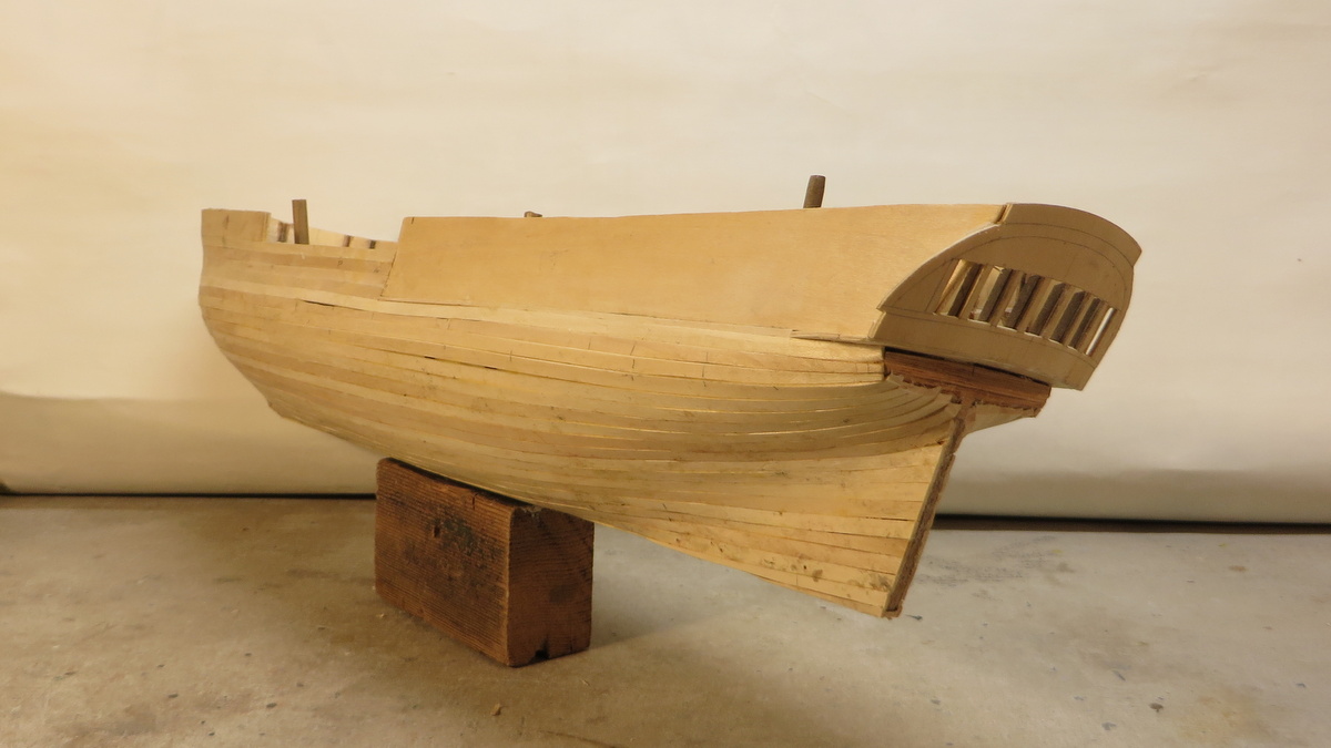
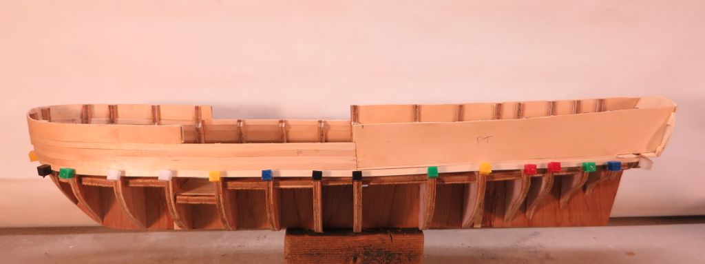
Hull planking stage 1
After a bit of a break construction has restarted.
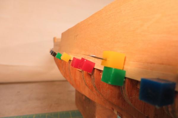
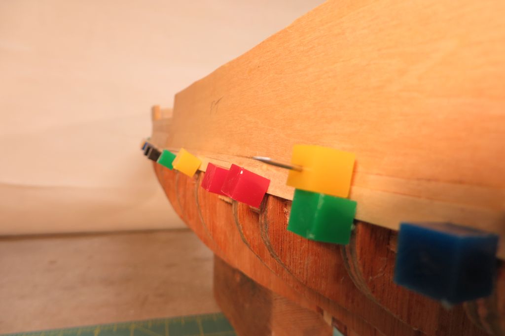
The upper part of the first plank layer has been completed. This has been done before the lower part of the frames are faired at the stern mainly to protect the top of the ribs where they are quite thin and easy to break. (A couple have already been damaged.) The upper planking should enable work to be done on the bottom without breaking any more. The single curve sections of the bulwarks are 1.5mm ply and the planking below is 1.5mm lime wood which is fairly soft and easy to bend.
I have tried a new way of clamping planks in place while the glue dries. Previously I have used small planking screws that have a plastic knurled part and a small metal screw and a little flap that presses on the plank. I find these quite difficult to screw in and for most of them the metal screw now rotates in the plastic bit making them fairly useless. I have tried the small spherical headed map pins but they don't really clamp the planks. I nailed many of the planks on the Bounty but this is time consuming and you can end up with nails just where you don't want them. Wandering through a local stationery store I came across these cube headed pins and thought I would give them a go. They work really well! The pin anchors well in the ply ribs and the head clamps the planks in position. They take a bit of pushing in and I do this with a piece of scrap ply. When pushing in round headed pins previously I had a pin shaft come through the head and punch a neat hole in the end of my thumb! That REALLY hurt so I don't take any chances now.
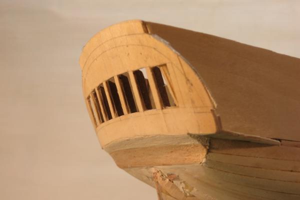
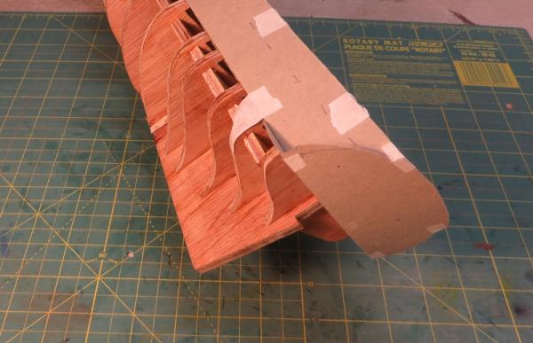
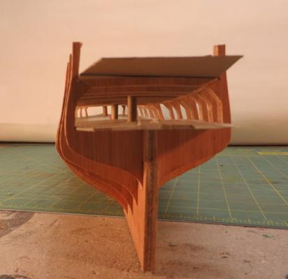
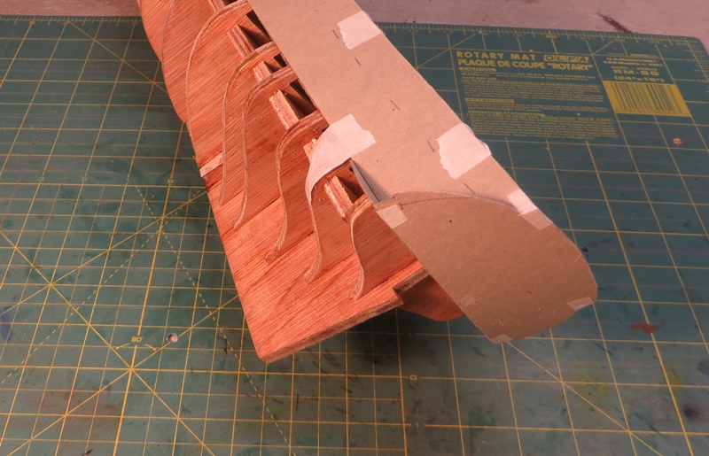
The cardboard stern elements have been converted into ply and fixed in place. I think that working from the outside of the curved stern to the inside should enable a light stern framing compared with what I have seen in kit constructions and allow the "see through" look that I want for the stern windows.
Cheers,
David.

-
Thanks Jason, the drawings I have don't show a step at the forecastle either.
Does anyone have any knowledge of the 2 piece vs 1 piece gun port covers?
Cheers, David.
-
Question about what looks like a step in the deck.
The drawings seem to show a step in the upper deck where the gangways meet the quarterdeck. It looks like it occurs at about the centre line of the access steps. Can anyone please confirm that this is the case?
Also, the side view of the exterior of the hull clearly shows 2 piece gun port covers. This is the only place I have seen this detail, all the Geoff Hunt pics show 1 piece covers. Can anyone shed any light on this please.
Cheers,
David.

- canoe21 and Elmer Cornish
-
2
-
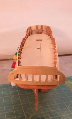
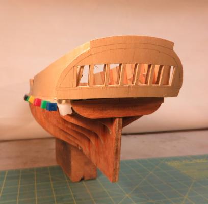
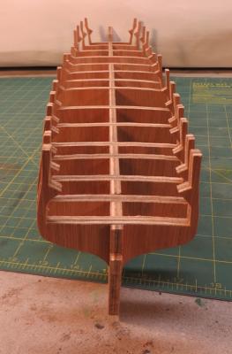
Greetings all,
The shipyard hasn't been too busy lately, some travelling has been taking up time.
However, some progress has been made and I should be able to make lots more dust soon.
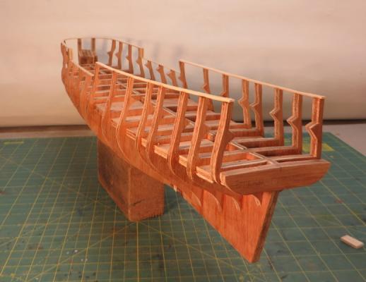
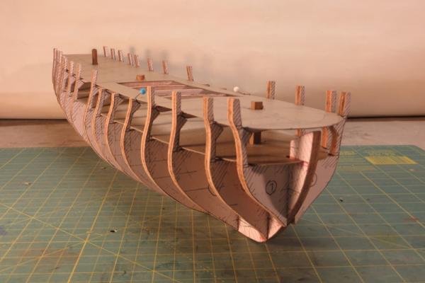
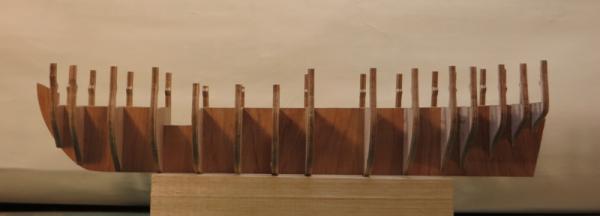
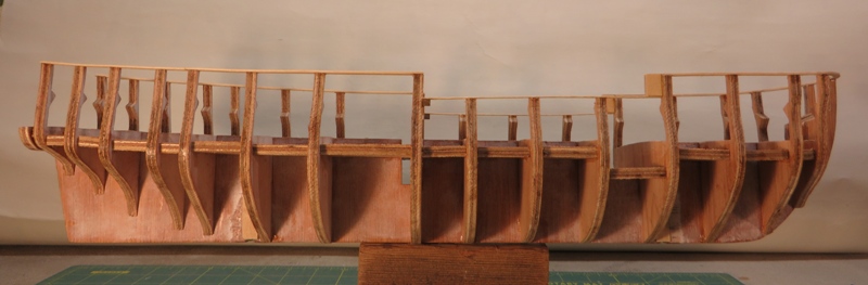
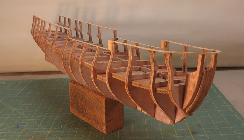
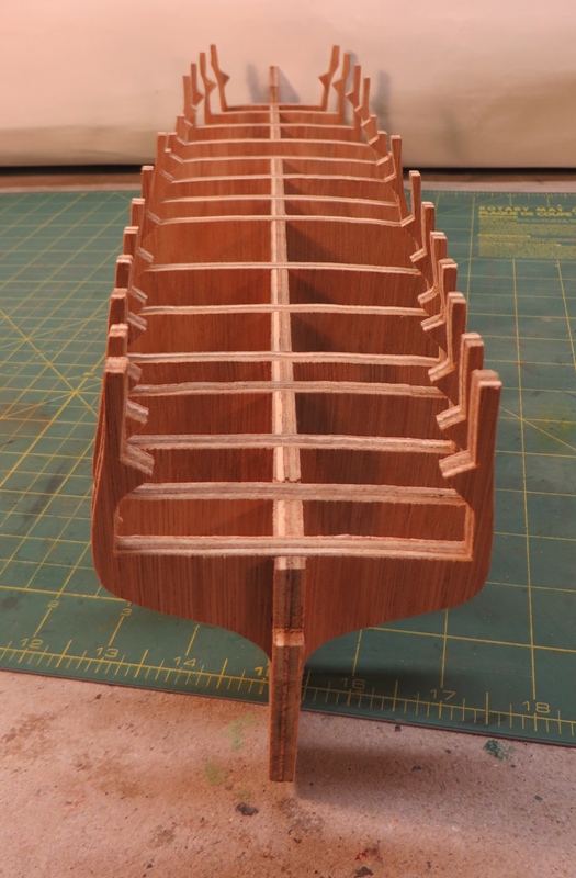
The skeleton has been glued and reinforced to enable the fairing process to start. I fitted a false deck to stabilize the frames lengthways and fixed false rails to the tops of the frames to give them more strength. Hopefully I won't break any of the ribs.
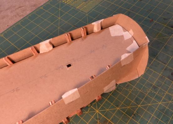
I made up false decks, bulwarks and stern from card so I could check fit and to ensure that the basic shapes for the stern and the quarter galleries look right. I will frame up the stern with the window openings once the fairing is complete and the stern bulwarks are in place.The false bulwarks and stern base will made from 1.5mm ply. The gun deck will be continuous with the bottom of the quarter galleries to keep the lines right.
Cheers,
David.


- GuntherMT, egkb, Wishmaster and 10 others
-
13
-
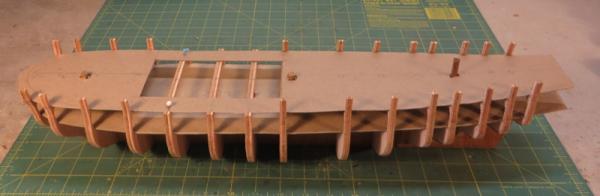
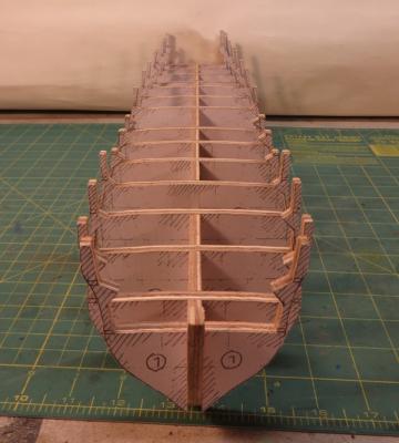
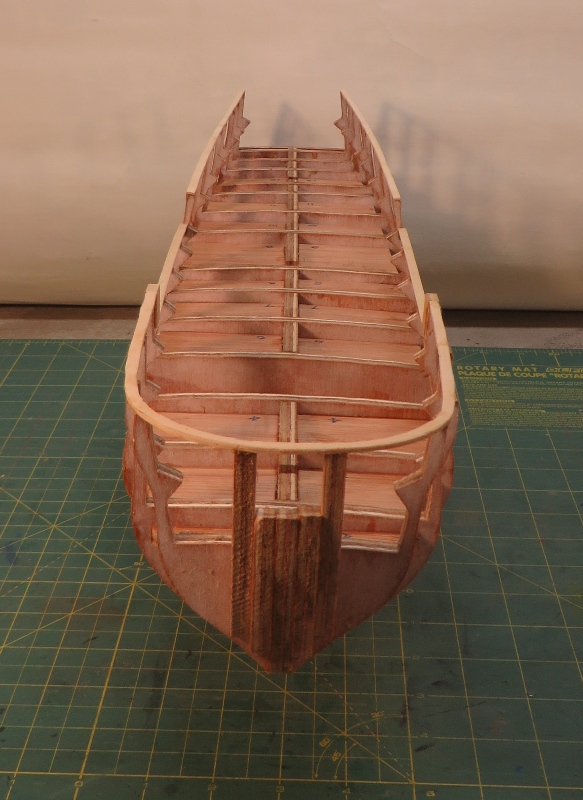
Still doing dry assembly to make sure the parts fit OK. I have cut the slots for the masts and fitted captive nuts for threaded rod for the final mounting on pedestals.
Before gluing the bulkheads I have made up cardboard templates for the decks to make sure they will locate on the bulkheads OK. The view through the stern olong the gun deck is interesting, I am still a bit undecided about how much of the interior cabin bulkheads to include in the build. I will be glazing the stern windows so it might be nice to look the length of the "clean sweep".
Now to start gluing.
Cheers,
David.
- gjdale, GuntherMT, aviaamator and 9 others
-
12
-
Thanks for the comments Doug, I hope you enjoy building the Bounty as much as I did.
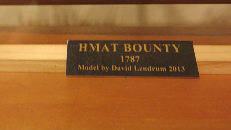
Final post for my Bounty build, I have collected the acrylic case, made up the big base, and the name plate and very carefully slipped the case on. I had a 290mm piece of shelving that I used for the base so the clearance inside the 4.5mm thick acrylic is 281mm. The main yard stunsail booms are 275mm to the ends. A VERY neat fit and the booms clear the case on both sides.
Cheers,
David.


- GrandpaPhil, GuntherMT and cristikc
-
3
-
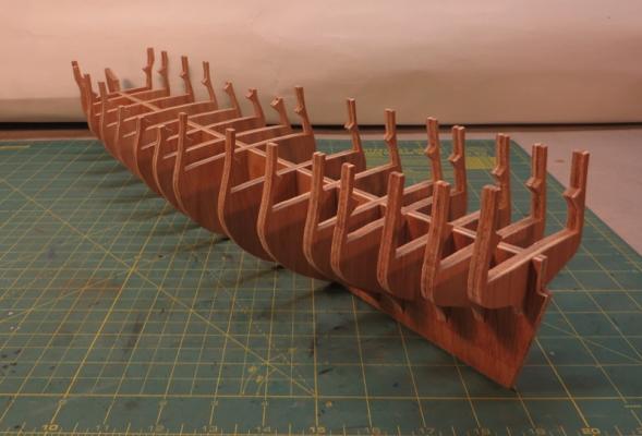
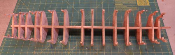
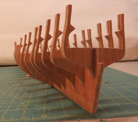
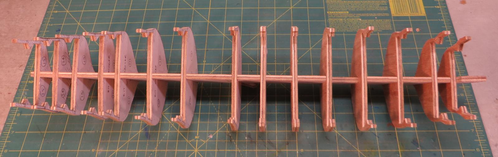
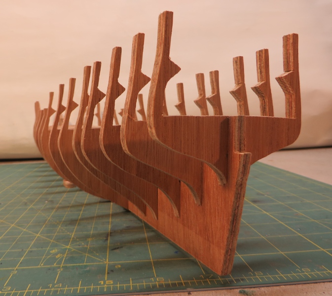
The scroll saw has been whirring away and significant amounts of sawdust generated, fortunately most of it disappearing down the vacuum cleaner pipe that attaches to the front of the saw.
The pics are of the first dry assembly, I am quite surprised at how well the bits fitted together, there was only a small amount of shaping required to get a nice firm friction fit.
Most of the bulkheads are pretty much the right shape, there is going to be a small amount of reshaping of some. The position of some of the L & H original station lines has been changed so that the bulkheads avoid gun ports. I didn't want to cutting gun ports through the ply.
So far I have only cut out the well for the foreward companionway which wil be clearly visible through the waist. Two significant things yet to be cut are the mast slots and the slots with the captive nuts for the final fixing to base pedestals. I didn't do this for the Bounty and drilling and screwing up into the keel of the finished model wasn't much fun. Live and learn.
Once the false keel and the bulkheads are the right shape and in the right place I will glue fix and then insert a false reinforcing deck between the bulkheads to keep everything square and to make a strong structure for the fairing process. As I have used 6mm ply and the final keel, cutwater and stern post are 5mm thick this shouldn't be too difficult.
Cheers,
David.
-
The bulkhead and false keel diagrams have been copied and glued to 6mm Marie ply. I have repositioned bhs 1 & 2 forward as suggestion, thanks Colin.
Now to try out the scroll saw.
Cheers,
David.

- Jason, mtaylor, Elmer Cornish and 3 others
-
6
-
Thanks Colin and Russ,
I had started looking online to buy Steel but the online version is a great resource. This fills in lots of blanks.
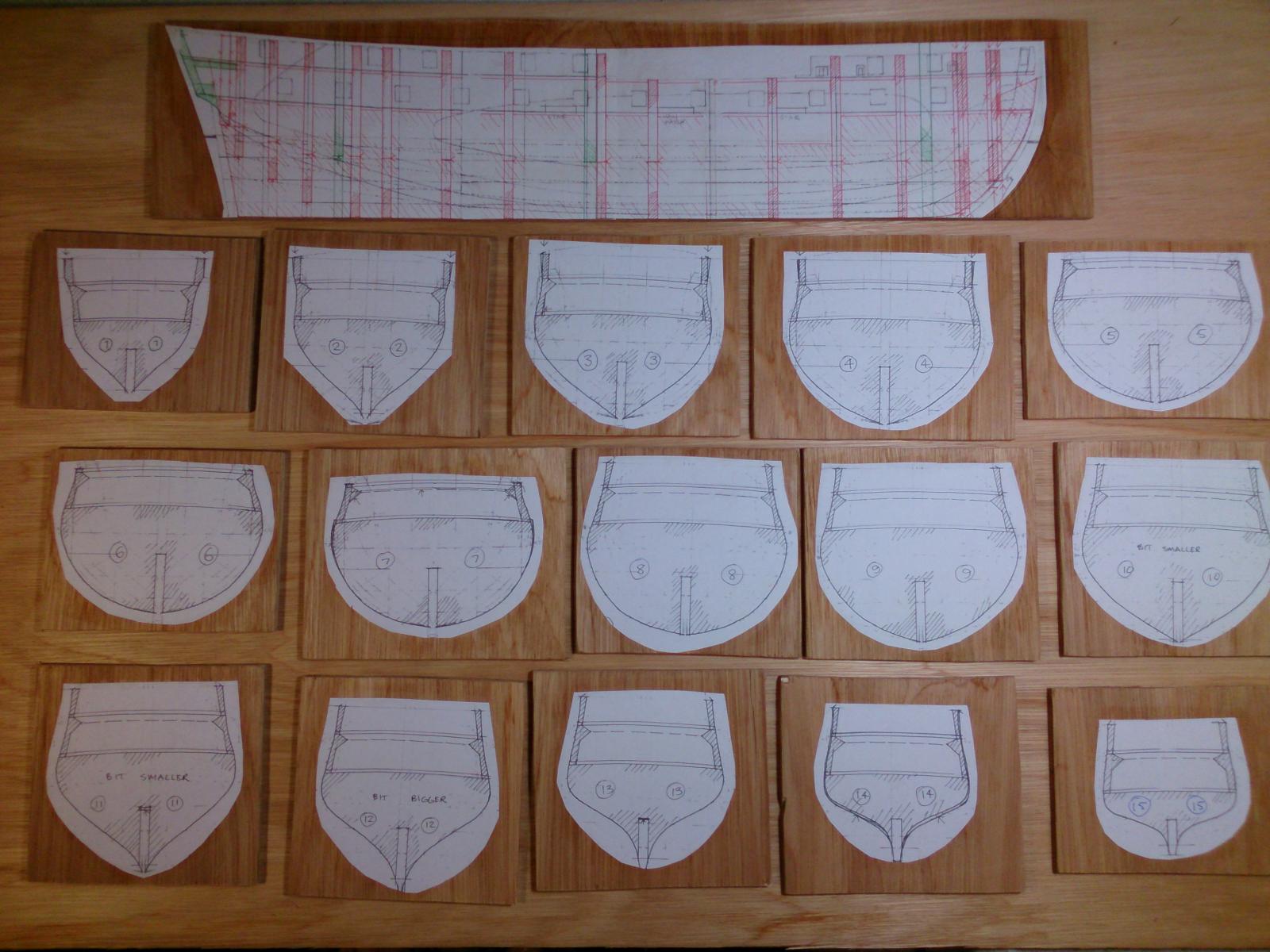
I have completed the layout for the false keel and the bulkheads. Now to glue them to ply and start cutting.
Another resource I have found helpful is the JoTika site for the development of their Surprise kit. It can be found here:
http://www.jotika-ltd.com/Pages/1024768/Surprise_Front.htm
There are some good tips here but I wasn't very happy with their stern treatment with all the frames completely blocking the view along the gun deck. I am going to try something different. I will work up the solution in detail once I have made up a workable frame. (IF I can make up a workable frame!)
The L & H drawings shows grid lines for the cross sections and I initially thought I would make up the bulkheads on these lines but some of them went through gun ports on the gun deck so I had to move some of the bulkhead positions.
I have set the mast positions with the slots vertical for the moment. I am still trying to find what the mast rakes may have been. If I can't find anything else I will use the same rakes as the Bounty, foremast vertical, main raked back 2deg, mizzen raked back 4deg.
I have yet to try my scroll saw, the first efforts should be interesting! I will be making copies of all the bulkhead layouts so I can recut if (WHEN) I don't suceed.
This is the false keel layout and some of the bulkhead layouts:
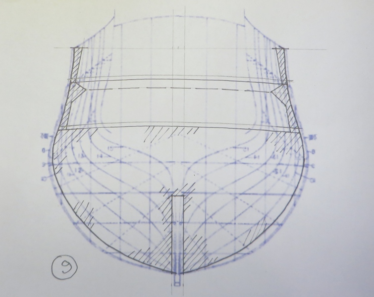
The bulkhead at grid 9:

Cheers,
David.
- mtaylor, Elmer Cornish, canoe21 and 1 other
-
4
-
Hi Brian,
The Lavery & Hudson book is a good resource but my view is that it only goes part way to providing enough info to scratch build the Surprise.
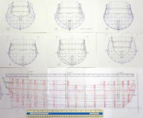
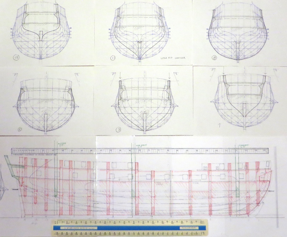
I have worked up a set of hull profiles and a long section of the hull at 1:75 and soon I will glue these to 6mm ply and start cutting out the false keel and the bulkheads. To get to this point it has taken quite a few hours as I had to scan the drawings from Lavery & Hudson then convert the scans into bits that would paste into Word documents for printing at the right scale. I think I can build a resonable hull.
There is a problem with the L & H book as it does not include many detail drawings of mast and spar construction. It does have mast and spar sizes which I have converted to 1:75.
Another resource I am using is Lennarth Petersson "Rigging Period Ship Models" which is based on the rig for an English frigate so the rig for the Surprise would be very similar. This book also has diagrams for some hull and mast details. It does not include the rope sizes for which I will need a source.
My Bounty build started life as an Amati kit but was substantially modified as I went along, mainly using McKay's "Anatomy of the Ship the Bounty". This was a terrific resource, full of good diagrams to get details right and it also included a complete schedule of all the ropes and their sizes. At the end of my build I must have used about 20 different rope diameters including making my own 1.4mm dia main stay spun from 24 strands of sewing thread.
So another possibility for Surprise is to find a book like the Bounty AoTS that includes all this detail. I haven't done much looking yet.
If all else fails the final fallback option (perhaps it should be the FIRST option) is to buy a set of plans for the Surprise from Modeller's Shipyard who include in their online catalogue the Mamoli Surprise plans at 1:75 for $89.15.
Cheers,
David.
-
Raking of the masts.
I am setting out the false keel and a key element is the slots to carry the feet of the masts.
With the limited information I have I am unable to find the mast rakes for the Surprise. From readings I am aware that captains liked to adjust the rake of the masts to improve sailing qualities but I need to decide on a base setting for the keel slots.
Various Surprise diagrams show all masts vertical, foremast raked slightly foreward with main and mizzen about 1 degree aft, or a combination.
The instructions for the Amati Bounty were quite clear and showed the foremast vertical, the main raked back at 2 degrees and the mizzen raked back 4 degrees. This looks pretty good to my untrained eye but the Bounty was a transport and much smaller than Surprise.
Any thoughts on mast rakes for the Surprise would be greatly appreciated.
Cheers,
David.
-
This is the Surprise of Master & Commander fame, ex L'Unite, French built so the single wale line and varying thickness below the water line would seem to be the go.
This version of Surprise was mainly armed with carronades with a couple of brass chasers. Hunting these up at 1:75 will be interesting. I don't feel capable of fabricating these items so any hints as to where they might be found would be greatly appreciated.
Cheers,
David.
-
Hi Colin,
Thanks for the comments on my very beginning Surprise build.
I have just finished perusing your Pandora build, so this is what awaits me! I will create a link to your build, it will be a very helpful reference.
Cheers,
David.
-
Oops, reading a bit more I discovered that the LP ship is HMS Melampus, English built by James Martin Hillhouse of Bristol!
Live and learn.
Cheers.
-
To all who responded, thanks heaps, I will set up the bulkheads so there is a wale line step at the line of the gun deck.
No doubt one of the great strengths of MSW is the collective knowledge. As I progress I am sure I will asking a lot more questions.
The drawings in the L & H book show some of the details for the Surprise but there is a huge amount not shown.
I have been looking more carefully at the Lennarth Petersson (LP) book "Rigging Period Ship Models" and I think within there may be more information available over and above the rig. This book is based on a frigate and it seems to be quite similar to Surprise. The LP ship may have been French built like the Surprise. I understand that one of the clues can be the rake to the stern post. I understand that English built ships tended to have a more vertical stern post, French built raked about 10deg. The LP ship has a definite rake to the stern post.
I have been searching for information on the sizes of details like the mast tops and the LP book has a quite carefully drawn side view of the hull including lower mast sections and tops and another diagram shows the belaying plan for the tops. Once I work out a scale for the LP ship I should be able to get a good indication of the dimensions of the tops including thickness and also the length of the overlap between the lower masts and the topmasts.
It is a process of gradually assembling information.
Cheers,
David.
-
My last reply seems to have got buried before any responses.
Can anyone assist please?
Cheers,
David.
-
I'm fully metricated (apart from people's heights in ft & in and babies weights in lbs!) so 1:75 is easier for me.
Still working at the drawings and now have a set of hull profiles, long and cross sections and a top deck plan at 1:75 and they're all almost the same scale.
The hull planking is a bit of a mystery and I need to get this right as it will significantly affect the look of the hull.
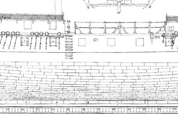
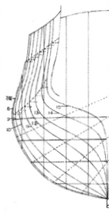
The cross section in Lavery & Hunt (which I will now refer to as L & H) clearly shows a wale or step line increasing the hull thickness at the gun deck level but a gradual variation in thickness below this point. So now lower wale line.
From the point of view of those out there more knowlegeable than I is this likely to be the case?
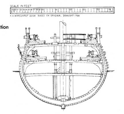
Hull cross section
(From L & H)
Cheers,
David.
- Elmer Cornish, egkb and canoe21
-
3
-
Thanks Mark,
Hopefully I won't have to change it again.
Cheers.
-
Looking at my log I just noticed that the title is now incorrect.
It should say 1:75, not 1:64.
Does anyone know how this can be changed?
Thanks and cheers,
David.
-
Change of plans.
I finally worked out how big the 1:64 model was going to end up, about 1,120mm (44") long with the main yard 350mm (14") wide. Too big!
Time for a scale rethink. At the scale of the Mamoli kit, 1:75, the model is 845mm (33") long. This is what I will build to.
Fortunately, up to now, all the work has been drawing manipulation and scaling so no serious backtracking, I can use much of the information I have prepared by just changing the last calculation from 1:64 to 1:75.
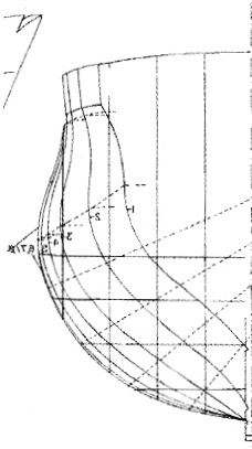
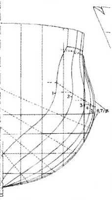
These are the hull cross section profiles that the bulkheads will be based on.


Bow

Stern
Cheers,
David.
(If it all falls in a heap I will always have the 1:75 Mamoli kit to fall back on!)
- aviaamator, MarisStella.hr, mtaylor and 3 others
-
6


HMS Surprise by Navis Factorem - FINISHED - 1:75
in - Build logs for subjects built 1751 - 1800
Posted
I have started on the fittings for the main deck, companion ladders, hold hatches, capstan etc.
I realised that I am going to have to complete all the details on this deck before I can fit the quarter deck, gangways and the forecastle. Of course this includes all the guns with their attendant tackle so this lower deck is going to have a lot of detail in place before I can fit and complete the upper deck sections.
Completing the top deck will involve lots of scraping etc of the final planking which I do not want to do in place in the hull as the process makes quite a mess and I do not want to be trying to clean out the completed main deck.
So I have decided to prefab the top deck sections complete with finished planking and drop them into place. Fortunately the top deck is in 2 separate pieces as it has a step from the gangways up to the quarterdeck. This step seems to be about 200mm high and I presume it is more symbolic than functional defining the limits of crew movement from "before the mast" to the officers area.
The deck beams have been shaped with the required camber to give the upper deck sections the required curve and the 2 sections slide into place, forward section first then the stern section slides towards the stern as it is wider than the top of the bulwarks due to the tumblehome of the hull.
The exposed deck beams in the waist are temporary as they are in the wrong place. They will be removed when the planking is complete and the final beams installed. From the L & H drawings these final beams are above the deck line and are located with brackets on the edge of the gangway.
Cheers,
David.
Upper false deck sections in place
Top side of removed sections
Underside
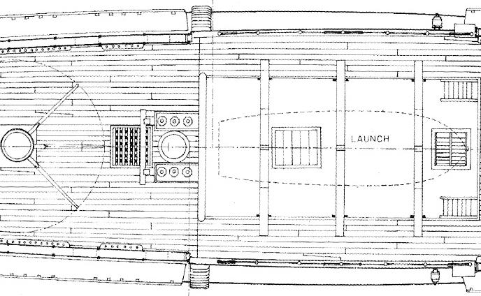
Long section through waist showing beam positions and support brackets (Lavery & Hunt)
The step up from the gangway to the quarterdeck can be seen here.