

AON
-
Posts
2,596 -
Joined
-
Last visited
Content Type
Profiles
Forums
Gallery
Events
Posts posted by AON
-
-
Thank you Druxey but they are already blackened with a marker and installed.
I had tried sanding any coating off the head and it didn't seem to help.
I'll try acetone tomorrow just for the heck of it.
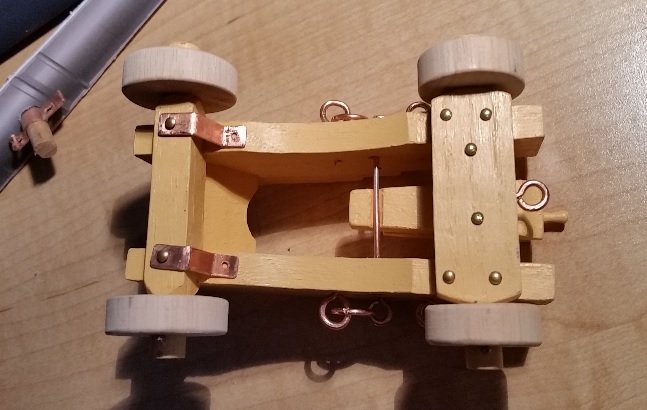
Presently trying to figure out how to drill and pin two of the four trucks so it is fixed to the mounting board and doesn't roll around when she heels over when handled.
- paulsutcliffe, druxey, Canute and 1 other
-
 4
4
-
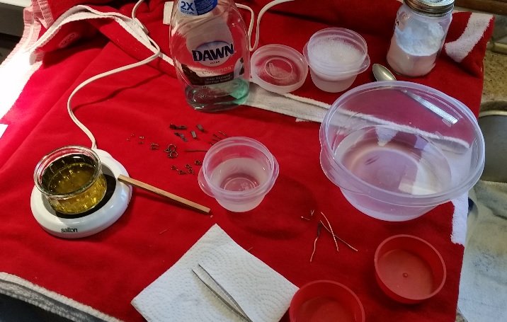
After all the hullaballoo (of my own making) over figuring out how to blacken properly... it turned out to be very easy.
I set up a work station, in the kitchen, on the counter, window to one side cracked open, stove overhead exhaust fan to the other side and turned on high.
One small container with cleaning solution (drop of soap and ammonia).
One small container with hot water and baking soda solution to stop the process.
One large container with clean hot water to rinse parts off in after treating.
One small container with hot water and a small amount of crushed rock liver of sulfur mixed with a wooden stir stick. Set this on my abandoned coffee mug warmer.
Pair of latex gloves and tweezers.
Cleaned, rinsed and dried the parts. Picked each part up with tweezers and swished (stired about in the solution while holding the part with the tweezers) them in the LOS solution for 5 seconds. Took it out and it was turning black. Did it again quickly... then once more and then into the baking soda solution... swished it about. Then into the clean rinse and done.
Repeated this for every part.
The copper blackened very quickly. The brass was a problem. I swished and waited and swished and waited and nothing. I let it sit for quite some time (20 minutes) and nothing. After 33 minutes they seemed to be dulling abit.... but it was wishful thinking. After 50 minutes I told myself to stop.
I am thinking they are calling these brass but possibly they are not... the packing reads: "solid brass". As you only see the head of these I have decided to blacken them with a black permanent marker.
-
-
The poplar sub-base was just stained with a Minwax Penetrating Stain #260 - Pickled Oak to bring out the grain but keep the clear unfinished look. It is presently drying. A clear sealing coat of Varnish will be applied afterwards. The MDF will be varnished only.
The sub-base will then be screwed to the underside of the mounting plate from below and felt pads will be added to protect table tops from any scratches.
Meanwhile I've done some more research into using lump or rock form Liver of Sulphur (LOS) that I had purchased and used once before about a year ago blackening the staples on the keel of my ship build. That attempt had flaked off but fortunately I liked the end result.
I'm guessing I possibly did three things wrong back then: too strong a mix of LOS to water, too cool a mix when the blackening process took place, and too long a soak in the mix.
The following PDF is a summary of the instructions I'll be following. I have also included a MSDS for LOS.
I will be doing some practise runs on copper wire and brass nails before I commit to blackening the pieces to be used.
This will happen tomorrow.
-
Well, I don't know you very well Druxy, but you seem very informative. I've noticed you've helped quite a few people on the forum (besides me).
On the other hand I know David Antscherl is a master at modelling and very knowledgeable (because he does the research) and I'd trust him in a heart beat... but he'd want me to research on my own first, so I have done just that before I see him this coming weekend.
Thank you again... BTW - I just explained to my wife how I wasted some money. YIKES
- mtaylor, Canute, paulsutcliffe and 1 other
-
4
-
and now this...
Funny how I couldn't find anything before.
So it is officially bolted with wooden plugs overtop.
Thank you Druxey for mentioning this.
This I will never ever forget.
- druxey, archjofo, paulsutcliffe and 3 others
-
6
-
and just found this in the forum with a slight change in my search criteria ( https://modelshipworld.com/index.php?/topic/14473-treenalingwish-i-hadnt-done-this/&tab=comments#comment-449644 )

- paulsutcliffe, mtaylor, Canute and 1 other
-
4
-
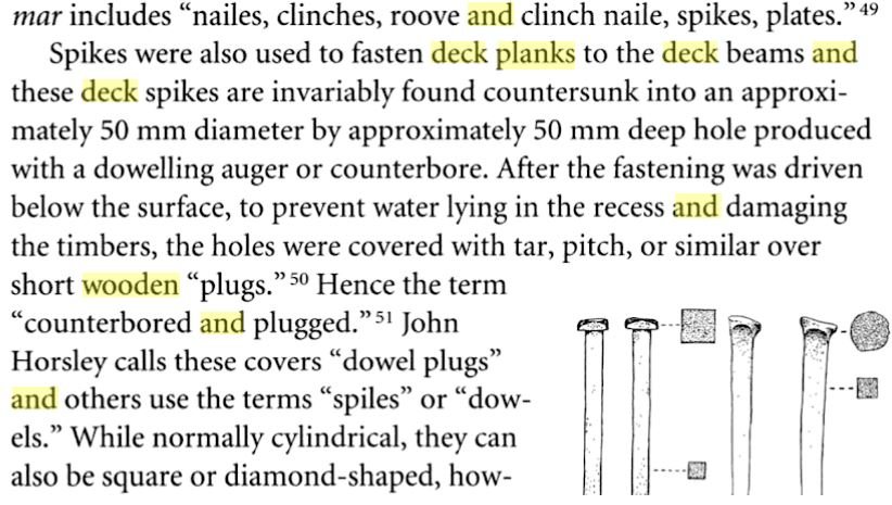
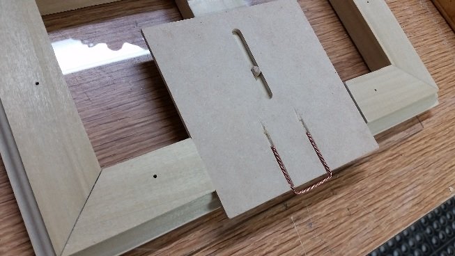
I've spent some time trying to find information of deck fastening.
In the Model Shipwright Magazine, issue 63 (dated March 1988) on page 53 is Part 9 of a good series of articles by David White entitled Traditional Wooden Shipbuilding. I think I will be allowed to post a screen shot snip of one paragraph (see below).
It substantiates in part what Druxey had stated earlier. David White does not mention plugs but plugs make sense.
I will continue to search.
- Canute, druxey, paulsutcliffe and 1 other
-
4
-
I could but it will likely look like heck.
They have a special sheer for metal nameplates to assure the edges are crisp and flat.
I could ask them to cut it for me.... but it was not the look I agonized over for a couple weeks.
I'll have to sleep on this, but thank you for the suggestion.
-
I have such a thing. Spring loaded barrel, fits in your palm...push with your palm.
It bought it years ago to insert finish nails into things like picture frames or paneling onto walls.
You have to be very careful with the amount of pressure.
Never thought to try it on pins for a model. Now I have to find it again.
-
-
-
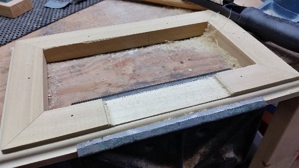
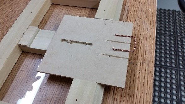
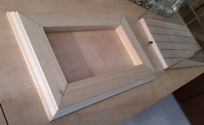
Then I started working on the sliding information tray. I made a support bridge piece between the frames, marked the depth, wood rasped and then sanded to the marks. Drilled and inserted the stopper dowel. I didn't get any photos of it until the final assembly.
Marked the location, depth and width on the front frame piece then I cut it down.
The sliding "tray" is a piece of MDF (medium density fiberboard) wide enough for the nameplate and deep enough to have a slotted hole to encapsulate the locking pin in a slotted hole. The pull out handle is made of three strands of 0.031" copper wire twisted together to look like rope. One end of the group of wires was clamped in the vise and the other end in the chuck of my variable speed drill. I ran the drill to twist the wires until I had the look I wanted. The wire was bent and the fiberboard was grooved for the wire to sit into, below the surface so the nameplate would sit flat (no bump). As an added precaution the ends of the wire were bent 90° downwards to fit into holes drilled at the end of each groove so when pulling on the wire it has additional holding power to the MDF. This was assembled and glued together. Then the tray was assembled to the sub-base and tested.

-
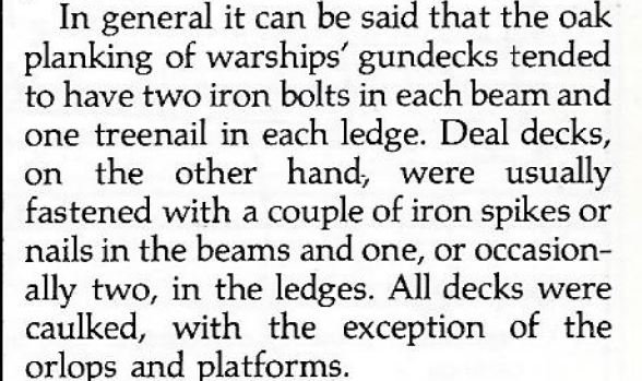
Had to go get my mitre saw from my son (he used it to build his garage) and cut the 45° mitres. Dry fitted them under the mounting board and case and made adjustments to get the "shelf" closer to the outer edge of the case. Then I sanded it down to the mark. Double checked and finally glued and clamped the pieces together.
- aviaamator, Canute, MEDDO and 4 others
-
7
-
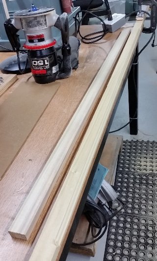
Worked on the sub-base frame. Practised routering on a piece of scrap to determine which profile was best out of three I had picked out. Decided on a 5/32" Roman Ogee profile. Took my length of 34" x 1-1/2" Poplar and with a 4 foot piece to ride on in behind it so the router didn't rock I cut the profile.

- Canute, paulsutcliffe, mtaylor and 2 others
-
5
-
-
I am afraid if it was my mistake he would not accept any fault (or off any discount to the price)
Ship Modeling from Stem to Stern by Milton Roth, pg 125 mention deck treenails.
Historic Ship Models by Wolfram zu Mondfeld, pg 98 mentions deck treenails.
He states "Please note: on iron framed ships - that is, after 1850 - no treenails or nails should be visable, but the wooden plugs covering the fixed bolts would be and would appear similar to treenails with a cross instead of an end grain."
TFFM Vol 3 by Greg Herbert, Pg 157 mentions deck treenails.
(funnily the other volumes of TFFM by David Antscherl does not mention treenails at all that I can find". I expect to see him on the 18th at our club meeting and will ask).
I confess to not know any more than I read.
Do you have a source of this info Druxey?
BTW - I did find an error... of my doing.
-
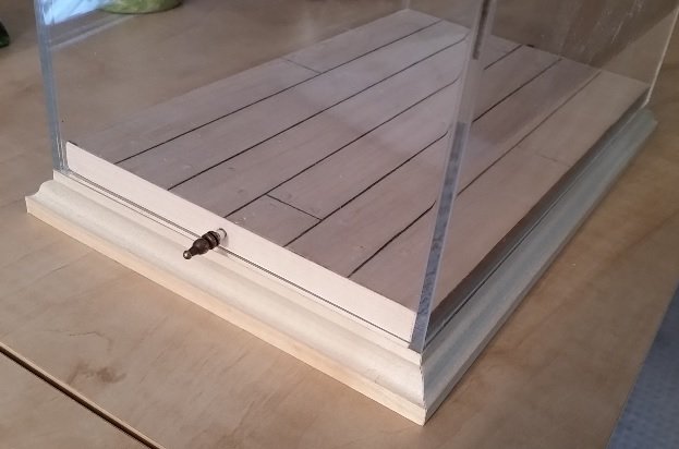
Sanded to two skewed short ends of the plywood mounting plate square and ironed on the maple edge trim. Using a #34 drill and my Dremel I carefully drilled a shallow pocket into the short end through the clear acrylic case. After removing the case I drilled the hole deeper for the pin.
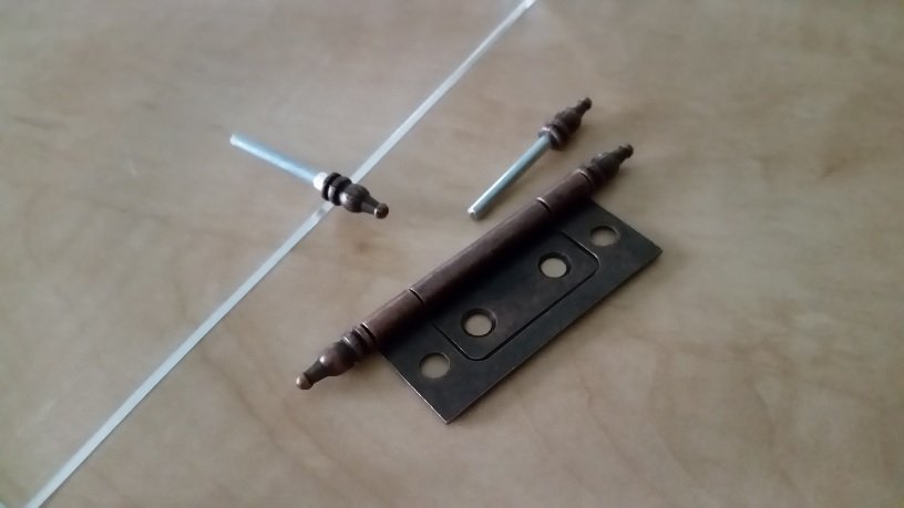
The pin was fitted to the hole and got stuck! As I pulled to remove it the ornamental cap popped off to reveal a perfect coned end. I decided this was the end I wanted exposed and the cap should go on the other end. It would not hold. I needed to press grooves (knurl like) onto the end to expand the diameter so it would grip and then tapped it on with my soft rubber mallet.
Cleaned out the hole a bit and it is now a nice snug fit.
Went to take the cap off the end of the other pin and found they used more glue on that one. Buggered the pin in my attempt to disassemble it. Thank goodness they sell hinges in pairs. I was able to get one of that pair apart and now have two good pins.
The case fits well and the pins hold it all together!
Tomorrow I hope to router some pieces for the sub-base and assemble it.

-
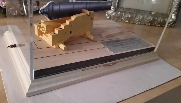
Picked up the nameplates today from our local trophy shop. Should have had them yesterday but they spelt NAVAL incorrectly (NAVEL). I could only laugh. They knocked $10 off the price so try as I might I couldn't find another mistake.
I decided to go with laser engraved aluminium. It is clean, scratch resistant, professional looking and easy to read.
I also decided to only mount the one on the deck as it looked to "busy" or cluttered. The other will be on a sliding pull out information tray or board just below the mounting plate and glass... yet one more thing learned at our last club meeting.
- Canute, paulsutcliffe, archjofo and 2 others
-
5
-
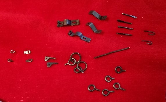
All metal pieces are made and need to be blackened.
The clear acrylic display case cover and my mounting plate were picked up today. The case looks wonderful but the fit is questionable. The case fits very well to the long sides but is too sloppy (too large a gap) on the short sides. This is likely my fault for not sanding the ends perfectly square to start with. The clearance measures 0.108" (2.7mm) whereas on the long sides it is 0.0005" (0.01mm). My solution is to sand both short ends square (as these are slightly out of square) and apply a 1/32" (0.8mm) maple wood veneer over the end to decrease the gap and snug up the fit with the acrylic cover. I should probably do the long sides also so the cut edges look finished.
Went out and bought a $4 pair of door hinges. Cut one in half and took the pin halves out. I will use these as the locking pins for the acrylic cover. This pin will keep the cover from popping off if the display case is picked up by the cover. Thank goodness I went to last months club meeting to learn this pinning trick.
- archjofo, mtaylor, paulsutcliffe and 2 others
-
5
-
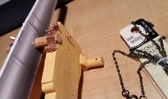
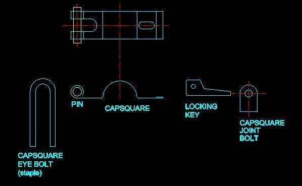
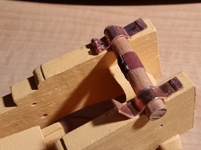
The CAPSQUARE JOINT BOLT was made out of plate, cut and filed to fit the slot in the Capsquare, and a hole drilled through to accommodate the Locking Key. The chain was purchased from Michael's, a local craft store in St. Catharines, Ontario (a 20 minute drive). It is from an 18" long black jewellery necklace collar. The Locking Key was made twice. I didn't like the first attempt and so, after sleeping on it, I made a more proper Locking Key. My copper plate material was too thin so I folded it over to get double the thickness, filed it to shape and drilled the hole to which the chain will attach.
- paulsutcliffe, Rainbow, mtaylor and 3 others
-
6
-
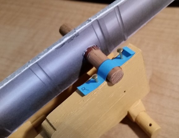
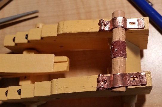
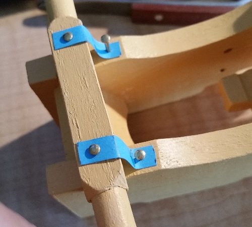
All these pieces were dry fitted to the carriage to give me a feel for the final look... and I like it so far. Two eye shafts needed adjustment so the eye sat properly. The simulated bolt heads are solid brass 1/2" x 18 gauge escutcheon pins bought at the local Canadian Tire store, hardware section. I cut the length short to about 1/8" and intend to glue these in place after blackening. I need to drill two new holes for the Fore Axletree Stays and the two missing holes for the Capsquare Locking Key Chain Rings.

- Canute, mtaylor and paulsutcliffe
-
3
-
The next item to make was the CAPSQUARE using yet another flattened out copper tube material and new paper templates. The plates required a number of attempts at bending. The slot at the hinged end was cut with my Dremel tool and cutoff disk, then opened with a drill bit to fit the CAPSQUARE EYEBOLT (a simple piece of wire with a bent U at one end to make a staple). The hinge pin was then roll/clamped in place. My second and third Capsquare turned into scrap and so there was a fourth before it was done.
Finally the Capsquare Joint Bolt slots were drilled and filed.
- mtaylor, archjofo, paulsutcliffe and 3 others
-
6
-
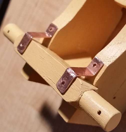
The FORE AXLETREE STAY was made of copper plate. The actual plate measures about 3/8" (9.5mm) thick or 0.04" (1mm) to scale. After hunting around my workshop I found some copper water tube that had a wall thickness of 0.032"... close enough! I needed to slice it open with a hacksaw, and flatten it out with a hammer on the anvil to make the plate. I started by making a paper template to fit on the model to determine the lengths required. Then cut it to size with a cut off disc on my Dremel tool, filed off the burrs, bent and drilled holes in the Stays.

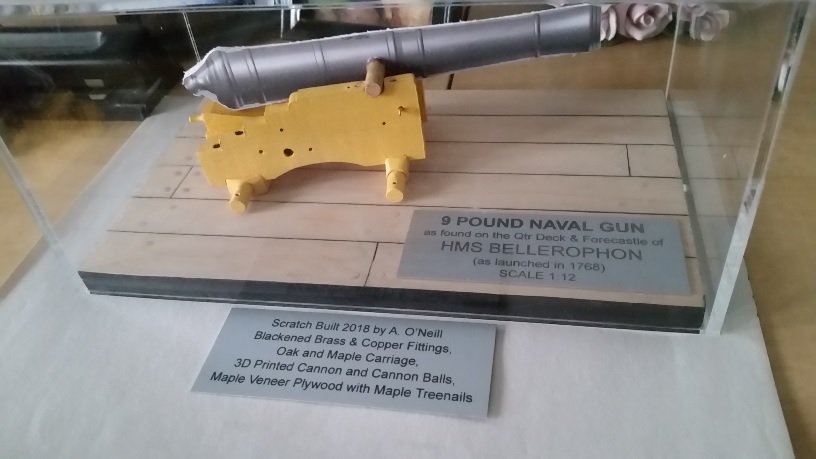
9 Pound Naval Cannon 1786 by AON - FINISHED - 1:12 scale
in - Build logs for subjects built 1751 - 1800
Posted
I tried acetone, scrubbed, washed, swished... nothing. Let it soak... nothing.
Me thinks Home Hardware "got some s'plain'n to do".