


AON
-
Posts
2,772 -
Joined
-
Last visited
Content Type
Profiles
Forums
Gallery
Events
Posts posted by AON
-
-
Thank you Mark
Let's see how it works...
The last couple of days have not been good for me and frames.
I did help my son pass some trim through the jointer
and I have wasted time waiting for gas fitters to connect the radiant heater in my son's garage while he was at work... have to go back tomorrow because the three different lists they made were still short parts.
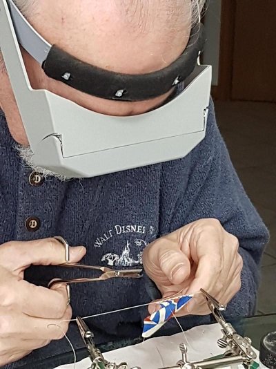
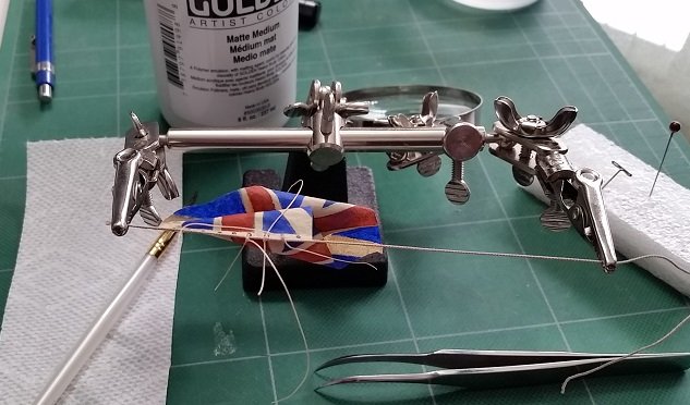
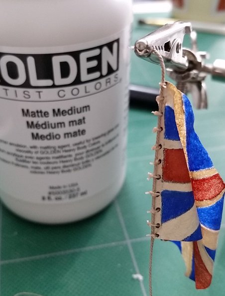
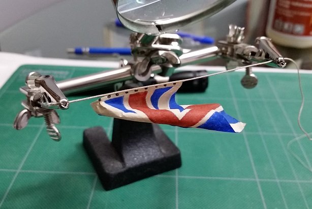
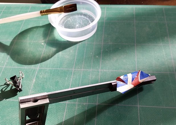
So I secured the jack to the halyard with the marline and sealed it with matte medium which applies white and dries clear. This will also add additional stiffness to the halyard at the hoist of the jack and provide addition adhesion to hold them together. I did not trim them too closely to the halyard purposefully as I want them to be noticed.
Possibly I will find time to make a tiny cleat tomorrow.
Thank you again Mark!
That was easier.
- GrandpaPhil, mtaylor, paulsutcliffe and 2 others
-
 5
5
-
-
It is Thursday morning and I find the imperfection of my flag is growing on me. It seems to make it more realistic and worn.
Yesterday I employed a set of extra hands, found some 1 inch line in my stash and glued the flag to it. I dabbed a fine line of yellow glue to the line and while pre-aligned and supported on a chuck of 2x4 wood I manoeuvred the two together.
The head of the hoist edge did not contact the line. After allowed to dry, I moistened the corner with a soft paint brush and water and reshaped it to align with the halyard. Presently it is drying. Once done I will glue this to the line.
I managed to drill two fine holes into the truck or cap of the jack staff for the line. As I was concerned with breaking the truck I started with a #76 drill bit in my pin vise and while slowly twisting it back and forth to drill and clear away the chips I sequentially opened it up with slightly larger bits until I reached #70. This will allow me to stuff the line into the hole after I dab some glue on it.
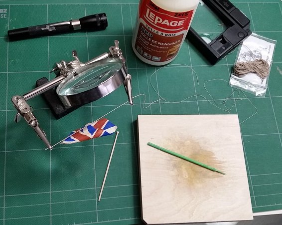
I found rope for the marline and still need to make a cleat.
And I still intend to print a flag to see how it compares.
(and once again my photos are loaded out of intended order but I've managed to drag them intoa proper sequence))
-
-
Practically done with this attempt. I am not completely satisfied with my painting and may make another after I purchase some green acrylic paint and a softer white. I would use a finer brush and thinner wash (acrylic paint diluted with water) on any other attempt. I will try the "printed" version on tissue paper for comparison but I feel I will need to add the hoist edge and grommet holes to the image so these are printed also. I'll need to acquire white tissue paper at the dollar store and the fixative from Home Hardware to pull this off.
My reference for the grommet holes is Volume IV of TFFM (The Fully Framed Model) pages 121/122, and is clearly shown in the bottom photo on page 203. His reference is Steel - Rigging and Seamanship, Volume II, page 129 (`the jack is bent to the halliard by rope bands of 2 lb of white marline`). 2 lbs is the weight per fathom (6 feet = 1.8 meters) so I imagine this to be something like 1/2" diameter rope.
So I did the minor touch ups, marked off 9 inch intervals (equally spaced from top edge to bottom edge) against the hoist edge and added dots to suggest the sailmaker's style sewn grommets (http://www.frayedknotarts.com/sailmaking.html) for the 2 strand marline rope (https://rwrope.com/classic-boat-supplies/tarred-marline-tarred-hemp-twine/) used to secure the hoist edge against the halyard (not the staff as I typed earlier) as the jack was raised with the halyard. These dots were made on both sides using the smallest paper embossing ball burnishing tool (0.03" or 0.81mm diameter ball) that I have in my arsenal.
I intend to simulate tying my flag to the haliyard with glued thread so once the simulated grommets dried I made a hole through each using a #74 drill bit (0.0225" or 0.5715mm diameter) which would be about 1-1/2" diameter at 1:64 scale. This is likely too large but I will hopefully be able to coax short lengths of simulated marline through those.
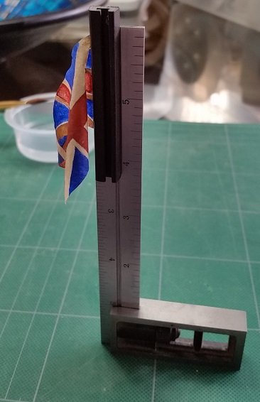
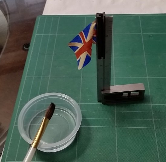
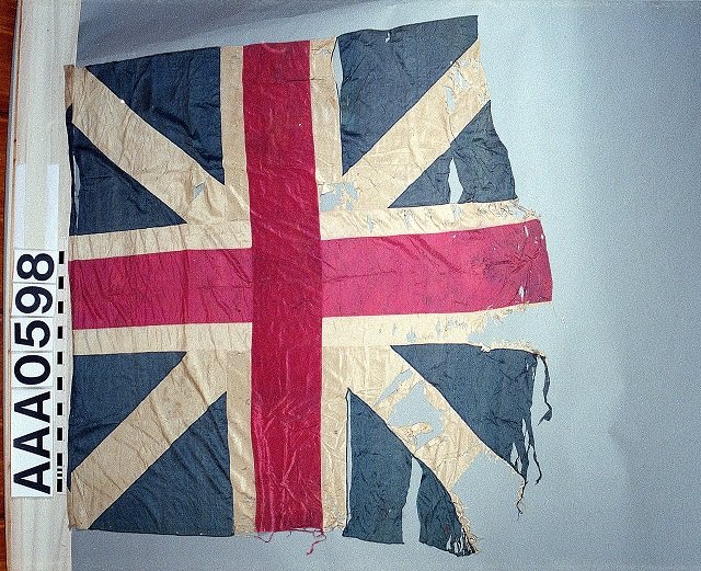
I put the plug back in and cut out the jack using a scalpel. I then clamped the hoist edge to a metal square with a magnet, brushed some water onto the flag and put in a primary or initial curl. After allowing this to dry I then wetted the outer portion or the fly quarter and put in a secondary or final curl. I had to set the square on end to allow the Silkspan to retain the shape while it dries.
So below are four photos and a short video showing the finished product.
Finished product - Union Jack video.wlmp
-
Grommet dots along the hoist side at about 9 inch intervals for loops that held the hoist against the staff.
Yes there were toggles (now Inglefield clips) at the top and bottom of the hoist.
I would be very interested in seeing images of the captured flags... particularly in this case a Jack
-
-
-
Dowmer
Thank you for the links. It seems simply enough although I am not familiar with the spray... worth Googling.
Just had a review and they both look wonderful.
However I just had a look at my flag and she seems much better now that she is thoroughly dried. I simply need to touch up two tiny spots.
Held it up to the light and the flag is translucent (can see through it) except for the hoist edge which was the effect I was after.
I will also need to add the grommet dots and drill holes through so it can be fixed to the staff.
Then it needs to be shaped.
Hope to post these later today.
Druxey: As this is day four after my eye needle I am now allowed back in my workshop so I'll be getting back to my forward cant frames. Slow and steady....
-
-
So it started off looking like crap but finished not so awful.
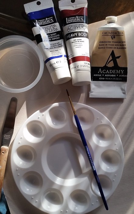
Got all my gear out.
A Number 2 brush seemed narrow enough.
Mixed the Cobalt Blue Hue with tiny touch of Naples Yellow Hue to mute the blue.
Thinned out the Red Oxide with water alone and applied light coats. Possibly I should have added a touch of green to mute the red but I thought it looked okay.... and I didn't have any green!
Used water thinned Unbleached Titanium White in between.
All blue and red hues of paint was thinned with water and applied as a wash so as not to be opaque.
The white was applied similarly, but less so on the hoist edge so this edge would be opaque.
Both sides of the material were painted, allowing one colour to dry before switching to another.
I had the red and blue colours bleed into the white area before the white was applied..
At first I found the mounting board was so thin that when the Silkspan got too wet it sagged and touched the paper below that was on my table top and started the bleeding... but then it happened when I set it on top of a plywood board I had used in the sail-making workshop.
Possibly my hand wasn't steady enough... or I can blame it on my bad eye

After applying the titanium white wash the blue and red bleeding seemed to disappear.
I'll have another look in the morning and do some touch ups... wait a bit and then decide if I'll call this the trial run and take another stab at it or decide that this is a keeper.
-
The following post is with permission from Admiralty Models, specifically David Antscherl. This technique was learnt at both the Admiralty Model Sail-making and the Flag Making Workshops I had attended years past. They are also presented in David's Books: The Fully Framed Model, Volume IV (referred to as TFFM) and in The Greenwich Hospital Barge.
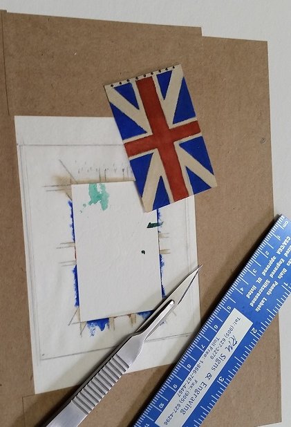
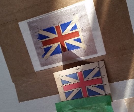
I must explain that although I had decided to go with the 1:2 ratio for the size of my flag, after printing it and the 2:3 ratio version, and having noted that the actual flag I found online at the NMM, RMG website was more square than rectangular, I've changed my mind and decided to go with the more box looking version.
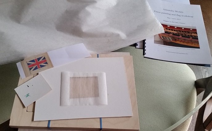
First you need a mounting board. My mounting board is made from stiff illustration board and has a rectangular hole cut out of it. The plug from the hole is saved and reinserted when tracing the image to the cloth. It is light and easily handled.
Second you need brown gummed tape, the type used by artist. It looks like butchers tape to me. I purchased mine online through DeSerres of Longeuil, Quebec. They refer to it as "gummed brown paper". The tape is cut into four lengths to hold the Silkspan down to the mounting board. You dampen a sponge and wipe the gummed side lightly and it is ready to use.
I cut my Silkspan oversized, larger than the mounting board hole. Silkspan is the cloth used by airplane modellers and looks like the material used for tea bags. I dampened it with water and let the excess drain away. Then I placed it on the mounting board over the hole while the cloth was still wet. Note that the plug was removed from the mounting board! I did my very best to lay it flat but had to ask for help with an extra set of hands to get the job done. The damp Silkspan was taped to the mounting board with the brown gummed tape. This was put aside and allowed to dry. As the cloth dried it stretched tight... no wrinkles.
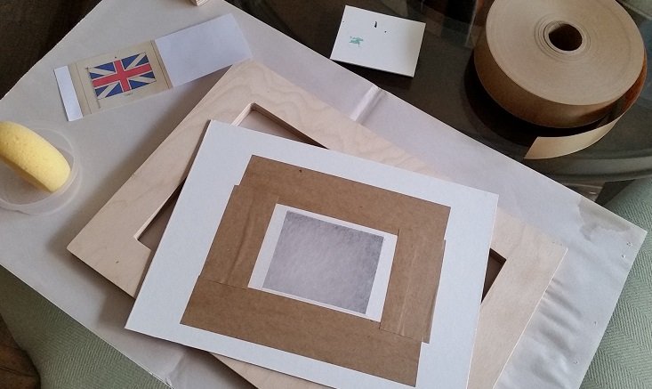
Once dry I re-installed the plug in the mounting board, then I traced the image of the flag onto the Silkspan using carbon paper, a sharp soft pencil and a short straight edge. I did not use too much pressure as the cloth, to me, is quite delicate (thin and open weave). The image was taped to the board with green painter's tape so it would not shift.
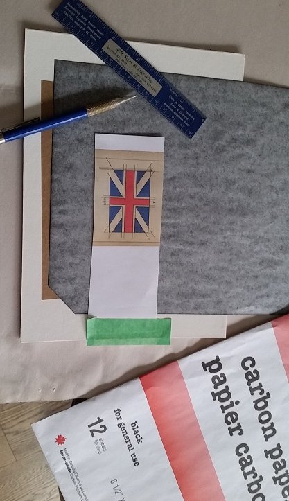
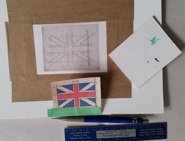
With that job done now comes the fun part.... this involves mixing muted blue and red colours which will be applied (with a steady hand and fine brush) as a wash (thin
- Dowmer, GrandpaPhil, mtaylor and 5 others
-
8
-
here it is at 2:3 ratio (7'-6" x 11'-3")
- mtaylor, Canute and GrandpaPhil
-
3
-
Funny enough, after reducing them 74% they scale 7-6" x 15'-0"
I could easily re-scale in one direction (horizontally) to match The 2:3 ratio of TFFM versus the 1:2 ratio of The Anatomy of Nelson's Ships using MS Paint program.
Found all my supplies from my Admiralty Models Sail-making Workshop (2014) and Flag workshop (2015), Plus the suppliment in TFFM Vol IV.
Time to do some reading.
-
not an issue.
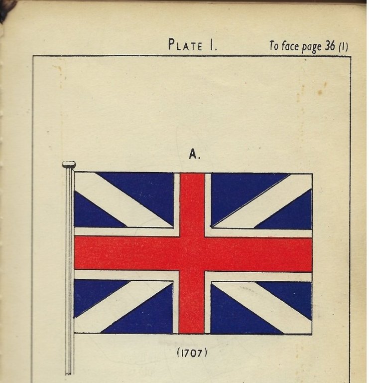
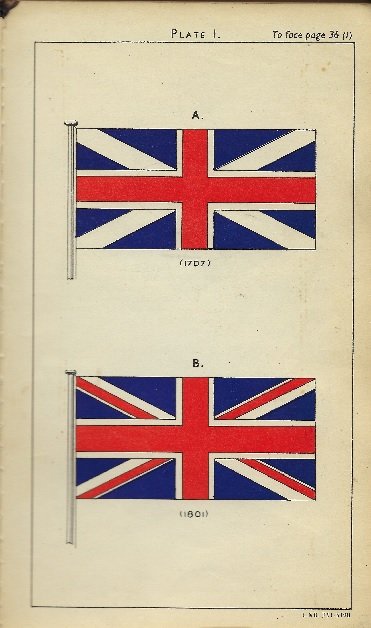
found a decent image of the union flag in my dad's Manual of Seamanship 1937 Vol. 1 book (Plate 1)
next I've got to dig out my stash of silkspan cloth
- cog, Canute, GrandpaPhil and 1 other
-
4
-
-
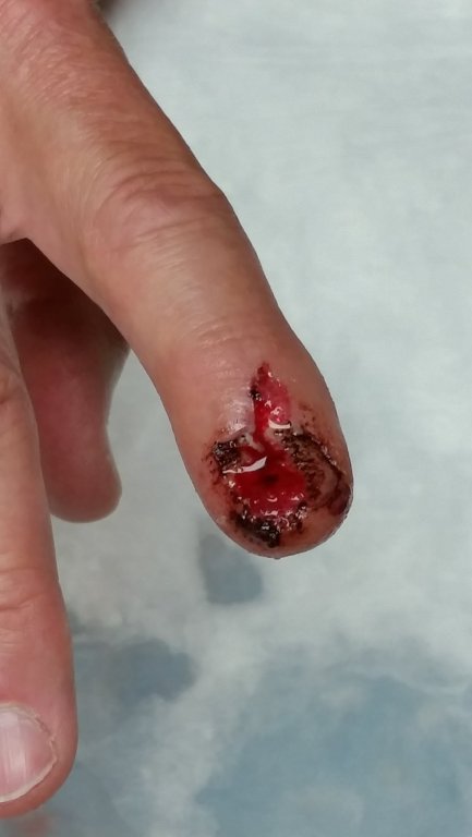
A hot shower helps my thinking... working out problems. But I'd likely just drown if I opened my mouth. And power tools. OMG. I'm dangerous enough without adding water into the mix.
Here is proof.
All healed. Fingernail grew back. And I work much smarter now.
- Canute, FrankWouts and popash42
-
1
-
 2
2
-
I took my second bowsprit (scrap) and turned it down as small as I dare. Then I used course sand paper wrapped partially around from behind so it also acted as a support and worked it lightly back and forth until that section was within dimension. Then I moved over to the next section and eventually finished off with finer sand paper.
All this while I sang along to the tunes coming from the radio on the shelf just above.... it helped pass the time and it took a considerable amount of it. But my singing still needs considerable work.
😆😎
- paulsutcliffe, mtaylor, cog and 3 others
-
6
-
Thank you very much Lawrence for the kind words.
There is a long story explaining my workshop and tools. One envolves a career mentor. It took as long as the telling of the story to aquire them both.
I am presently recuperating from yesterdays needle in my eye. Pain killers and ice allow me to see your post. 8 am this morning was a whole other story. 8 pm last night was hell. As I cannot work in my shop for the next few days I think I might make my Union Jack tomorrow or Monday.
Wish me luck painting.
-
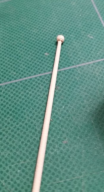
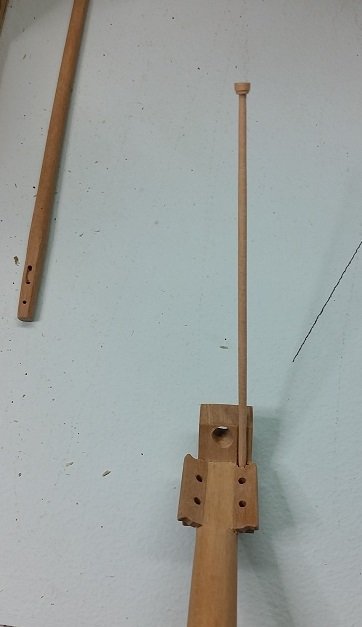
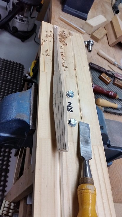
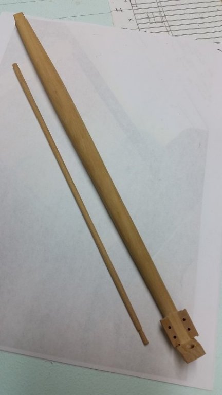
While I am still working on the forward cant frames I went ahead and made the Jack Staff for the Bowsprit Cap.
Full disclosure... I had to make it three times.
From Steels Rigging Tables I find the Jack Staff of the 74 Gun ship was 4-1/2" diameter x 18 feet tall.
From The Anatomy of Nelsons Ship's I find they were tapered (smaller at the top) with a Cap or Truck.
Visiting one of our club members on Wednesday I discovered the cap or truck had two small sheaves in it, one to port and one to starboard, one was a spare. The halyard had to be secured somehow so he figures they must have been something like a cleat near the bottom facing aft.
Looking at TFFM Vol IV I see the cleat on the Jack Shaft.
So My Jack Shaft is 4-1/2" diameter (0.07 inch) at the base or heel and 3-1/2" diameter (0.05 inch) at the head or top with an 7-1/2" diameter (0.12 inch) cap or truck. I used 1/8" diameter dowelling, secured it in my drill press chuck and carefully sanded it down to the tapered shape.
When I had the shaft shaped proper I used a tiny saw blade to shape the truck to blend into it.
I will not be cutting in the tiny sheaves as they are just too small.
I have yet to make the cleat.
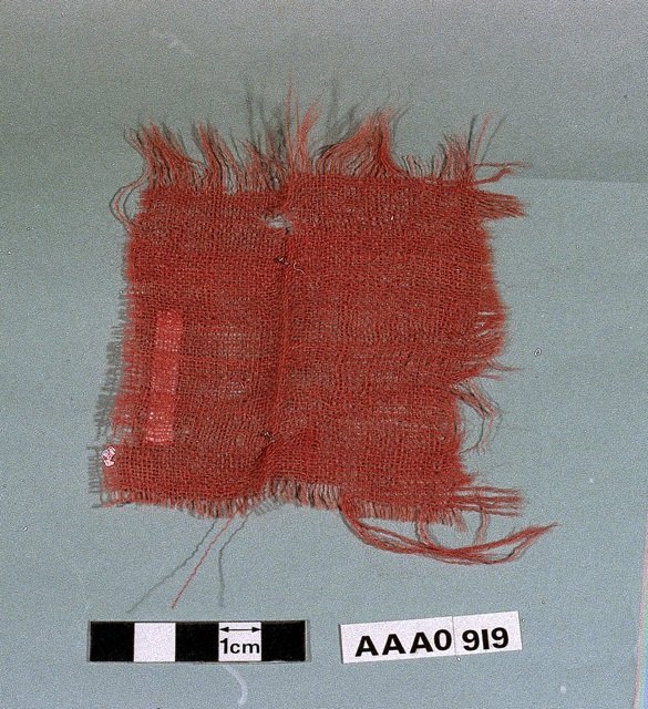
The Flag (the jack or small version of the full size flag) will be 7'-6" hoist x 15'-0" fly as The Anatomy of Nelson's ships described them as 10 breadths (or 9 inches x 10 = 90 inches or 7'-6") and the size was a ratio 1:2. The Fully Framed Model, Vol IV reads they were sometimes 2:3 or 11:18 with one surviving Jack from Trafalgar measuring 7'-4" x 11'-7". As mine is dated prior to 1801 (when they added Ireland to the Union) there will be one saltire missing from what we recognize today.
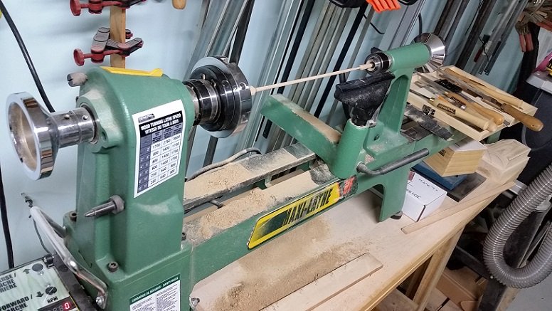
Following are pics of my Jack Staff, a union Flag dated prior to 1801 and a scrap from Bellerophon's ensign at Trafalgar. The last shows closeup the open weave of the material. Also one very short video of how I shaped the staff.
I am going to make the Union Jack for this staff next.
- paulsutcliffe, dvm27, druxey and 6 others
-
9
-
-
-
Final updates.
My third bowsprit and first jib boom.
-
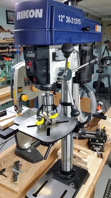
Last weekend I went to Lee Valley Tools to pick up some clamps for the dust collection hoses. They had this drill press that caught my eye.
I went over and grabbed the chuck and gave it a wiggle. The damn thing didn't move! After talking to the floor guy I brought it home.
See my cheap Canadian Tire drill press wandered all over the place. The store clerk at Art's Tools (where I normally shop) told me you cannot get a decent drill press that doesn't wander anymore for a reasonable price. Only industrial grade ($$$$) have that.
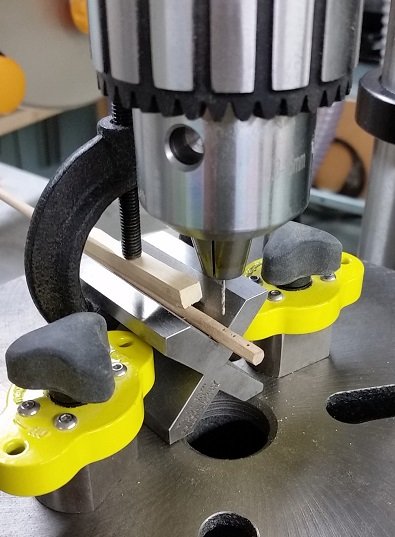
Well my new drill press does it. As a bonus it handles small number drills. The chuck sizes reads 0.8 to 16 mm (0.03 to 0.63 inch). Well I have had a #76 drill bit (0.02 inch or 0.53 mm) in it and no wiggle!
Below is the heel of my Jib boom being drilled.


HMS Bellerophon 1786 by AON – scale 1:64 – 74-gun 3rd Rate Man of War - Arrogant-Class
in - Build logs for subjects built 1751 - 1800
Posted · Edited by AON
Had to hunt for some dimensions for the cleat and found information in my copy of Historic Ship Models by Wolfham zu Modfeld (pgs 246-247).
Clamped a piece at thickness and started shaping it upside down as my first attempt right side up didn't survive.
My dimensions are A = 0.215" (0.64 mm) long ; B = 0.1095" (2.78 mm) Tall (peg not included); C= 0.065" (1.65 mm) Thick or wide. The height will yet be reduced to be nearer what it should be.
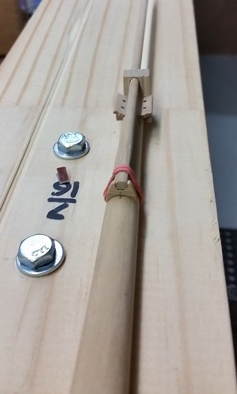
Marked off (to be above the bowsprit cap and below the bottom of the hoist edge of the jack) and drilled out the jack staff to receive the peg and glued the two together assuring it was oriented correctly with the halyard holes above.
Letting it dry now before I attempt to cleanup the shape a bit with very fine sand paper while wearing my magnifying goggles.
Then I will assemble the flag and halyard to the staff and cleat.