Thistle17
-
Posts
1,042 -
Joined
-
Last visited
Content Type
Profiles
Forums
Gallery
Events
Everything posted by Thistle17
-
 After seeing Chuck's work me thinks I should take up knitting or some such past time! Just kidding I guess I will muddle on. Joe
- 1,784 replies
-
- 8
-

-

-
- winchelsea
- Syren Ship Model Company
- (and 1 more)
-
NAIAD 1797 by Bitao - 1:60
Thistle17 replied to Bitao's topic in - Build logs for subjects built 1751 - 1800
Master works bitao! Your joinery is superb. You missed your calling as you should have been a master shipwright. Maybe in your next life???? Joe -
NAIAD 1797 by Bitao - 1:60
Thistle17 replied to Bitao's topic in - Build logs for subjects built 1751 - 1800
An imaginative variation of the machinist 'V" block where the hold down always seems to be in the way. Great design of the clamps. It seems easily transferable to a wooden version for those not into machining non ferrous material. Joe -
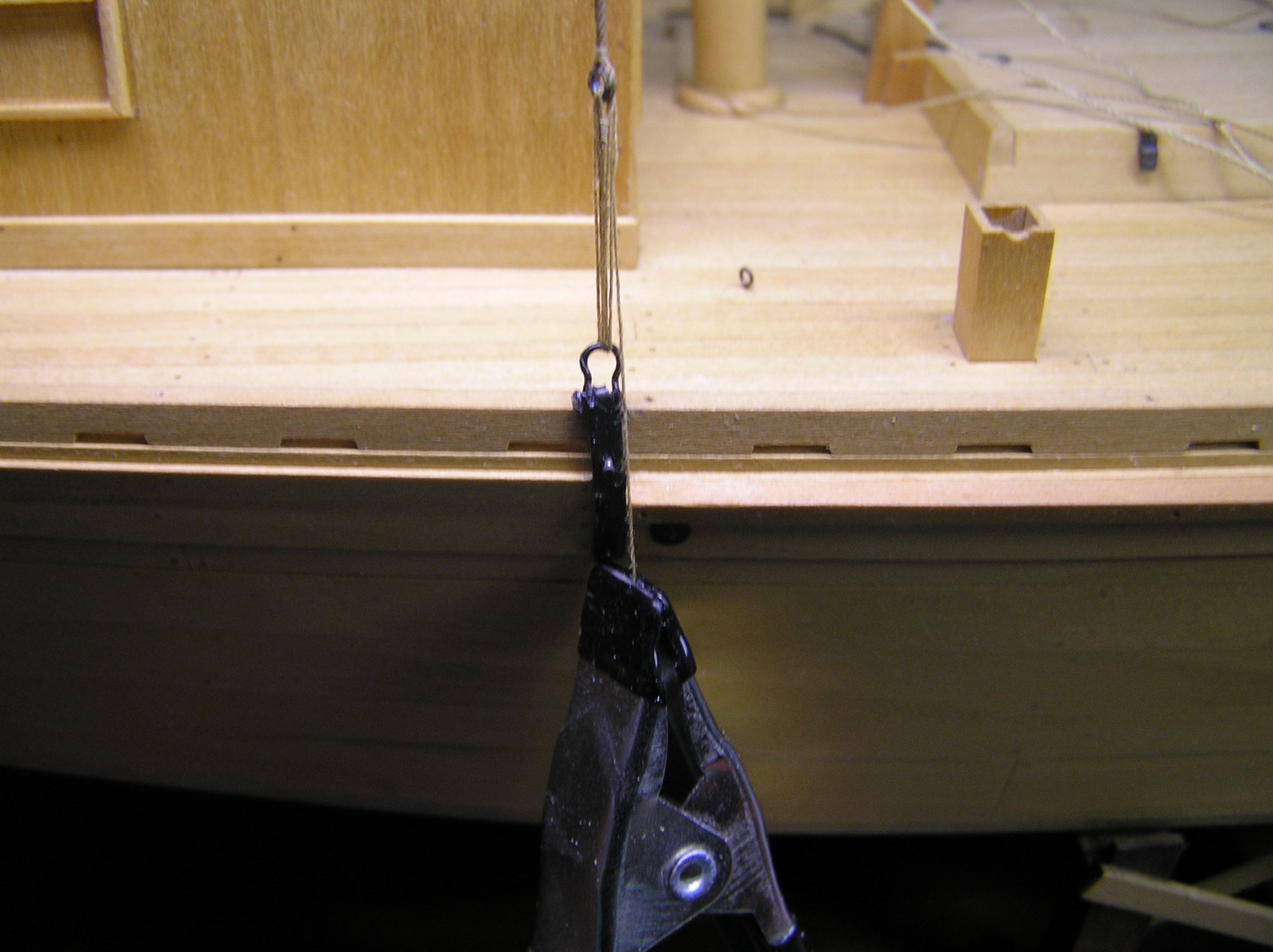
One could have a healthy discussion about the precepts of restoration. When is a replacement part, made anew, but differently, yet retaining the functionaly to be considered an unfaithful reproduction. Well call it what you wish. I had to scrap the replacement chainplates. During install they were so delicate that the tip which was a piece of soldered tubing attached to the plate body separated in both accounts. The stress was just too great on this diminuitive part (just about 1mm). I had to remake them much as I and others made Cheerful chainplates. You can find this in Chapter 9 of the Cheerful build log. Basically the chain plate has a tang at its top that is bent into a loop that allows connection of the lower deadeye to the chain plate. In this model there are no deadeyes. There is a looped line that passes through a shackle attached to the formed eye of the bent over tang on the chain plate and the shroud eye to adjust tension. Attached photo is the reconstructed chain plate with shroud lashing installed but not tied off. Tie off is identical to deadeyes. It is no wonder why they were missing on the model when I got it. I will move on from here and not look back. Joe

-
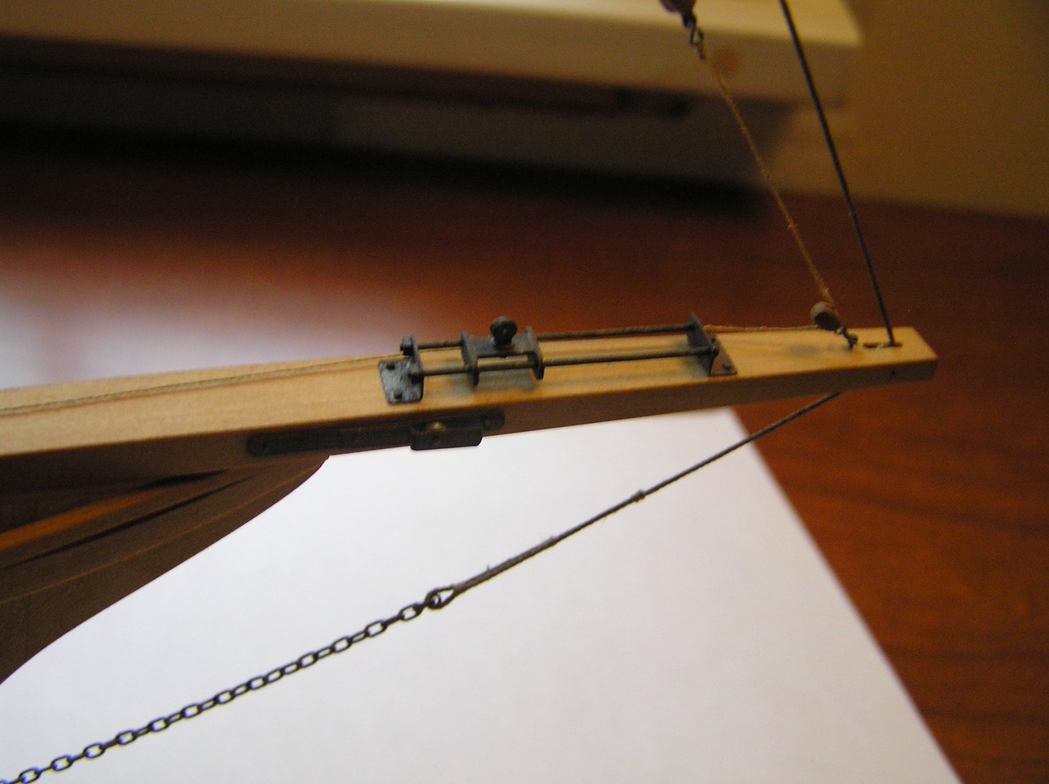
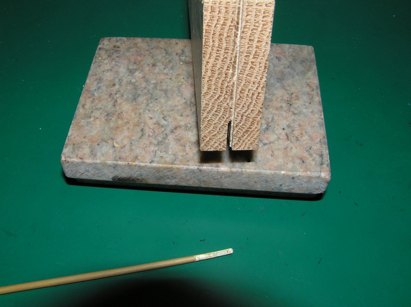
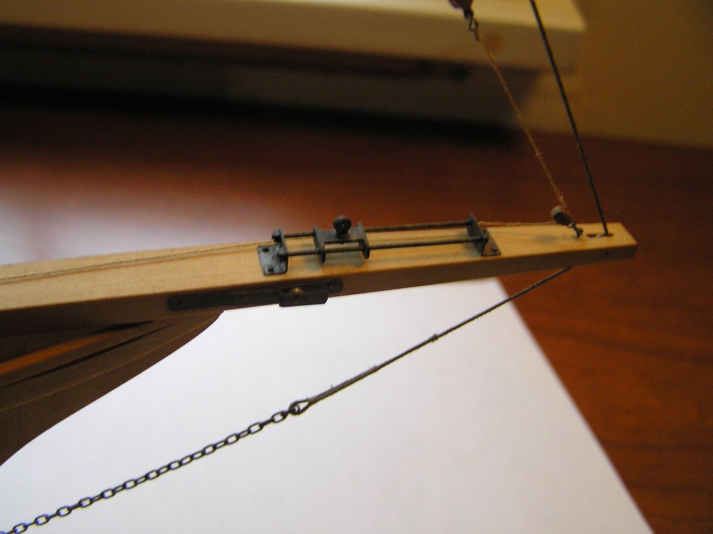
Preparations to repair the rigging have gone a bit slower than anticipated. I finally gave up trying to repair the broken brass chain plates that were on the model. Curiously the builder had decided to make them in 3 parts; a lower section connected to the hull, a mid section that was bent and soldered to sit vertical and the schackle like shroud tether. Between alignment problems and poor solder joints (even after cleaning and tinning they would not hold) I gave up and started anew. The remade versions were one piece straps of 3/32 X 1/32 brass strip bent to the correct angle. The chain plates were fashioned with a narrow tang at the top similar to Cheerful's chain plates. I must be losing it here is an [EDIT]I am working on 2 models at once, Cheerful and the Sharpie. The Sharpie chain plates were made differently on the original model. A brass strip was made of the dimensions stated and tapered a bit at the top. Atop the narrow end a small brass tubing of 1mm was soldered. To this new pre-formed shackles were attached. They were made this way to faithfully reproduce the original modelers intent. They are much harder to make however.These only need blackening to complete the process. Now the club foot boom termination on the "car" or traveler for the jib was a different story. The model as received was missing the metal work and until I received help from Reuel Parker's article in Professional Boat Builder I was at a loss to come up with a design. In the PDF above, on page 54, figure 3, is what I needed to recreate the element. I tried twice to make the forward metal work but each time the results were either only partial fufilment or were unacceptable product. On the third try I decided to try a different approach. Starting with some 2mm square brass tubing cut to length to include the forward yoke to attach to the car and long enough to simulate the boom strapping. The yoke holes were then drilled. From earlier experience I knew any files I had were too thick to fashion the yoke ears by removing the top and bottom walls of the tubing so I turned to my Byrnes saw knowing the 0.030 slitting blade could cut through the brass. Holding the piece safely was the problem. Shown in the photo below I cut a narrow slit in a piece of hardwood, trial fitting as I went and flipping the face against the fence for an exact centerline cut. I stopped when I had a strong press fit of the 2mm brass tubing within the slit. It then became a simple matter of moving the fence gradually and subsequently flipping the craddle face against the fence to cut the desired openings. A small section of the piece was left solid on all faces to maintain structural continuity. In turn the boom was shaved slightly to accomadate the newly formed simulated straps. The product is shown below the holding block. What remains is the "in haul" metal work to complete the final missing rigging elements. I don't want to admit to the number of hours it took to get to this point. Joe
-
Just my two cents here. I tried to improve production on Cheerful by ganging them (4 at atime). Not a good idea as the char and bevel make it difficult to get it done to satisfaction. Removing the char well and getting consistent diameters was the challenge. Rusty you are back at it with a vengence. Wonderful work. Would like to have you featured in January or february if not in person with some of the photos that cover technique. lets talk. Joe
- 642 replies
-
- 3
-
-
- winchelsea
- Syren Ship Model Company
- (and 1 more)
-
David the Zoom coverage of your model was so lacking (not anyone's fault, just the nature of remote viewing) at the HRSMS that it did not do your model justice. In terms of fittings, the Florida Sharpie has minimal fittings as i suspect the real craft did, given they were built in "back yards". My sharpie has 4 open chocks at the bow/stern for mooring, two bowsprit cheek mounted blocks for anchor operation and nothing else. The tack rigging is all deck mounted blocks. The rudder is in an aft wheelhouse so not much external there to speak of. Cleats are all located on the main cabin as the helm controlling all but the jib. If that helps. Joe
-
I will give your suggestion a try Ron. Thanks. Joe
-
This discussion of a new and more ambitious project seems to be creating quite a stir. Surely there is need for a vaccine or pill to slow what appears to be another spread of unbounded enthusiam or a closet of unfinshed models! Present company included. We are all hopeless!!!! Joe
- 1,784 replies
-
- 5
-
-
- winchelsea
- Syren Ship Model Company
- (and 1 more)
-
Another example of running a full sytem check of function before the product goes out the door. You just solved why my system overode my DIY limit switches. Thank you Ron. Joe
-
I ran into a set of mechanical and software problems with my 3018 Pro. Not sure this isn't normal for everyone. For a seemingly well made, reasonablly priced unit it does make one wonder how much testing these products have had prior to the mnarketplace. Nonetheless Ron your journey is packed with good information and should be helpful to those that follow. Thank you for posting. Joe
-
The kind and supportive editor at Professional Boat Builer sent me a reprint of the Parker article in the June/July issue of 2021 that fully describes the bowsprit rigging and rationale for club foot booms and "cars" or travelers. It even gives more detail on page 54 of just how this area of the boom should be rigged. I have already made the "business end" of the club foot boom but am now considering a 3rd redo to more accurately reflect this new data. The editor of Professional Boat Builder has graciously granted permission to include Reuel Parker's comprehensive article. There is a wealth of information within. As I reflect on my pursuit of the sharpie history and its characteristics my respect for this vessel continuses to grow. I also have to acknowledge the people who build, restore, preserve and document the real craft.. Without them this information may forever be lost. Joe Bowsprits191-FINAL.pdf
-
I see reference to starting Chapter 10 in Chuck's build. Is Chapter 9 the stove build or do we await it's release? Joe
-
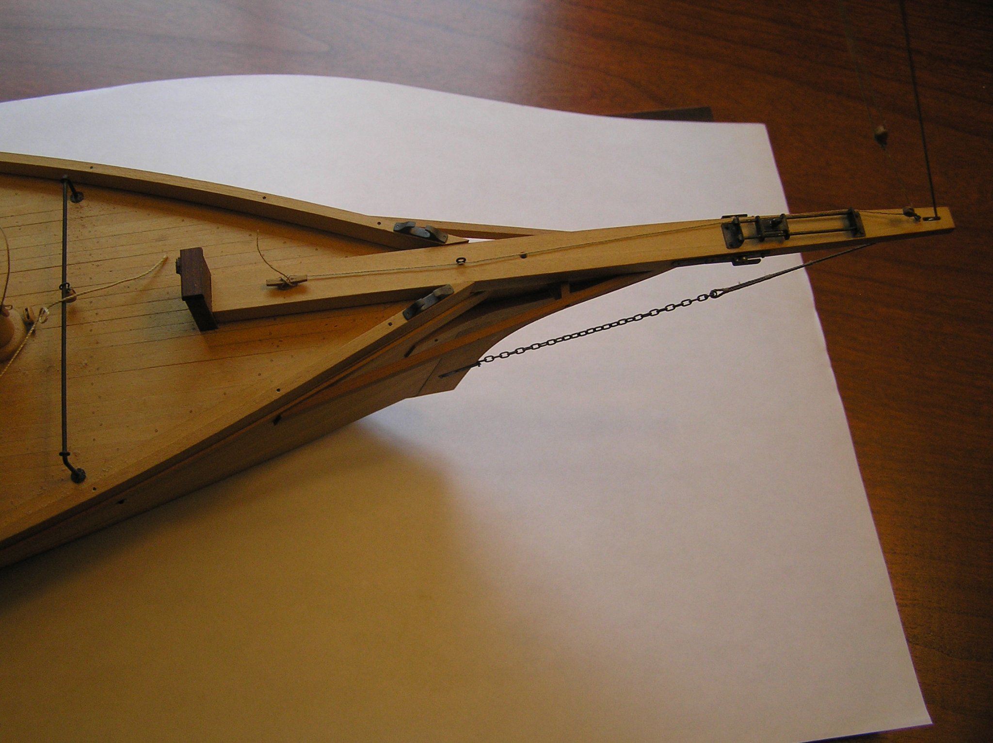
With Roger's added reference of the book, The Sharpie Book, by Reuel Parker, I now have a much better understanding of the rigging of this vessel. I repeat the quote from an email I received from Reuel Parker here about the bow sprit rigging which was most puzzling to me until his revelations: [The forestay rove through a sheave in the bowsprit is a typical Chesapeake Bay arrangement, but there is usually an outer forestay with conventional bobstay beyond the inner forestay, whose function is to support the mast and carry a “spectacle iron” from which lazy jacks are suspended to contain the club foot boom and furled jib. This is absent here, so there is only the single forestay. The “car” on top of the bowsprit allows tensioning and releasing the club foot jib boom, which is absent in the photo. The car arrangement was commonly used on schooners. The inhaul lanyard is missing, but the outhaul lanyard is in place. There is a gooseneck on top of the car for the missing boom. The traveler on deck is for the jib sheet, which would be attached to the aft end of the club foot jib boom; the block at the front of the mast is for a fairlead for the jib sheet. The cheek blocks on each side of the bowsprit are anchor rollers. You might refer to Chapelle’s “American Small Sailing Craft” and his booklet on Skipjacks for further information. Or my article in Professional Boatbuilder Magazine last summer on Bowsprits.] In his book he also describes on pages 143 and 144 the "car" or traveler arrangement for a San Juan 36 foot Sharpie. the only difference here is that the club or boom is 'fairlead back to the cockpit coaming for control by the helm. This would be difficult on the Florida Sharpie as the deck would have been laden with catch making the fairlead difficult to control I suspect. So the picture has indeed opened up. As I suspected the cheek blocks have nothing to do with the "car" or traveler. So that is no longer a point of confusion. Further I have to consider his advice on the fore stay comments and the missing irons. I have contacted Wooden Boat to get a reprint of the article he suggests and should be getting that soon.
-
Florida Sharpie Fore Stay Sail Rigging
Thistle17 replied to Thistle17's topic in Masting, rigging and sails
Well Roger the "bread crumb" trail has opened up a bit. After I received Parker's book I rapidly read sections that might pertain to the information I was wanting. The detail was not there but the next best thing was; a way to contact Reuel Parker! Amazingly he responded yesterday and provided me the following information. I quote his response: [The forestay rove through a sheave in the bowsprit is a typical Chesapeake Bay arrangement, but there is usually an outer forestay with conventional bobstay beyond the inner forestay, whose function is to support the mast and carry a “spectacle iron” from which lazy jacks are suspended to contain the club foot boom and furled jib. This is absent here, so there is only the single forestay. The “car” on top of the bowsprit allows tensioning and releasing the club foot jib boom, which is absent in the photo. The car arrangement was commonly used on schooners. The inhaul lanyard is missing, but the outhaul lanyard is in place. There is a gooseneck on top of the car for the missing boom. The traveler on deck is for the jib sheet, which would be attached to the aft end of the club foot jib boom; the block at the front of the mast is for a fairlead for the jib sheet. The cheek blocks on each side of the bowsprit are anchor rollers. You might refer to Chapelle’s “American Small Sailing craft” and his booklet on Skipjacks for further information. Or my article in Professional Boatbuilder Magazine last summer on Bowsprits.} So the picture begins to open up. As I suspected the cheek blocks have nothing to do with the "car" or traveler. So that is no longer a point of confusion. Further I have to consider his advice on the fore stay comments and the missing irons. I have contacted Wooden Boat to get a reprint of the article he suggests. So bit by bit the rigging becomes clearer. Thank you again for the leads. Could not have done it without your help. Joe -
Florida Sharpie Fore Stay Sail Rigging
Thistle17 replied to Thistle17's topic in Masting, rigging and sails
Roger you always come through. Simply amazing! You are such a wealth of scholarly information and help. I ended up ordering the book after reading the reviews on Amazon. Why this item never popped up in my internet search I suspect is that I got too specific about what I was searching for. In the interim I did find how the boom was attached to the traveler. What threw me off was remnants of some metal work attached to the traveller eye. That coupled with the fact that the boom forward end was missing a mating piece left me wanting. I am hoping the book will give me further insight into those two pulley elements attached to the starboard and port sides of the bow sprit as their current position (which matches the Chapelle drawing) doesn't seem to allow forward and aft movement of the traveler without some other termination points for necessary block and tackles. Also, as there are no other termination points on the traveler itself, nor any boom collars depicted that might serve as "hauling" points I still am a bit puzzeled how that all works. I am hoping the book helps. It occurs to me that people are wondering about my "reverence" for this model and my deliberate approach to its restoration. I sometimes wonder myself! It starts with my admiration for the original builder. His workmanship, as I have related, is superb and his product is quite faithful to the drawing. I just feel a strong need to honor his work and be as diligent as I possibly can. Joe -
In the restoration of this rather exquiste model of a Florida Shapie Fishing Boat which is posted within this forum I have come to a point where I find I am lacking enough information to complete the bow area rigging. David Bennett (NC Maritime Museum) has been very helpful in supplying information for the main and fore rigging but since this area is unique I am asking for help. The first picture I have included shows the bow sprit traveler for the fore stay sail. Note it does not show any evidence of a fore stay shourd forward of the traveler and it seems that the bow shourd is too far forward. There is a fore stay boom (not shown) and its length is just right to fit the distance between this traveler and the tacking traveler aft (second picture). There is a halyard at the very tip of the bow sprit but seems too far away from the traveler to be of use. My questions are: 1. How was the sail boom attached to the traveler?, 2. There seems to be no way to draw the traveler carriage fore or aft as there are no "tie off points" evident., 3. How are the bow sprit side tackles employed in the rigging? Would be most appreciative of any feedback. Joe

-
Welcome Jorge! Please take a look at your fellow countryman's work and web site. He is a distant member of our group (Model Shipwrights Western NY) in the US. He is a professional modeler of the highest nature. He lives in Lisbon. Joe Carlos Montalvão: Personal curriculum vitae (résumé) (carlosmontalvao-curriculo.blogspot.com) his bio Carlos Montalvão - Museum standard ship models (carlosmontalvao.blogspot.com) His web site
-
John just tuned into your work and methodology. Certainly something to admire and I am always learning from others. Your application of technology, as subtile as it is was, an eye opener. Joe
-
Alan these tools in some respects cost more than my full sized versions which date back to the 1990s. As David says I never looked back they are a joy to use and quite frankly are priceless! Saw dust on!!! Joe
-
Ron this appears to be a much improved version of "front end" capability. It also looks like your off to a much better start up than I had experienced. Npw the G Code Sender, UGS is that free ware? Joe
-
Chuck if you tap into the Lee Valley web site you will find a trove of information on tool sharpening. Joe
- 1,784 replies
-
- 5
-
-
- winchelsea
- Syren Ship Model Company
- (and 1 more)
-
Ron this is a much improved unit over the 3018 Pro which I have. My one word of caution is the software they supply in their package. Unless they have in like worked on it there will be an uphill learning stage. I will be anxious to follow your "power up" reporting. I could not even run the test programs until I discovered that the Y axis direction needed to be reversed in the on board NVM. It was only after exploring the internet did I find what all the parameters were. One reversed the direction but there were others of the same ilk. Once found however the parameters are a bit obscure in definition so be very careful should you need to change any. I don't know if you are planning on using their CAM program or something more elegant. If you haven't played with the INVENTABLES "CAM" like program you will see what I mean. Actually it helped me discover the NVM error in the Arduino control system. I will be a follower of your travels and likely learn from your experience. Good luck! Joe
-
Be honest now...when did you sleep? Joe
- 274 replies
-
- 1
-
-
- Cheerful
- Syren Ship Model Company
- (and 1 more)
-
This project gets more and more enchanting with each new step. Truely a marvel in design, production and execution! I might add that your employment of modern technology in laser and cnc machining seems to have no bounds. What could be next???? Joe
- 1,784 replies
-
- 2
-
-
- winchelsea
- Syren Ship Model Company
- (and 1 more)