James H
-
Posts
6,139 -
Joined
-
Last visited
Content Type
Profiles
Forums
Gallery
Events
Everything posted by James H
-
 This has been such a wonderful project to follow and nice seeing the little things you've done throughout to change her too. As for lodging and hanging knees, I had real pleasure fitting those on Indy 🤪 I help we'll eventually see you try your hand at the new super frigate.
- 857 replies
-
- 5
-

-

-
- Sphinx
- Vanguard Models
- (and 1 more)
-
Hi Glenn, Those sides needed fairing in far more before you added the bulwarks. Sanding needs to be done to fair the MDF into the deck edge at the rear, and that will also bevel those stern timbers, possibly by half. Take a look at my pics. Also, that lower counter needed sanding into the hull. Check out the subsequent pics in manual. You need to ensure the lines of the hull flow and you have maximum bulwark contact to the timbers.

- 106 replies
-
- 3
-
-
-
- Erycina
- Plymouth Trawler
- (and 3 more)
-
Nice to see her progressing so well. The broken ear you had on bulkhead 13: there was a temporary blank panel in the bulkhead which protected those ears, and the panel was designed to be removed after those gun port strips were fitted, and that bulkhead had some strength. Nice work on the BE mods too.
-
That is lovely work and a nice, clean edge too.
-
Just incredible. It makes me want to give up and play video games full time! 💯 The time spent is clearly seen in every detail.
- 1,784 replies
-
- 9
-
-

-
- winchelsea
- Syren Ship Model Company
- (and 1 more)
-
I would always advise priming/painting 3D parts as the resin does probably have a few microns (at least) of translucency to a normal depth. Where the part is thin, you'll easily see daylight through it.
-
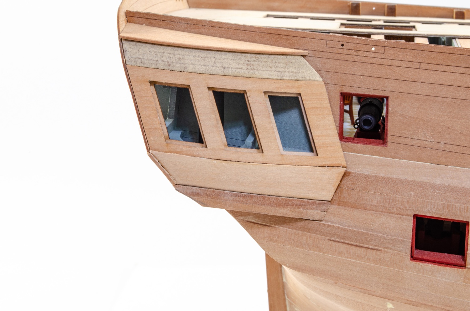
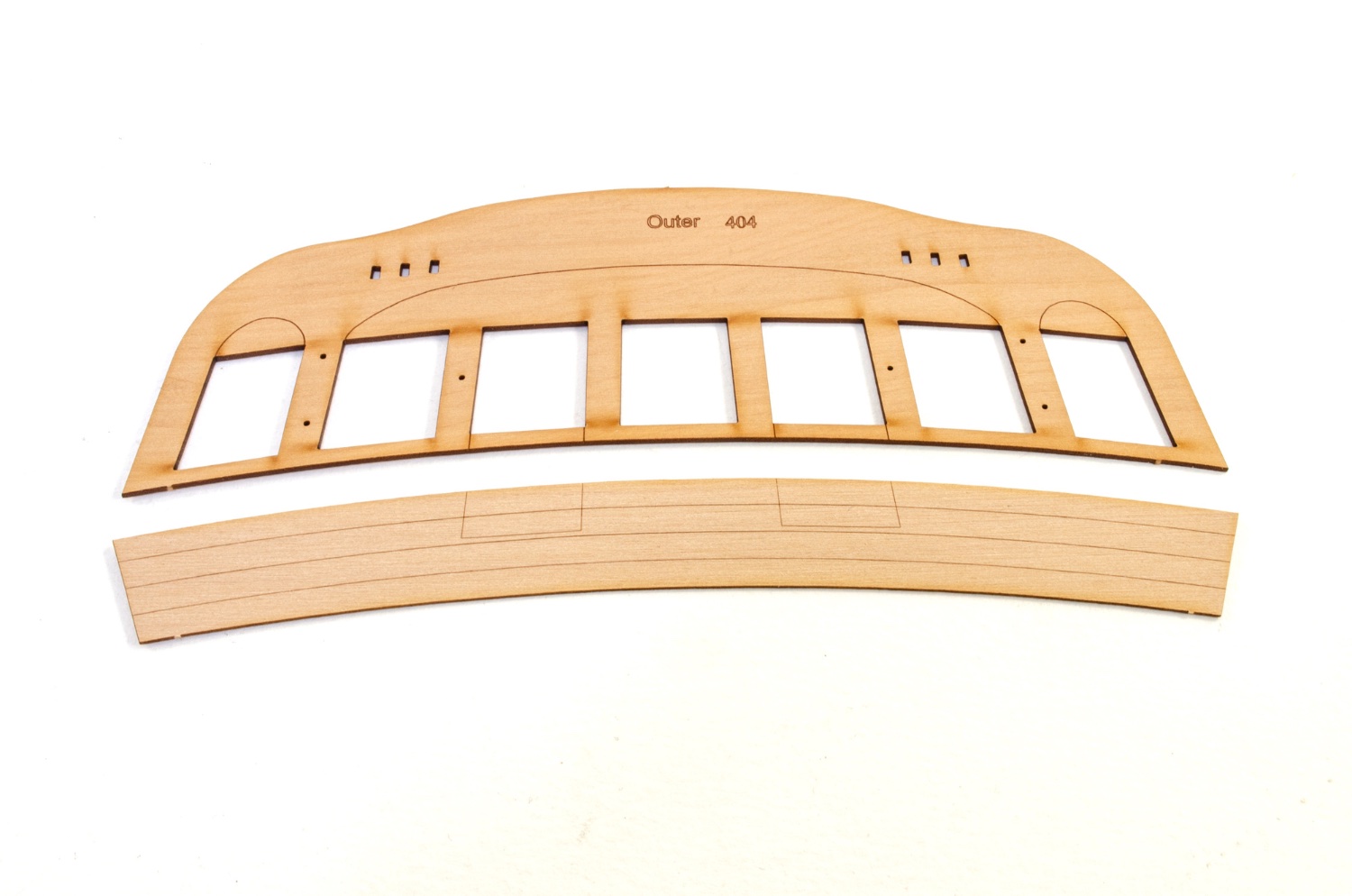
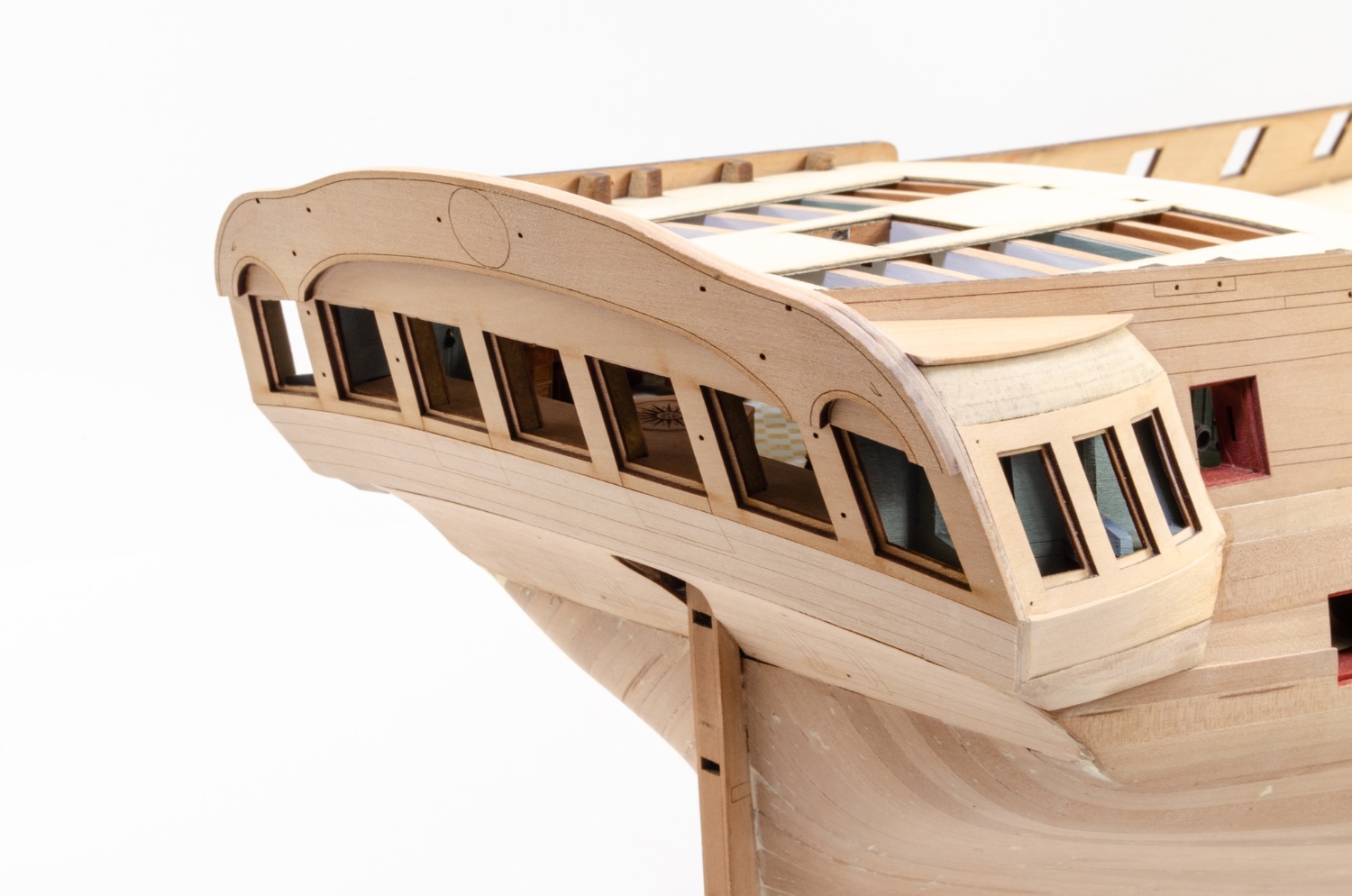
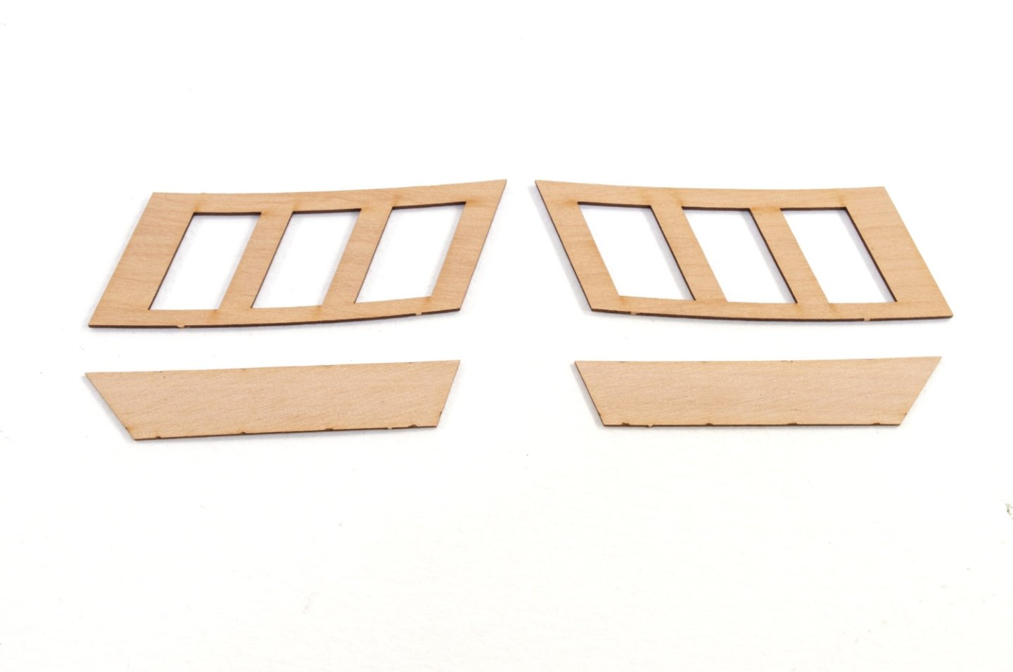
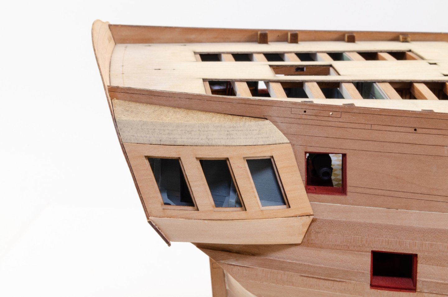
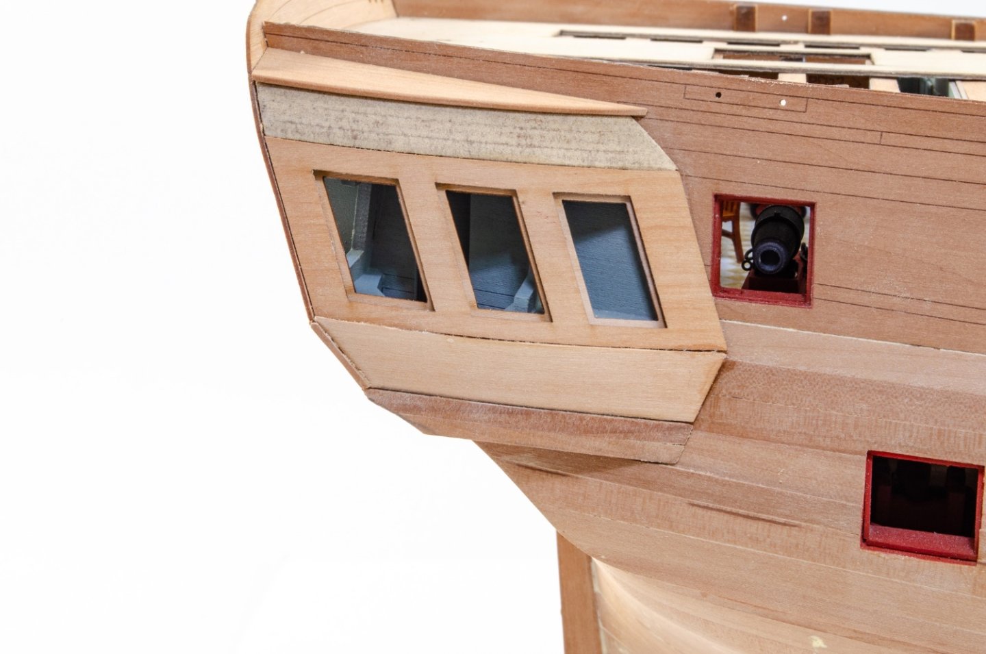
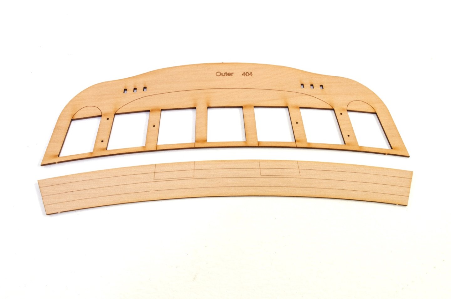
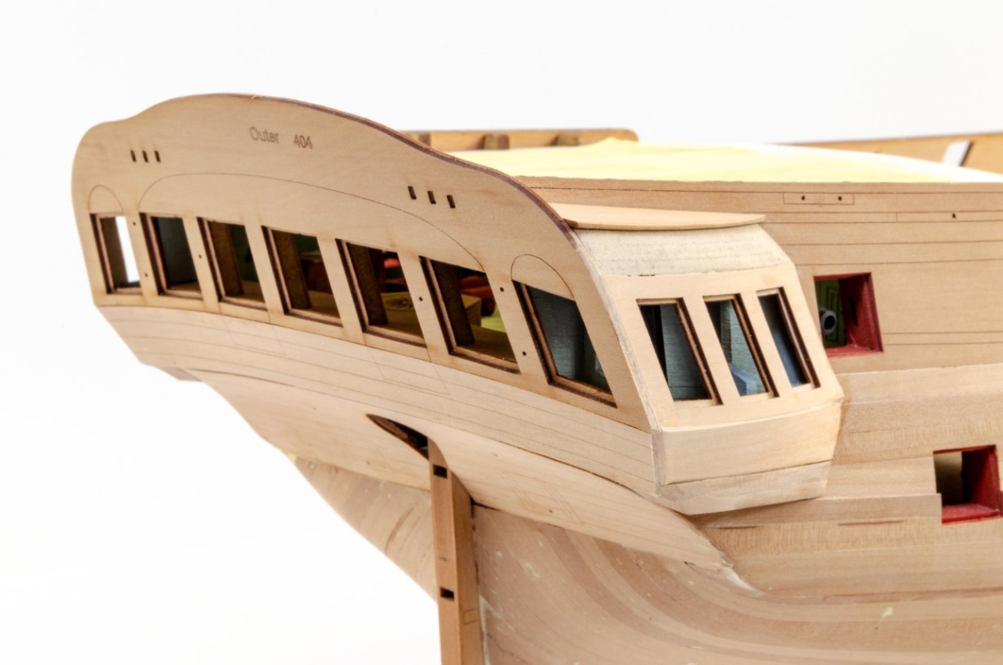
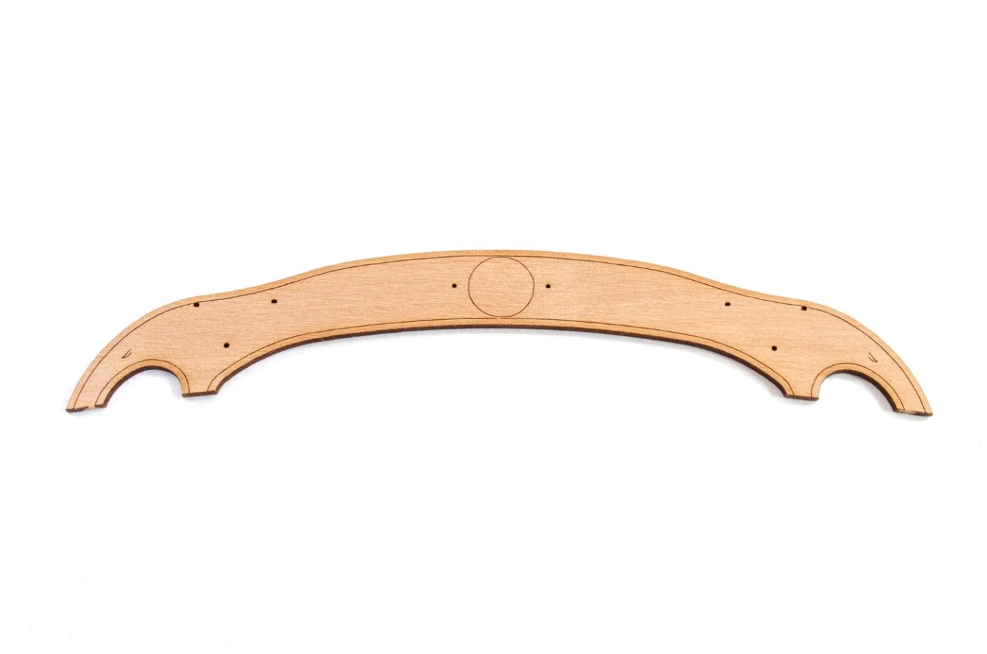
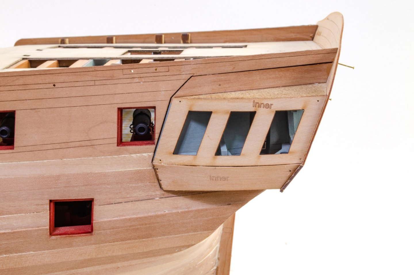
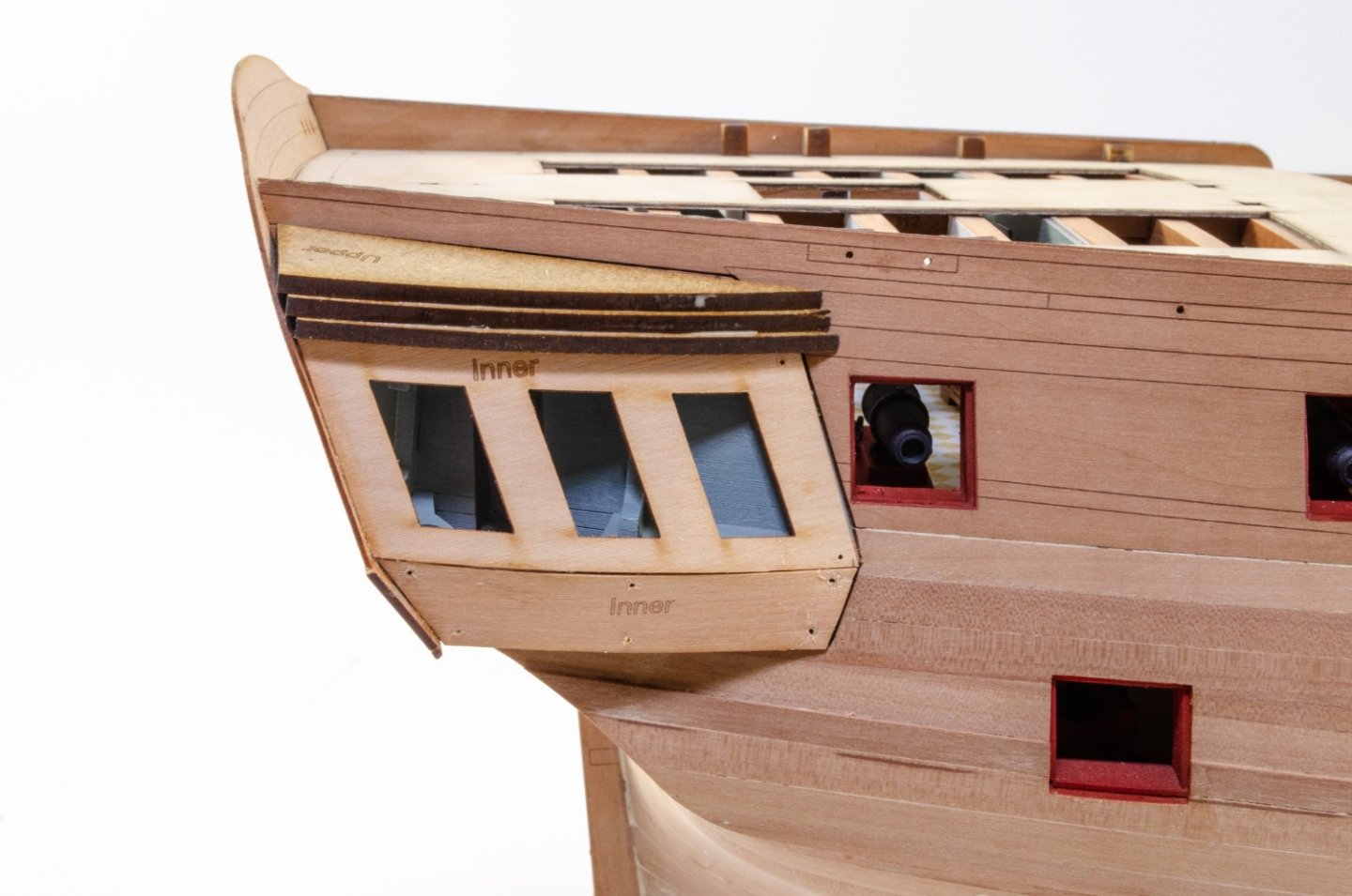
Before I glue the roof into place, it needs to be tested against the gallery once the outer skins are added. WIth those glued into place, the roof is finally trimmed to size and also glued to the model. On top of that is the pear cap which will slightly overlap the shingles that will later be fitted. The pear parts that make the lower galleries are now shaped and fitted. Time to fit the outer stern panel and quarters. I highly recommend you use CA for this so there's no curling of the parts. These are then shaped and the gallery/stern area given a finishing sanding to even up all edges etc. And lastly, the engraved upper stern is fitted and then also sanded into the rest of the hull. More next time...

- 488 replies
-
- 51
-
-

-
- Indefatigable
- Vanguard Models
- (and 1 more)
-
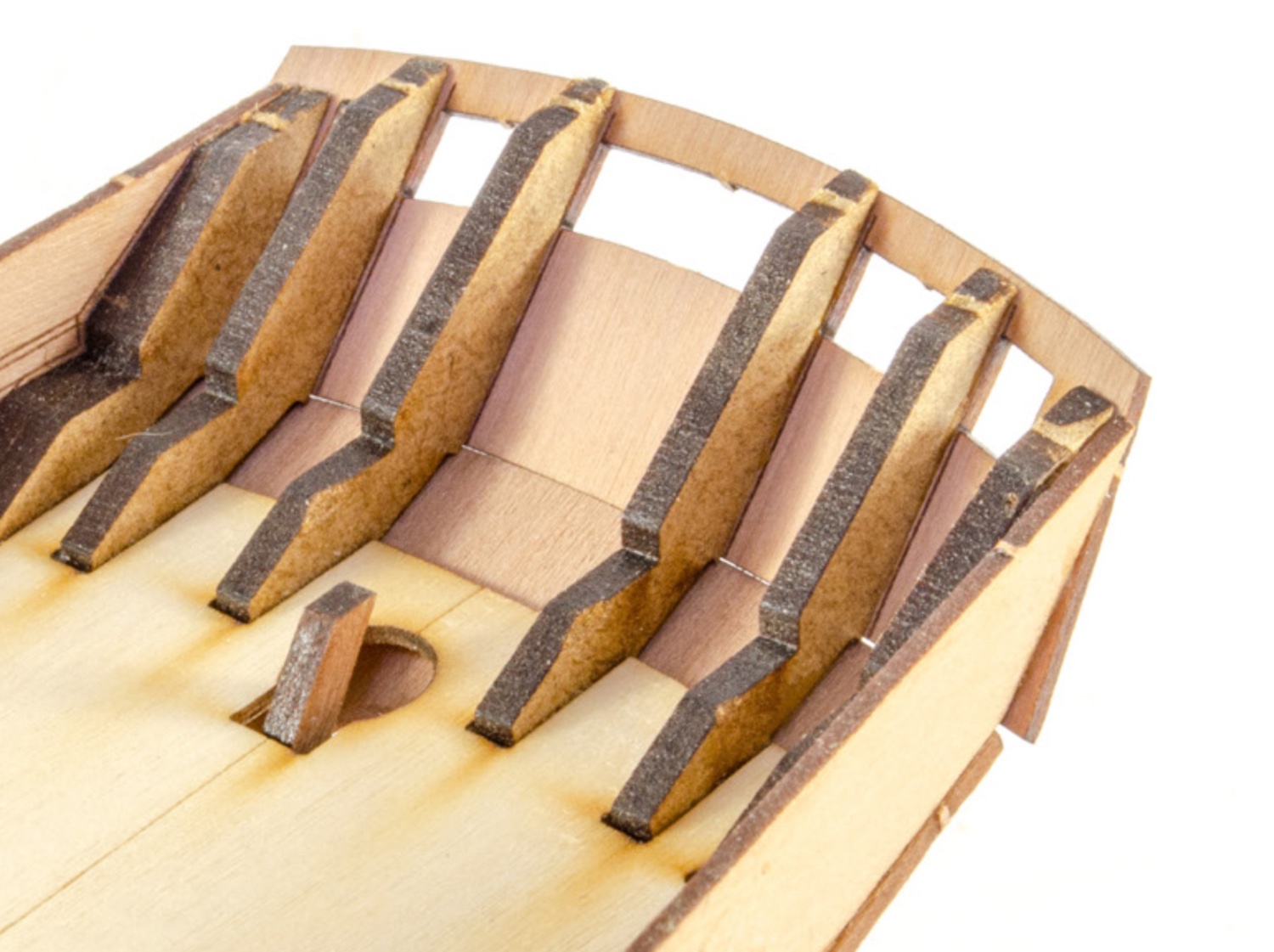
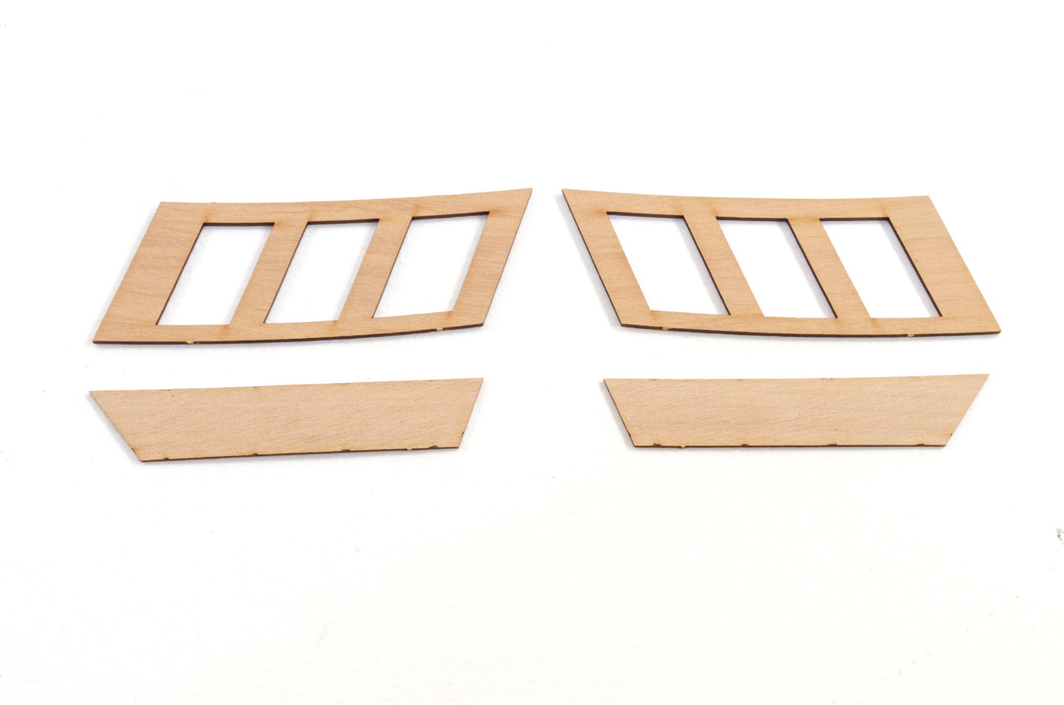
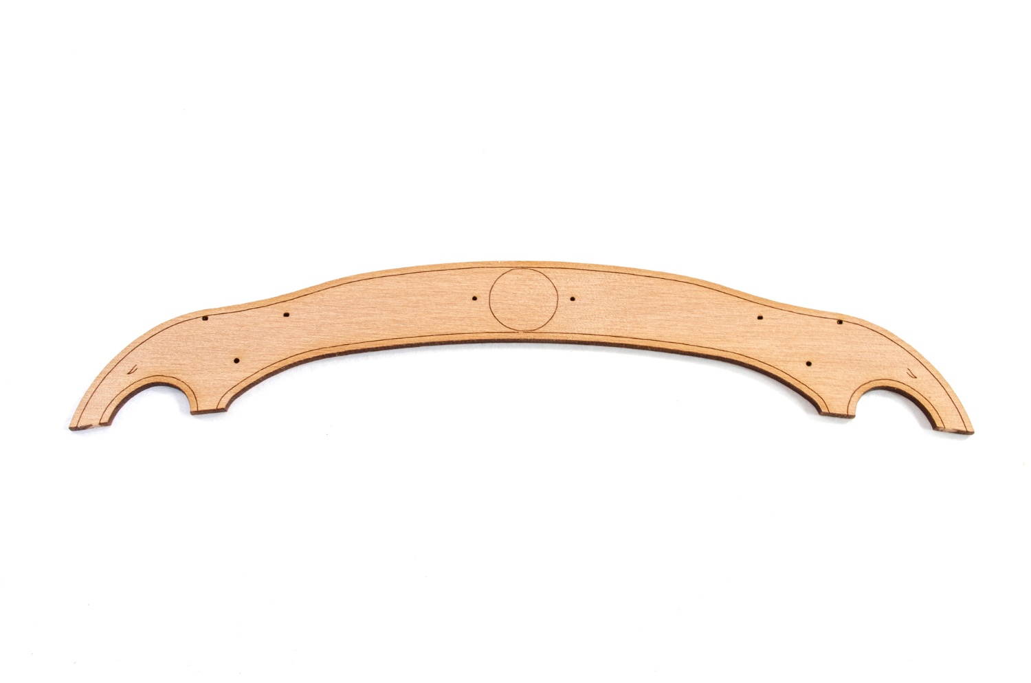
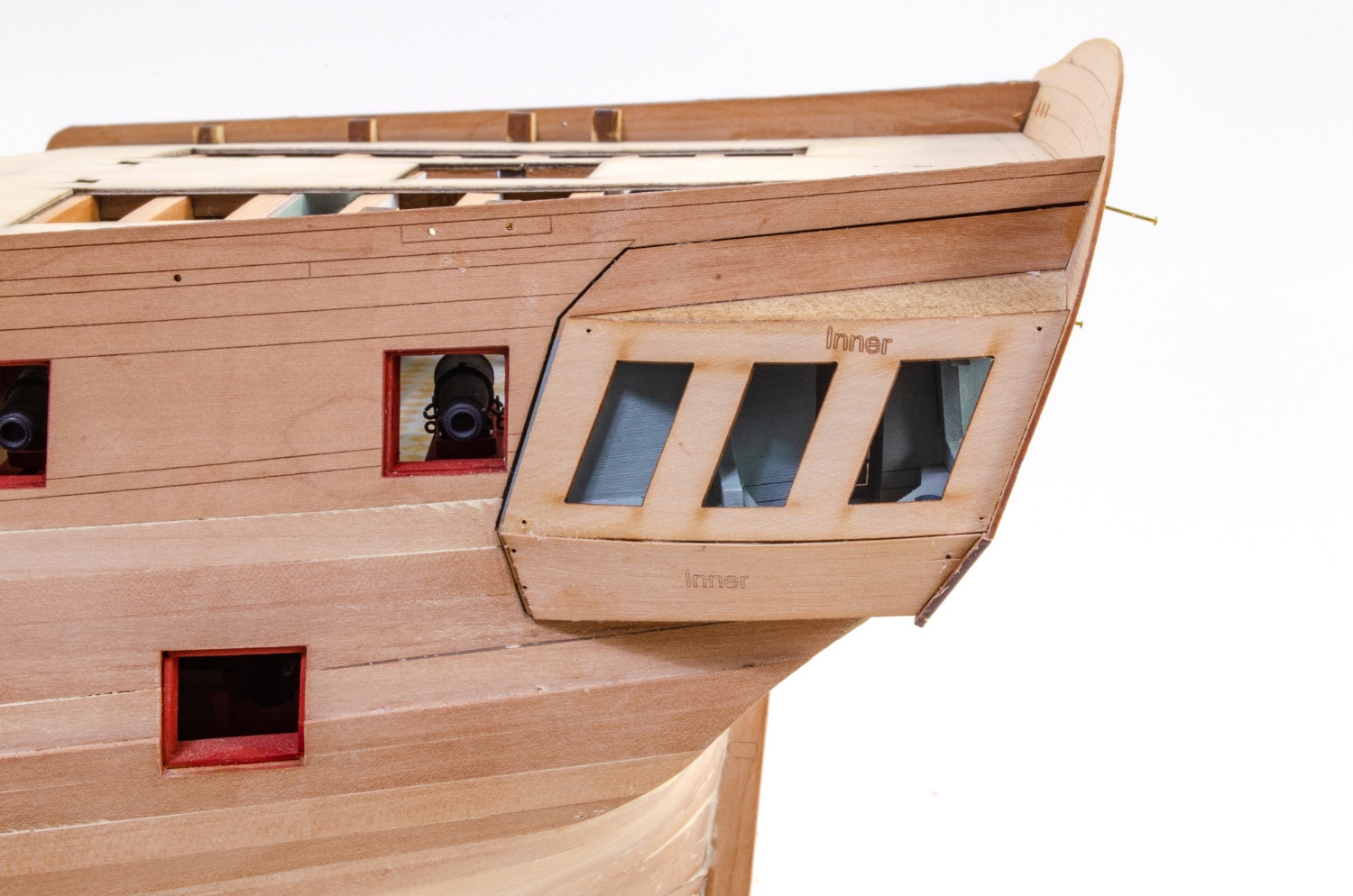
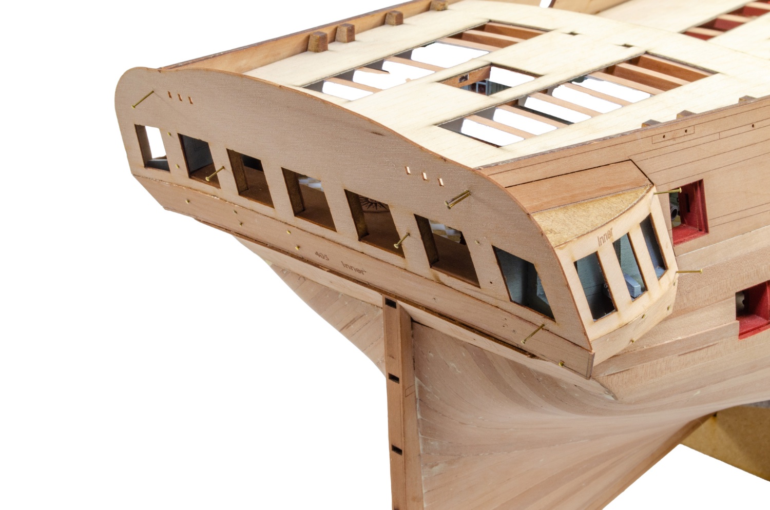
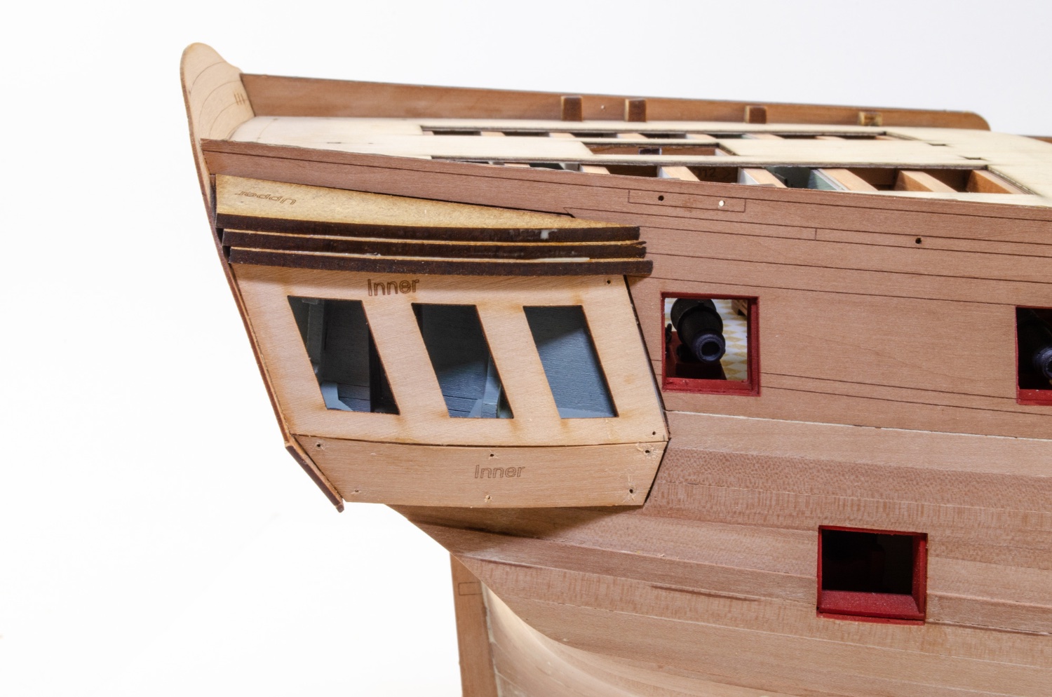
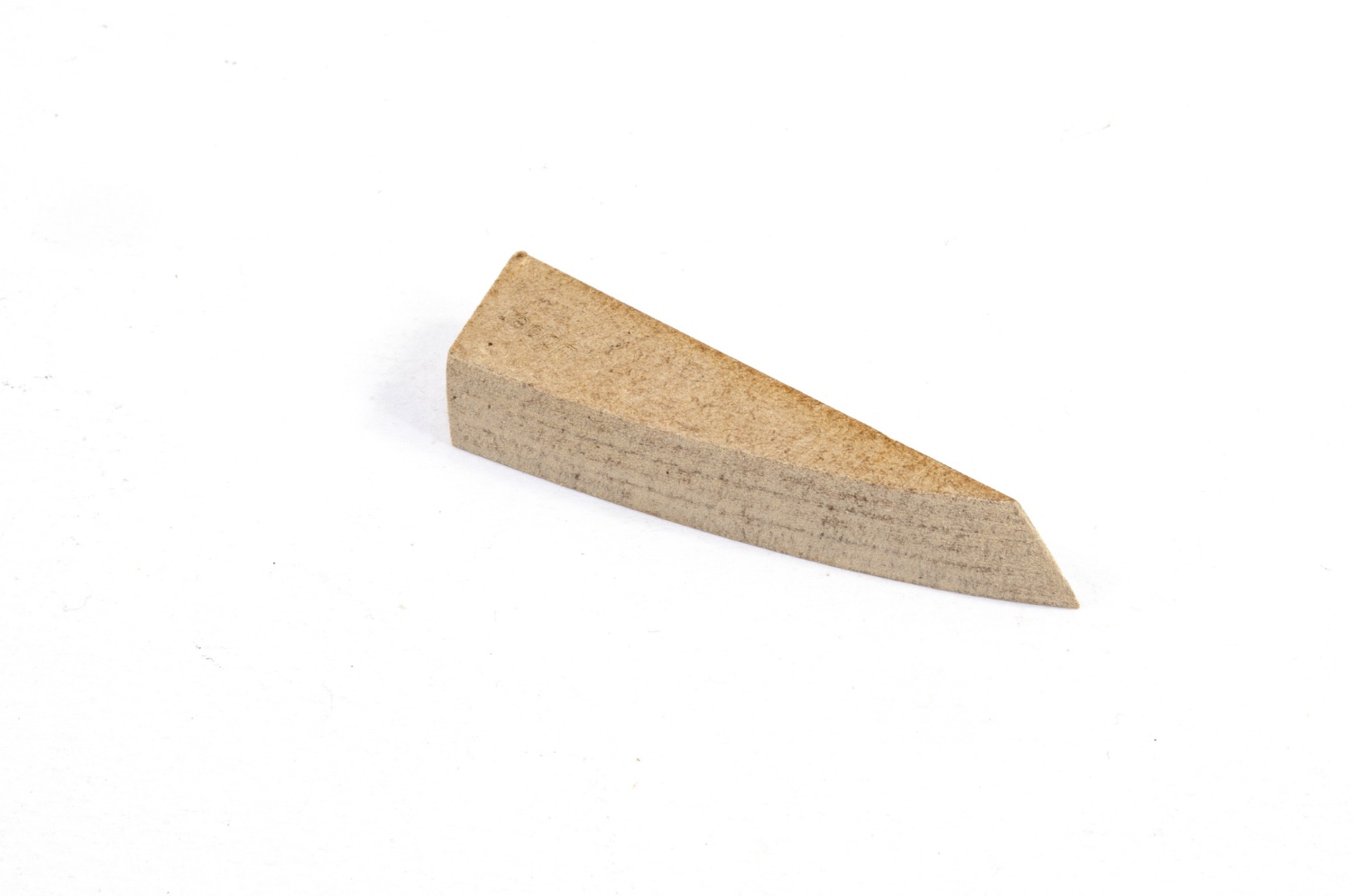
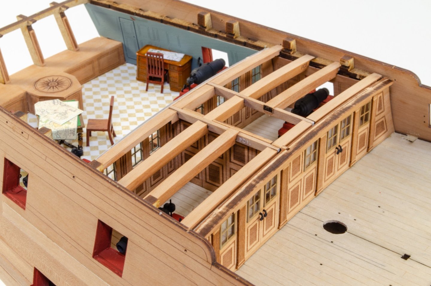
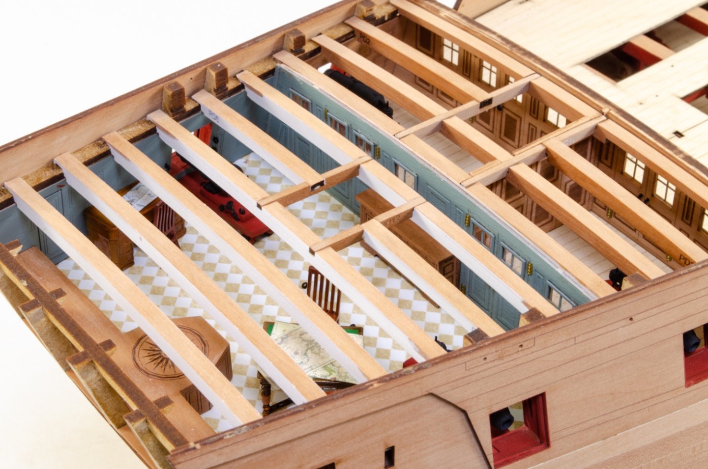
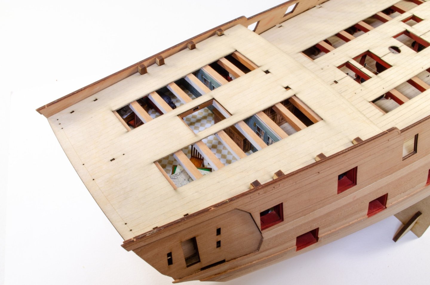
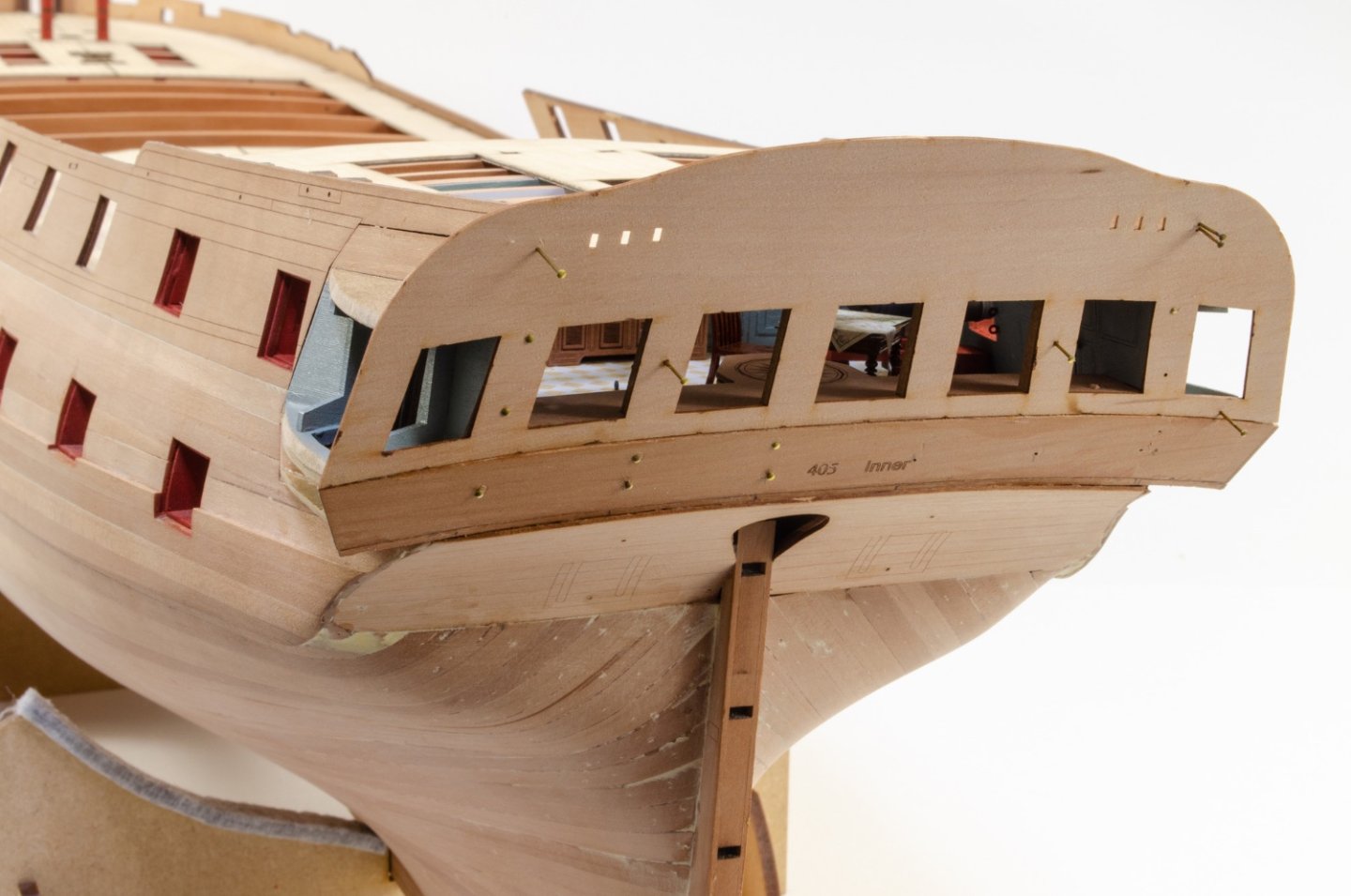
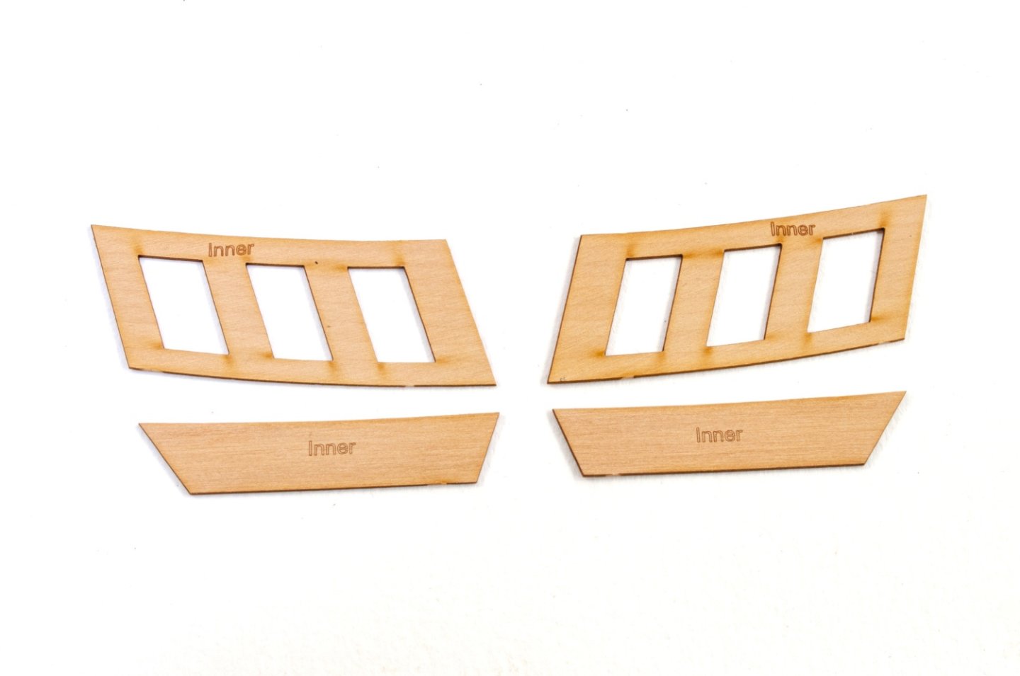
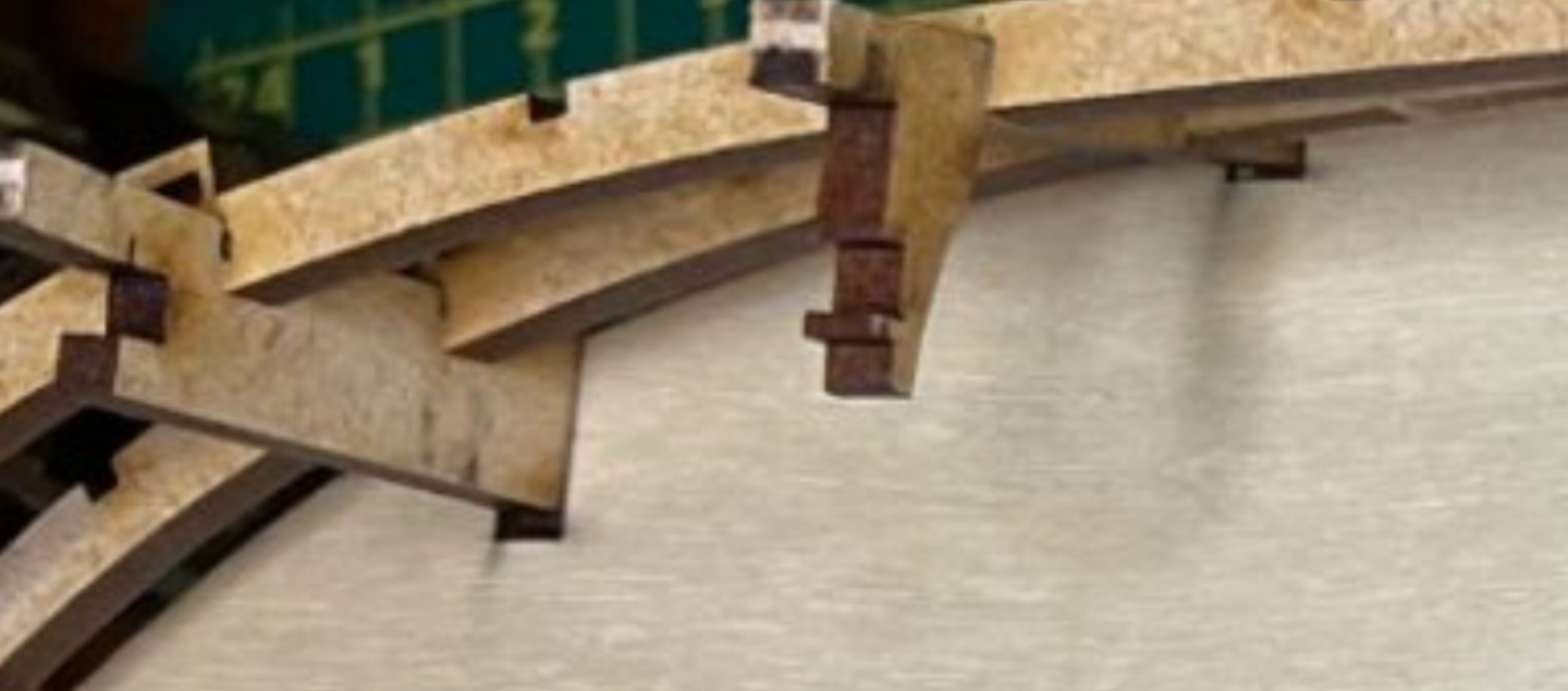
Another update as at least it's now looking a little different. Well, like it or not, the cabin areas now have to be decked over and here you see the beams in the fore cabin area, including the timbers for the original position of the skylight. This was likely moved rearwards when razed. And here you see the new skylight position over the main cabin, which sort of does make much more sense as that area can now be subject to some direct down sunlight. With all beams in place, the 0.8mm laser-engraved ply sub-deck is now installed, notched into the protruding bulkhead ears that you can see. With the poop deck now installed, it's time to turn attention to the quarter galleries. This always gives a hull some character and definition. Here you see the frames, now painted, being glued to the indents on the rear of the hull sides. The inner stern panel can now be fitted, as well as the counter. As with Sphinx, the quarters are sheathed in two layers of timber with the upper parts creating a recessed frame. Here are the inner skins for the galleries. And here is the stern up to this point. Three MDF layers are used to create the roof, except for a pear caping piece that's fitted soon. These will eventually be painted black and covered with laser-cut shingles. The reason for the layers is that it makes it easier to sand to the correct angles as you temporarily sit them on the hull side. After fettling, the finished roof will look like this.


- 488 replies
-
- 35
-
-
- Indefatigable
- Vanguard Models
- (and 1 more)
-
In fact, you can see the deck isn't properly located as it should be. Take a look here at the gaps between the ply deck slot and the bulkhead ears:
-
The comparison of the engraved deck to the ply sub deck is correct. The engraved part is smaller as it doesn't extend into the bulwark area. The problem you have with fitting the ply decks is definitely that the halves aren't pushed completely back into the slots in the bulkhead ears, no doubt. The deck width across each bulkhead I a set width, with zero variation between kit. Try using a jewellers file to remove the char from each ply deck slot, and also slightly bevel the upper, innermost part of the slot so that it catches the notch in each bulkhead ear. I absolutely guarantee that this is the cause. I've seen this a couple of times before and know this is the issue. Just be careful in your test fitting to make sure the deck halves are slotted in 100%.
-
Doesn't it feel great to have finished something as complex as Sphinx! Well done, and it was definitely a nice move in starting over too. If I have one suggestion it would be to re-angle and tidy up the hammock cranes and rope along the gangways. ✌️
- 476 replies
-
- 5
-
-
- sphinx
- vanguard models
- (and 1 more)
-
It'll be a little difficult on a fully rigged ship. You can open things up more if you wanted though.
- 488 replies
-
- 7
-
-
- Indefatigable
- Vanguard Models
- (and 1 more)
-
I re-took the photo of the cabin area as there was too much glare on the deck and the background was dirty. So, here it is.

- 488 replies
-
- 34
-
-
-
- Indefatigable
- Vanguard Models
- (and 1 more)
-
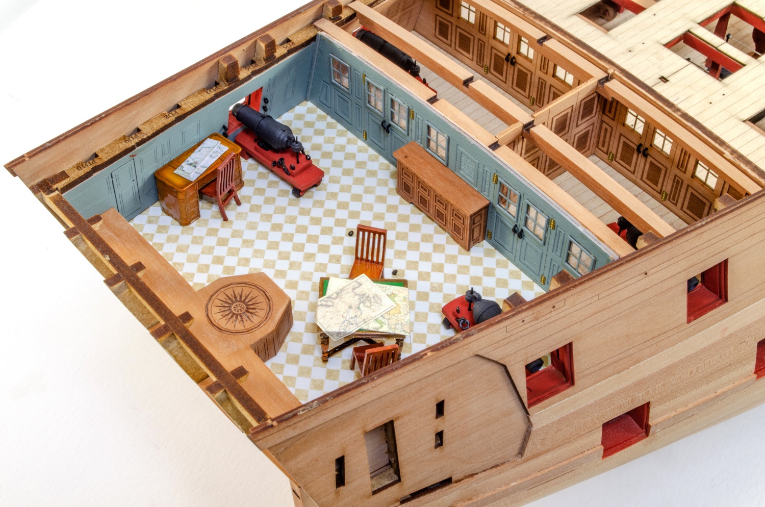
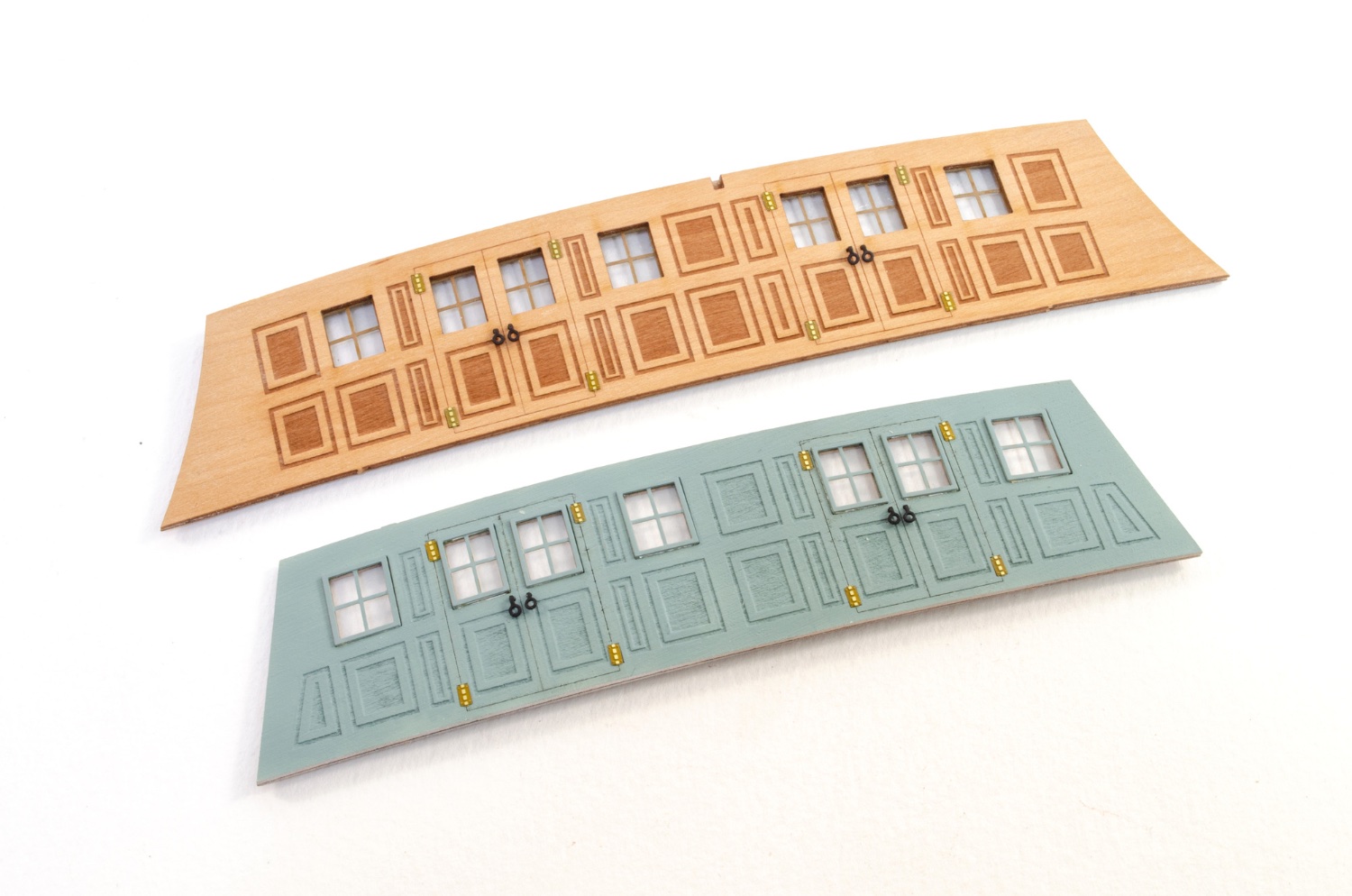
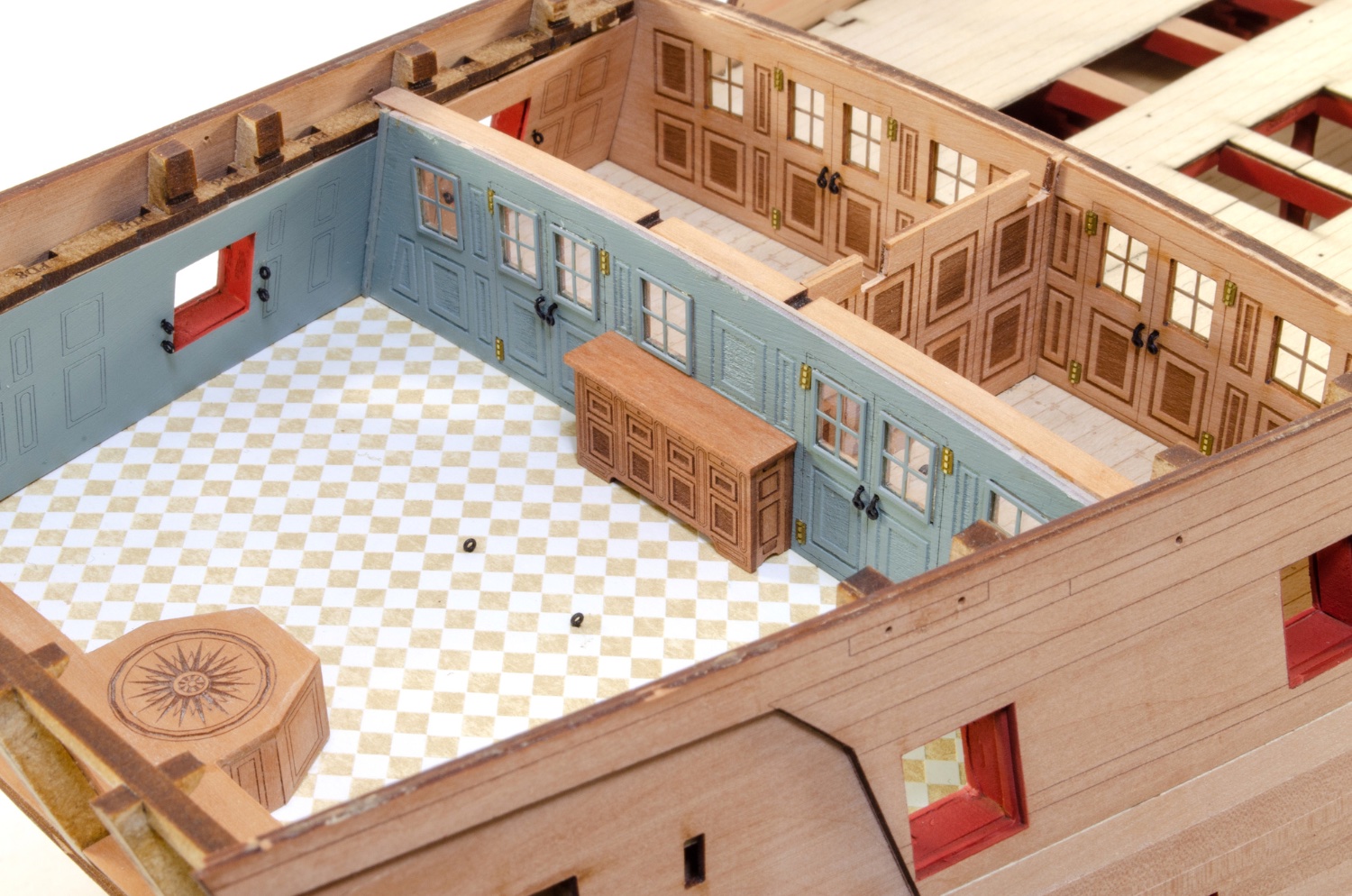
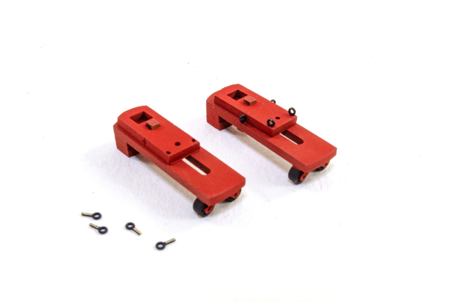
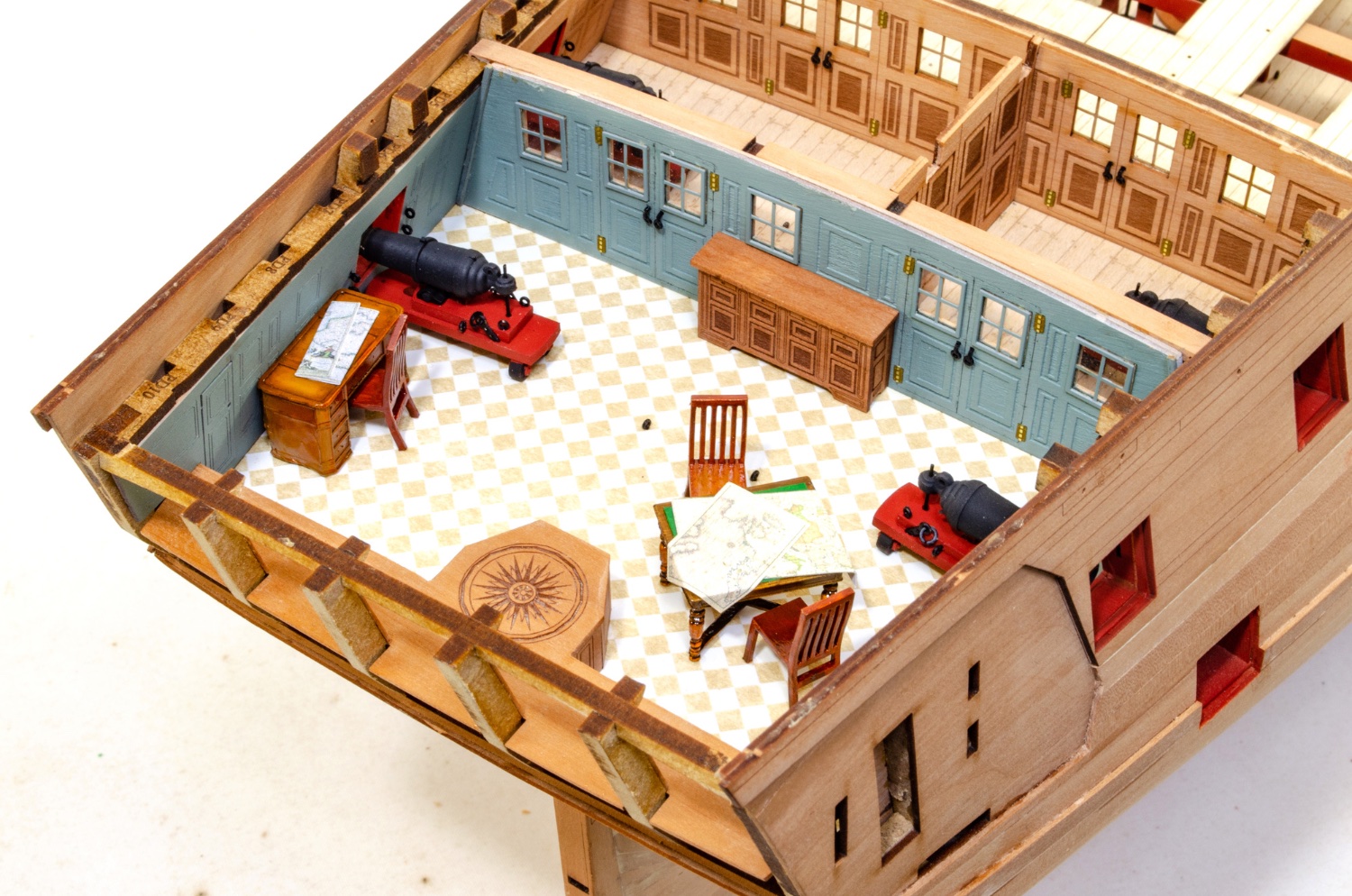
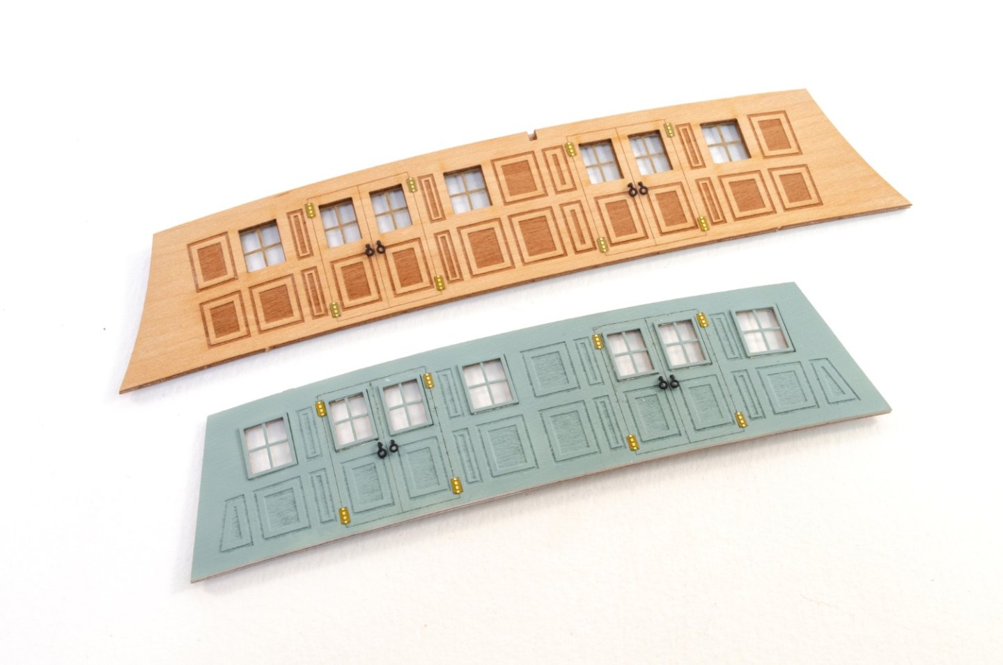
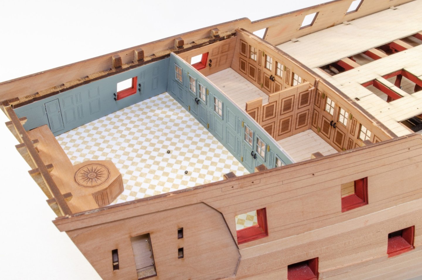
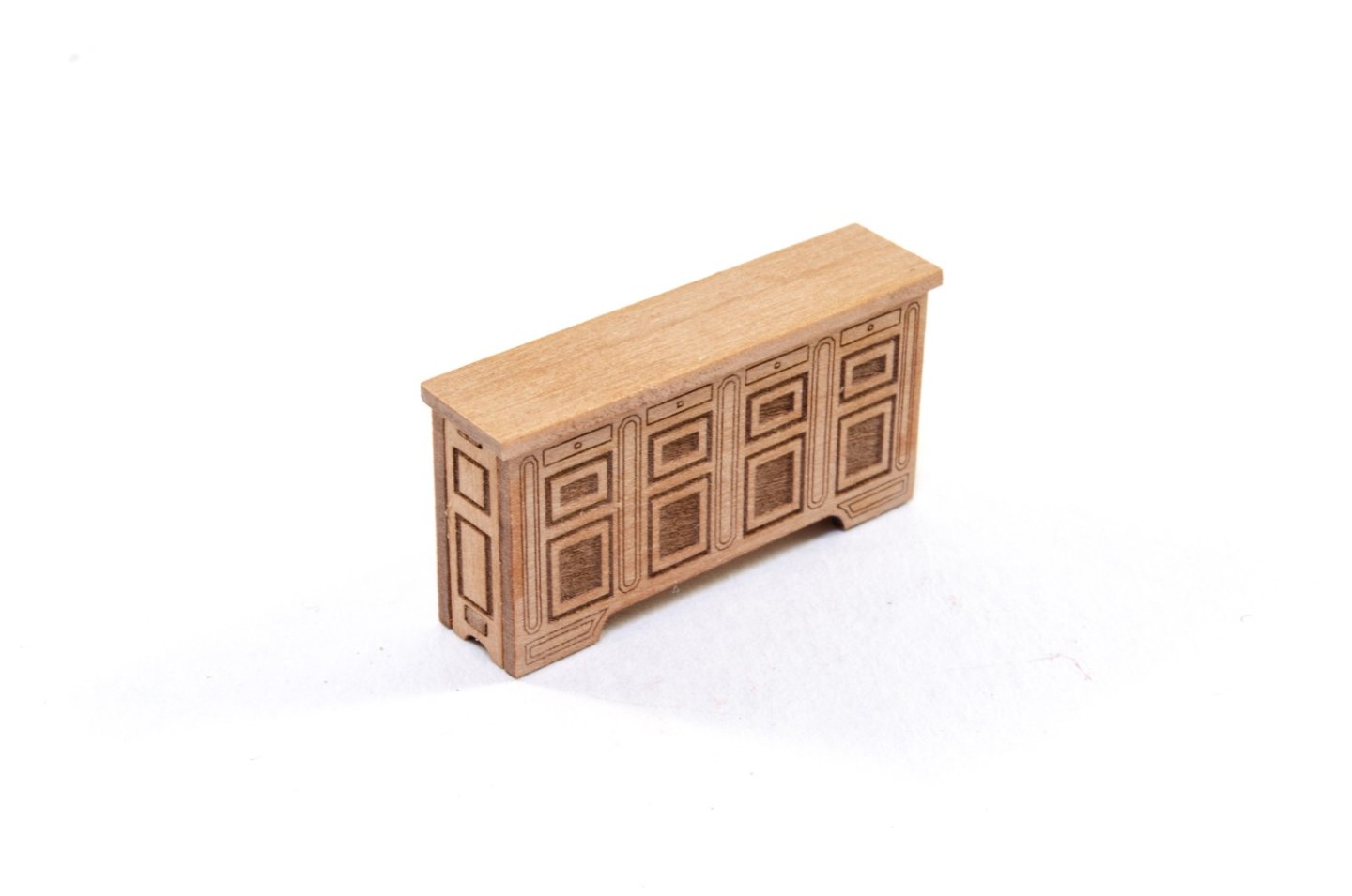
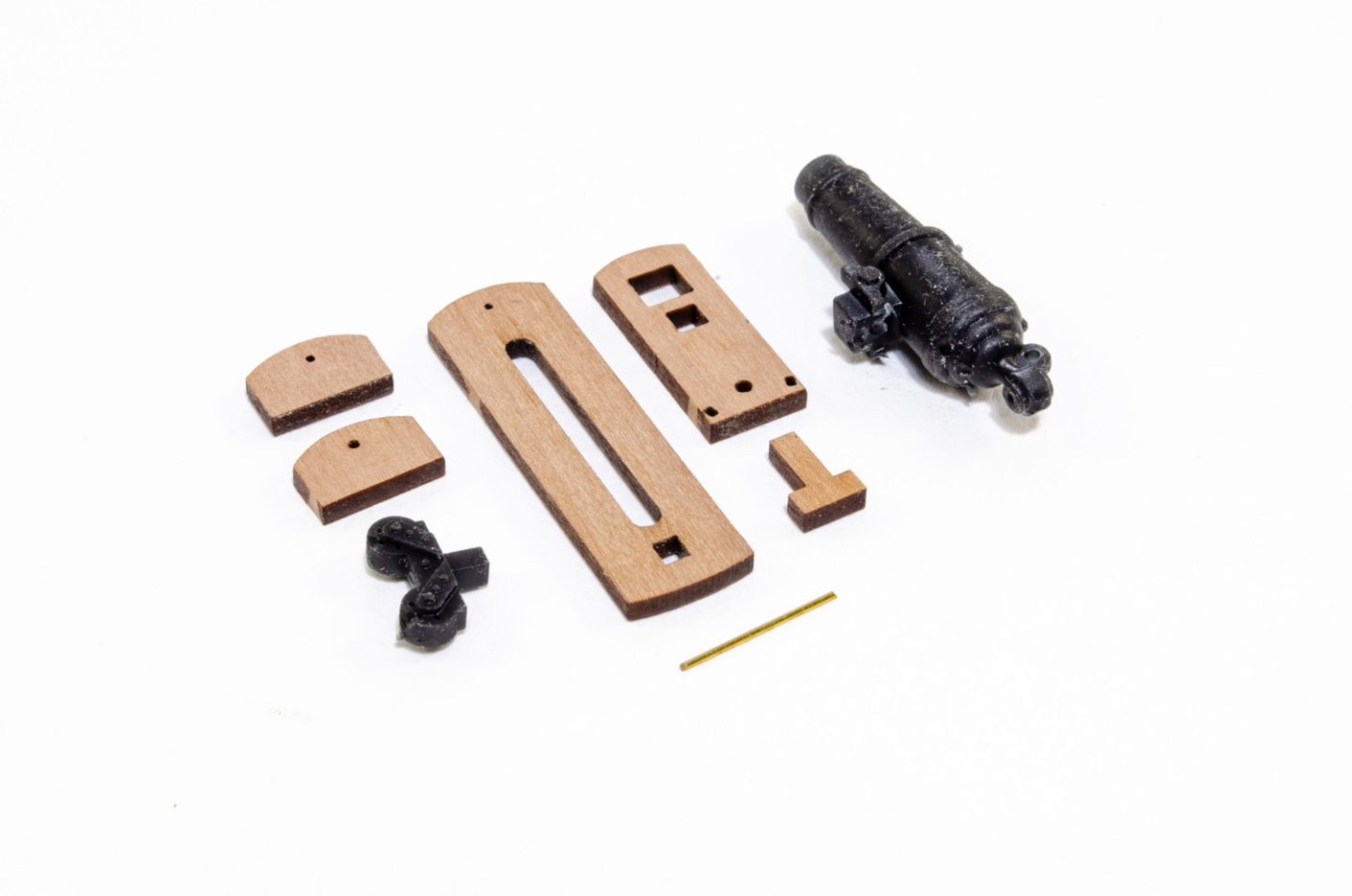
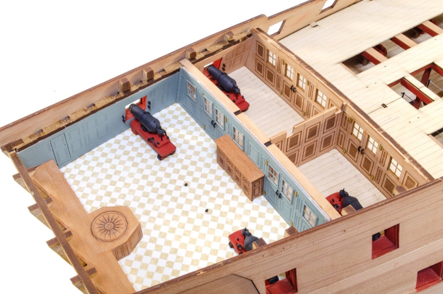
The cabin walls and internal cabin screen are now painted, and the screens fitted out. I can finally glue into place the cabin walls, screens and partition. Note the eyelets are added to the ports and floor. Did I say this came with a cabinet? No? Well, it does, and this is now fitted into place. The carronades in this area differ from the others as they will retract into hull during the hull painting process. They can be rolled out into position when that job is complete. These are now fitted to the cabins area. Time for some furniture and maps too. Hope you like the work so far. Onwards!!


- 488 replies
-
- 50
-
-
-
- Indefatigable
- Vanguard Models
- (and 1 more)
-
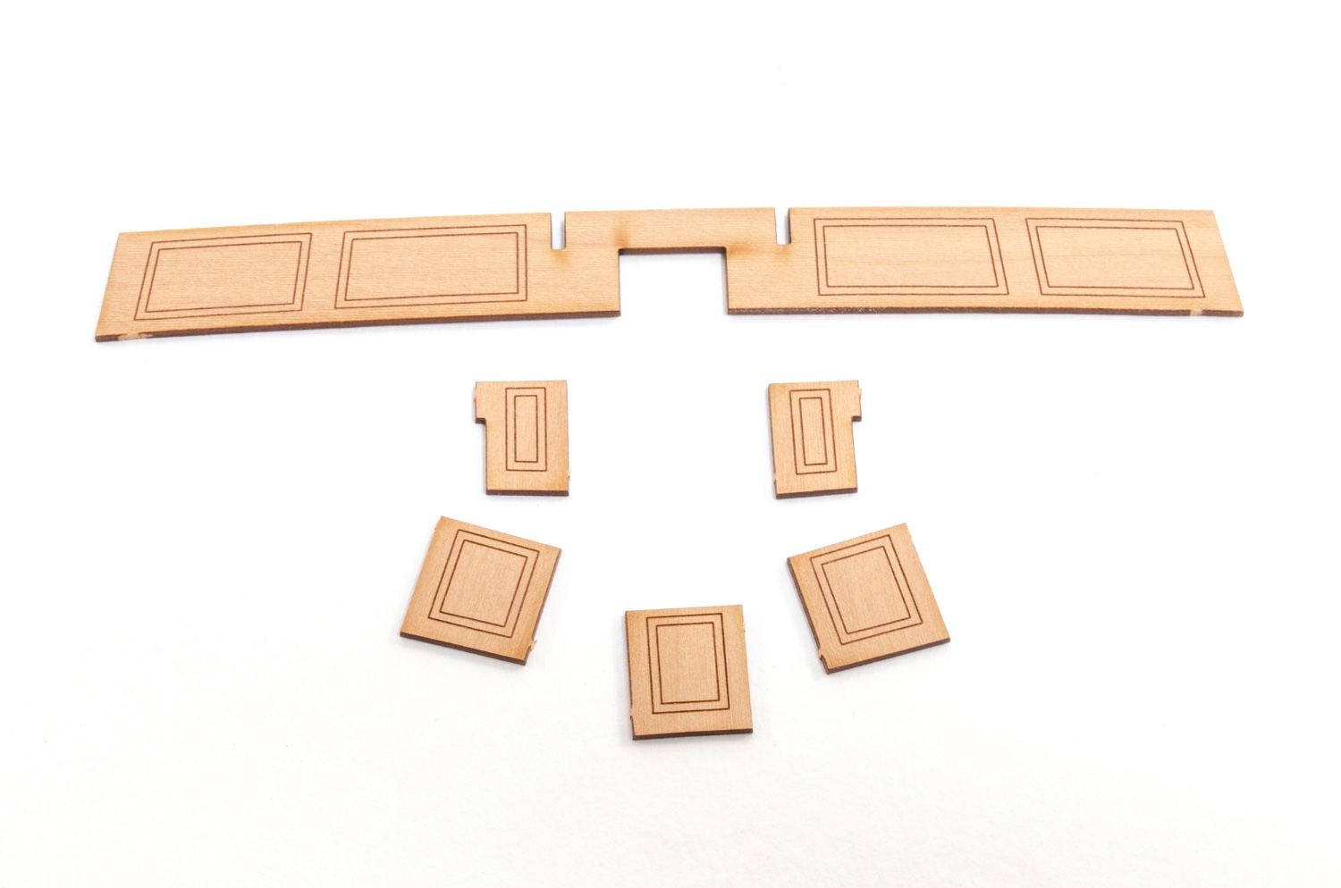
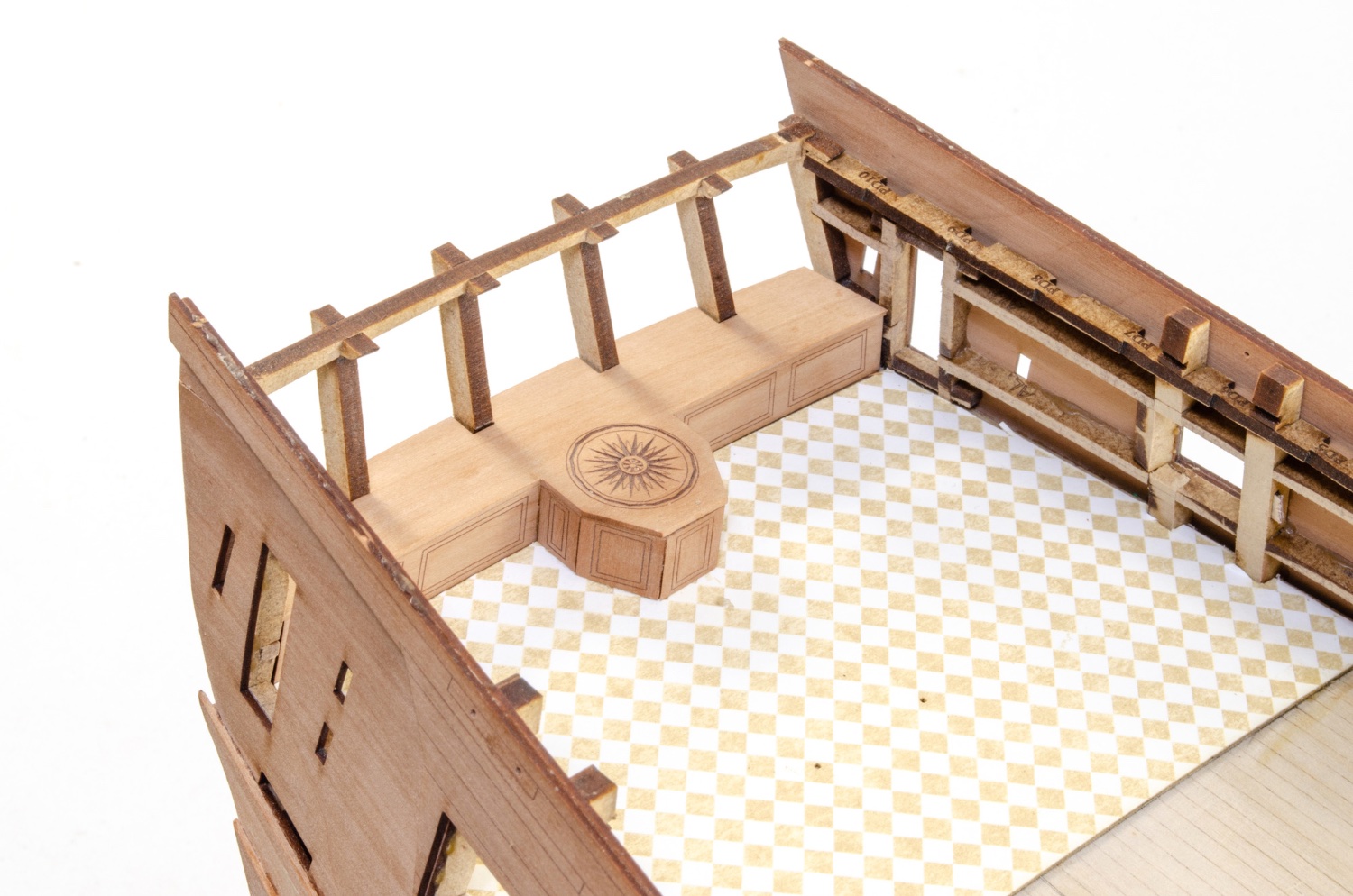
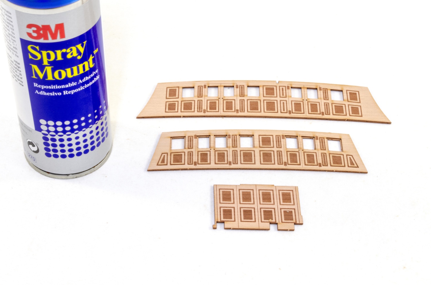
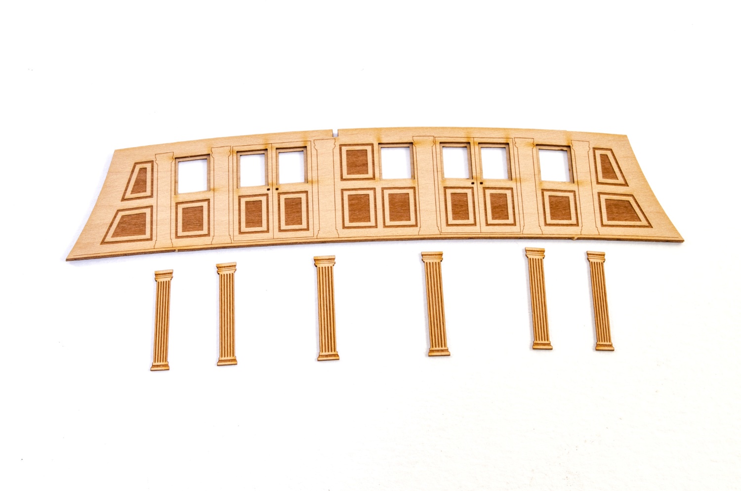
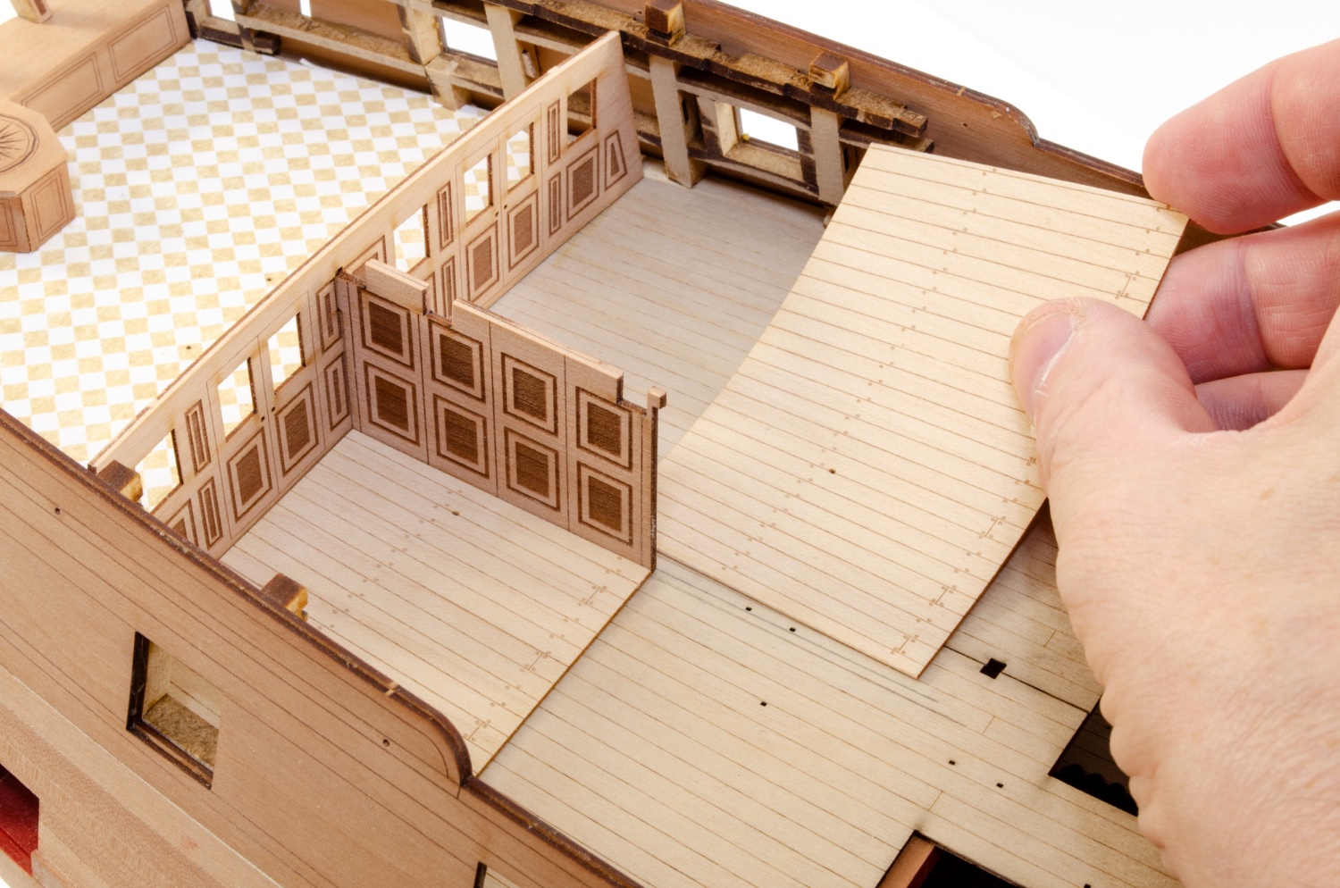
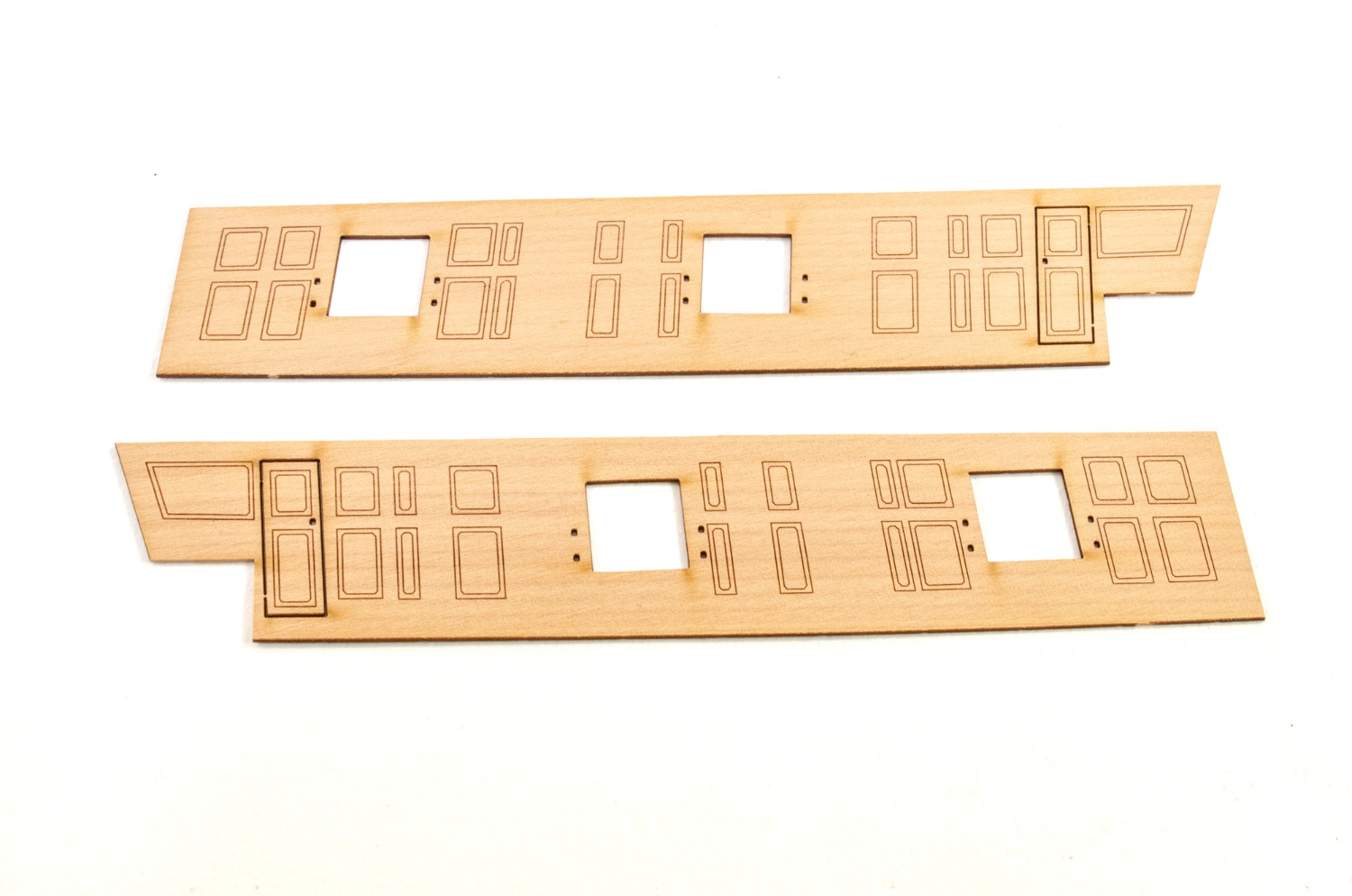
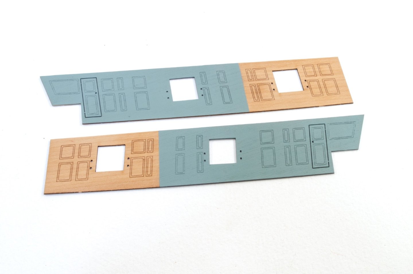
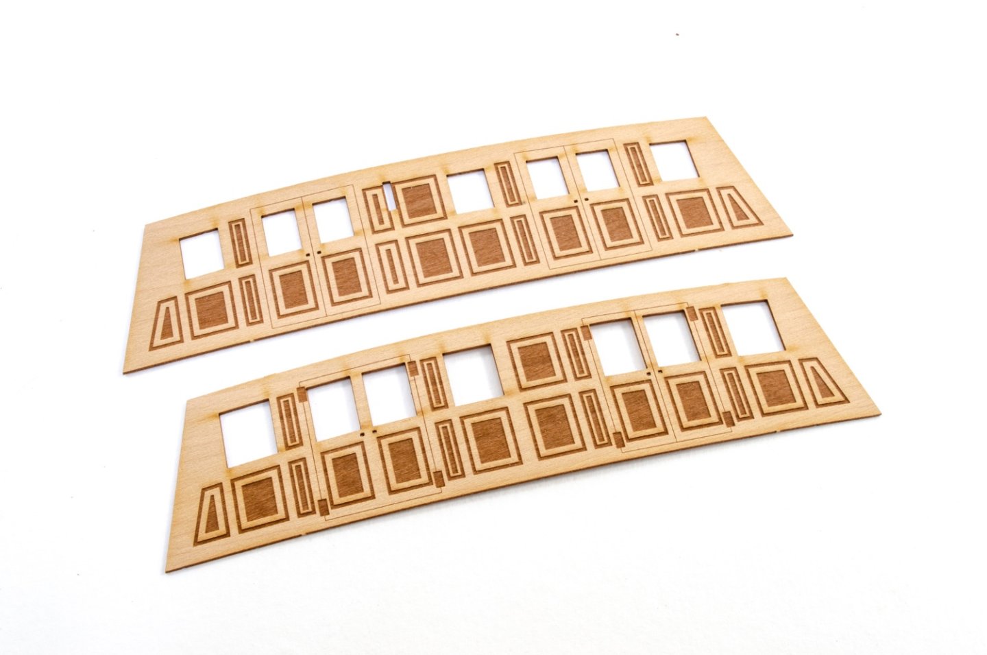
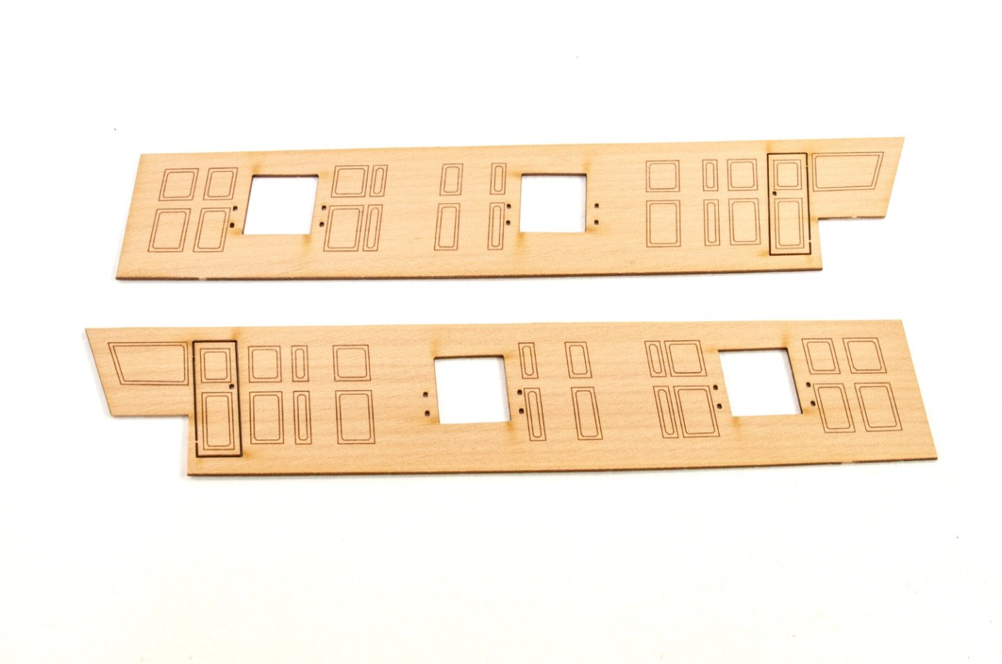
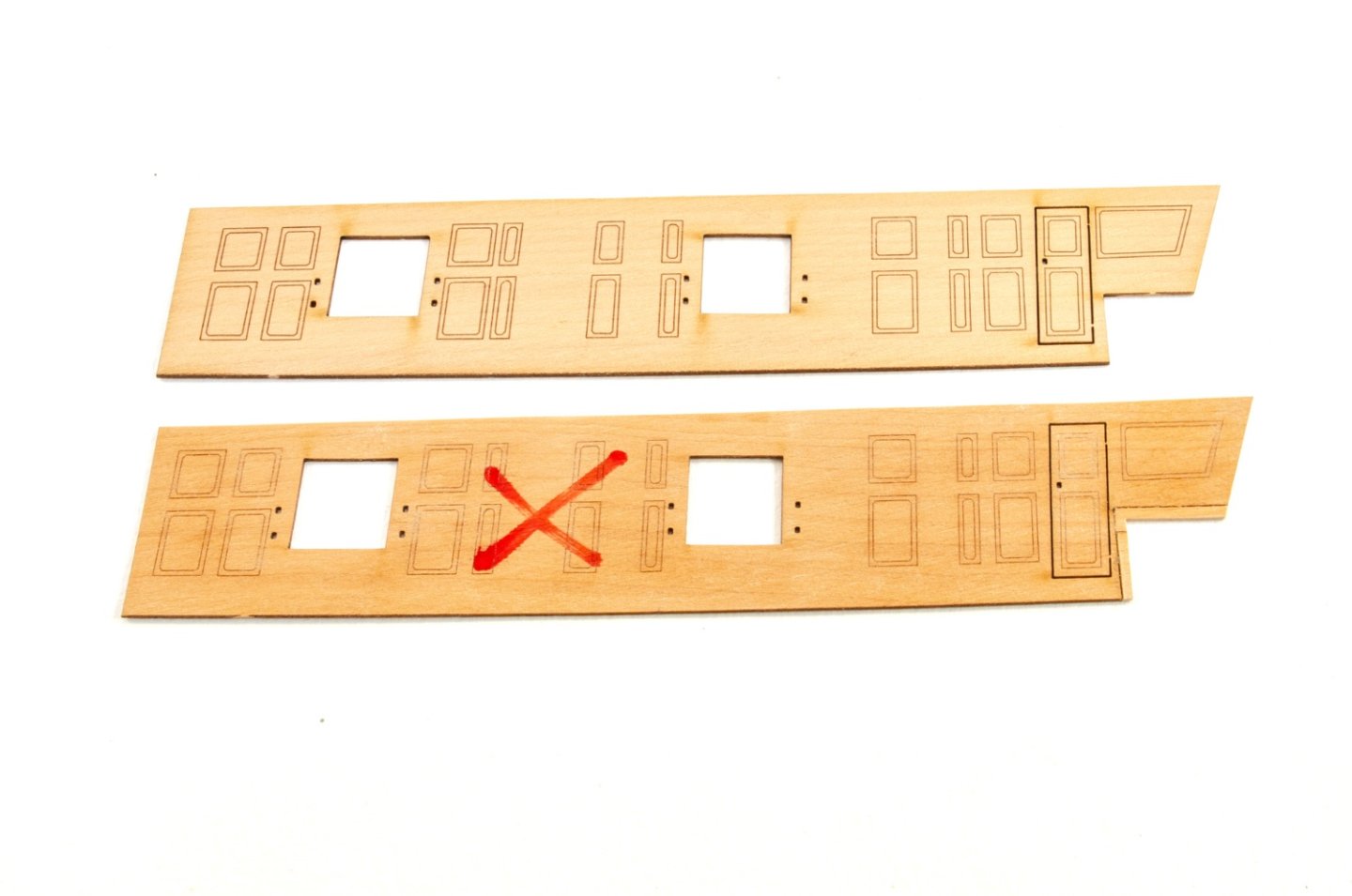
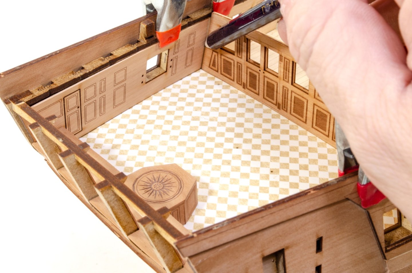
This is my weekend update time as I'll be working flat out from this stage to get the upper deck work done. Getting the cabin built and fitted out seemed like a good time to post. The first thing that's to be done is to fit the vertical face for the benching in rear of captain's office. With that fitted, the parquet floor is added. This is supplied in card and it looks nicer than the maple version, and a cool contrast. Titebond is used to fit this. The remainder of the rudder housing boxing is then completed. The bulkhead screens are supplied in two 0.6mm engraved laminates. Instead of using wood-curling white glue, 3M Spray Mount is used. The parts are lovely and glass flat. The outer bulkhead screen is fitted with laser-engraved columns. The inner bulkhead screen and the partition wall are temporarily fitted so that the engraved maple floor sections in that area can be trimmed to size. Once they are done, the floor sections are glued into place and the screen and partition removed until later. This picture will give a good idea about the post design process that I am engaged in when building the production prototype. I will invariably find a small number of things which needed amending. This is either because it was missed during the initial cut build, or because something in the design was changed and a small number of affected areas may have missed an update. Here you see the cabin side wall and the changes made from the initial part. That includes shifting details by 2mm to align gun ports and also packing out the rear to cater to the lowered cabin shelf. Hey, at least we can show you how we do this as a tag-team! I temporarily fit the cabin walls and the screens so that I can draw a demarcation line to guide me for painting the cabin interior.


- 488 replies
-
- 27
-
-
-
- Indefatigable
- Vanguard Models
- (and 1 more)
-
Posting in my capacity as part-time VM employee (😆), this is to let you all know that today is the last day of the VM Summer Sale, with 10% off all VM kits, except for Ranger, as that's a new release. If you want a nice discount on a fisher, Duchess, Sphinx, Flirt or Speedy etc. NOW really is the time to pull the trigger! https://vanguardmodels.co.uk
-
Welcome to MSW! Quick note: if you paste text from another site, it will copy the formatting. If you then click the 'Paste as plain text instead', then the post will look normal.
-
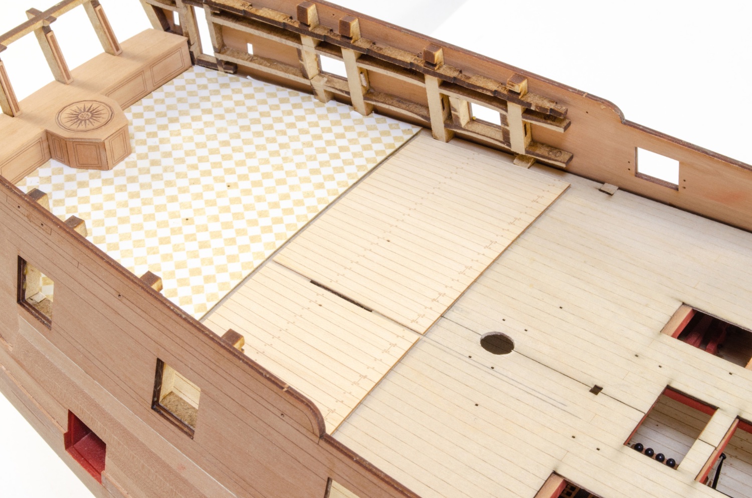
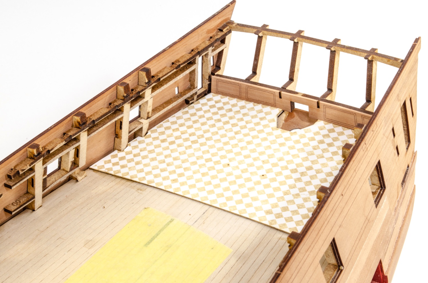
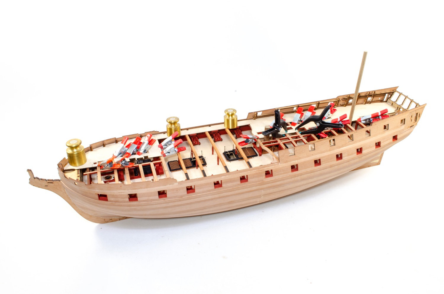
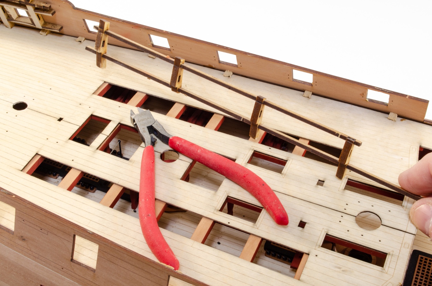
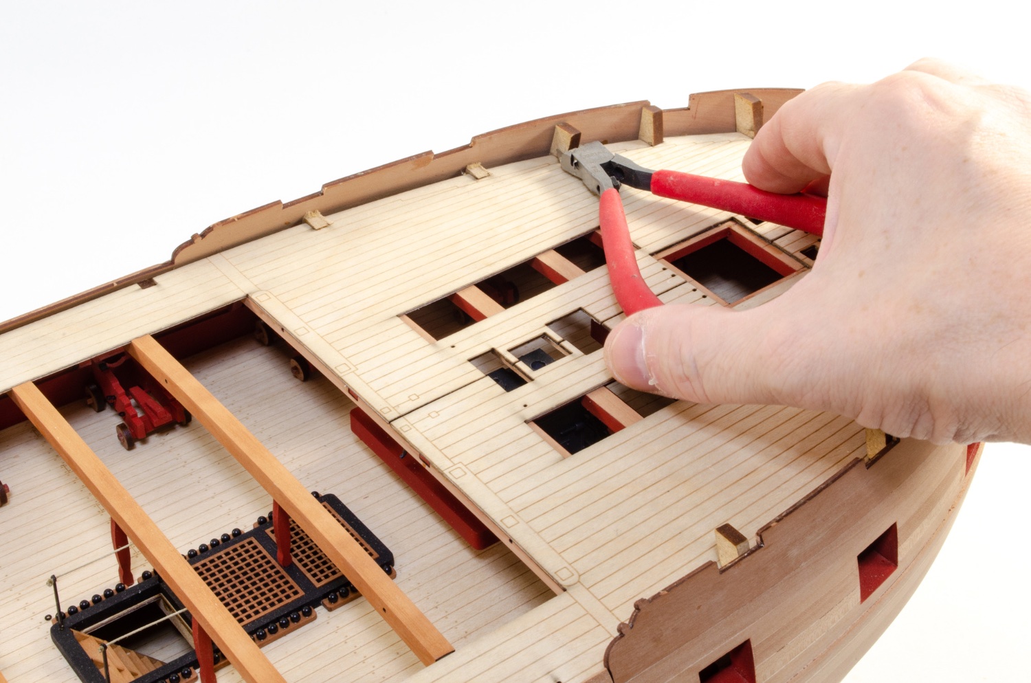
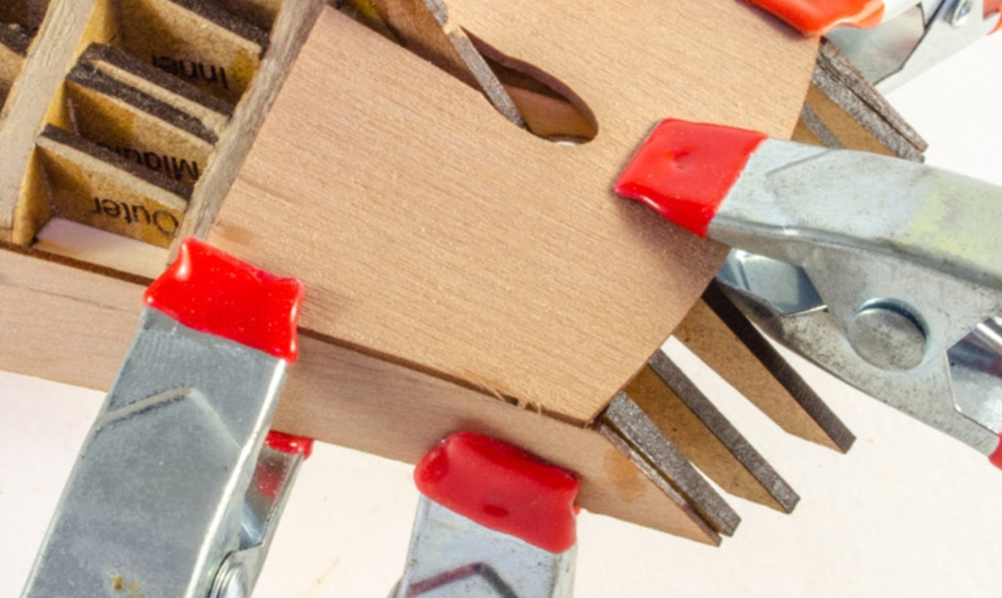
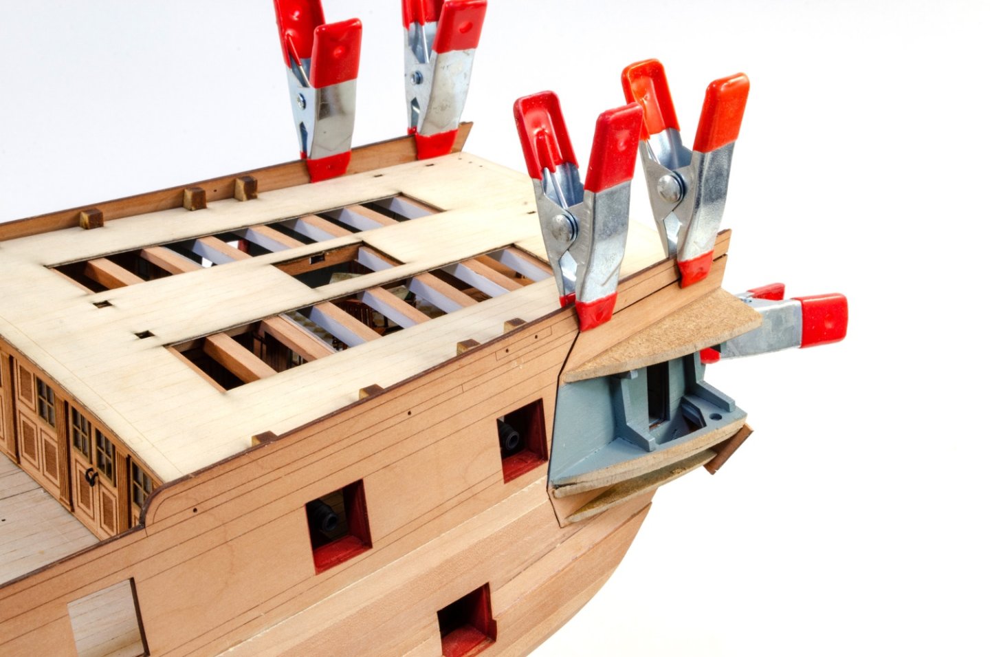
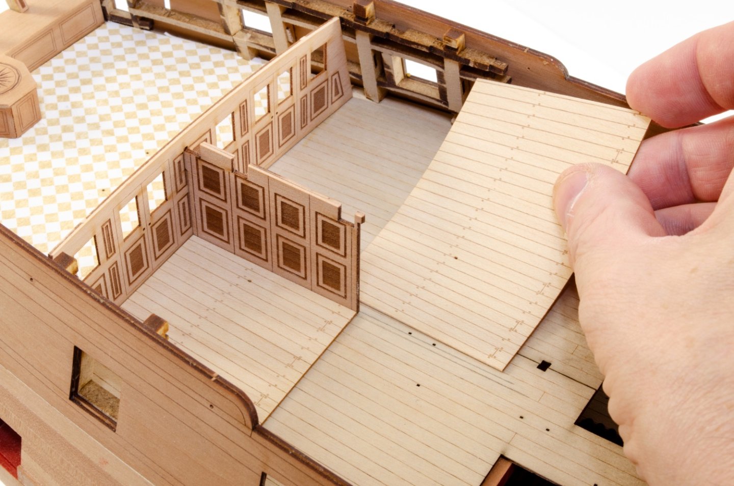
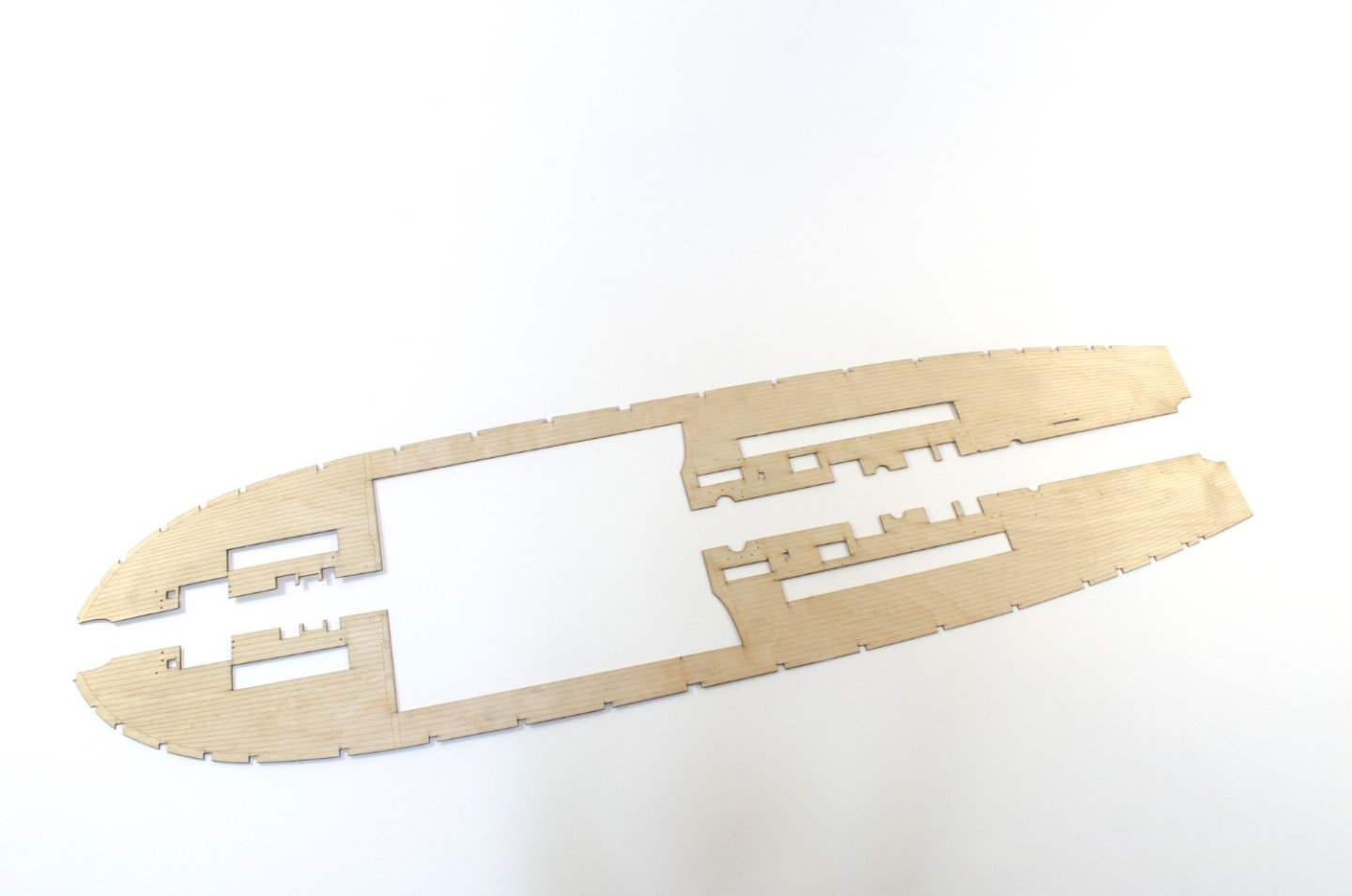
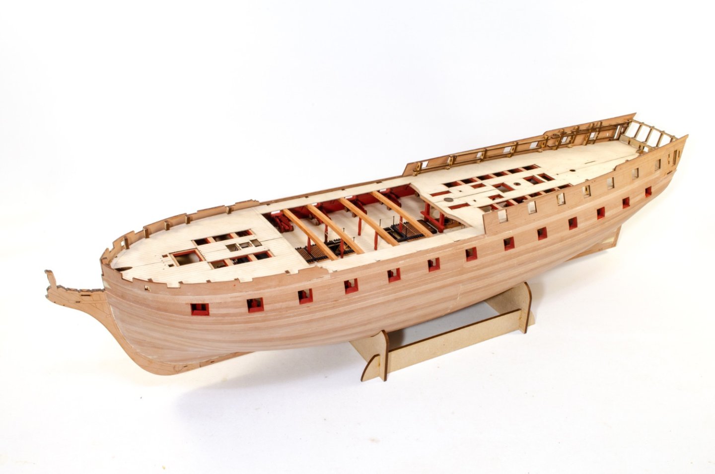
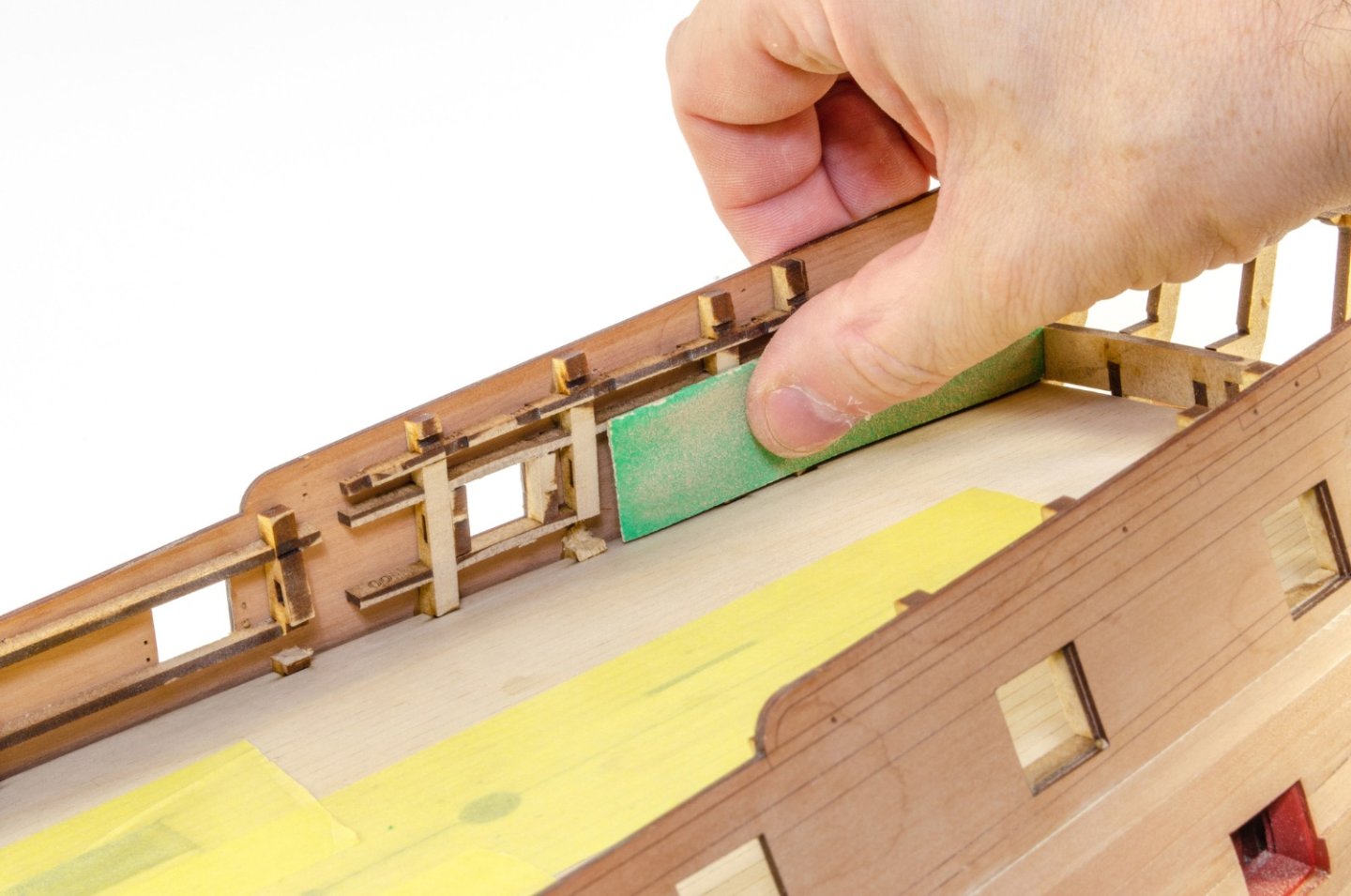
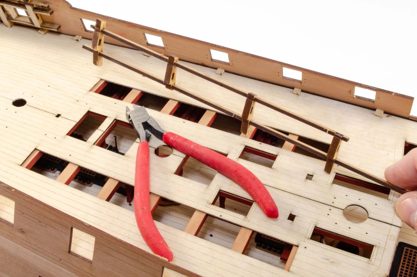
Ok, just an interim update. I was going to leave this until weekend when the office was installed, but I may as well show the upper deck being fitted and prepped for further work. Indy will be supplied with deck planking material as standard. At the moment, this looks like it will be red alder, which is gorgeous. I have some here that I'll do a couple of stages showing how to present it, assuming the modeller will have a good idea already. Indefatigable isn't marketed at modellers who are novices or intermediate. This is an 'Advanced' level kit in VM's new 5-point kit categorisation. More on that when it's released. What you see here are the standard ply sections which are laser-engraved so you have something as a planking guide. This is where checking the lay of the deck beams really does pay off. This deck is fitted in halves, unlike the main deck, simply as it's a more complex item. With everything test fitted and dry run several times, the deck beams have glue added to them and the deck is slotted into the outer bulkhead ears. Weights and clamps are then used to hold things down until dry. The 2 inch clamps are perfect for this, especially the cutouts where the front end clamps the joint and the clamp tail holds down the opposite side. And then the other deck half is fitted in the same way. There is a little more internal fairing to do, but this is easy enough. This is where the cabin walls will be installed and I need to make sure there's no bumps anywhere. And while this seems drastic, these frames DO need to now be removed as the next build stages will incorporate engraved inner bulwarks which glue onto the the sides. The forecastle bulkhead ears are now history too. More at weekend when I have the painted furniture in hand.


- 488 replies
-
- 35
-
-
- Indefatigable
- Vanguard Models
- (and 1 more)
-
Nope! This is why I farm this stuff out as he knows what he's doing, plus I'm still busy with woodwork 😆
- 488 replies
-
- 6
-
-
- Indefatigable
- Vanguard Models
- (and 1 more)
-
A guide to using MSW
James H replied to James H's topic in Using the MSW forum - **NO MODELING CONTENT IN THIS SUB-FORUM**
Have you tried another browser etc? The only solution I have to this sort of problem is to clear cache and cookies and try a different browser to see if can work. It's very difficult to provide solutions to IT when it's not at our side. -
A guide to using MSW
James H replied to James H's topic in Using the MSW forum - **NO MODELING CONTENT IN THIS SUB-FORUM**
Hi Joe, This is at your end. Shut down MSW, clear cache and cookies and then come back to MSW and login again. See how that goes. -
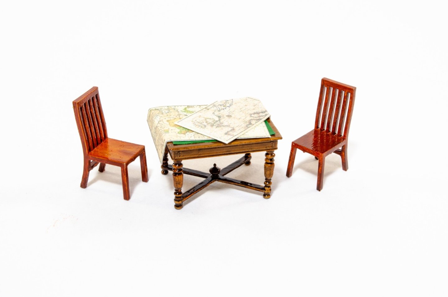
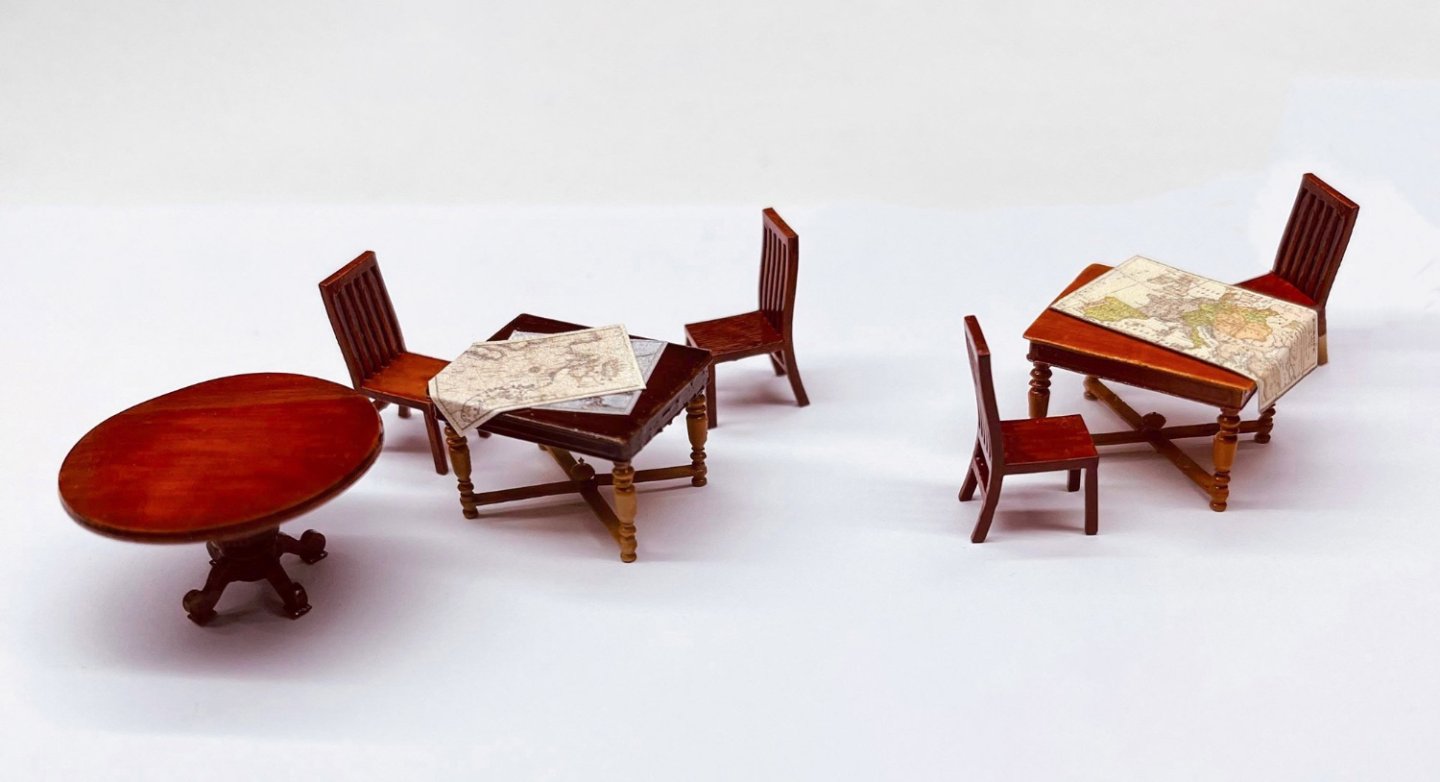
A very brief update before the weekend one. The office furniture has been painted by a friend of mine, and here it is. The round table will not be included with Indy, but the other table will, along with a couple of chairs. Here you can see a couple of incarnations of the furniture, 3D-printed and painted with oils. My friend also added the navigation charts for some extra effect! These items, including the round table are available already though. https://vanguardmodels.co.uk/product/cabin-furniture/
- 488 replies
-
- 46
-
-
-
- Indefatigable
- Vanguard Models
- (and 1 more)
-
Looking forward to seeing this. Remember to check out the notes I added about the position of the lower stern counter. Check step 149 for info.