

James H
-
Posts
5,624 -
Joined
-
Last visited
Content Type
Profiles
Forums
Gallery
Events
Posts posted by James H
-
-
Welcome to MSW!
Whereabouts in Scotland are you? Part of my family came from Midlothian (Bonnyrigg).
- Old Collingwood and mtaylor
-
 2
2
-
8 hours ago, popeye the sailor said:
either way, your going to have to scroll......so what's the difference? excellent looking kit........big change from depending on cement. how much does the kit go for?
-
4 hours ago, popeye the sailor said:
this is so cool James........I had a look at the site earlier this evening. I didn't see a price list though.......this must be a part work kit.
It is monthly. https://www.agoramodels.com/terminator-t-800/#buy-now
-
You're coming along with that nicely and quite quickly.
A tip for sanding the hull:
Use the pear sheet which had the bow pattern parts, and use the empty shape to cut some broad masking tape to the correct curvature and apply to the bow patterns. When you sand the bow, you can then protect the engraving on those areas.
- Glenn-UK and chris watton
-
1
-
 1
1
-
5 minutes ago, Egilman said:
An excellent set of online directions my friend, one suggestion, break it up into smaller parcels to reduce the scrolling, that would make it much easier to read.....
Beautiful work....
You're right! I will do that for future instalments. I just copied/pasted these from their original source.
- Canute, popeye the sailor, mtaylor and 2 others
-
5
-
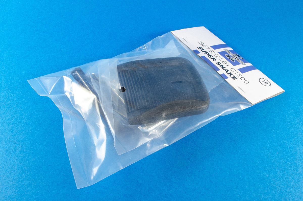
Pack 10
Well, we are definitely creeping close to the finish line after this package, and this one comes in a reasonably large and heavy box due the inclusion of the fenders. As she sits now, this is one imposing model. Agora have left a teaser too with the fenders not being fitted during Pack 10, but presumably waiting for next month until we can see things coming together for the exterior. And with this pack...we have wiring! Not sure what battery this will use though.
STAGE 74: DISTRIBUTOR, SPARK PLUG WIRE AND OIL PAN


The ignition coil is built from three parts which just push fit together. No glue needed here at all. The same goes for mounting it to the engine, and it will only fit one way too.


Plumbing the engine issues quite therapeutic and the suggested sequence of plumbing works well too. The vinyl hose needs to be cut to different lengths before being connected between the distributor and the main body. Everything is nicely colour coded in the instructions, so it's very hard to get wrong. I did use a little spot of CA between the hose/wire and the spark plug connectors as they did come off fairly easy. The oil pan was also fitted, though in hindsight, it would have been easier fitting that before the spark lines.


The beast can now be mounted into the chassis. For this, there's only two screws, but as the engine compartment builds up, everything becomes real sturdy.

STAGE 75: SIDE PANEL AND FRONT RIGHT SHOCK ABSORBER


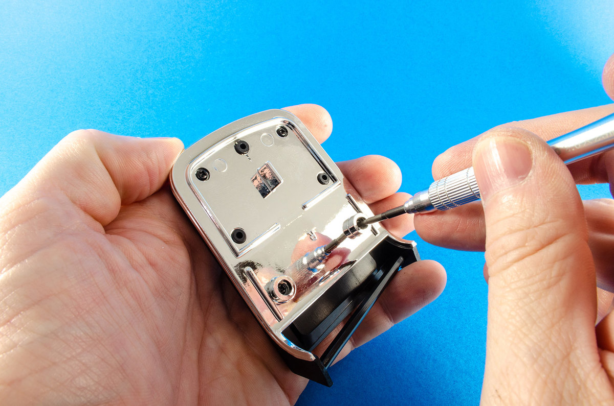
The right hand shock absorber piston is fastened to the car by means of another serrated pin. The radiator is now fastened to the side panel, and the piston body itself now screws to the outside of the right side panel. Onto the latter slides the shock absorber spring and then the whole unit is carefully lowered into position so the piston fits to the piston body. A little tricky, but not too difficult. Two screws hold the side panel securely in place.


STAGE 76: ENGINE CENTRAL PANEL, PUMP AND BRAKE FLUID RESERVOIR


This one is dead simple. The brake fluid reservoir is push fitted to the support snd the completed assembly screwed to the right hand engine bay wall. Care is needed not to trap any cabling under this wall, and the side screws mean you'll need to manipulate some of the surrounding parts to be able to get a clear shot.


STAGE 77: FRONT LEFT PANEL, SPEAKER AND SUSPENSION


It's now the turn of the left hand engine bay wall too be fitted. This is done in the same way as the first except the speaker needs to be fitted first and the retainer/support screwed into place to trap it. Care needs to be taken to ensure the wires flow from the recess properly.


STAGE 78: BATTERY, STRUT BAR, WATER PUMP AND PIPES


Almost everything in this pack is a push fit. The handle is first attached to the battery with the only screws to be used here. This needs to be a sold fit as the battery lifts out to reveal the actual battery pack for the car's electronics.

The oil filter can now be built and plumbed in, as well as the strut bar being attached. This makes everything quite rigid.


STAGE 79: WASHER FLUID RESERVOIR, ELECTRONIC CIRCUIT AND WIRING


It seems ages ago since we looked at any electronics, but here I get to plug the supplied cables into the circuit board. These are all numbered both on board and cable with only one board socket remaining free (06), which accommodates the speaker we recently fitted.

The board is now screwed into position as seen and the cables fed through various channels. I started with the cable the furthest away from the channel as I didn't want to end up with a rat's nest of untidy wiring. Cables 01, 02, 03, 04, and 05 are now connected to the various sockets that run from the battery box, steering column, lights, pedal etc. The speaker is also plugged into socket 06 on the circuit board.The windscreen washer fluid bag is also pushed into place next to the oil filter.

STAGE 80: LEFT FRONT FENDER STAGE 81: CHASSIS FRONT PANEL STAGE 82: RIGHT FRONT FENDER


Not too much to write about here except both fenders are now screwed to chassis front panel after the hood supports are fitted.


Until Pack 11, that's it!
- Canute, Jack12477, Ryland Craze and 8 others
-
11
-
Pack 9
STAGE 65: FIRST PARTS OF THE RADIATOR


This one's quite simple. The grille sits on the radiator and is trapped by he fan bracket which is fastened with a screw from the rear.


STAGE 66: RADIATOR SHROUD AND FAN BLADE


Construction of the radiator continues with the front panel (shroud) being fitted to the part I just assembled. Four screws fasten this from the rear. For the time being, the fan is set aside.


STAGE 67: FRONT OF THE RADIATOR


First, the radiator cap is screwed to the radiator top...


...and then the top os sandwiched between the new radiator front and the assembly already built. These just click together tightly and need no screws or glue.

The next grille is then secured to the front radiator panel.

STAGE 68: ENGINE PARTS


The first thing to go here is to curl the photo-etch air cooler grill around the inside lip of the air filter base. There is a red stripe on the mesh and this needs to be outwards and sat in the base. You'll still see a little of this when assembled. This task is quite easy to do and you don't need to curve the mesh beforehand.

The air filter top is now added and screwed into position.


The carburettor is now screwed to the underside of the air filter, and the complete assembly then screwed to the cylinder head cover.


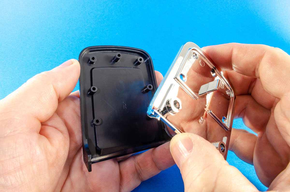
The beautiful, chrome finished valve covers are now screwed into position. These are marked 'L' and 'R' and are notched so they fit the right war around.

STAGE 69: FRONT HOUSING AND PRESSURE PUMP


The housing support is screwed to the engine's front housing.
 \
\
The pressure pump is now pushed on its support. No glue needed.

The two assemblies are then screwed together.

STAGE 70: ALTERNATOR, PULLEYS AND RADIATOR HOSE


First up is to push the alternator onto its support. Again, this is a friction fit, so no glue needed.

The radiator hose parts are also just squeezed together.

A single screw fastens the alternator support to the engine front.


No glue is needed for fitting the pulleys either. The fit is very good and really won't come off!

The radiator hose is then pushed into the radiator unit.

STAGE 71: ENGINE BLOCK, RIGHT EXHAUST MANIFOLD AND LIGHT SWITCH


Some heavy metal work again as the gas filter is screwed to the engine right half.

Over to the car interior for a moment. The light switch is fastened as shown, with a small clip holding it in situ. This appears to hold it very well.

Assembling the manifolds is very easy. These are just a push fit and each is numbered. The manifold connector is also printed with the number locations and they can only fit in one way.

STAGE 72: LEFT ENGINE BLOCK, EXHAUST MANIFOLD, GEAR BOX AND RADIATOR SUPPORT


Fitting the engine front to the left engine block was a little problematic as the plastic part on the rear of the engine front, wouldn't push full home. I used a small file to open up the slots on both the engine block sides, and that fixed the problem.

Whoops, note I added the curved gear box part the wrong war round? That was changed after these photos were taken.

Both manifolds are now clipped into the engine block.

Another push fit sees the radiator support bracket fitted to the completed radiator unit.

STAGE 73: ENGINE BLOCK BOTTOM, OIL COOLER AND CONNECTION CABLE


The large chunk of metal and its assemblies that built up the upper engine, is now slotted into the engine housing and the engine bottom plate screwed into place.


Filler pipe, pressure probe and connection cable are now added.


The oil cooler is now assembled and fastened to the radiator unit.


More next time!
-
Pack 8
STAGE 56: SHOCK ABSORBER AND LEFT REAR BRAKE


The shock absorber cylinder and mounting plate need to be fitted together. A small steel pin is supplied for this and this is pushed into the assemblies as shown. The serrated end grips the plastic and holds everything together tightly.

The assembly fits to the left side of the car on the underside as you can see here, and fastened via a screw on the reverse. You also need to remove the shock absorber sprint plate so you can fasten the piston to the underside. This is then replaced, fitting the piston into the cylinder body. The instructions show the left rear brake pushed into position, but as this will just drop off until the wheel is fitted, I kept this to one side.


STAGE 57: LEFT REAR WHEEL

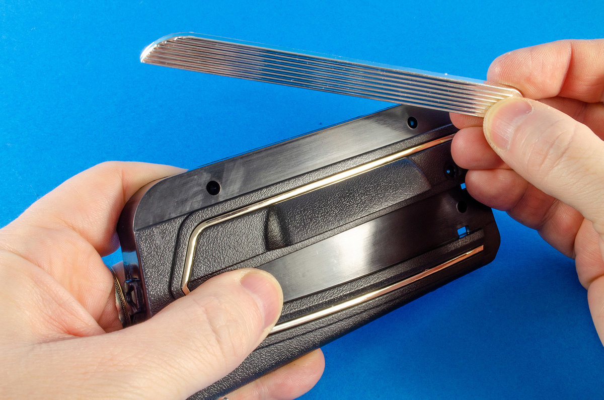
Now, about that wheel! This is assembled in the same way as the previous two, leaving the rubber tyre in hot water for 5 minutes to soften it enough to fit the rim. The brake then slides onto the wheel and signed with the slot. The wheel is then fitted in place with a screw and the Shelby cap used to hide the screw.


STAGE 58: SHOCK ABSORBER AND REAR RIGHT BRAKE & STAGE 59: RIGHT REAR WHEEL

These are simply repeats of the previous stages 56 and 57, but for the right side rear wheel.
STAGE 60: EXHAUST SYSTEM ASSEMBLY

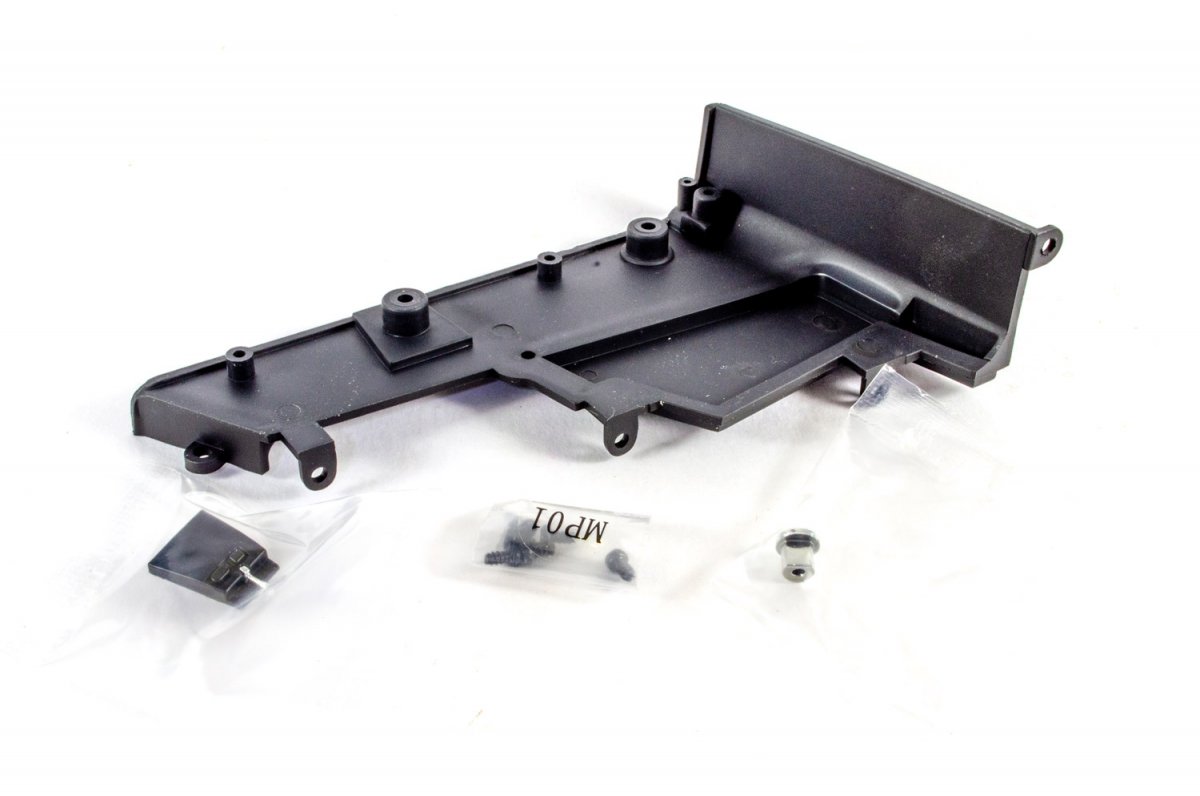
Before you can do anything with this stage, you need to remove this floor pan section. Care is needed not to mix the screws up as there are three different types here, but two of those types are for the channel, so it's pretty easy to sort. An upwards twist helps remove the part.

The previous exhaust assembly can now be screwed into position as shown here with the chromed exhausts protruding from the rear. This fastens with 6 screws and you really can't make a mistake here.

Next, the resonator pipe halves are screwed to the exhaust system, and the completed assembly then fitted to the chassis, followed by replacing the floor pan section.


STAGE 61: STEERING COLUMN AND STEERING WHEEL


First, the pinion pushes onto the steering column. Both of these parts are metal.

The microswitch is now added. I used a spot of CA on the underside as the subsequent assembly showed this pop out of position. Easy fix.


In my case, I had to later repeatedly fit and remove the assembly as it appeared the steering column was a tad overlong. This meant that I couldn't push the pinion down into the chassis far enough without the steering column pushing the wheel away from the housing and microswitch. To fix this, I filed away the bottom of the pinion that wasn't serrated, and also took 1mm off the top of the column where it entered the steering wheel. The whole lot now works great when fitted to the model.


STAGE 62: TRUNK PANEL

Nothing to see or do here, so move along!
STAGE 63: SPARE WHEEL, STEERING WHEEL AND FLOOR ASSEMBLY

This wheel is assembled as the others and will be the spare that is kept in the boot.

The steering wheel can now be fitted to your model, although I think this is best done when the interior is bolted to the chassis because there's less chance of damaging it, and also more chance of getting everything aligned properly.


The interior is now fitted to the chassis...

...and here you see the cap which pushed into place to hold the pinion down onto the rack.

STAGE 64: TRUNK PANELS, JACK, AND FIXING THE SPARE WHEEL


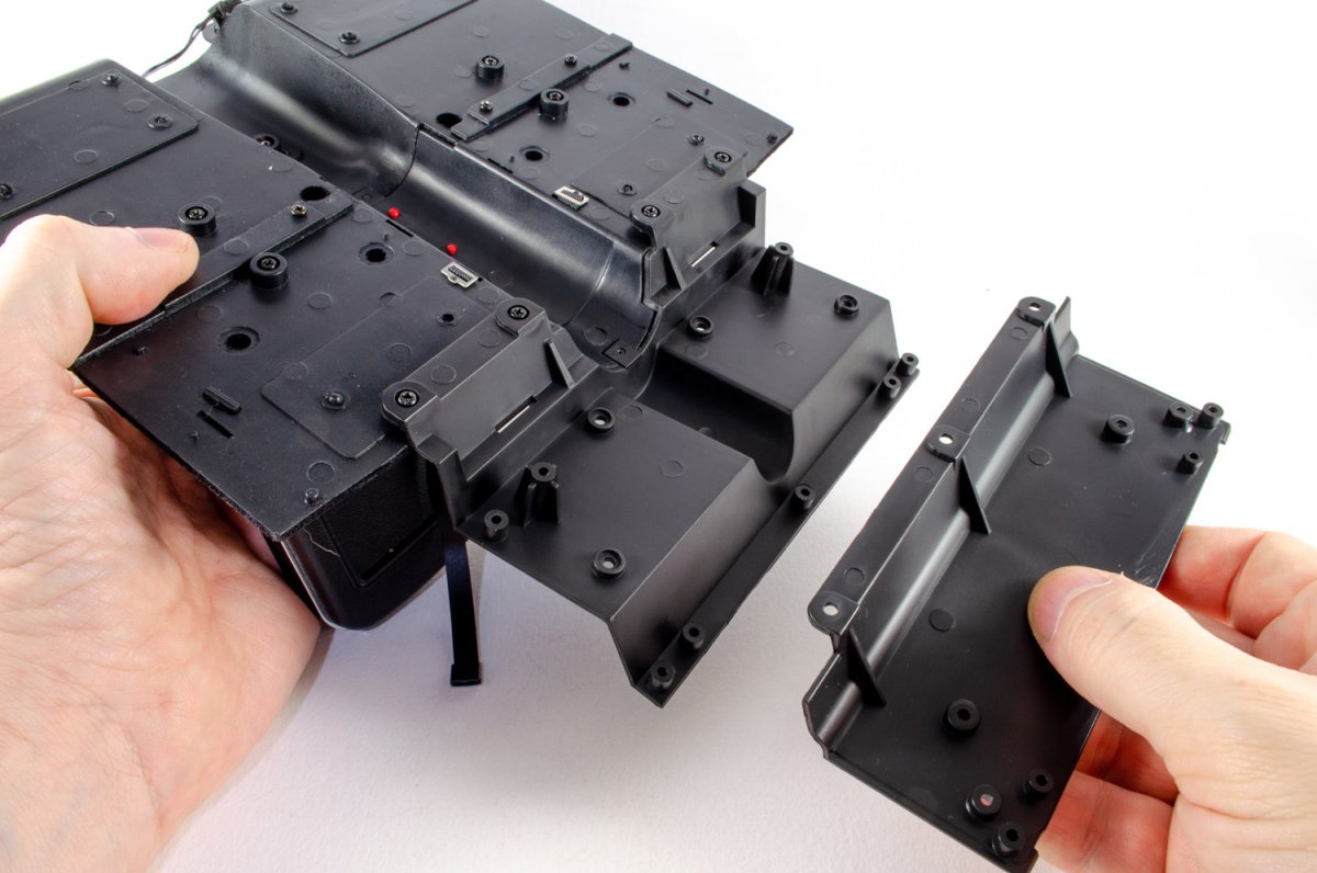
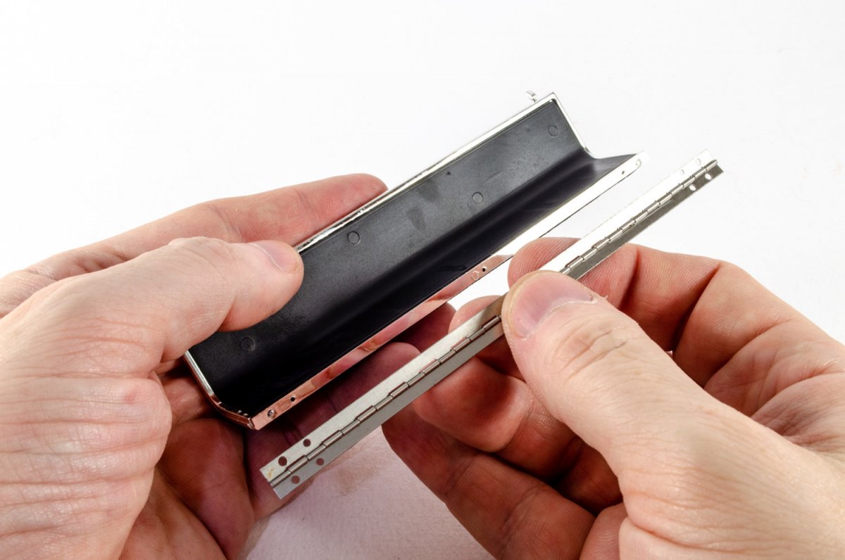
Using the panel we got earlier, the side plates are now fitted to it by clip connections. The assembly is now fitted to the car.


The spare wheel is now made up with the mechanism to lock it into position.


Finally, the wheel is fitted.

I'll post Pack 9 tomorrow to get myself up to date.
- GrandpaPhil, Ryland Craze, Canute and 4 others
-
7
-
Are we really already on Pack 7? 😲
Ok, there's some repetition in this with the previous pack, so I'll not repeat lots of photos of the same, but there's still plenty I've had to edit for this update.
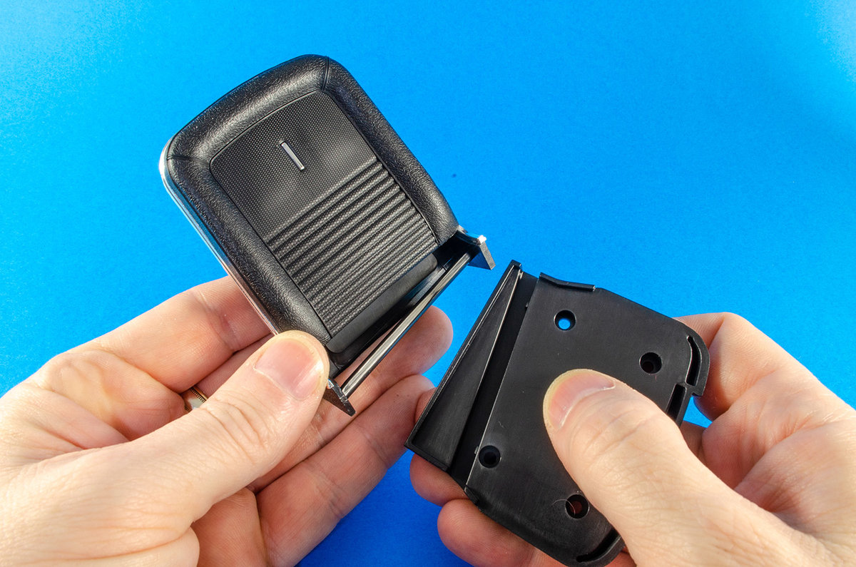
STAGE 47: RIGHT REAR INTERIOR PANEL: Decorative Accessory and Rear Seat Release Lever

This is simply a reproduction of the left hand rear interior panel.


I didn't fasten in the folding seat part at this stage as I didn't want to mark its surface as I progressed. This was fitted right at the very end.
STAGE 48: LEFT REAR UPPER INTERIOR PANEL AND VENTILATION GRILLE

A little more repetition here as left rear upper interior panel mirrors the one we built in the previous pack.


STAGE 49: LOWER DASHBOARD PANEL, ROLL BAR AND SEAT BELTS


Ok, onto some nice interior detail stuff now. The first thing to do is to install the lower dashboard panel. The instructions say you can unscrew the dashboard to fit this but I didn't feel that was necessary. It was very easy to fit with a screwdriver with a long shank.

The seatbelts are also very simple. These need to be slotted into the retractor units so that the textured surface of the belt is seen pointing forwards. Once slid into the retractors, the clip is bent over and locks into the unit. That's quite clever. No glue needed. The units are then screwed to the roll bar and the whole unit fastened to the car interior.


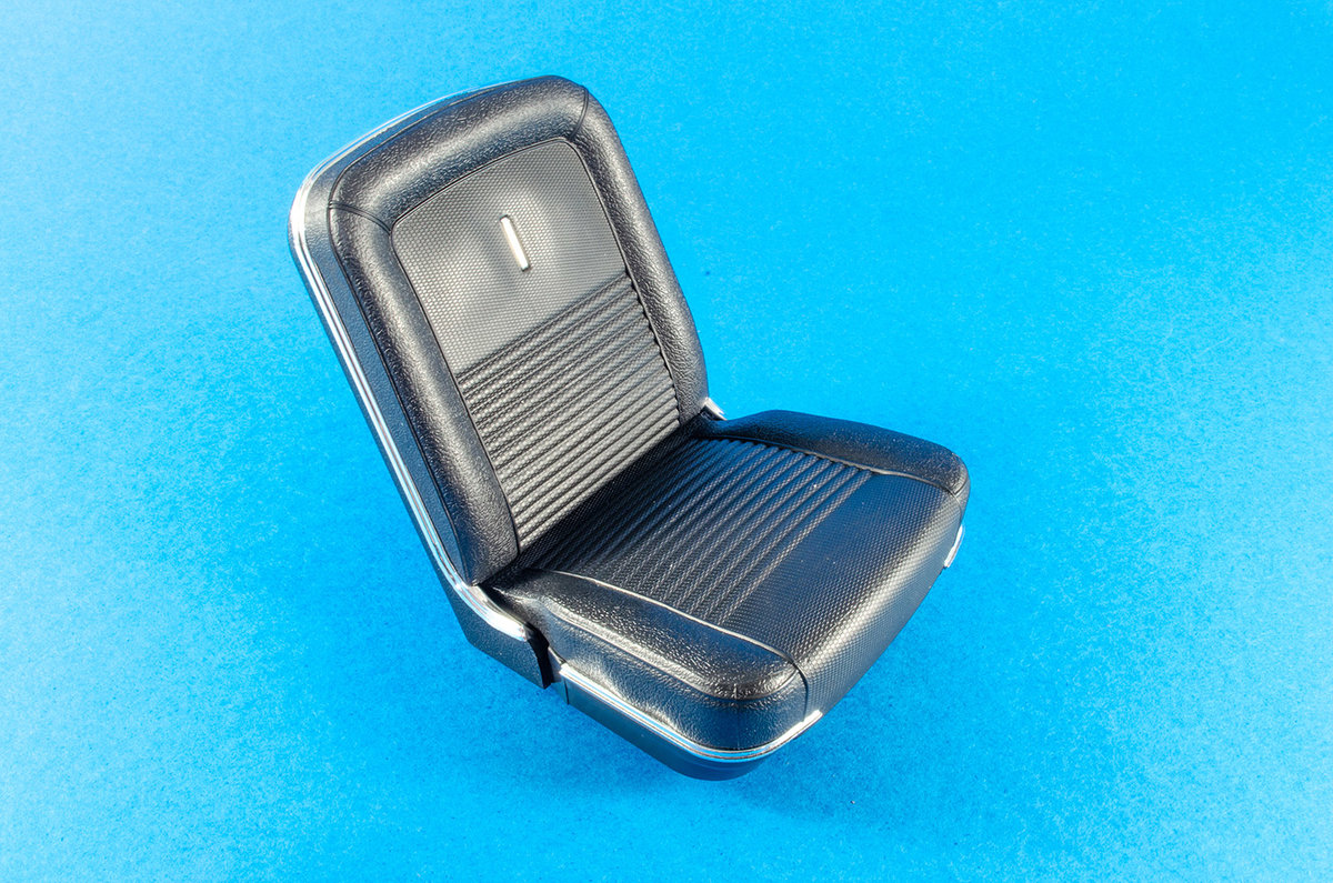
STAGE 50: REAR SEAT AND SEAT BELTS


Now we can build and install the rear seat. The unit is actually moulded as a single piece, but the seatbelts must be fitted, making sure that the textured surface faces upwards. For a little insurance, I used a spot of CA on the underside where they connect to the moulded pin.


The seat is now fitted to the interior with four screws.


STAGE 51: REAR PLATFORM AND SEAT-BACK LOCKS


The rear platform consists of two main parts where simply push together, making sure the holes in two top corners are aligned. This unit is then screwed into the interior and the seat locks pushed through the holes and also secured with screws from underneath.


Got to say that I'm finding this interior real impressive at this stage!

STAGE 52: LEFT FRONT WHEEL: Tire, Rim, Brake disc, Wheel hub, Brake Caliper and Hubcap


Now I can look at something else other than the interior, which I suspect is almost complete apart from steering wheel etc. Time for a different wheel. To fit the rim to the tyre, you really do need to soften the rubber. You'll not fit this unless you have superhuman strength, without leaving the tyre in freshly boiled water for 5 mins. After that, it goes together real quickly.

Now the brake disc and calliper can be assembled.


Note the slot and peg on these parts and put them together. A quick spin of the brake disc unit will soon locate properly to the rim. A single screw is then used to fasten them together before the Shelby logo badge is pushed into place over the screw hole.


STAGE 53: RIGHT FRONT TIRE AND RIM


Again, freshly boiled water is used to soften the rubber before the rim is fitted.

STAGE 54: MUFFLER AND EXHAUST PIPES


A slight diversion with this pack as I build the muffler. Note that I don't fully screw the body of this together as the various pipes need to be interred and locked into the ends of it. When in position, the body is tightened up and the chrome exhaust tips fitted with. spot of CA.


STAGE 55: RIGHT FRONT WHEEL PARTS: Brake disc, Wheel hub, Brake Caliper and Hubcap


You get the idea with this. We are repeating what we did with the left wheel. Just make sure you don't get these mixed up. The right front wheel is now fitted to the tie rod. I found I needed to drill the hole on the calliper as the screw would barely go in there.

The left wheel is now fitted and again, I drilled out the wheel hole to allow the screw to properly fit.

The completed unit is fastened to the chassis so that the ratchet on the tie sits within the mechanism that was fitted when the chassis was built. This makes a ratchet sound when turning the wheels.

More next time!
-
STAGE 39: INTERIOR DETAILS
Front and Rear Floor Mats and Fire Extinguisher

With this new pack, Agora is sticking with working on the interior, and there's detail work as well as the various panels. This first set of parts contains the rubber floor mats and fire extinguisher. The floor mats just push into the holes in the floor. One thing I did need to do was to remove a little of the fibre from the holes, as it was stopping the mat pins pushing fully home. A scalpel was used to clear the holes and the mats pushed firmly in, clicking as they locked into position.


Remember those seats? Those are now fitted to the interior. Note the 'R' and 'L' on the underside and fit them in the appropriate place as shown on the instructions. Two screws hold each in position.


The fire extinguisher is now assembled. The handle is pushed into the lower half as shown here, and then the upper half locks everything into position. A sticker is then carefully applied and the finished extinguisher plugged into place between both seats.


Looking very, very cool!

STAGE 40: REAR SEAT SUPPORT


From here, the interior starts to take on a real life and shape of its own. There's only one part in this pack, and this is screwed into position with four screws. You also have to make sure that the tab in the tunnel area is clicked firmly into position as it was with an earlier interior stage.


STAGE 41: INTERIOR REAR PLATFORM


Another pack with just a single part, and this extends the interior even further back. Just three screws hold this in position.


STAGE 42: LEFT REAR INTERIOR PANEL,
Interior panel, Decorative Accessory and Rear Seat Release Lever

I'm actually very pleased that the side panels are now being fitted as it gives some rigidity to the interior. A 'decorative accessory 🤣' and rear seat release lever are screwed into position on the left interior panel.


The panel is now screwed into position on the left hand side of the interior. Note that there is a pin locating position on the underside too, which keeps that connection rigid.


STAGE 43: LEFT REAR UPPER INTERIOR PANEL AND VENTILATION GRILLE


More work on the left hand side now with the upper left interior panel. The ventilation grille is pushed into position and then screwed from the rear. I needed to remove a little plastic flash from the edges of this, which neatened the whole part up.


This panel is now fitted above the previous one with just two screws. This will be made far more rigid very shortly.


STAGE 44: INTERIOR TRUNK PARTITION PANEL


This single part is pretty obvious. It's the interior truck partition panel, and is held to the interior by three screws on the underside. It also secures to the upper left panel with a plug pin fit. I found it easier to push those in first and THEN fit the screws.


STAGE 45: REAR SEAT FOLDING PANEL AND HINGE


We now see some very tiny screws here, almost like those in a jeweller's box. First, the hinge is located as shown, and then three of those tiny screws are used to secure it to the rear seat folding panel.......


STAGE 46: REAR SEAT BACKREST PANEL


.....then we are onto the next pack of parts! Take the rear seat back, and rear seat back panel, and carefully push them together.


Now screw the other edge of the single to the assembly.

And, er......that's it for another month! Got to say I'm loving this build!!
- Canute, GrandpaPhil, Egilman and 3 others
-
6
-
Pack 5 landed on the doormat late last week, so spent some time on this one. Please excuse some of the interior photos as the velvety interior is quite hard to photo on a white background without highlighting dust etc. The finish itself looks excellent, so I hope I've done it some justice here.
STAGE 31: STABILIZER BAR AND LOWER SUSPENSION ARMS

This pack is very simple and just adds the stabiliser bar and suspension arms in a single piece. This needs to be able to pivot and flex to is can take the natural suspension of what will be a very heavy model when completed. The stabiliser bar is first screwed into the forward chassis, and then pins used to locate the suspension arms. The pin is serrated and grips the metal of the chassis. I fitted the stabiliser bar first, unlike the instructions said, as this seemed the most natural thing to do.


Be careful with the pliers so you don't damage any of the metal paintwork.

STAGE 32: UPPER SUSPENSION ARMS

More pins to use here as the suspension arms and supports are assembled. I also found the screws a little tight in the metal, so I first put these into the chassis as far as I could get them, then removed them before using them to fit the suspension arms.


STAGE 33: FRONT INTERIOR FLOOR AND GEAR LEVER

And now for something completely different! Some interior!
The interior parts of this model have a black velvet-style finish to them, and you'll need to be careful that you don't mark this as you build. I found a piece of de-tacked masking tape was perfect was removing lint and hairs/dust etc. This pack is simple.....we just screw the gearstick to the interior floor by inserting a screw from underneath. Et voila!

STAGE 34: FRONT SIDE WALLS, PEDALS AND SWITCHES

We now see the first of the electronic parts in the form of two microswitches for the accelerator and brake pedals. First though, we fit the front side walls, being careful not to damage that velvet interior finish on them.


The switches are now located to the switch holder, observing the correct position for each 01, 02.

The switch holder is then clicked to the rear of the interior and screwed into place.


The pedals are now fitted. I had to make sure the pedal plungers went through the holes in the interior and could make contact with the switches. One of these was a little sticky, so repeated operation freed it up so it worked perfectly.

STAGE 35: DASHBOARD AND FUSE COVER

Another dead simple one. The dashboard and fuse cover are now put together. a single screw from the reverse of the dashboard is driven fully home.


STAGE 36: DASHBOARD TRIM, DIALS AND SHELBY BADGE

We can now pretty-up the dashboard area. The first thing to do is apply the self-adhesive stickers for the dials. These are clearly identified for location. these are then peeled from the sheet and applied with some tweezers so I get the correct orientation.

The glass dial covers are then clicked into position on the rear of the dashboard trim. The cloth that came with the kit is then used to remove any fingerprints before the trim is sat in position.


The dashboard strip with its satin finish is now sat over the chrome trim and screwed into position from behind, locking the metallic parts in place.


The Shelby badge now has its sticker applied and is screwed to the dash from behind.

STAGE 37: CENTRAL DIALS, CAR RADIO AND GLOVE COMPARTMENT

Great to see more interior parts so we can work on the dash. I have to say it's looking pretty darn nice. First up, it's the radio that we need to fit....from the days when you did have to actually tune them in!


The central dials are now assembled. Firstly, the stickers are added as before, and the dial glass located. I needed to trim a little clear plastic to make this sit flush, and then the frames could be added. The unit was then screwed into position under the radio.


Two parts are supplied for the glove box. The interior is screwed into position and then the door is clicked into place from the front. This will open/close.


Very excited to see the dash unit could now be fitted to the interior. Two screws holds these large units permanently in position.


STAGE 38: REAR FLOOR AND FRONT SEAT BELTS

More care is needed here as we have another velvet finish part in the shape of the rear floor. Before we do anything else, the seatbelt anchors are clicked into place in the slots on the floor section. These are quite a tight fit and I needed to remove fingerprints with some de-tacked masking tape on the black surface, when done.

The rear floor is now screwed to the interior section and a central pin used to lock the 'tunnel' together.

The seatbelts are slotted into position as shown, making sure that the Cobra badge is facing upwards on the clasp.

Flip the model over and located the belt to the pips as shown. I needed to use. small spot of CA to make these stay in position.

AND.....we now have this!

Looking forward to Pack 6!
-
Pack 4 dropped onto the doormat this week, as the postman legged it quickly in case I gave him coronavirus 😆
Well, I had to make a start, so here we are!
Stage 23: Middle Chassis
A very simple, single piece packet with some screws, but this really starts to make that chassis grow! This simply bolts to the rear chassis that we just saw in my last post.


Stage 24: Front Floor Pan
Again, another simple, one-part pack, and this one fills in that gaping hole in the middle chassis and extends the channel for the driveshaft. What I like about these parts is how precisely they fit...no faffing or manipulation. Just how it should be.


Stage 25: Driveshaft
We can now build that driveshaft and install it. I suppose this is where you'll find if you got the differential cover the right way around 😆. Take the two halves and pop them together. They'll only fit one was as the ends aren't symmetrical. The small MP02 screws are what are used to secure them. Once tightened up (not over-tight!), flip the chassis upside down and slot the tabbed end into the differential, with the two protruding lugs pointing towards the chassis, and then turn the assembly around. Using the other screws, secure the driveshaft securely in place.


Stage 26: Gearbox and Crossmember
Silly me forgot to add the crossmember into the components photo, but you still see me install it. Take the blue gearbox unit and position it as shown. It will only fit one way, so there's no chance of getting it wrong. Flip the chassis over again and secure into position with two screws. Now add the crossmember and again, secure with two screws.


Stage 27: Front Chassis
Another single-part stage, but this now extends the chassis into the full length of the GT500, and it's certainly an impressive beast! This is chunky and heavy metal part too. All that needs to be done is to locate it to the chassis section you already built and then bolt into position as shown.


Stage 28: Front Fender Splash Guards
Only two pieces here, and they do exactly what they say on the tin! I found that adding the screws first and then removing them was the best strategy as you can't get a lot of leverage on that screwdriver with the guards right up against it. Be careful handling the chassis now these are fitted as they could be a little fragile.


Stage 29: Steering Rods
We can now temporarily put the chassis down as the steering rods are assembled. Quite simply, these three components are bolted together using the MD06 screws. This should not be overtightened as it's a functioning part. I found the screws a little hard to drive in so needed a slightly larger screwdriver with a little more torque.


Stage 30: Steering and Suspension Components.
Whilst the steering rods were in hand, I took the Pitman Arm and bolted this to the assembly I just built. Again, I needed a larger screwdriver to overcome the difficulty I had fitting these together.The suspension arm mounts are then secured to the underside of the chassis via two screws. These are socketed so they won't wobble around.
Lastly, the steering gear is also screwed into place. Careful with this as it's plastic and you don't want to strip the threads.


That's it until Pack 5!! For to say this is looking very impressive.

More next time 😘
- Egilman, Canute, popeye the sailor and 5 others
-
8
-
Ok, onto Pack 3! Let's change that background to white also, as I need to get a new blue sheet and lockdown prevents this!
This is a lovely pack goodies because we now get to work on the lower chassis and put together some large parts that give an impression of just how big this 1:8 beauty will be when complete. Quite a bit of work to do here too, and let's face it, many of us haven't much else to do with our time at the moment! 🤣
Stage 15: Rear Main Chassis Assembly
Not much in this packet, but it is pretty significant. Take the rear main chassis part and connect to the fuel tank assembly. As simple as that, but now you can see how this thing is starting to grow, and the fit is superb!


Stage 16: Rear Floor Pan
Again, only one part here, but I got 2 packs of screws. Only one of them is used, so the other looks like I can just use for any spares I might need (although the instructions also show the pack, but no use for them). Take the Rear Floor Pan part and fit to the rear chassis. Pretty obvious where this goes. It's simply like fitting a square peg to a square hole, metaphorically speaking. Nine screws hold this in place.


Stage 17: Lower Rear Axle
This pack gives us the differential housing cover and the lower rear axle, plus screws. Take the differential cover and fit two screws into it so they go fully home. This just nests to the outside of the axle. Note the orientation of the differential though. That's pretty crucial.


Stage 18: Upper Rear Axle
Carrying on from the previous stage, we now get to complete the rear axle using this pack of components. Again, check the orientation of the differential from the previous stage and then fit the upper rear axle. You can clearly see that orientation here. Secure the parts with screws. You can also slip the springs into position too.


The upper rear axle assembly can now be fitted to the rear chassis. Noting orientation, sit this so the two rods that the springs are sat on, connect to the lower chassis as thus, and then secure with two screws...


Stage 19: Left Rear Wheel Housing
Another pack with one part, but oh how beautifully it fits! Take the housing and secure to the left side of the lower chassis with three screws.


Stage 20: Left Leaf Spring
Now, you need to pay attention here to make sure you get the orientation of these vital parts, correct. You'll struggle to disassemble otherwise. These photos should clearly show you how this fits. Note the shape and position of the details on the leaf sprint itself, and be careful not to bend this part as it's a little pliable. Take the front shackle (very different to the rear shackle) and note which side of the leaf spring it fits to. Now push the pin into position to secure. One side of this is serrated, and when you push it fully in, those serrations will bite into the plastic and lock it. Use pliers for this.


Now do the same for the other side...

The leaf spring can now be fitted to the lower chassis. Note how those shackles match the underside when they fit. Lastly, the spring plate can be fitted with two screws.


Stages 21 and 22: Right Wheel Housing and Right Leaf Spring
The last two packs are the same as the previous two except we now fit these for the right hand side of the lower chassis.
And here's how it all looks when done! More next time!

-
Pack 2 arrived last week, so here we go with the next update.
There was a certain amount of repetition with this pack as we get to build the right-hand door and also the right seat, but it's all good clean fun, plus we get to see a large chunk of heavy metal that forms the rear chassis. Ok, here we go...
Stage 7: Right door assembly
As you can see, we are going to build the right-hand side door, giving us a matching pair! Good to get both of these so early in the build.

The handle is taken and pushed into the soles on the metal door panel. This only fits one way, so no problems here.

A single screw secures the handle from within the door panel.

Stage 8: Right window assembly
Be careful with the main clear part as there's no protective film on it. Keep it nice and clean with the supplied cloth too.

Locating the window to the door panel is a cinch. You really can't get this wrong.

With it in place, secure with three of the prescribed screws. Careful not to mark that window!

Now take the hinge and sit in the door slot in this orientation. Note the chamfer on the underside.

Now take the bracket and push into position over the two pins on the metal door panel. Please note again the chamfer on this part too,

A single screw locks everything nicely into place.

Et voila!

Stage 9: Right door trim
Our packet...

Take the lower trim strip and push into position on the lower side of the inside panel.

Secure with two of the correct screws.

Now take the interior door handle and the door handle bracket and sit together exactly like this.

Fit the assembly within the inside of the door panel. You'll need to carefully tuck the handle through the slot in the door. Two screws lock the parts into position.

A further screw stops the handle from waggling about.

Now the window crank handle is fitted. You'll note a small tab which assists orientation.

A small screw also holds this in situ.

Now we take the (almost) completed inside door panel and sit in position within the metal door panel itself. Simply alight the screw holes with the holes in the blank trim area of the inside panel.

Then finally secure the assemblies together.

Now it's the turn of the upper trim strip. You need to be careful getting this into position behind the window crank handle. Some careful manipulation is needed. When in place, push it into the interior panel to lock into place.

...and it looks like this.

Stage 10: Passenger's seat backrest.

Take the passenger's seat backrest and backrest frame and sit them together.

Fasten together with four of the prescribed screws.

Now take the soft-feel backrest upholstery and push it into position. The chrome plated tab will protrude through the slot in the upholstery.

There, dead simple!

Stage 11: Passenger's seat
You'll notice these stages are exactly the same as those from Pack 1.
Take the passenger's seat base (with the moulded channel) and sit the backrest into it..

...just like this. Now we can take the seat cushion and sit in place over the base.

Flip the seat over and screw tightly into position.

The finished seat looks like this, and also tilts forward.


Stage 12: Rear chassis
One large and heavy bag with a single, metal component. We'll need to crack open another packet to be able to use it...
Stage 13: Fuel tank bottom

The lower fuel tank pushes into place over the lips on the lower chassis...

...just like this. I think we'll need our last packet to finish this.

Stage 14: Fuel tank top and filler hose

Take the filler hose and sit within the hole on the fuel tank top. This will only go one way due a tab.

Firmly secure in place.

Now take the assembly and the lower chassis and fit them together, with the fuel tank filler hose pointing aft.

Firmly screw together.

C'est complet!

Until next time...
😁
- popeye the sailor, mtaylor, Egilman and 4 others
-
7
-
A driver needs somewhere to sit, and this is it. The backrest and backrest frame are now pushed together and secured with four screws.


Superglue is now dripped into the three holes in the unit. The instructions say to apply this to the pins, but it's safer to do it this way as the glue can't run anywhere and ruin the parts.

Push the soft plastic upholstery unit into the holes. The tab helps with alignment.

The driver's seat back part now locates to the base. You can easily see how these go together with the channel.


The driver's seat upholstery (with pre-fitted trim) now sits in place over this and is screwed together from underneath.


The finished unit looks like this and can also be tilted forward.


Pack 1 is now at completion and I hope to be able to bring Pack 2 to you fairly soon.
- mtaylor, GrandpaPhil, yvesvidal and 5 others
-
8
-
Care needs to be taken over the next stages because you really don't want to damage this beautifully clear part.

Screw the window unit into place within the door interior, using three screws.

Next, fit the hinge. Note the orientation of this as it's important.

Now fit the retaining plate with the bevel facing upwards. Secure with a screw.

We can now start building the door interior. Take the inside door panel and lower trim strip, and fasten in place with two screws.


The door handle bracket needs to be orientated in the correct way here. Take the interior door handle and fit it like this.

Now fasten the bracket into the back of the door panel, slotting the handle through the hole. Take another screw and screw this into the back of the handle. This will stop it from rocking about.

The window crank handle now fits into this recess. This is tabbed so it fits in the correct position. Screw this tightly from behind.


The interior door panel can now be fitted to the inside of the main door, and secured with two screws.


The upper trim strip now fits in place and hides the screw holes. This needs to be fitted carefully so as not to damage the door fittings.


- yvesvidal, GrandpaPhil, Egilman and 5 others
-
8
-
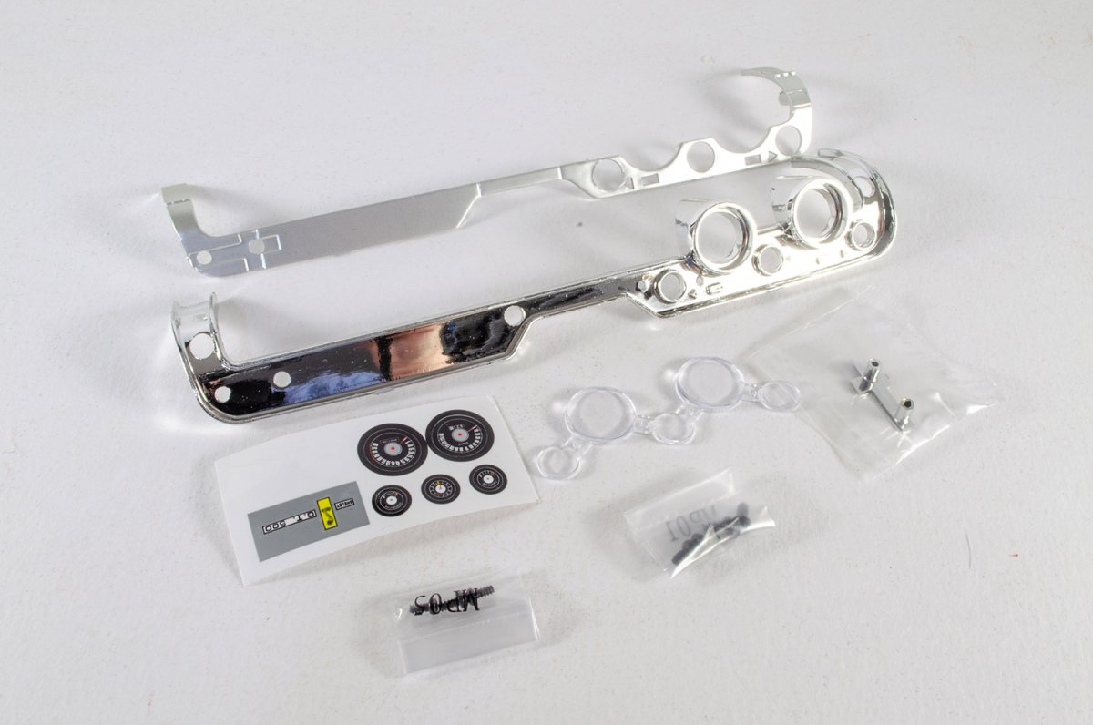
PACK 1
I've only recently started building 1:8 cars as part-works, and I have to say that this model is gorgeous. The parts are seriously high quality with everything fitting perfectly so far, and the paint finish is immaculate. Packaging is the same sort of thing you see with similar kits from DeAg, but this one comes in a real study box to protect those parts. The colour info sheet is excellent and the inclusion of a polishing cloth is a nice touch does help at the end of a session when you pop things away until the next pack....and especially for taking photos for a build log.
Things start nice and easy with the front fascia and bottom grille

The photo-etch grill is nice and sturdy and fits into the interior of the fascia, secured by a couple of screws. There is a little side-side movement so make sure the alignment looks even and then tighten up those screws.

Next up is the bumper. This fits with the pips on the upper side and the recess on the lower side. Pop this into place and secure with the supplied screws.


The headlight units are pre-made, and marked as 'L' and 'R' on the rear side. Take each in turn and slot into position from the front of the fascia.

Flip the fascia over and secure with screws. Make sure these are nice and tight.


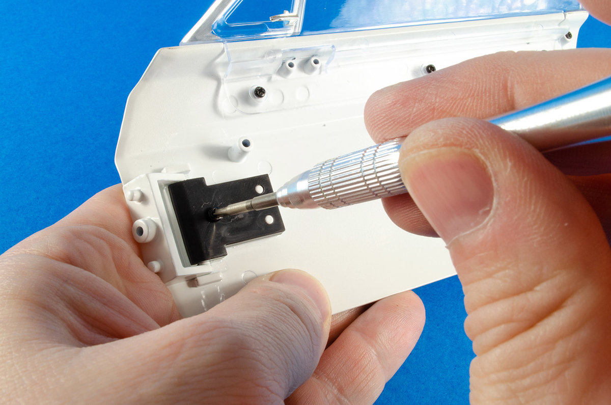
Now, it's the turn of the left hand door, also with its famous livery. We now need to fit the mirror unit.

The mirror unit has a tab which goes through the slot in the main door panel.

Two screws now secure this from within the door panel. This will pull it up nicely into place. Again, make sure it's tight, and careful not to scratch any paintwork.

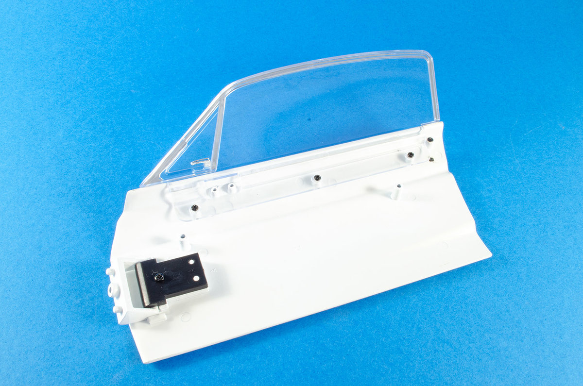
It's now the turn of the door handle. This can only fit into the exterior of the door in one way.

Again, from the interior, secure this with a single small screw.

And here is the result.

-
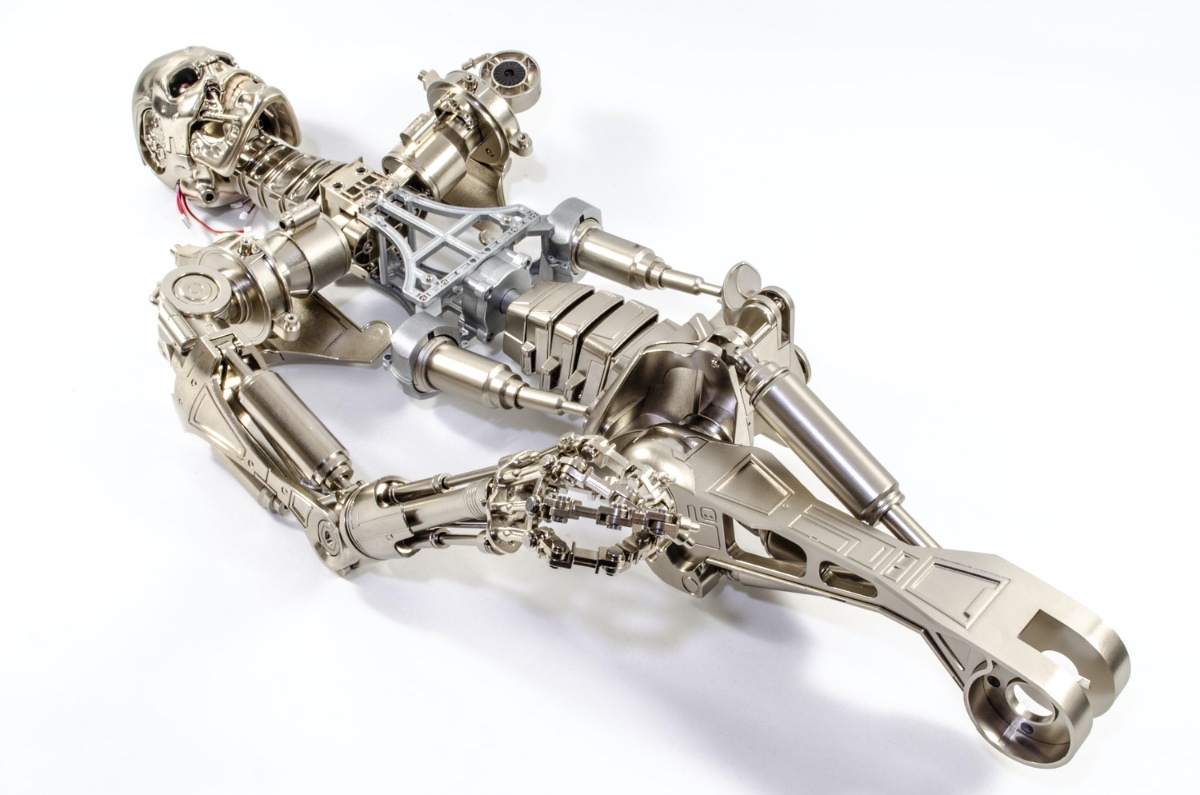
Are we really half way through this build already?
After last months disappearance of the camera memory card, I had to get a new one, so this build starts again from here with only the actual pelvis construction unaccounted for.
Pack 6
STAGE 51: FITTING DETAILS TO THE PELVIS

Hardly anything to do in this stage as all we are doing is plugging the front side of the pelvis into position and fitting a joint connector to the hip. The latter is fixed with some Loctite CA.. We do have a swivel part for the next stages though, so onwards...


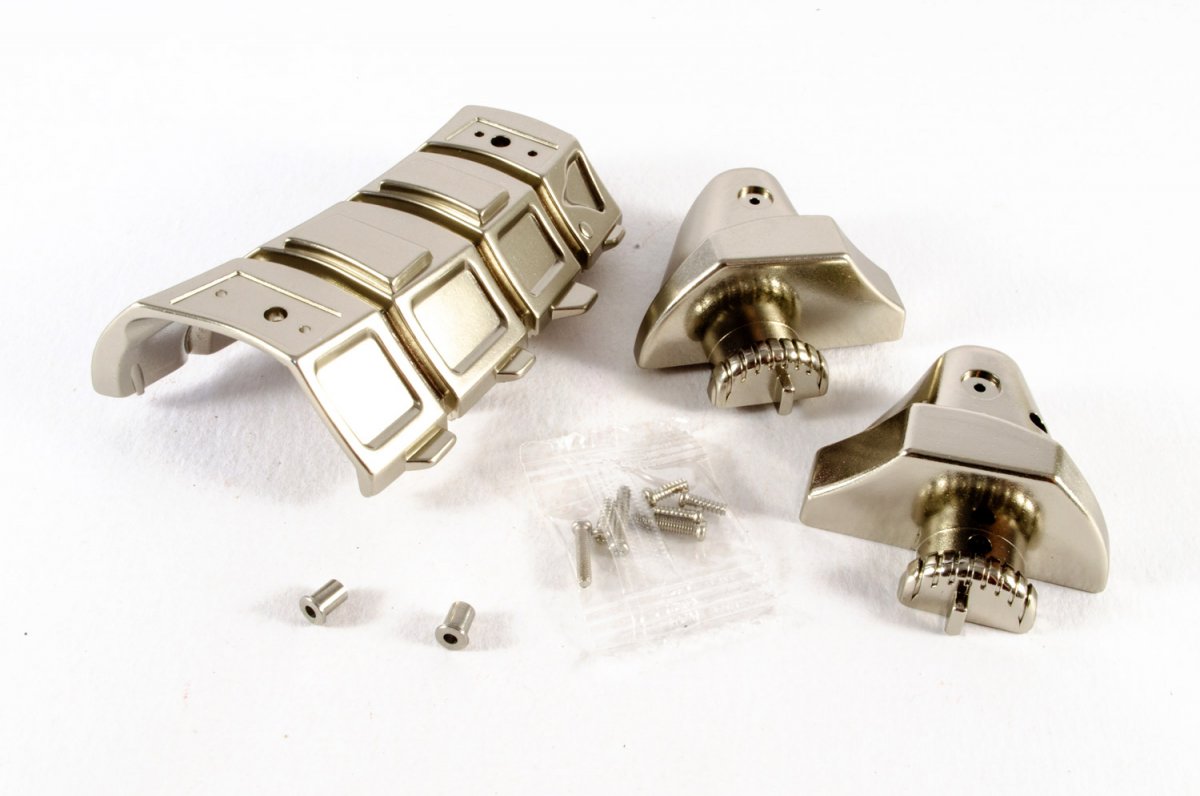
STAGE 52: ASSEMBLING A MUSCLE AND FITTING ANOTHER PELVIC PLATE .

The first task here is to start to build one of the leg muscles. The interior piston sleeve pushes into the main body of the muscle and CA is used to glue the end cap into position as seen here.


The swivel part we got in the previous pack can now be fitted, again with CA, to the main muscle/piston body.

The literal
arseback end of the pelvis is now plugged into position. 😃
STAGE 53: FITTING MORE PARTS TO THE TORSO AND PELVIS

The abdominal muscle now slides into the upper muscle piston and the ball socket neatly plugs into the pelvis. This is actually a little loose and I know there's a fix for that somewhere. For the moment though, it's ok as this is still very accessible. The other hip connector is now glued into position on the opposite side to the original.

STAGE 54: ASSEMBLING A MUSCLE AND ATTACHING THE SIDE MUSCLES

The opposite abdominal muscle piston is now fitted as per the previous. Again, I'll revisit this when I can modify to reduce the slackness. The ball joints easily pop out with a little effort, so I'm not worried about this. There are other parts here which will be fitted in the next stages.

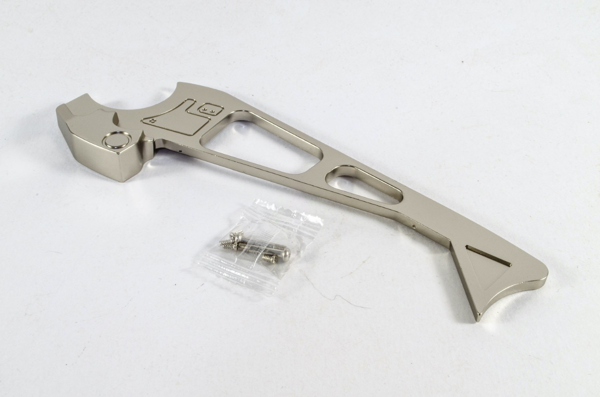
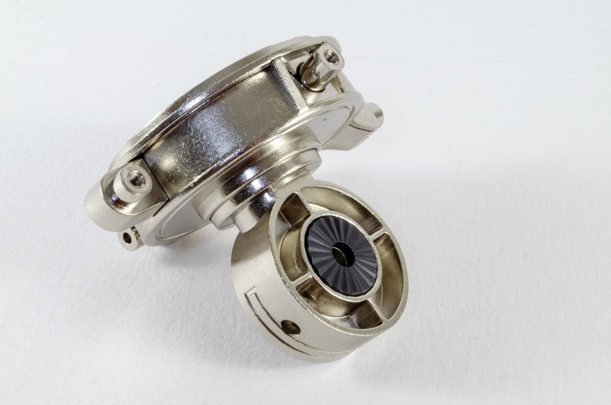
STAGE 55: FITTING A JOINT MECHANISM TO THE RIGHT THIGH
Unlike the other stages with their plastic moulded boxes, this part is packed into a sleeve and then popped into a large card box. All that is contains is this part and a pack of 2mm nuts.

The hip part of the upper right thigh is now assembled by a simple push fit.

The instructions call for these 2mm nuts to be made captive by using some CA first but I found the nuts generally too tight to get into position properly. To fit this, I inserted a 2mm screw into each nut and then tapped the top of the screw to drive them down into the holes. You definitely won't need superglue here! 🤣

The hip is then pushed into position on the leg.

STAGE 56: ASSEMBLING THE RIGHT HIP JOINT

In a random act of electronic haze, my 3 assembly photos have disappeared from both my card and Mac. Anyway, this is a no-brainer. This pack allows us to fit the right thigh to the Terminator. The open plastic cap bitts within the top of the thing, followed by the ball socket which locks into the pelvis. The closed plastic cap then sits atop this and tiger this is followed by the metal dome cap and then the last cap (shown at top). The latter is secured with four 2mm screws and it needs to be tight. The leg is still sloppy at this stage, but that's ok....

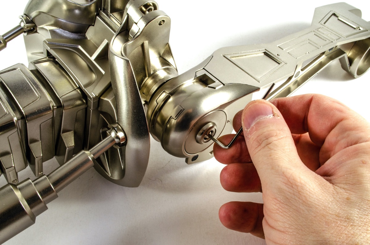
STAGE 57: FINISHING THE RIGHT HIP JOINT AND ASSEMBLING A LEG PART

In order to be able to adjust the position of those thunderous thighs, but so keep the model stable, another cap is now added to the hip area. This is then screwed into place with a hex screw. You will slacken this to position the leg before tightening to lock in place. For the moment, I've just left it in this position.

That leg needs more muscles, and here is the inner muscle being built.

STAGE 58: FITTING PARTS TO THE RIGHT THIGH

Not too much in this pack but it's got what it takes. This simply screws onto the right thigh and helps to fix the inner small muscle in position.


STAGE 59: A MUSCLE FOR THE RIGHT THIGH

The leg joint (presumably the knee?) is first assembled by gluing the ratchet in position. This is then set aside until a later date.

The leg muscle piston is now built, with a screw holding the rubber grommet in place.

The front leg muscle is now fitted...

STAGE 60: MORE MUSCLES FOR THE RIGHT LEG
Another joint piece. No idea what for yet (ankle?), but this is also glued together and set aside. Another muscle piston is now assembled and the main muscles connected to the right thigh. Sure looks powerful!


Here's the work so far. This is a BIG and HEAVY model!


-
I'm going to leave this image here as a placeholder. It shows the latest pack 5 completed, concentrating on lower spine and pelvis.
My camera memory card has gone AWOL for this build (Shelby not yet done, so not affected), but if it turns up, I'll add the images and text here.
I can tell you that this built up beautifully too and Terminator is getting very heavy at this point! 🤪
Can't wait to start building the legs.

- Egilman, Landlubber Mike, mtaylor and 4 others
-
7
-
Pack 4
Stage 31: Fit left shoulder accessories and add right shoulder joint

We have a little repetition here with the previous pack as we now add the left shoulder blade to the previous shoulder joint construction. Again, I took real care with this as the pin which pass though the parts and the neoprene sleeve, is plastic.


Stage 32: Complete a hinge joint on the right shoulder

The hinge joint is now built and added to the RIGHT shoulder joint.....not the one you just fitted the shoulder blade too. It's important you get that right. I didn't first time, but realised my mistake and corrected it. The arm can now be fitted to this joint. The Allen/hex key is used to lock the position and can later be slackened off for final positioning.


Stage 33: Left shoulder details

The thoracic vertebra is put to one side for a future stage, and the left shoulder hinge joint built up and fitted. A slot within the parts makes sure this will only secure in one position.


Stage 34: The first vertebrae

Now, the thoracic vertebrae from previous stage can be fitted to the vertebrae frame using the supplied nuts and bolts. The socket can also be fitted too, using more nuts and bolts.


Stage 35: Working on the thoracic vertebrae

This stage supplies the other socket for the previous frame we just worked on. After fitting this, the rubber caps are inserted within the sockets. These are identified as L and R for identification. These really do need to be properly placed. The caps will stop the later parts from scuffing inside the sockets.


Stage 36: Building the next thoracic vertebrae

I now built up pretty much the same as we've just seen, by fitting these parts to the next thoracic frame. The caps for these sockets aren't specific to which socket they fit into.

Stage 37: Components for the thoracic cage joint and vertebrae

Whoops, I lost my parts shot, but never mind! The thoracic cage joint is built by pushing two dome head parts into position and securing with a single screw. The finish is a little slack when fully tightened, but I'm pretty sure that's how it's meant to be. The remaining socket is added t the thoracic frame and the cap pushed into place.


Stage 38: Components for the thoracic cage joint and vertebrae

Ok, we know the drill with this assembly. Once this is built, the vertebrae shaft is screwed into place on the frame as shown.


Stage 39: Connecting the right and left shoulders

We really start to see some heavy metal coming together with this simple stage. Once the ratchets are glued into the cage shoulder connector, the right arm/shoulder combo can now be fitted to it, followed by the left shoulder.


Stage 40: Creating the thoracic cage

Another seemingly unassuming pack, but will really start to bring the T-800 together! The two shafts are screwed into the same frame as before, followed by the thoracic cage base.


The arm unit is then slotted into place over the central cage shaft, and the thoracic connectors just sat int place within the sockets.


The head is now installed into the assembly.

...and the front part of the thoracic cage is fitted. It's very important that this is screwed up real tight so that everything is help secure, including that ugly mush head!!


Sorry for the bench top images in some photos. My workshop is a mess at the moment with a 1:64 HMS Victory prototype, and having just got back from my holidays, I wanted to plough straight into this build.
More next month!
- Papa, Landlubber Mike, Egilman and 5 others
-
8
-
Stage 21: Assemble right shoulder and connect up skull

Nice and simple. The ratchet discs are glued into the shoulder joint. CA is used for quite a few bits in this latest pack.


Some little covers are now glued into place to hide the jaw screws. I used white glue for these in case I need to pop them off afterwards and adjust the tension of the screws.


These little pillars are superglued into the top of the head. I can only think they are to stick to magnets on the later panel. These fit perfectly. The top of the head is then screwed into place, being careful not to trap the wires.


Stage 22: Connect the jaw, assemble the head

These are a little fiddly to make as there are tiny pins that are needed for the pivot. Once made, they are glued into position on the jaw, but left unglued at the skull so they can move when the jaw opens/closes.


And now for the face! This just pushes into position.


Stage 23: Assemble the right shoulder joint

Simply put....the shoulder joint. The instructions warn about orientation of parts, but they can be turned afterwards anyway. This is most important when it comes to fitting the later sections.


Stage 24: Connect right hand to right arm

I've looked forward to this....fitting the arm together!The knuckle is built, then screwed to the hand this then plugs into the larger lower arm piston, and then the other pistons are plugged into the hand. The springs are threaded through the holes in the hand and then connected to the lower finger area with a cap/plug that's glued in place with CA.


Stage 25: Assemble right shoulder

The shoulder can now come together. The orientation of the various orbital components is vital. Just follow the instructions to get it right! The joint is then closed up with the large captive spring.


Some detail is then glued onto the joint. I removed the chrome plating from any plastic that needs to be glued to the metal.


Stage 26: Connect right arm to elbow joint

This part now needs to be unscrewed from the lower arm so that the upper arm can be fitted. Ratchet discs are then glued into position.


The upper arm is connected to the lower arm with the forward piston first. This has a washer fitted to either side and is held captive by refitting the plate we just removed.

Now the rear piston can be connected once the small metal sleeve is slotted into place. A screw holds it secure.

The elbow pin is then inserted and tightened from the other side with a he'd-heqd screw. This can be locked and unlocked to position the arm.


Stage 27: Assembling left and right shoulders


The right shoulder socket is assembled and glued onto the joint. More superglue at work here!


Stage 28: Continuing assembly of left and right shoulders

Now for something meaty. The joint now has a neoprene sleeve fitted, followed by the shoulder plate and pin/cap assembly. This needs to be done carefully as the pin is plastic and is fragile until inserted. No.....I didn't damage mine!


More of the same for this, as per the other shoulder. There is some repetition in these stages as we are working on areas on both arms simultaneously.


Stage 29: Left shoulder build continues


Stage 30: extend the left shoulder


I'm presuming we start the other arm and continue with the shoulder in the next pack. I can't wait to start bolting sections together!
- GrandpaPhil, mtaylor, JeffT and 2 others
-
5
-
Pack 2 hit the doorstep on Friday.....before the postman scurried off in case he caught the Black Death from me, so I thought I'd make an immediate start on and supplement the skeletal parts I'd built from the previous pack.
PACK 2
Another sizeable box too with plenty of parts to play with. Let's crack on!
Stage 11: Assembling neck and jaw joints
Well, we've started the head, so we may as well get some neck done. This pack contains half of the neck, the neck joint and some bushes/screws.

The first thing to do is to connect the two halves of the neck knuckle joint. Three screws does this job nicely. I used a thin screwdriver because of diameter of holes.

The black plastic head motor joint that was made in Stage 7 can now be fitted to the lower jaw. This is just squeezed in a little and aligned with the pin holes in the lower jaw. Once fitted, the jaw is then connected to the lower head section and the two bushes inserted into the connecting holes, followed by two fixing screws. The jaw will move and shouldn't be too tight.


Stage 12: Assembling the right forearm
This simple pack builds up into the lower arm...

First thing I needed to do was to use superglue to connect the muscle springs to one of the main forearm parts. I used CA gel for this as it gives a few seconds to get it exactly right.


The springs and the connector are then screwed to the main forearm 'bone', and the cap attached.


Stage 13: Assembling the neck and right finger component

Pretty obvious that this pack's main focus is the neck, and now we can complete it. The knuckle I previously made is screwed to the neck half that was supplied with that pack, and the lower head/jaw assembly sat into position. The opposite neck half is now laid over this and the final screws attached for the knuckle and head. To hide those screws, small plates are pushed into position over them, making the joint invisible.


I also assembled the half a finger supplies, exactly as I did in Pack 1. This will be shown next.
Stage 14: Adding to the right lower arm, and assembling fourth right finger

Three piston tubes are supplied here. these are slowed into the end of the cap and the piston tubes attached (shorter one in middle). A screw then holds everything together, whilst allowing the piston tubes to move freely.

The previous finger is now completed and fitted to the hand, as shown. In my case, all finger joints seem to be nice and tight, and again, I fit the plastic sleeve BEFORE adding the pin, as it stops the sleeve bunching up and not inserting fully.

Stage 15: Assembling part of the left head and the fifth finger of right hand

A whole new finger is supplied here and this is first built and fitted to the hand. All fingers are now present and correct! I resisted the temptation to form it into a well-known gesture! 🤣

The head side panel is also built as per the previous one.

Stage 16: Begin the assembly of the first lower arm

The lower arm now really starts to take form. The black plastic rotator ring that controls articulation, is push fitted to the arm joint built in Stage 7. This is then aligned with the large cuff in this pack, and the lower arm unit with piston tubs, slotted into position and screwed together.


The piston plungers now have their rubber sealing cups added, and these are inserted into the lower arm piston tubes.


Stage 17: Fitting sides of the head to the top of the head

Both completed head side panels are now screwed to the top skull piece from inside, and the unit put to one side until later.


The three ball joints are now screwed to the underside of the palm.

Stage 18: Assembling the eye motor support

Back to the head again now as the plastic bar from Stage 1 is now sat onto the pins on both eyes, locking them into position. To secure this bar in place, a plastic block is screwed into position above it. The eyes will now move freely, and together.

The eye motor is now secured in position. Everything was assembled as supplied as it all seemed to be aligned.

The upper face/eye unit is now screwed to the lower head. These screws are neatly hidden in the underside palette. Starting to look a little eery now. 😎

Stage 19: Assembling the head motor

Of course, the head needs another motor to operate the jaw, and first the two-part gearbox is assembled, and the motor secured to the motor housing.


The gearbox is now fitted to the motor housing.

Stage 20: Assembling and mounting the head motor support

After the motor support is securely fixed in place, the motor is fitted to it and the 'U'-shaped casing added. This holds the motor to the mounting. Make sure that you don't nip/damage any cables at this juncture, as there's a few wires waving about. (and no....I didn't damage any myself! 🤣)

The head is temporarily made to look a little angular as the two brackets are then screwed into position.

That's it until the next pack. What a great build!
- GrandpaPhil, Egilman, JeffT and 2 others
-
5
-
Hi all,
Whilst I've never really been a Sci-Fi fan, some stuff does grab me.....such as Blake's 7, Space 1999, Terminator, Star Wars etc., so pretty much a lot of the classic Sci-Fi. Agora's new T-800 hits the sweet spot for me, and in a massive half-scale too! This has been previously released by Hachette in other sales territories, and this release incorporates the fix to the original floppy fingers problem that plagued the original release. The first pack is a sizeable box too, so time to dive in and start some building! This will be entirely out-of-box, with no mods etc, although there are some out there if you do a little searching.
PACK 1
Stage 1: Components for head and eyes
Just to tempt us straight away, it's common for these models to supply something very recognisable. In this case, it's the upper face in all it's metal, metallic glory.
The first step is to push the eye pupils/lenses into the chromed eye orbits. These are a nice, snug fit.

Next, taking extreme care with the wires, the LEDs are now pushed fully into the orbits.


These completed eyes can now be installed to the inner face plate. Orientation of these is very important as they will later be connected to a motor so the eyes will move from side to side. The outer pegs on these must go upwards when fitted. Once in position, the eyes are then held captive by a brace which is screwed into position.


Creepy!

Stage 2: Components for the head and right arm
Hot on the heels of the upper face, I now build the upper jaw.
The face panel I just built is secured to the upper jaw as shown here. The two parts only fit together in one way.


Injection moulded plastic parts are supplied for the upper teeth, and these are installed as 5 separate parts, secured in place by a spot of CA gel as this gives more time to work with the parts and get them in absolutely the right position.

Some heavy metal work now as the upper arm begins construction. These parts form the swivel attachment at the shoulder, and align when these indents are together. Two screws hold everything securely.


Stage 3: Components for the right arm and right arm
The arm components in here form a piston which operates as the tricep. This is the main body of the piston, but as yet without the plunger. A screw holds all three components securely.


You now need to fit 3x AAA batteries to the box. Once you've done that, plug it into the small LED testing board, and then plug each eye into that board, in turn. Each should light very brightly.

Spreading the workload around a little, the first finger is now built, using the updated parts which stop the fingers from being floppy. In a change to the instructions, I find it easier to insert the sleeve between the joints, and then the pin. This was, the sleeve doesn't bunch up underneath the joint, and good the full depth. The small cap is then plugged into the pin, to finish it off.


Stage 4: New components for the upper right arm
We get a good stab at the upper arm with this stage, and start to see some things come together.
First, the bicep piston is built, and the plunger, complete with rubber seal, is inserted.


The plunger is also built and inserted for the tricep piston we built earlier.

The articulated should joint is now built. First, the previous part is now fitted with plastic grips.

Both tricep and bicep pistons are now fitted to the main bone of the arm, and the shoulder socket pushed into place. When everything is in situ, the large metal arm part from Stage 2, is then used to lock everything together via the piston screws.


Stage 5: Components for the lower jaw and neck
Back to the head now, with this lower head plate and neck socket.
The neck socket is first screwed together and sat into the hole in the lower head, once the black plastic ring is first seated.


A small cap now protects the top of the socket and a bracket screws into position to lock everything.


Stage 6: Teeth of lower jaw, and the bridge of nose
As with the upper jaw, the lower jaw now receives some detail treatment. All parts plug snugly into the jaw and are fixes with a spot of CA gel.

The nose bridge is also fitted after a little CA gel is put into the two locating holes in the face.


Stage 7: Components for upper arm and head motor

A little more attention is now paid to the should area of the T-800, with this ratchet joint. The ratchet place is first glued into the shoulder part, and the unit GLUED into the previous assembly, using more CA gel.


More upper arm parts screwed together . Once done, this is put to one side until we get another pack.


One last thing we need to do on this stage is to put the two plastic parts together that relate to the head motor.

Stage 8: Components for right thumb and right palm
Time to get handy again as we look at the right palm and some finger parts. The next finger fits together exactly as the previous, plus both are now finally fitted to the palm.

Stage 9: Components for right-hand side of head
This pack contains just two parts and a pack os screws. The right hand side of the head has its mechanical plate fitted and secured with two screws. That's it for this!


Stage 10: Inner eye sockets and right middle finger
Back to the head again. The eye sockets are now fitted within the upper metal face panel. I didn't find these needed any glue, and the instructions only say use it if needed anyway.


Oh, and another finger is built and fitted!

That's it until I receive Pack 2 🤪
-
15 minutes ago, gjdale said:
Wow! That’s a really nice build James. Looks like the modern equivalent of a Pocher model, only the parts actually fit properly! Now where’s the challenge in that?😉🤣
It also looks like there’s no painting required - is that correct?
All in all, a very, VERY nice model.......
No painting at all, if you don't want to.
I suppose you could always add more wiring under the hood etc. and small details like that, but it builds up completely out of box without 'needing' a lick of paint or anything else.


FINISHED - 1:8 GT500 Shelby Super Snake - Agora Models
in Non-ship/categorised builds
Posted
I'm not creating the manuals for these guys. I'm doing an abridged build for a magazine. I just thought I'd share the work here.
Remember, not all projects are 'modelling'") I certainly didn't describe it as such.
I certainly didn't describe it as such.