


James H
-
Posts
6,081 -
Joined
-
Last visited
Content Type
Profiles
Forums
Gallery
Events
Posts posted by James H
-
-
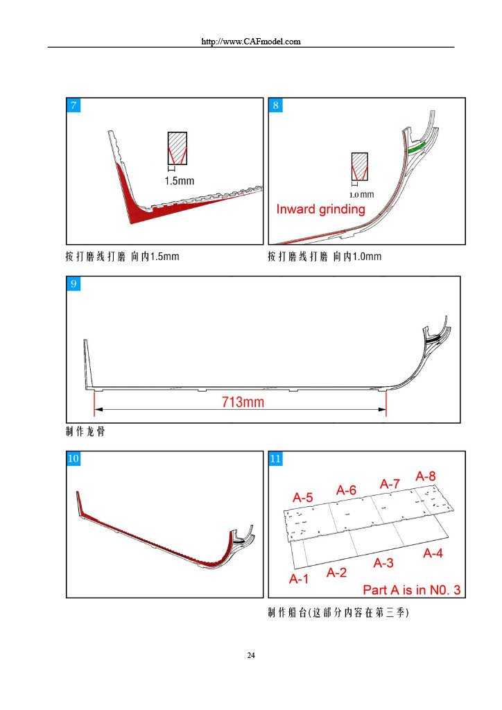
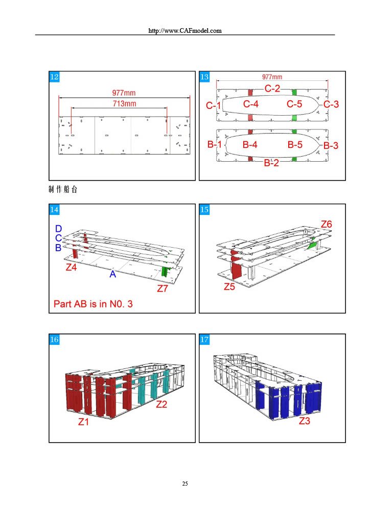
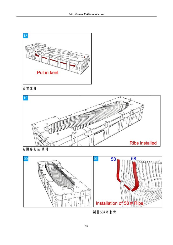
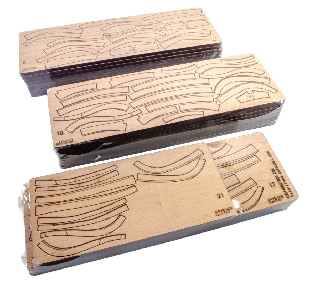
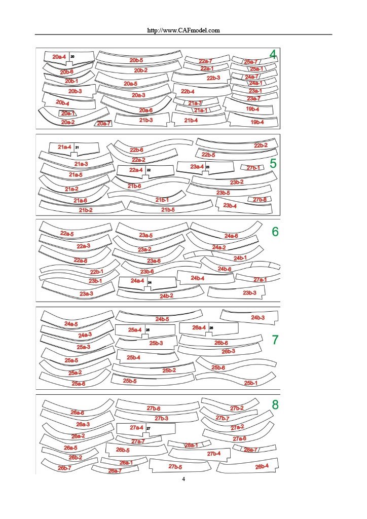
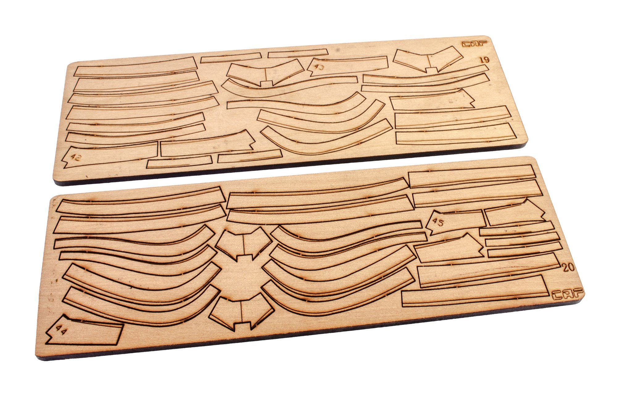
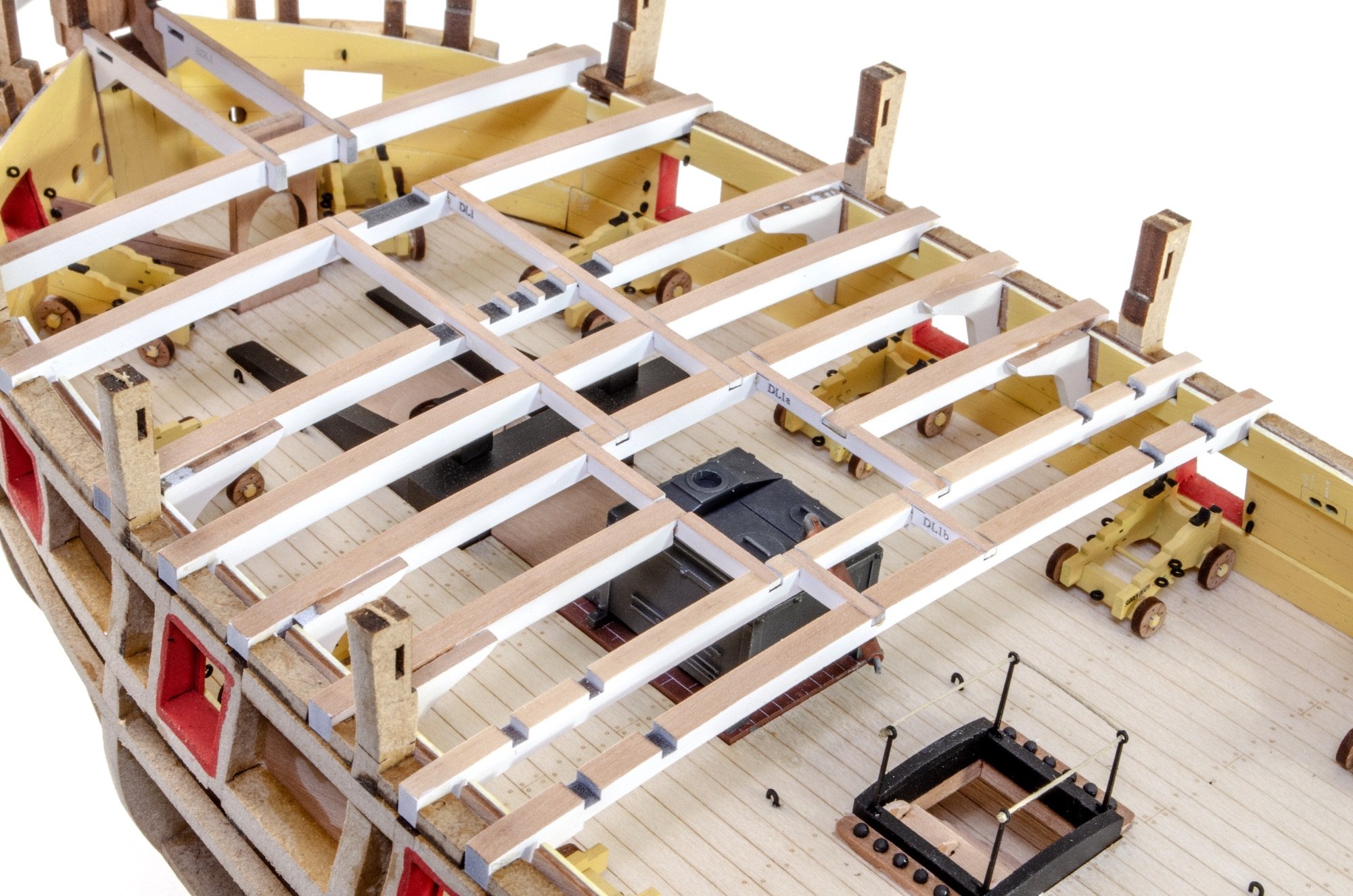
PART 4
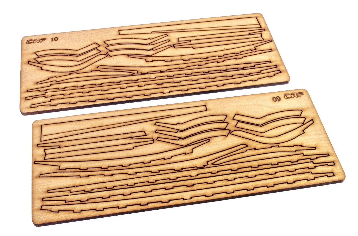
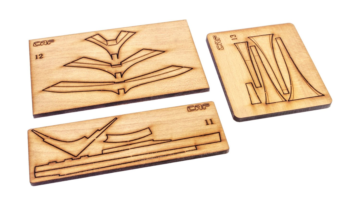
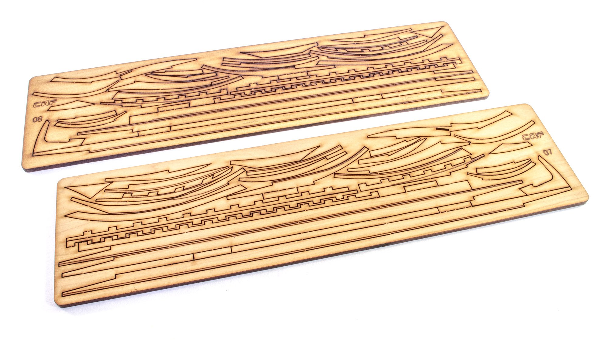
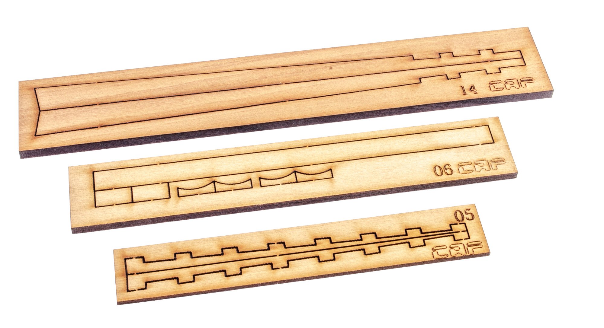
This pack is very similar to the previous in that it contains more framings, but also the keel, meaning that the hull really can now start to be assembled. Everything is packed into a single cellophane wrap as before. We've also been given more CNC-machined parts. It's quite unusual to split that large cradle into more than one pack, and not to have that as the initial box too.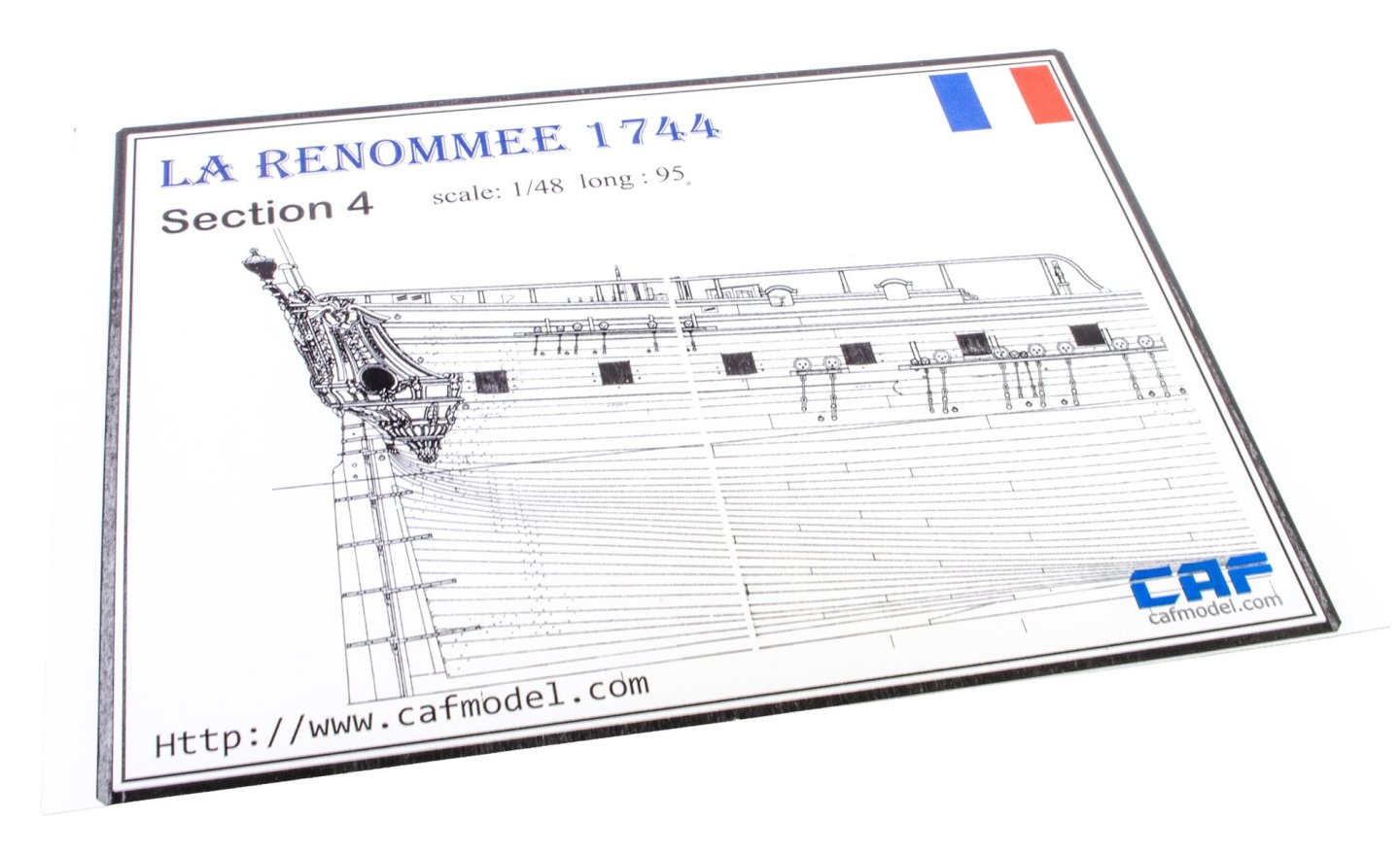


Instructions
If you'd like to see the whole instructions for this and how these first four parts come together, then they are available directly from the product page. Please check them out and if you're already tempted by this release, please tell Tom you've been following this topic.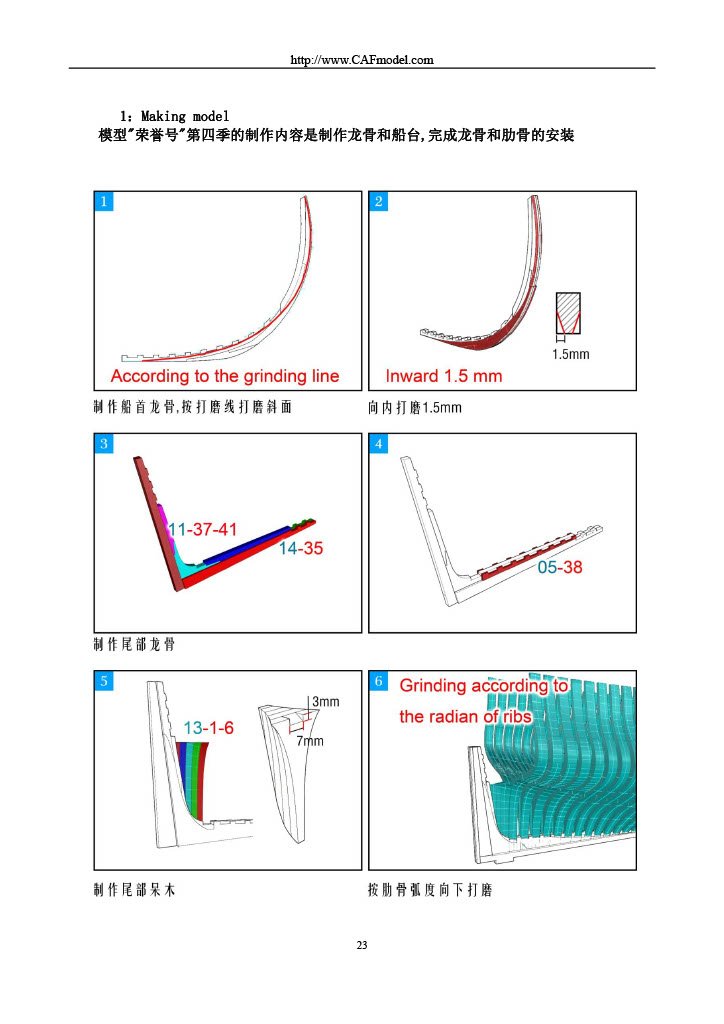
Part 4.5 will follow in a day or two.
- GrandpaPhil, Y.T., rcweir and 3 others
-
 6
6
-
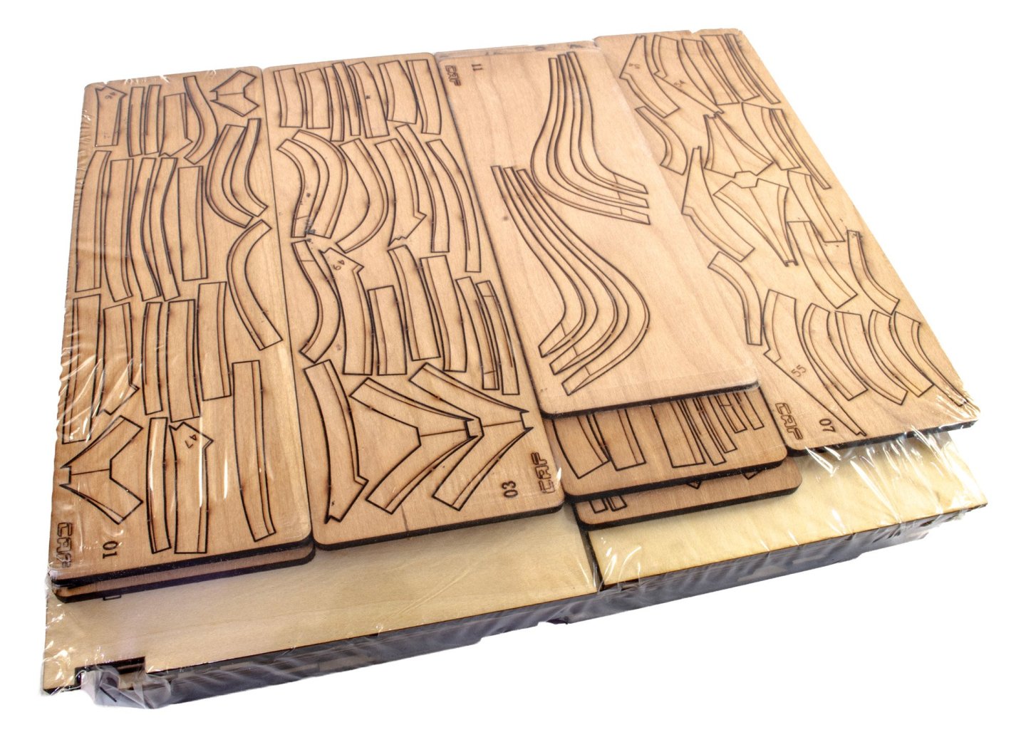
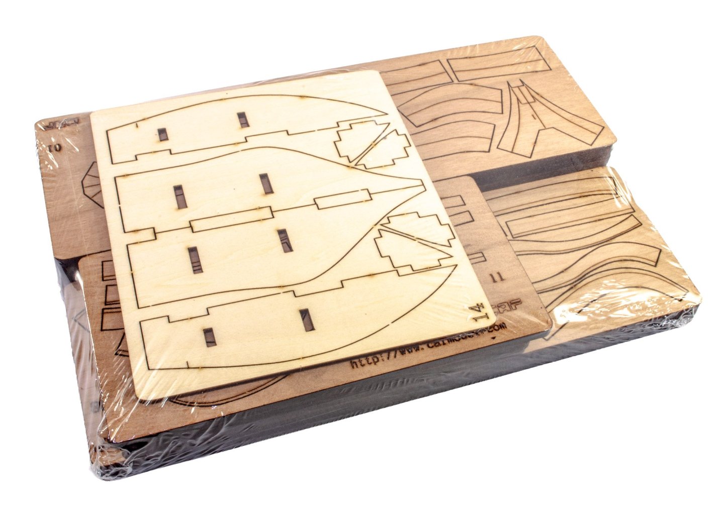
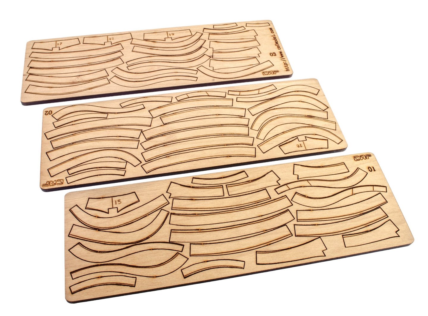
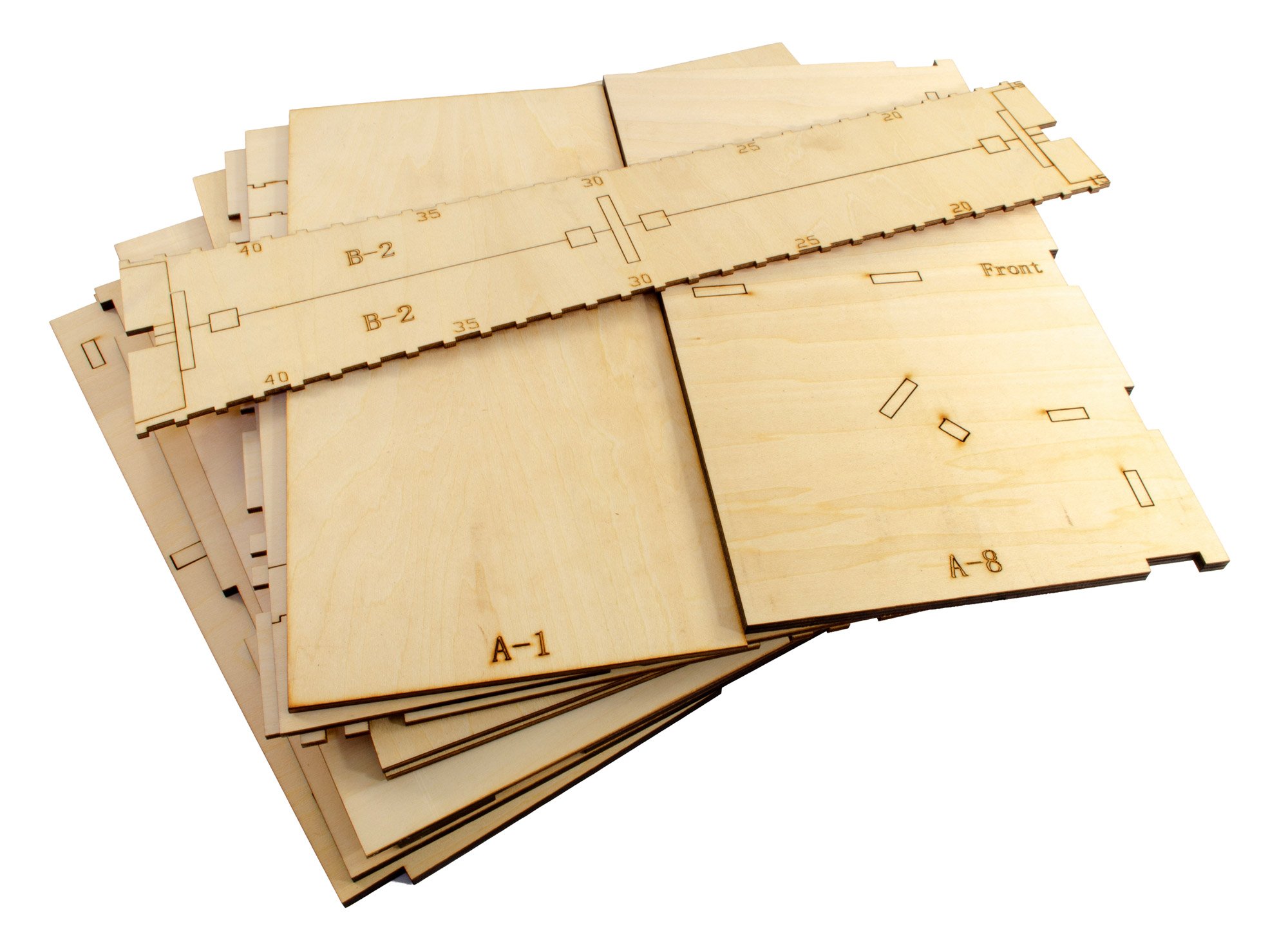
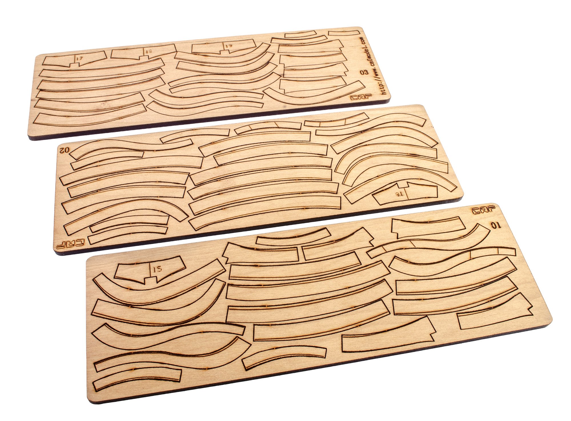
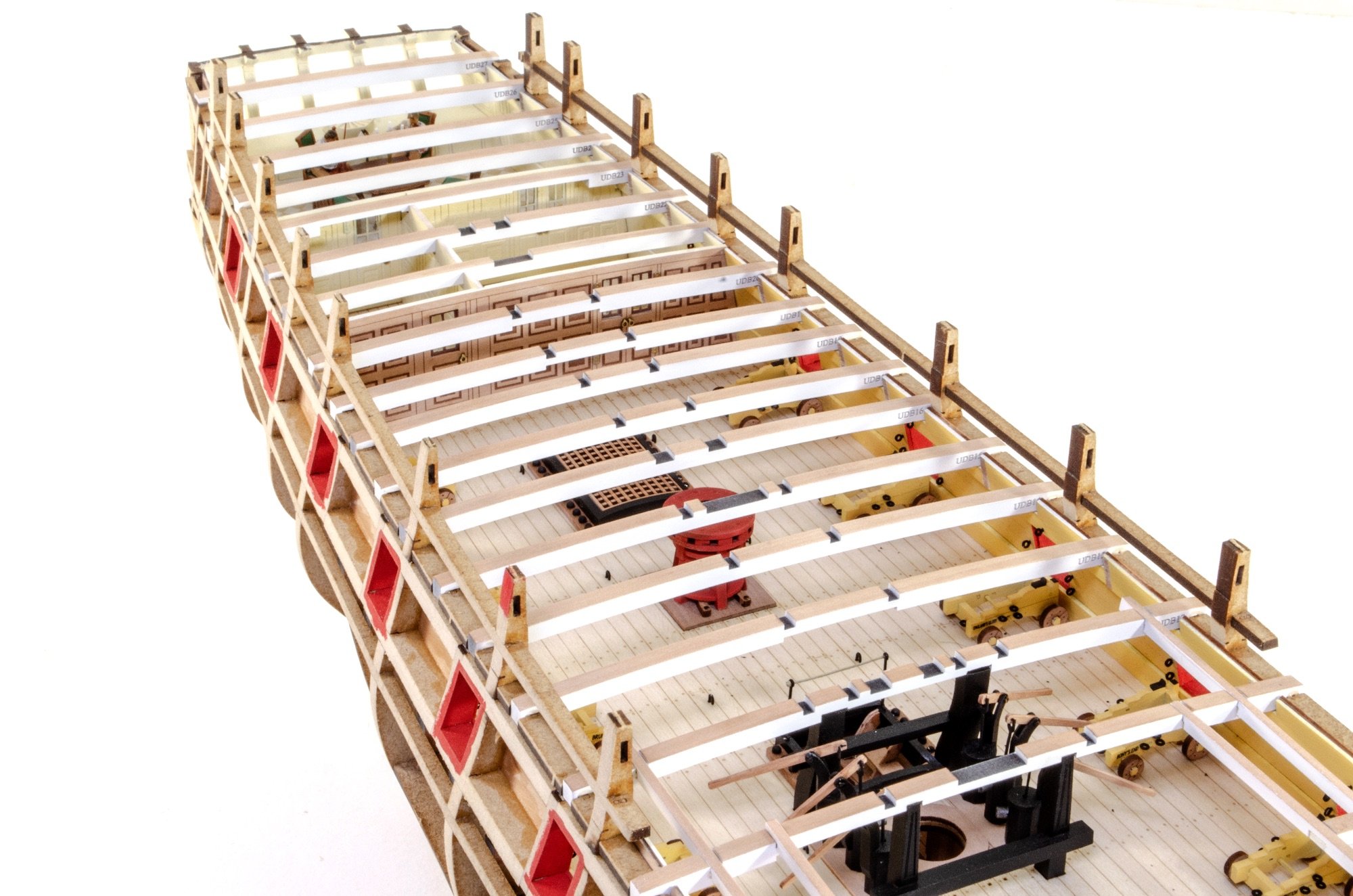
PART 3
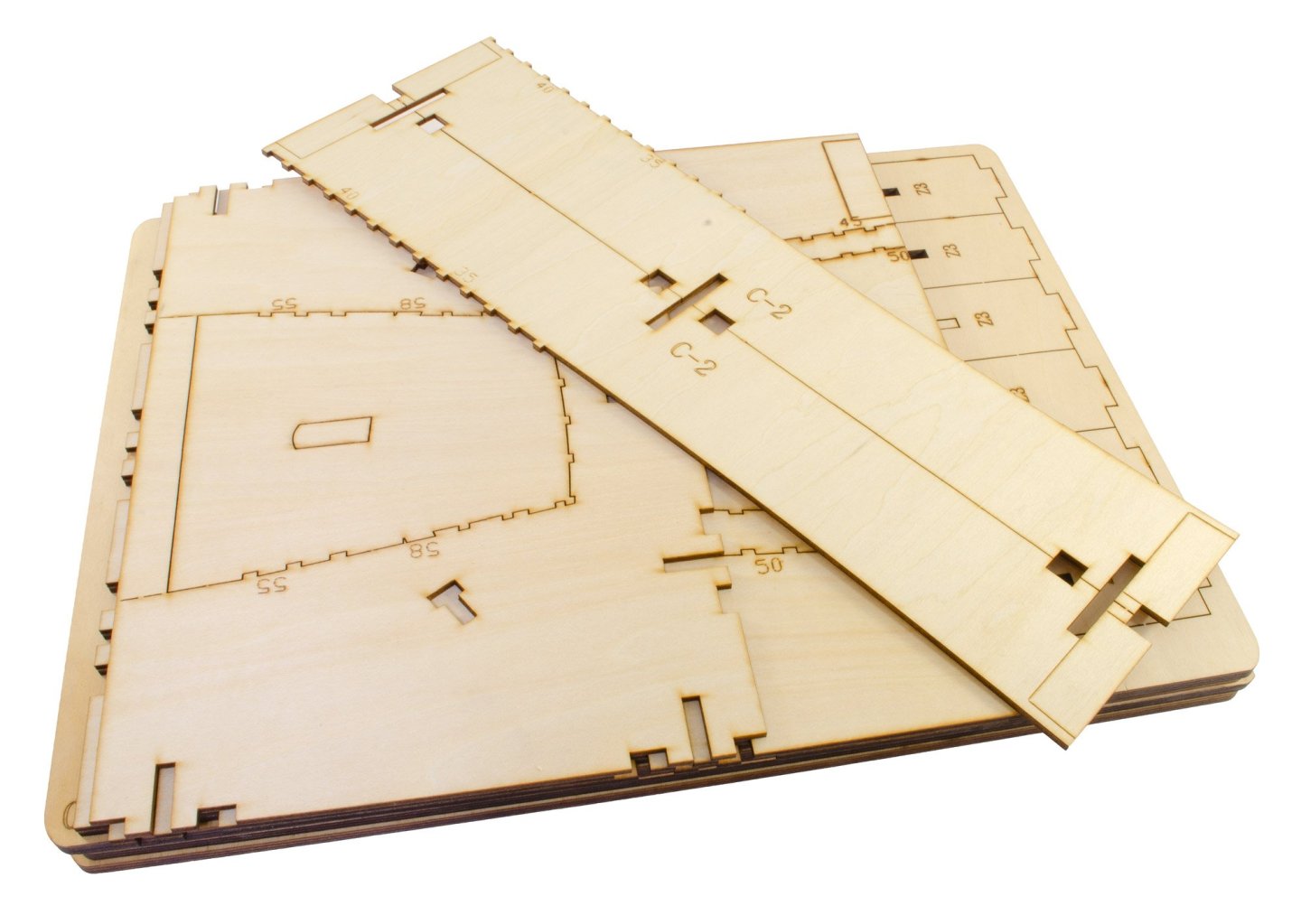
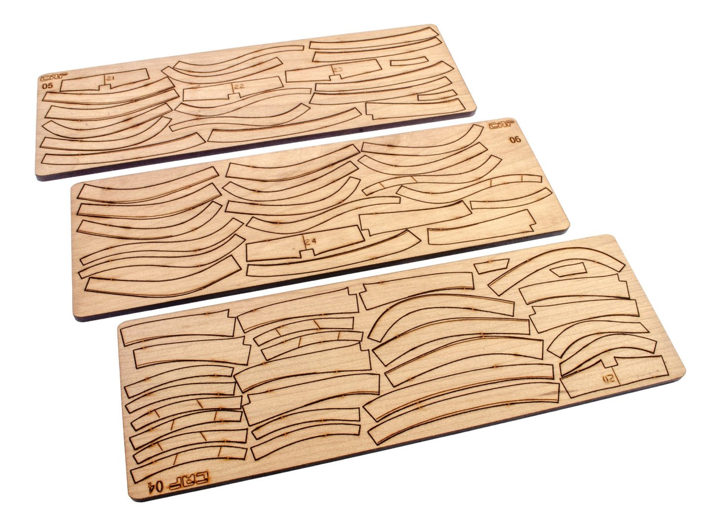
This is beginning to look all too familiar...but WAIT! We now also have parts for the hull jig! Not all though, as some are also supplied in the next pack, but at least you get a good start in getting that very large construction underway. As you'd expect, the cradle is constructed from laser-cut plywood.
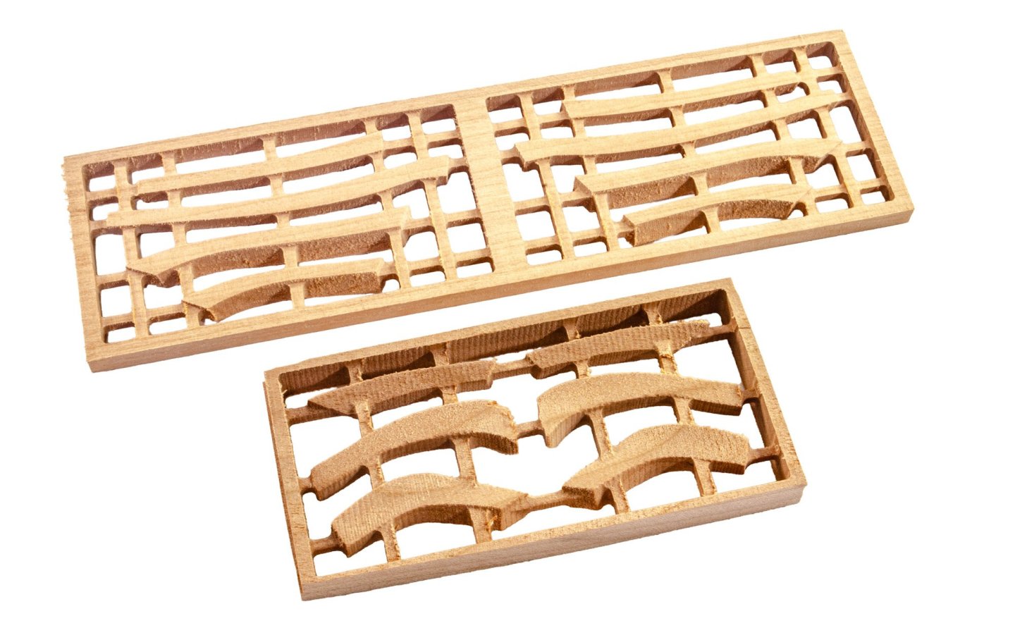
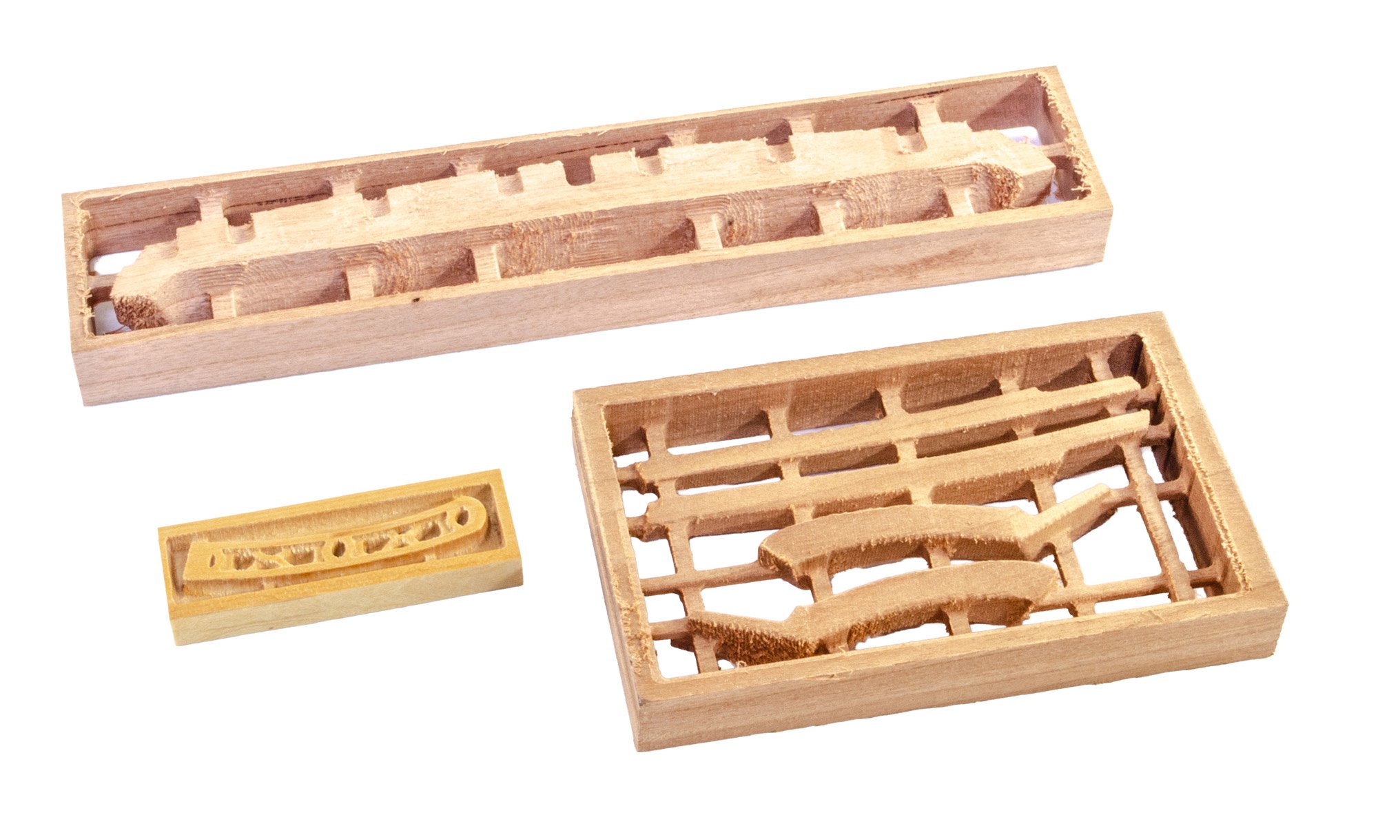
All parts in this pack are sealed in a single cellophane wrap. As well as more framing and that cradle, there are also two small frames containing CNC machined parts which relate to the stern of La Renommée. These just want freeing up and carefully sanding smooth.


Instructions
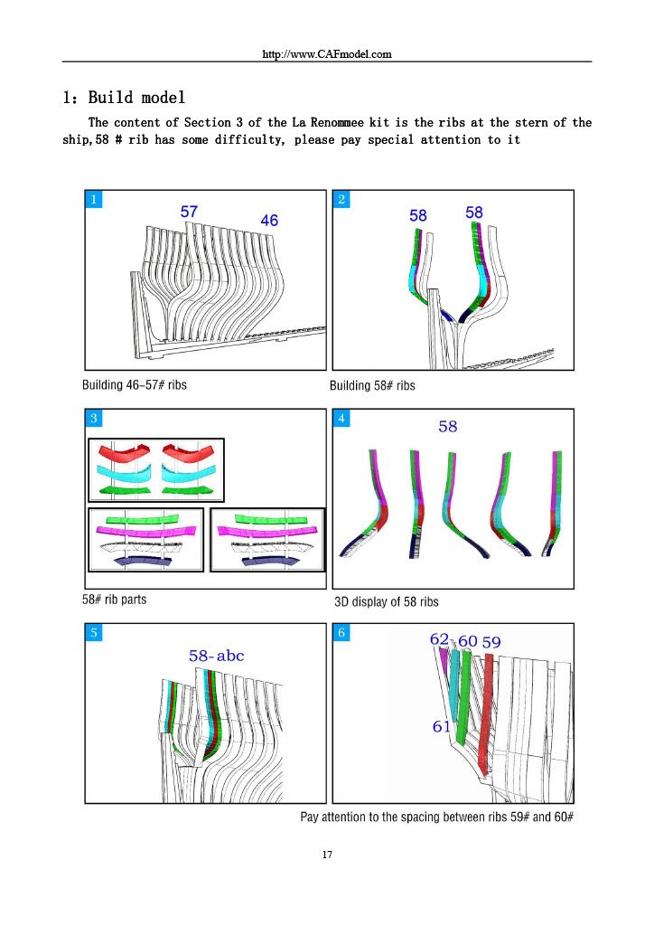
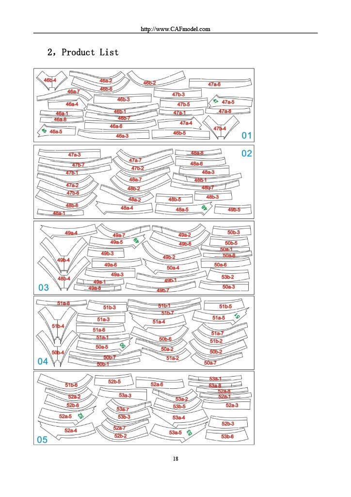
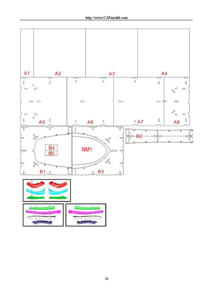
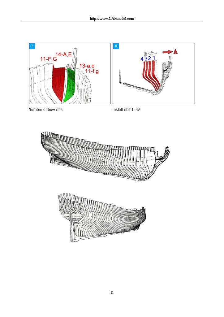
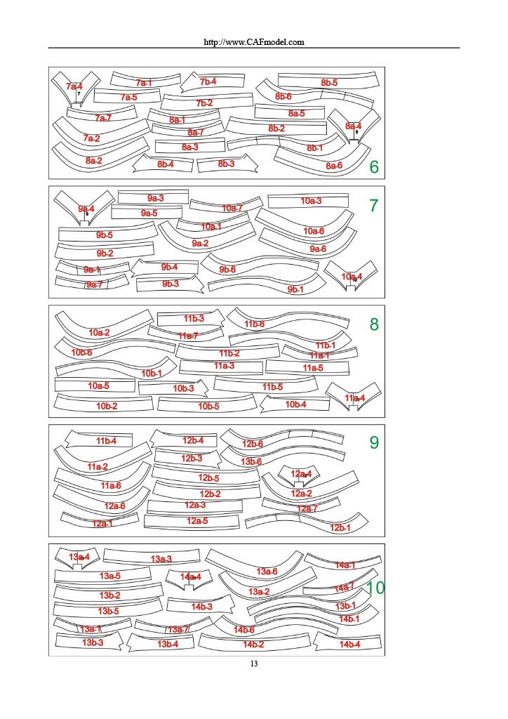
As well as another full size frame layout sheet, you can see the use of colour in the instructions, to denote key areas of construction, including the use of those CNC parts.
Part 4 will follow soon.
- GrandpaPhil, Ronald-V and chris watton
-
3
-
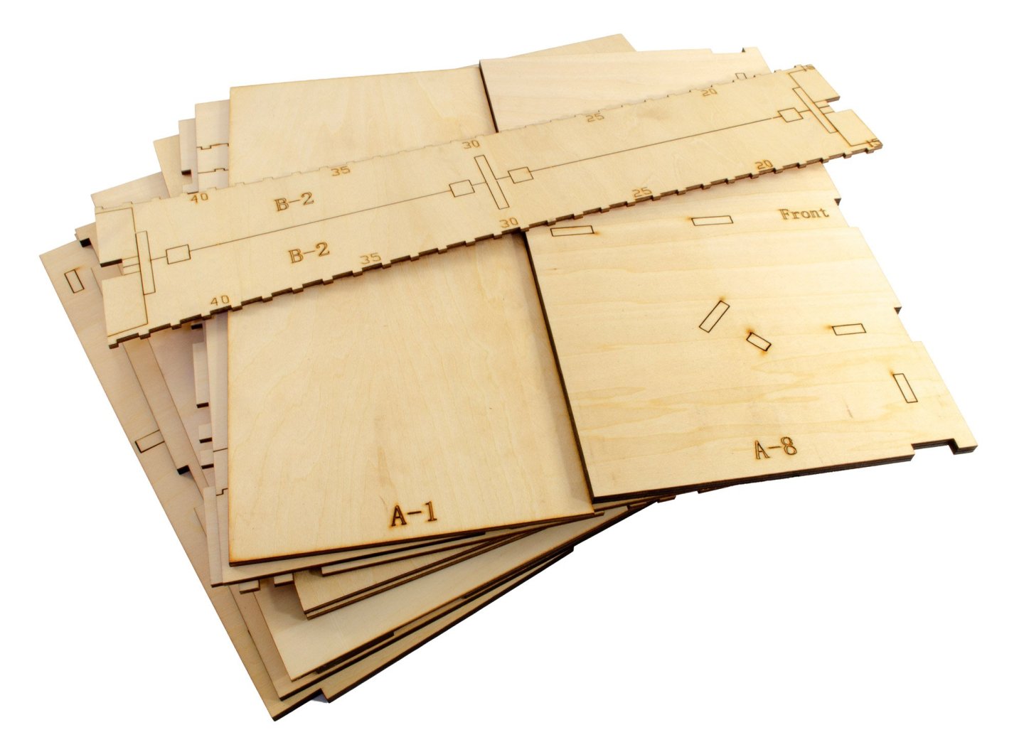
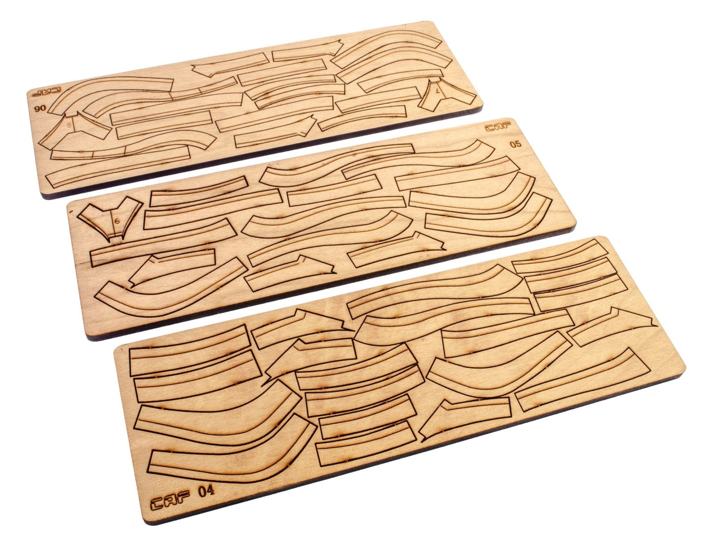
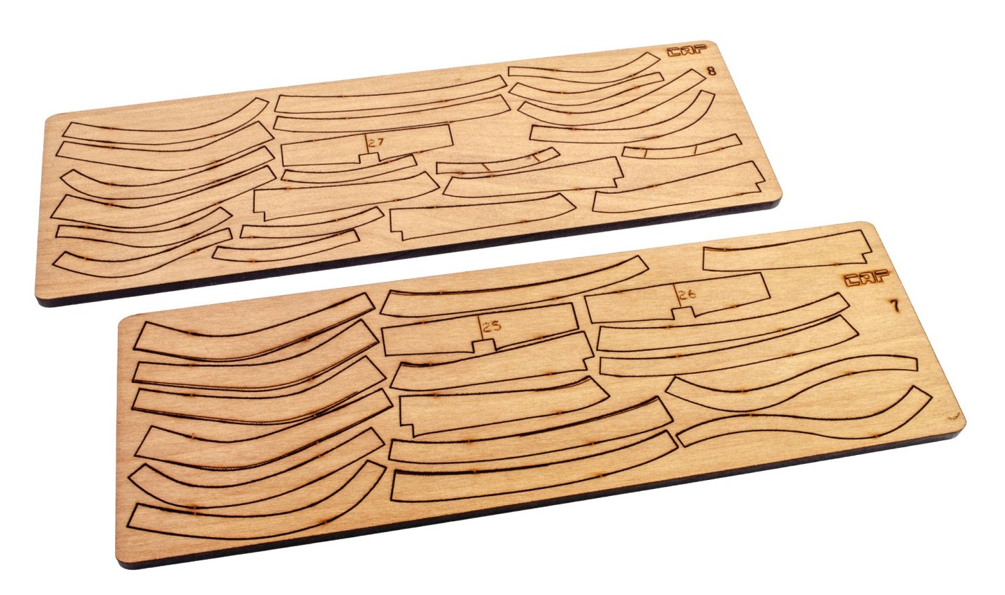
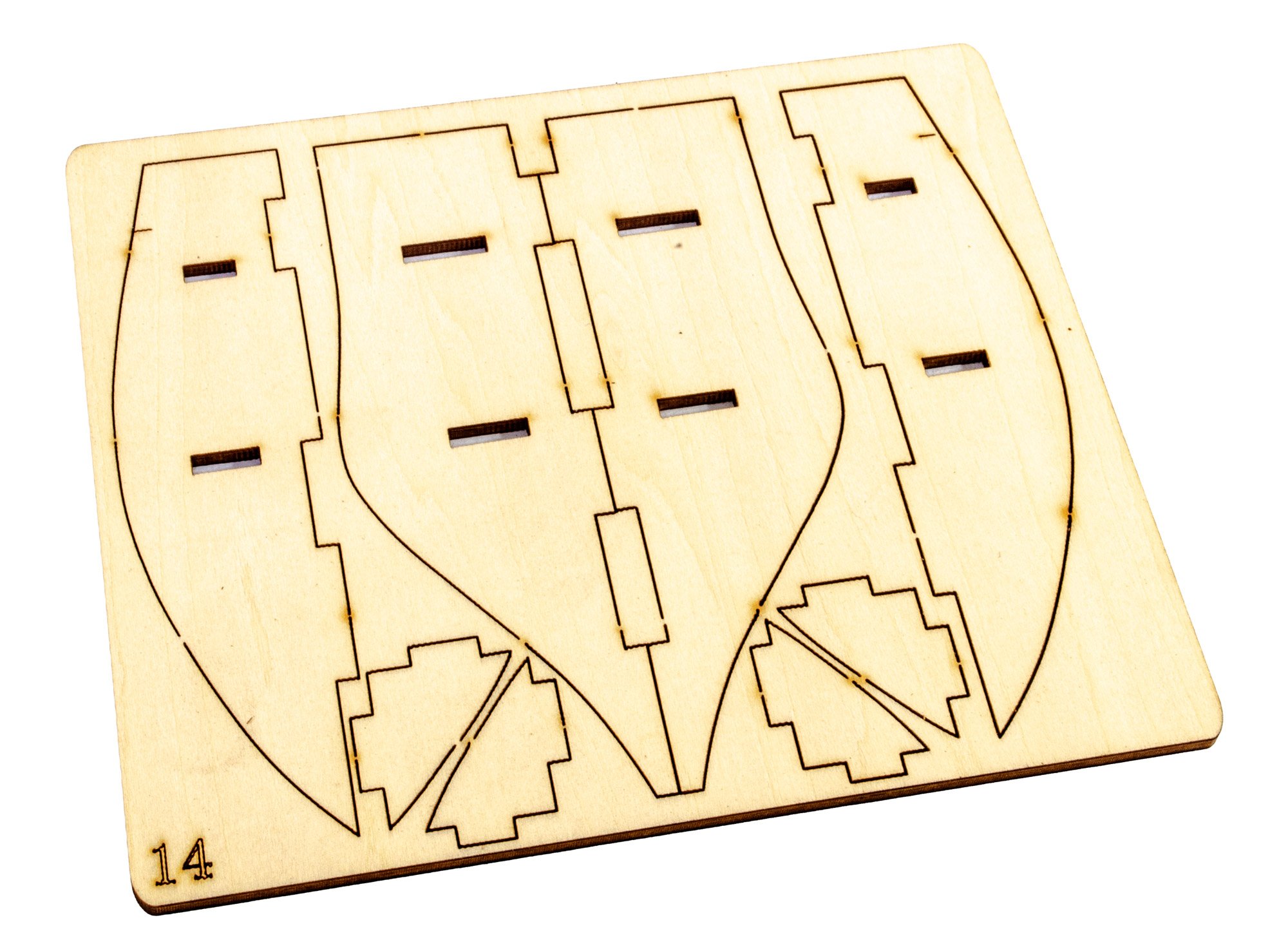
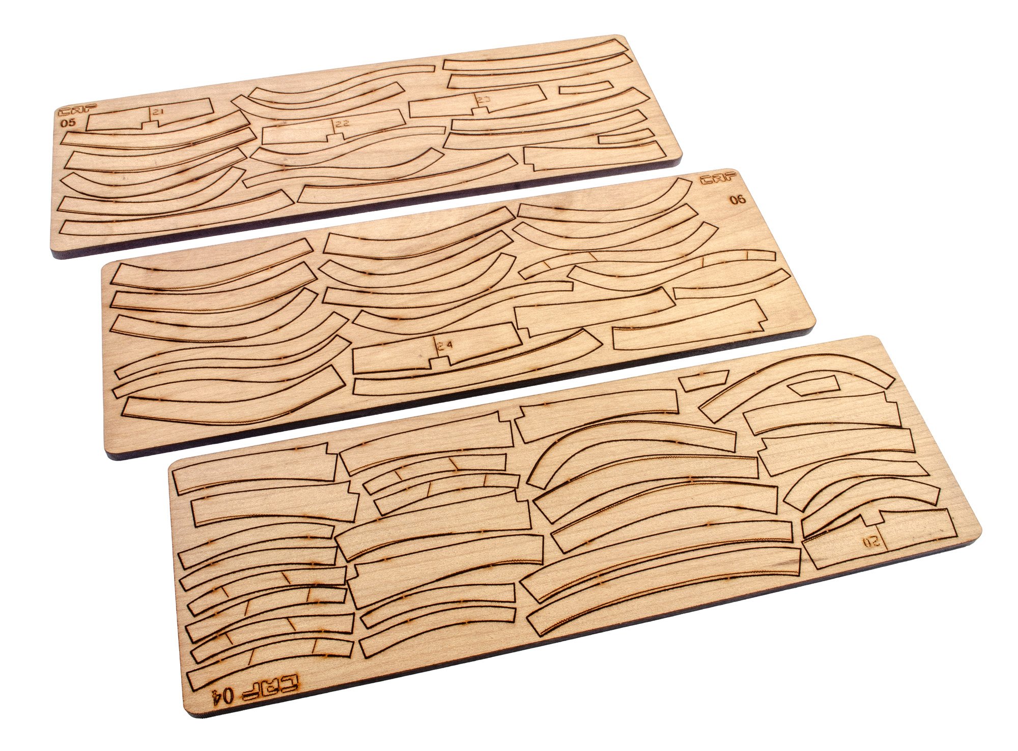
PART 2
This pack is largely similar to the previous, except a plywood jig is included for the modeller to build the bow frames around. At this stage, there's still no cradle as we are concerned with the building of those many frames. All parts are packed into a single cellophane wrap. After unpacking and photographing, tape was used to re-bind the parts to prevent any twist until I come to build the model.

Instructions
This is very similar to Pack 1, except the bow jig is illustrated. This looks very simple to build. Again, a full size sheet is included over which to build the numerous hull frames.
Next post will show Part 3.
- chris watton, GrandpaPhil and Ronald-V
-
3
-
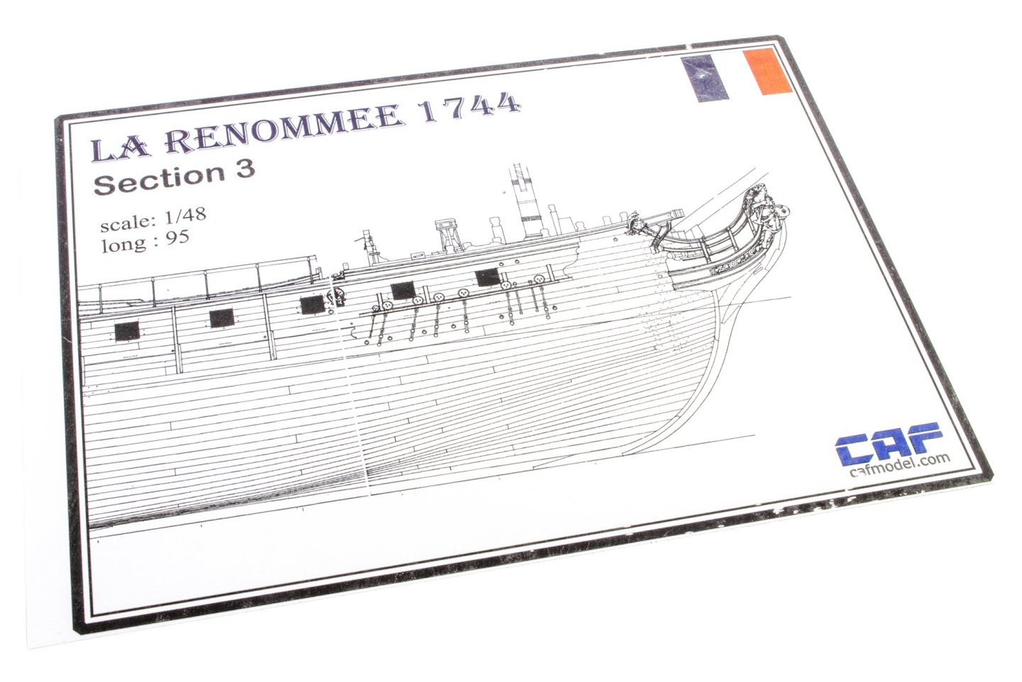
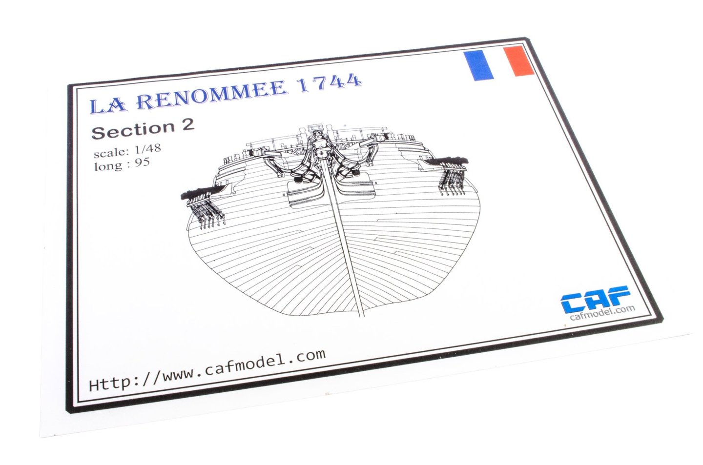
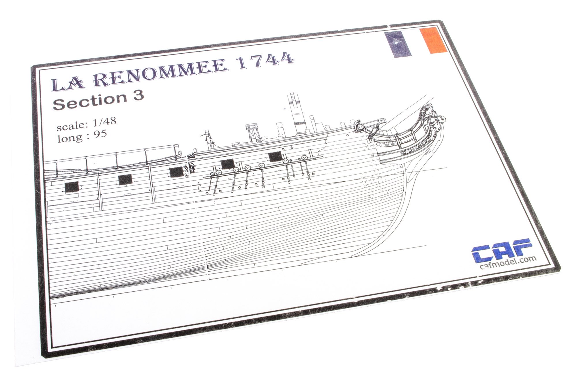
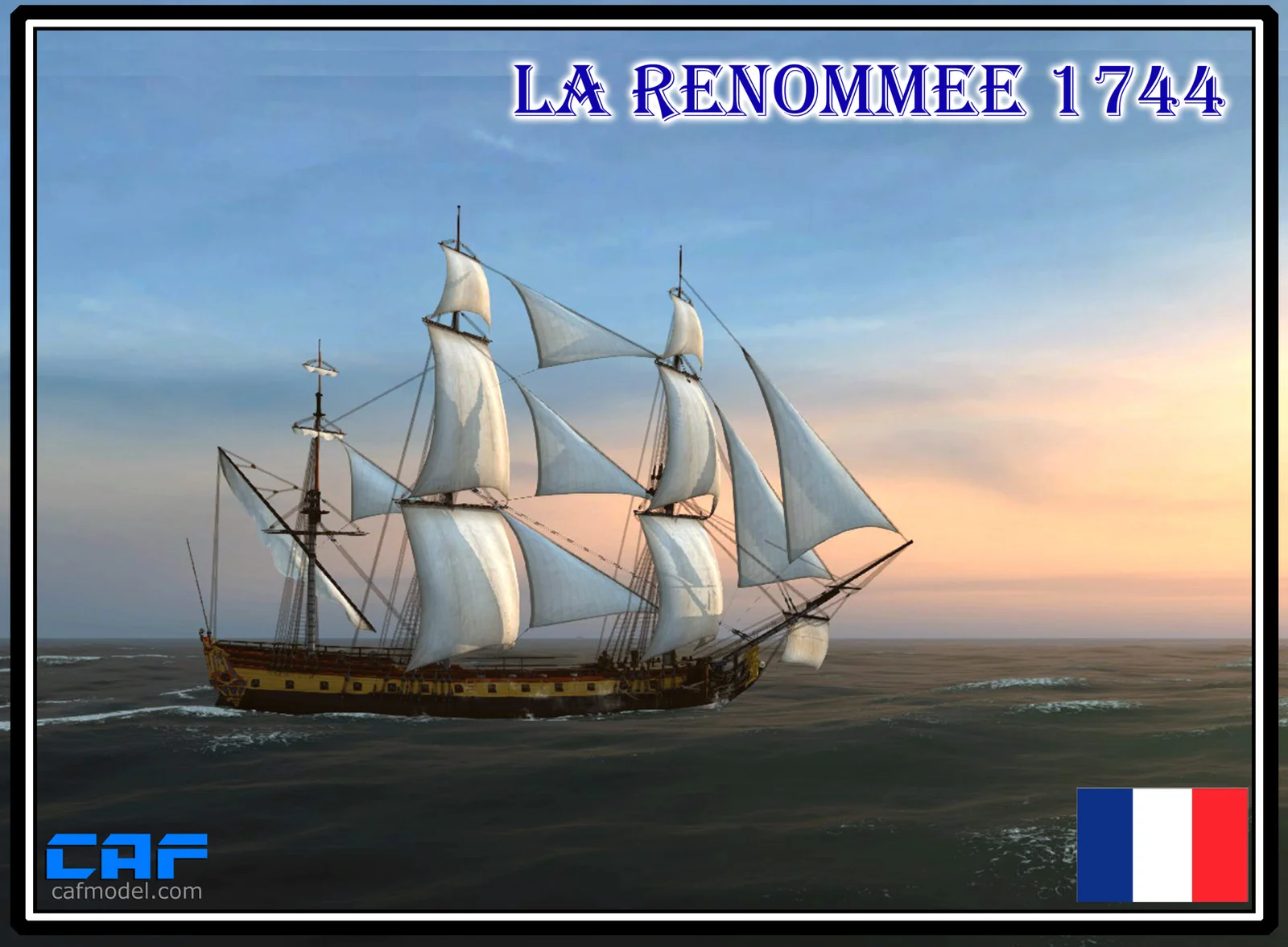
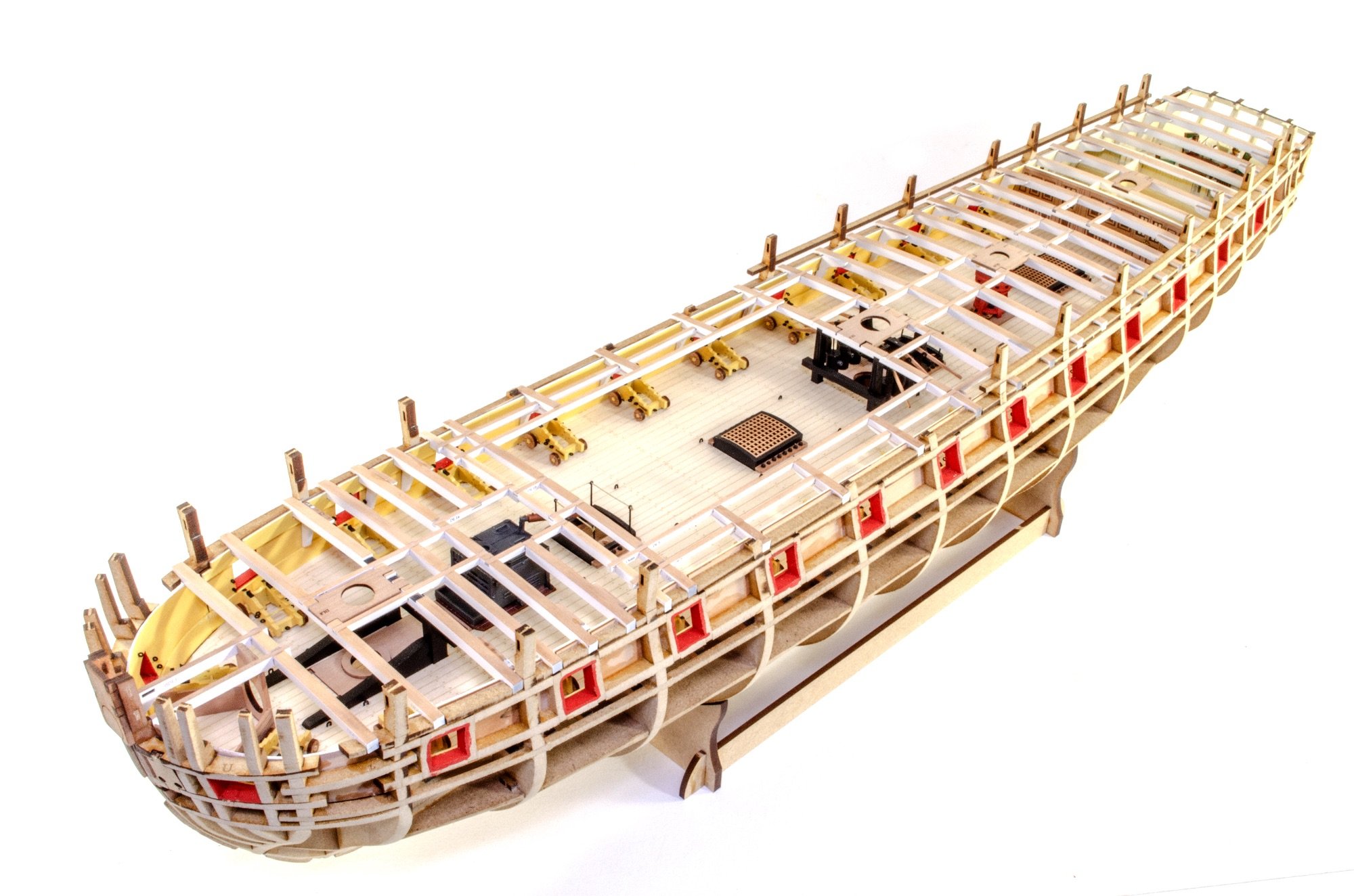
1:48 La Renommée 1744
CAF Model
Kit available in chapters - check site for prices (complete kit around $2500USD as time of writing)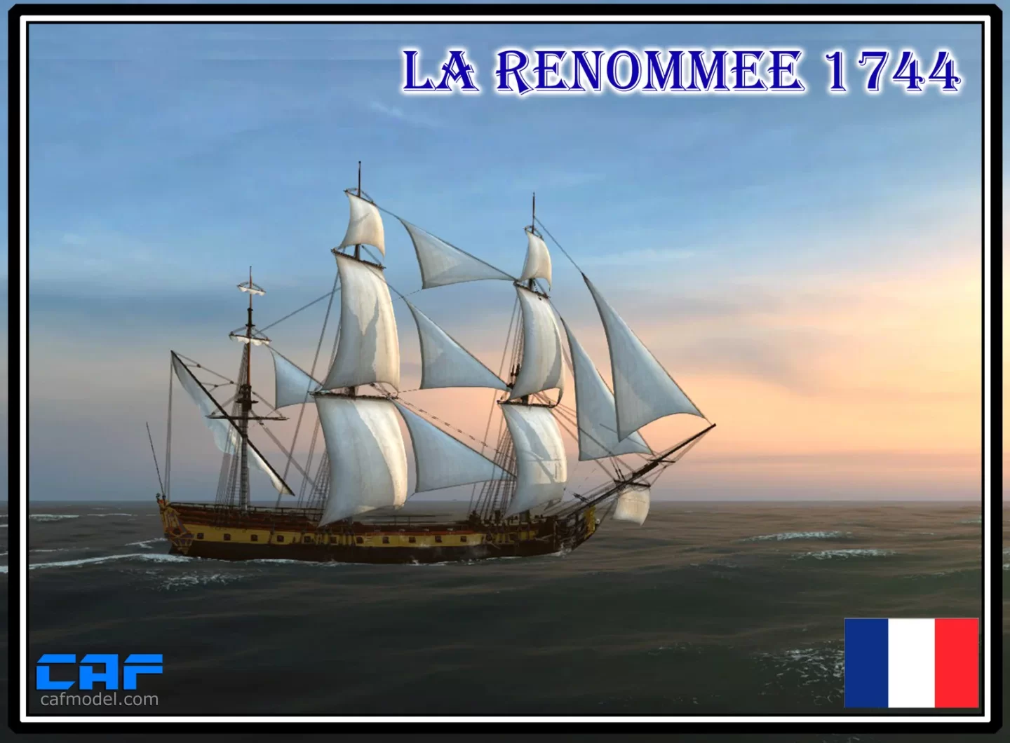
History
La Renommée was a French frigate launched in 1744 at Brest during the War of the Austrian Succession, at a time when France was refining the fast, lightly built frigate type that would soon dominate naval scouting and commerce warfare. Designed according to contemporary French principles emphasizing speed, maneuverability, and efficient firepower, she carried roughly 30–40 guns (depending on source and period) and was considered a capable and well-sailing ship. In 1747, while en route from France to the Caribbean, La Renommée was captured by the British after an engagement with HMS Dover in the Atlantic. Impressed by her design and sailing qualities, the Royal Navy took her into service as HMS Renown, reclassifying her as a fifth-rate frigate. Under the British flag she served for more than two decades in patrol, escort, and overseas duties, including service in the English Channel and the West Indies. After a long and relatively uneventful career, the ship was finally broken up in 1771, her longevity reflecting both the soundness of her original French construction and the Royal Navy’s appreciation of captured French frigate design.
The kit
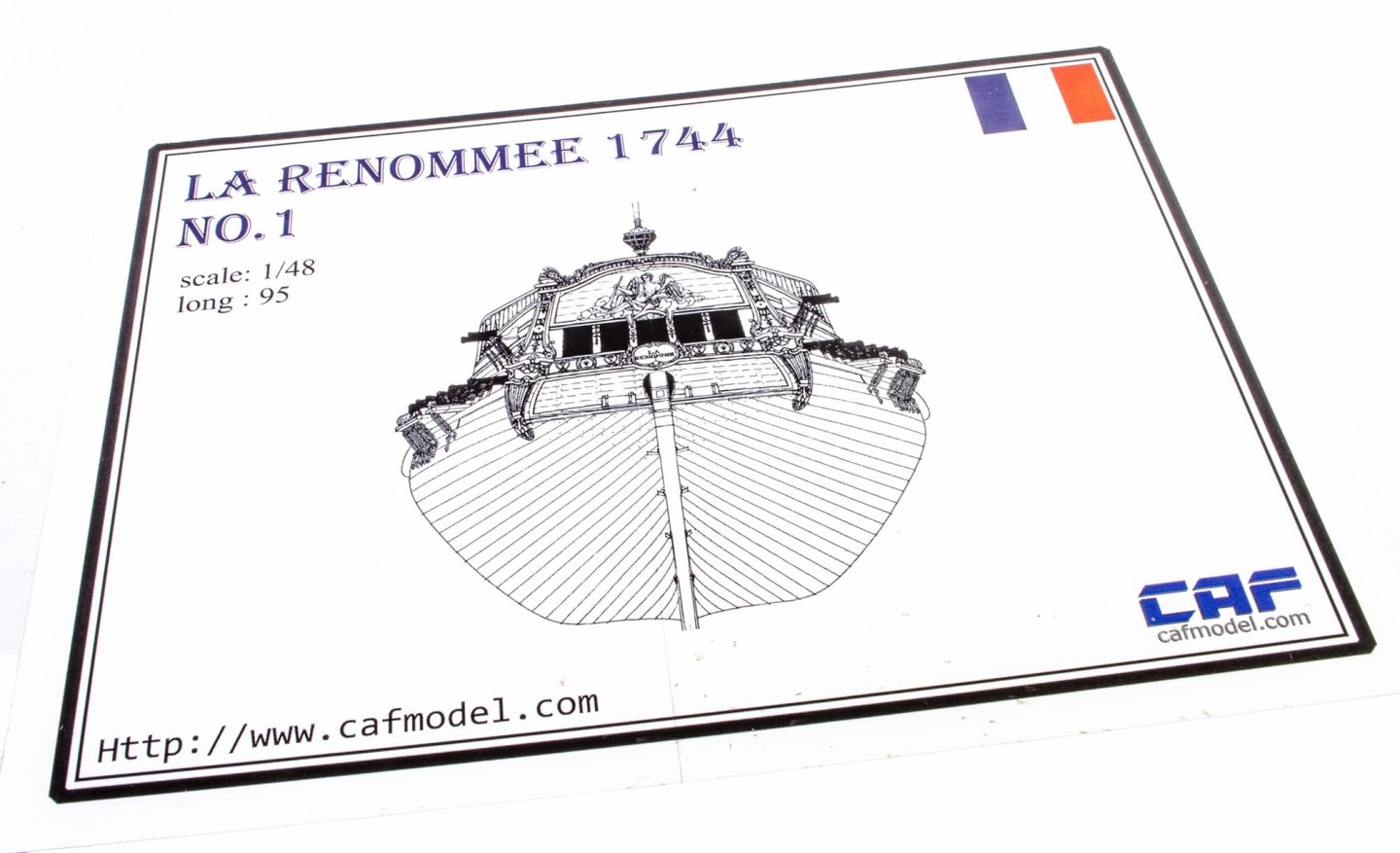
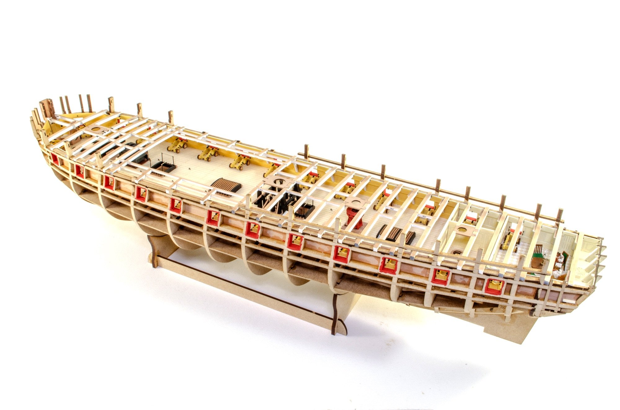
Here is the kit spec, as given on the CAF website. In 1:48, this is a very large model, especially if you complete with the masts and rig.
- Scale:1/48
- Length : 1230 mm
- Hull length: 927 mm
- Width: 550 mm
- Hull width: 250 mm
- Height: 950mm
- Hull height 250 mm
- Building jig included in kit
- Keel, rib, hull is in American cherry wood
- Hull and carvings are boxwood
- Boxwood figurehead with very high detail
- Deck uses white maple
- Guns, anchor, rudder hinge, brass casting, and many more metal fittings
- All laser-cut wooden sheets with quality wood ( minimal colour variation)
- POF kit, many high accurate ribs
- 8 pound class artillery * 26
- 4 pound class artillery * 4
- English instructions
- A0 drawing 1:1

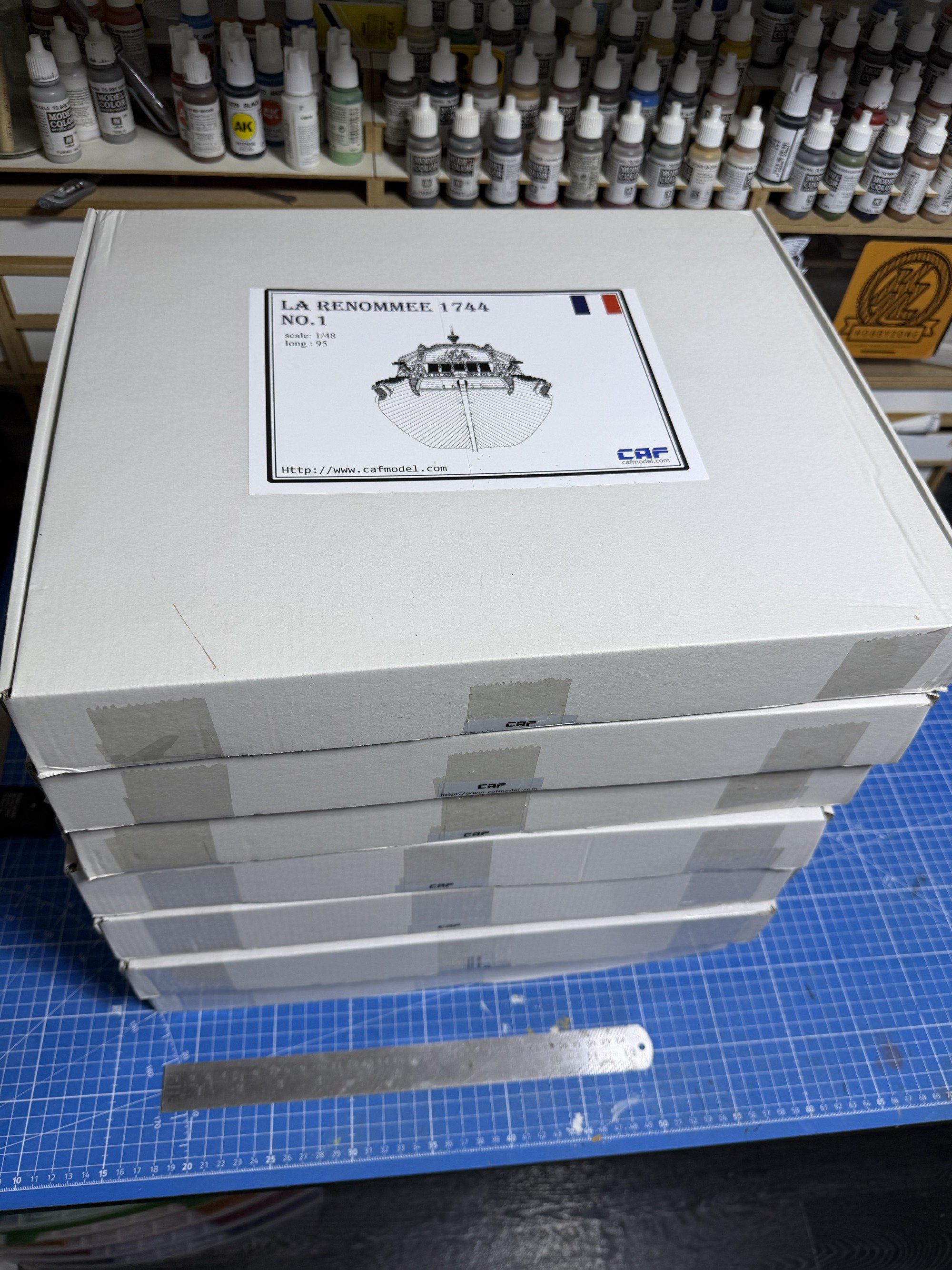
This is the latest kit, brought to chapter completion by CAF Model of China. The main release comprises SIX individual boxes, with an optional hefty Part 4.5 that contains all of the interior, should you with so fit it (and why wouldn't you!). So yes, I have SEVEN boxes here, and the weight is not insubstantial! I don't know if it's luck or design, but I've never had any import duty to pay on Chinese imports in the UK. All of these kits were sent in two shipments, with them being heavily protected and wrapped in heavy duty film. Everything arrived in A1 condition. All parts are individually sealed with a product label.
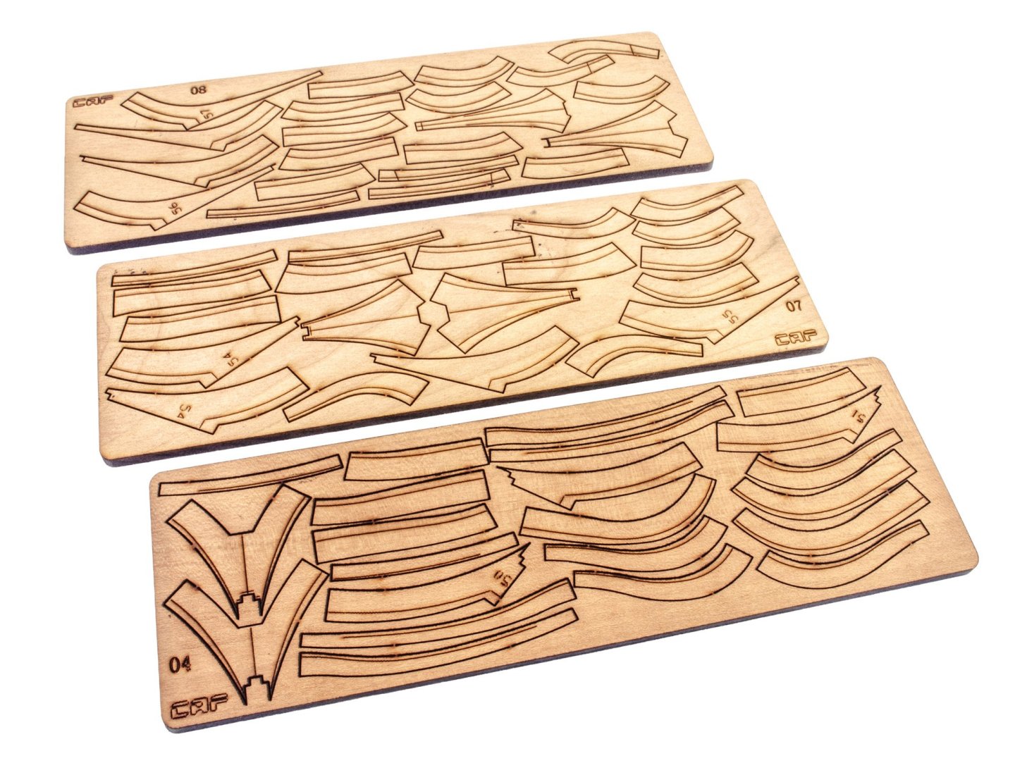
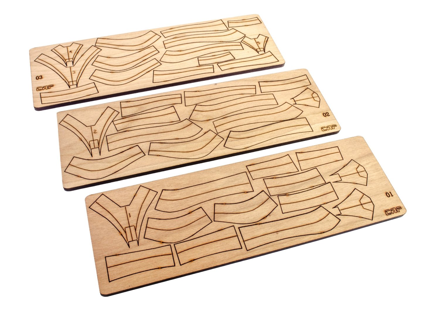
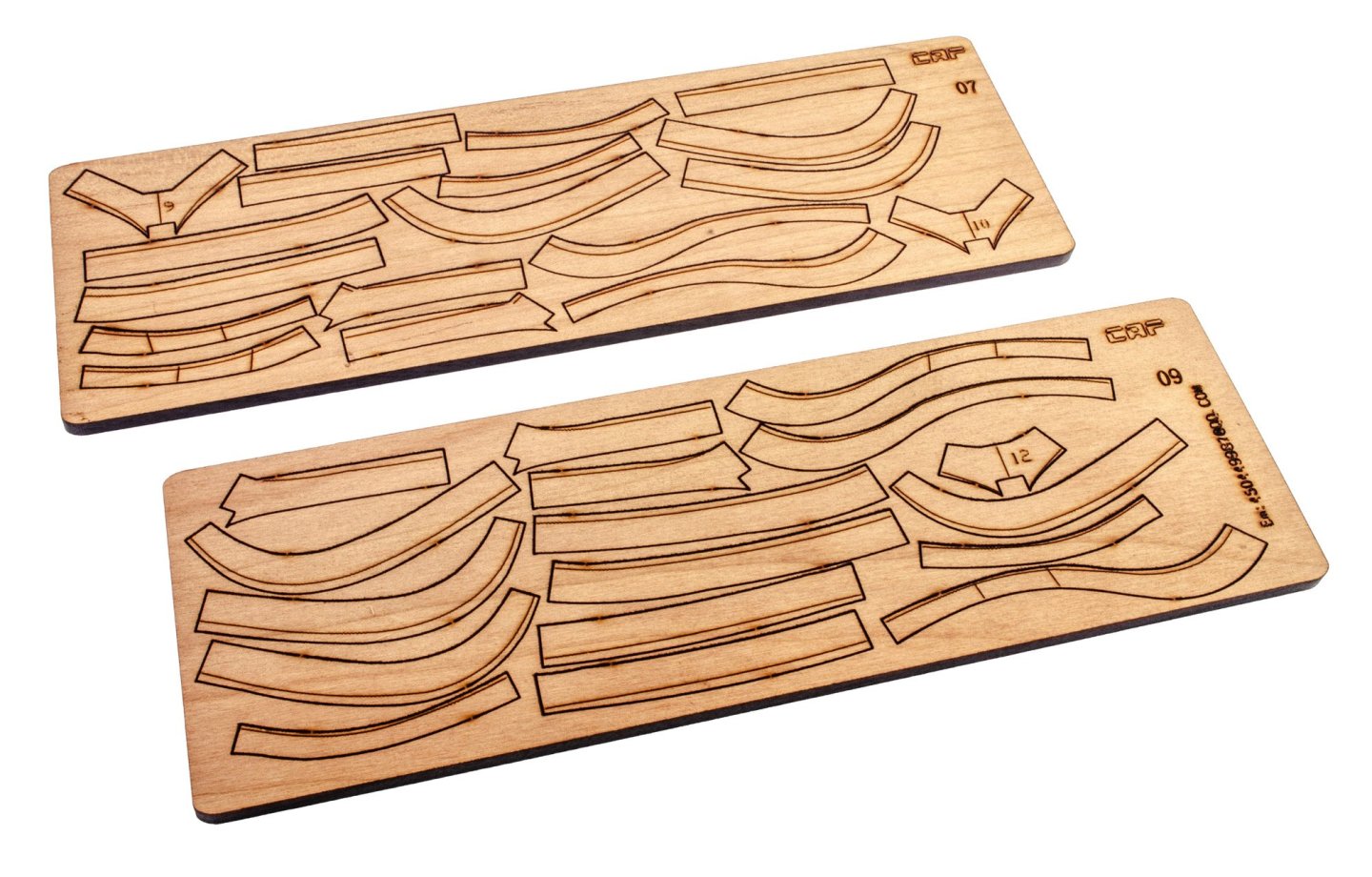
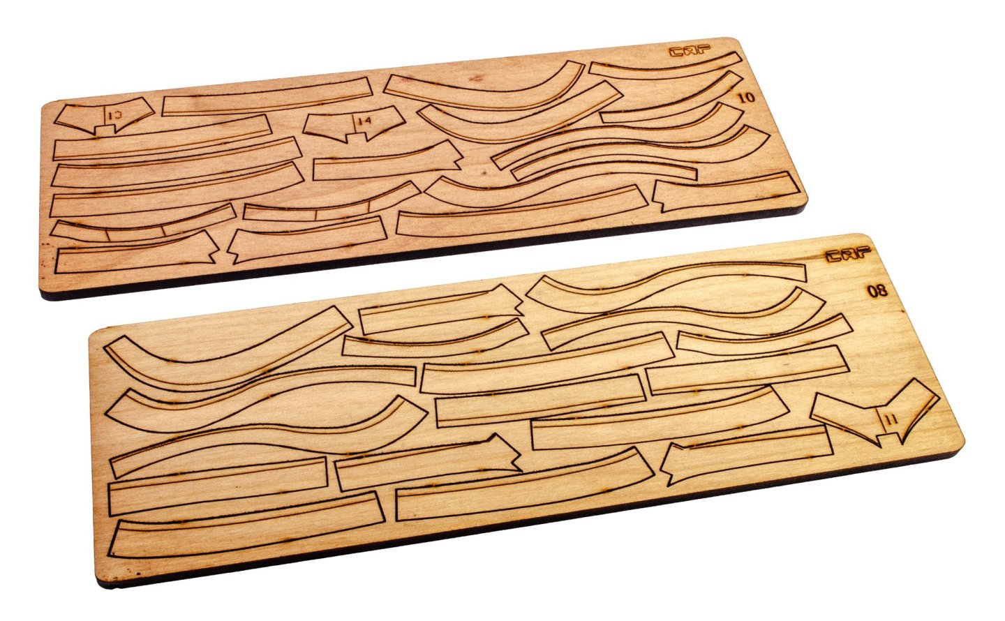
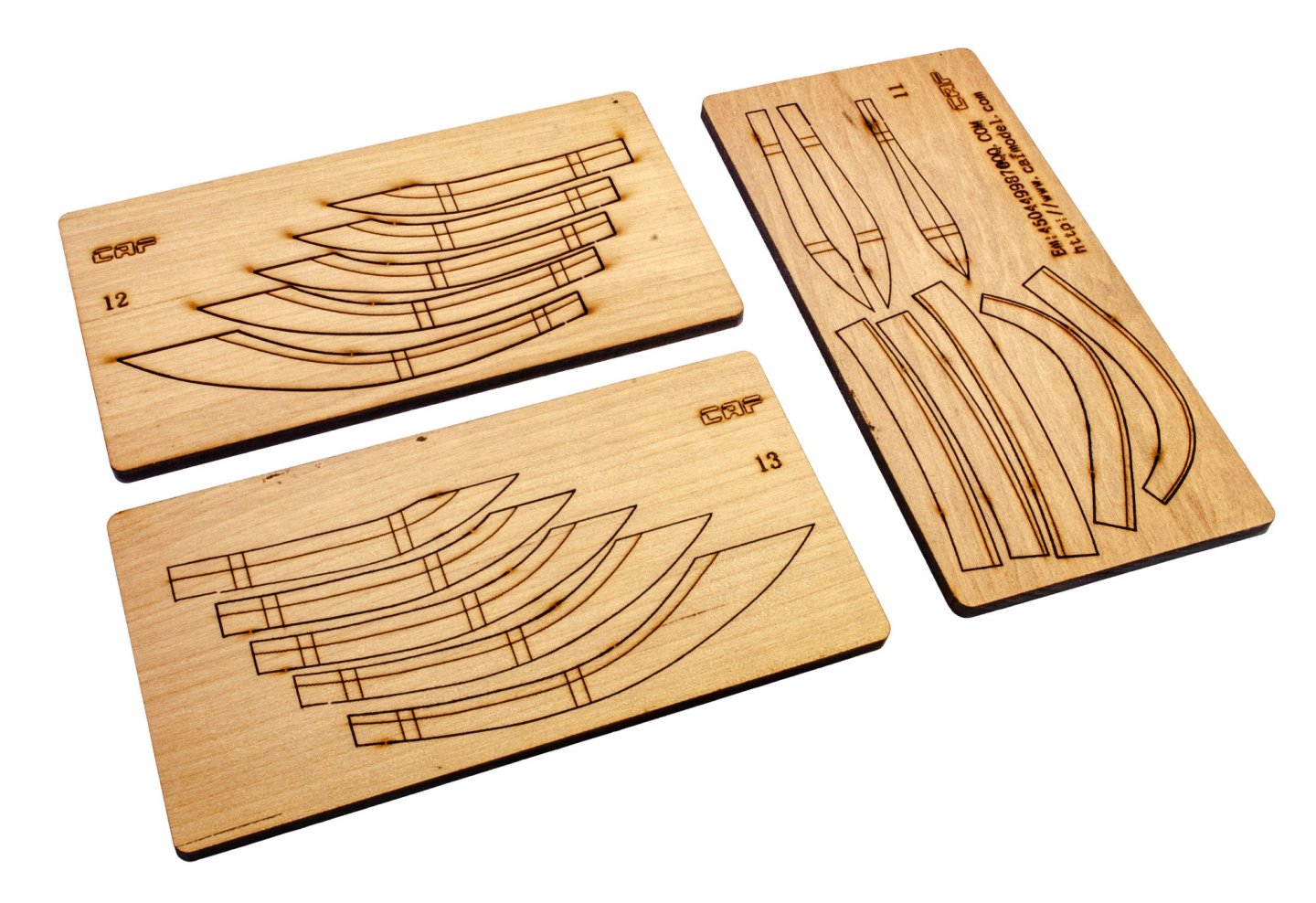
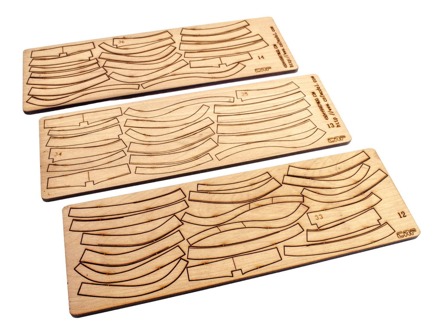
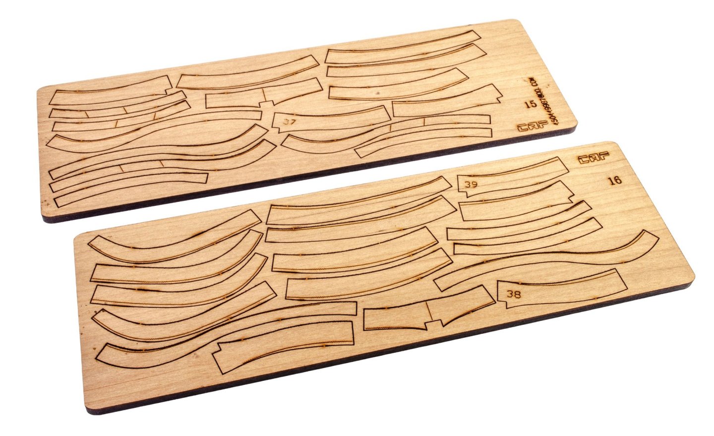
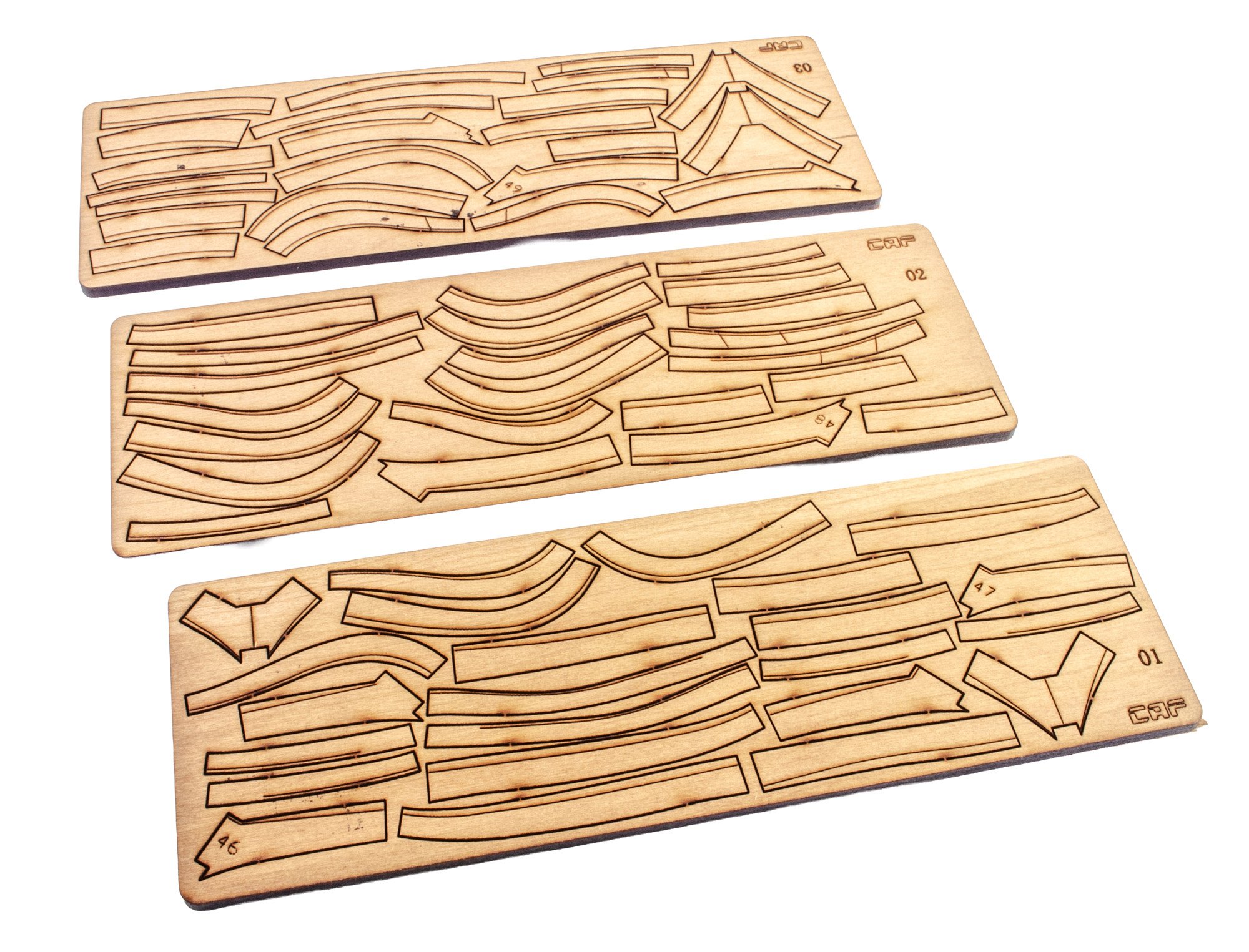
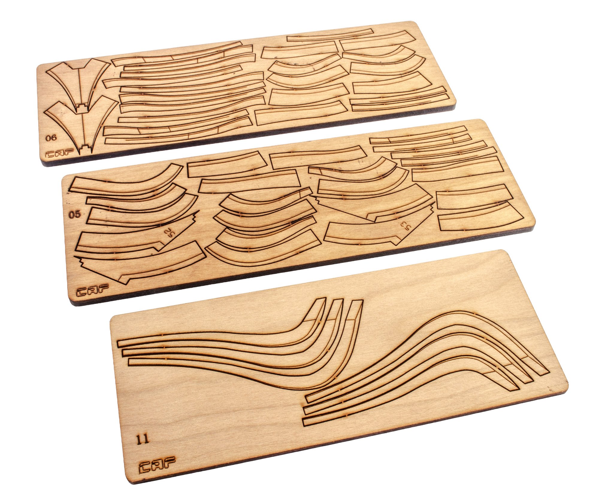
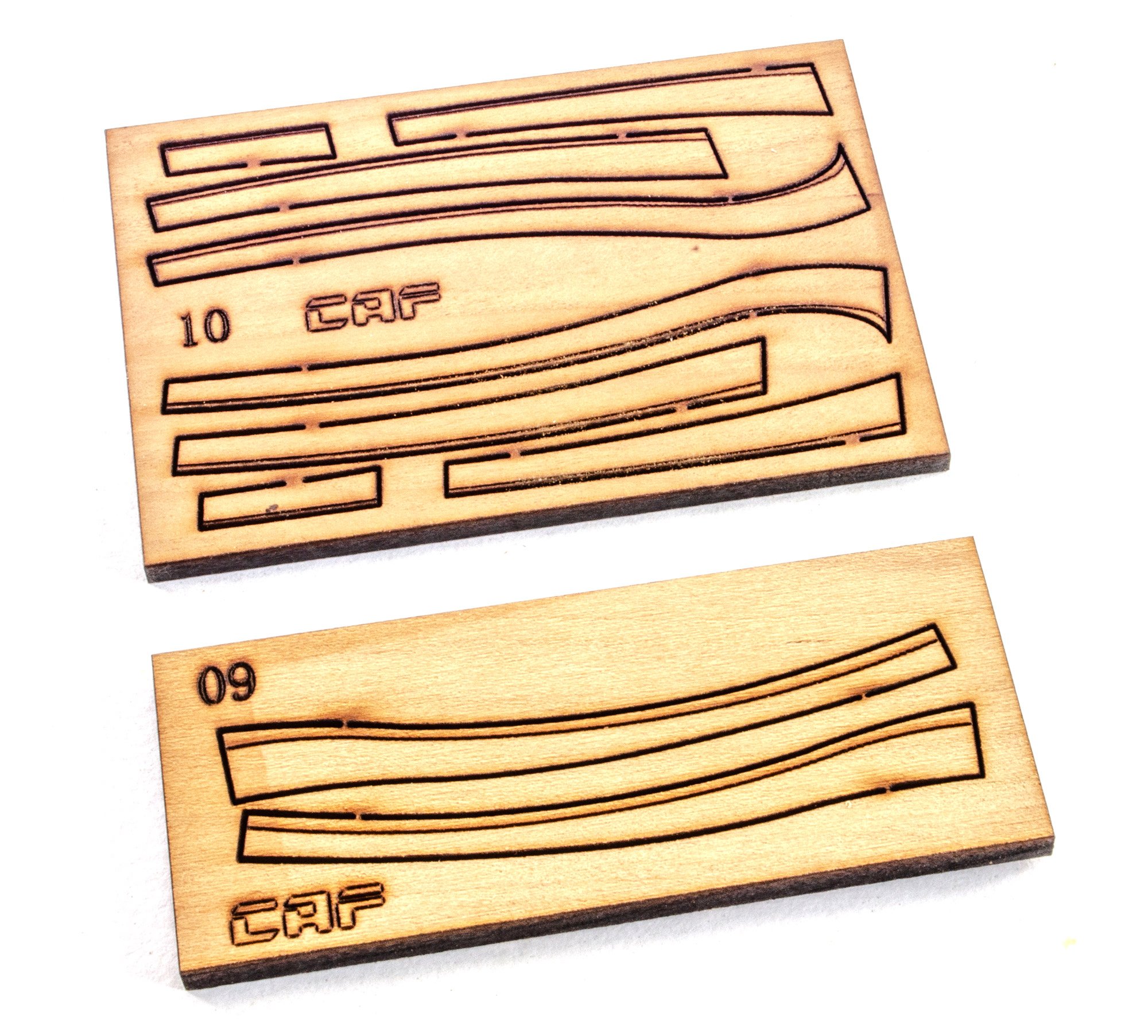
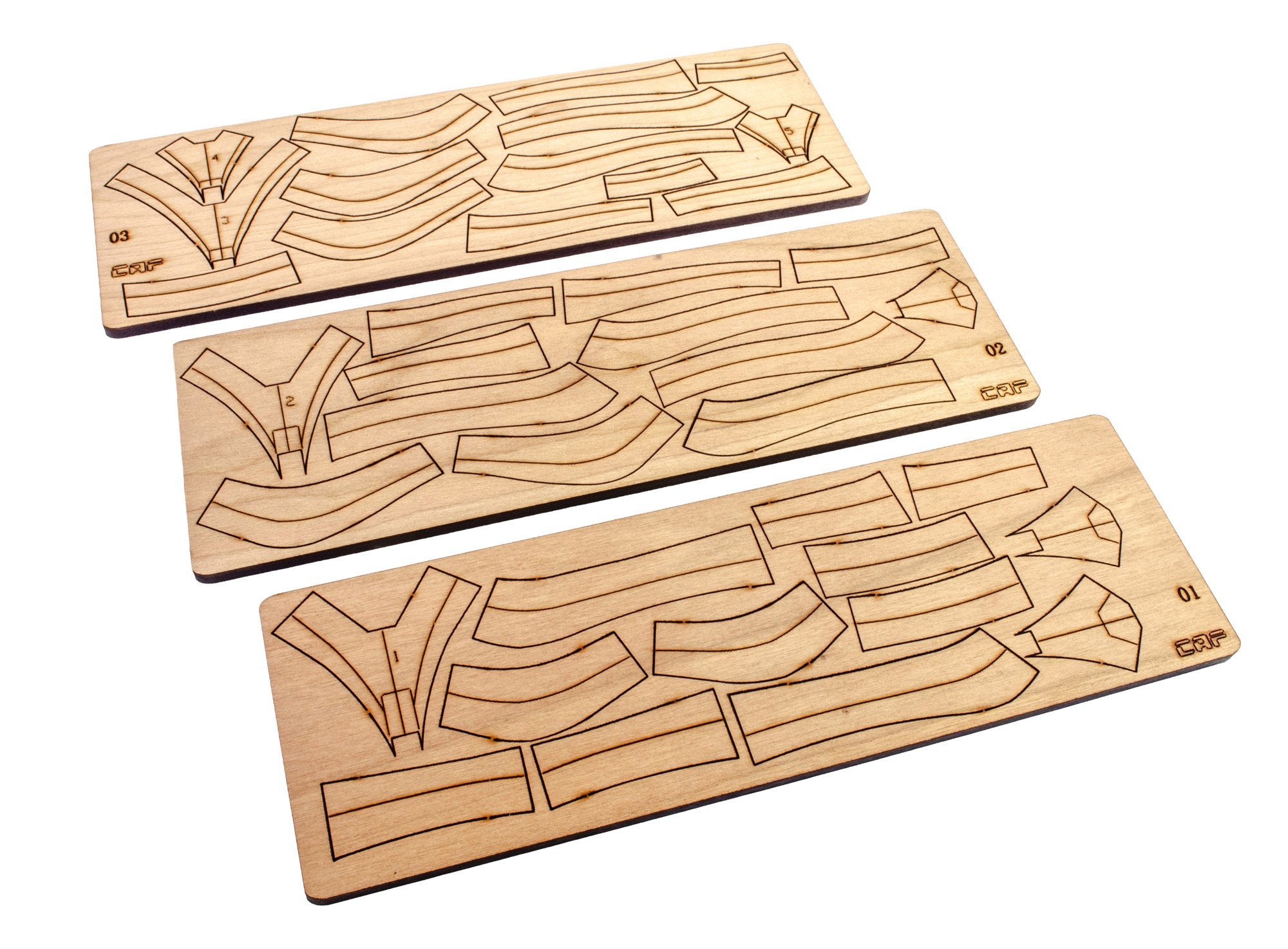
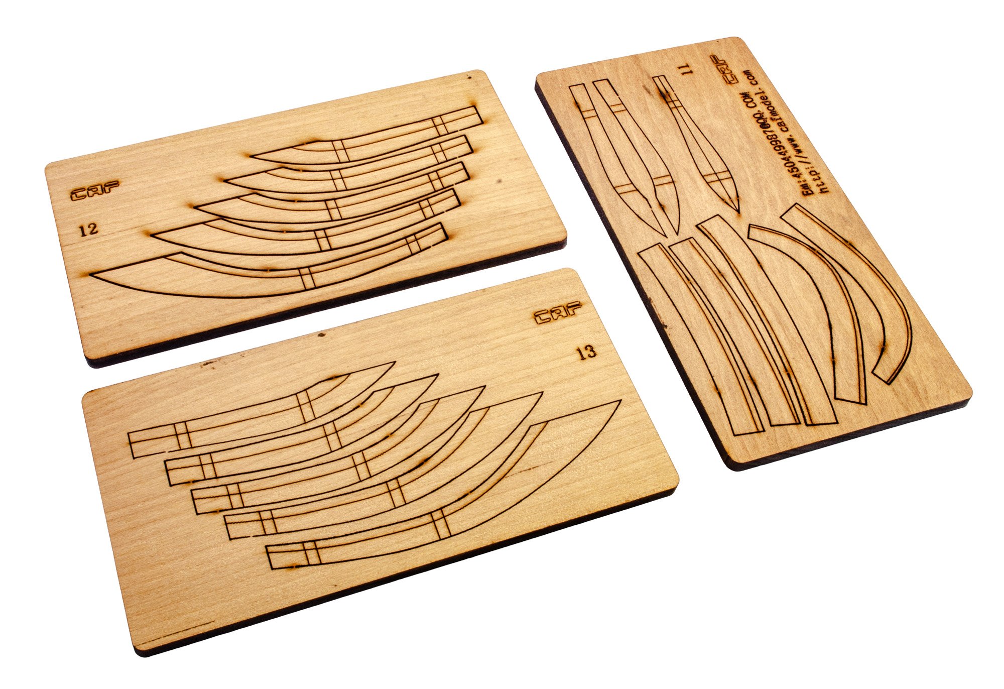
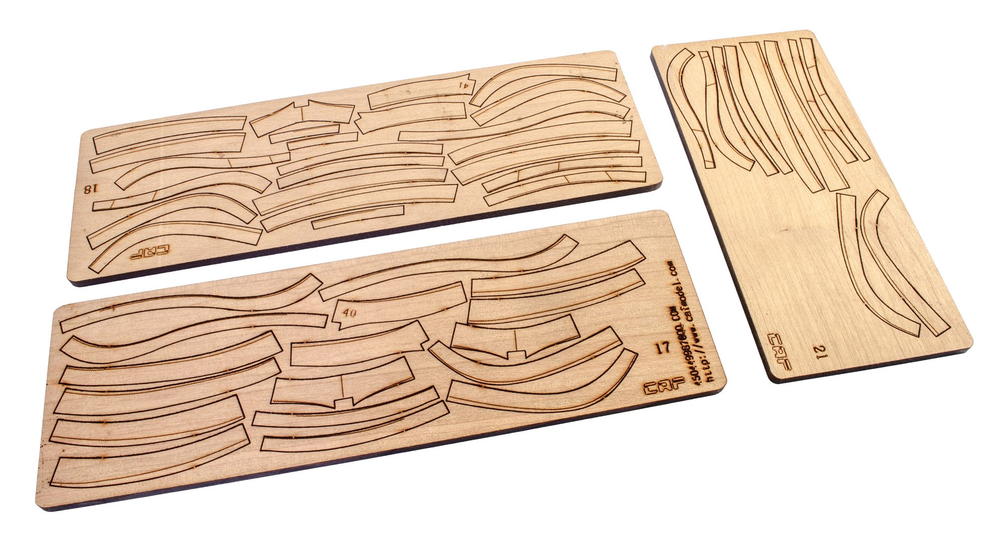
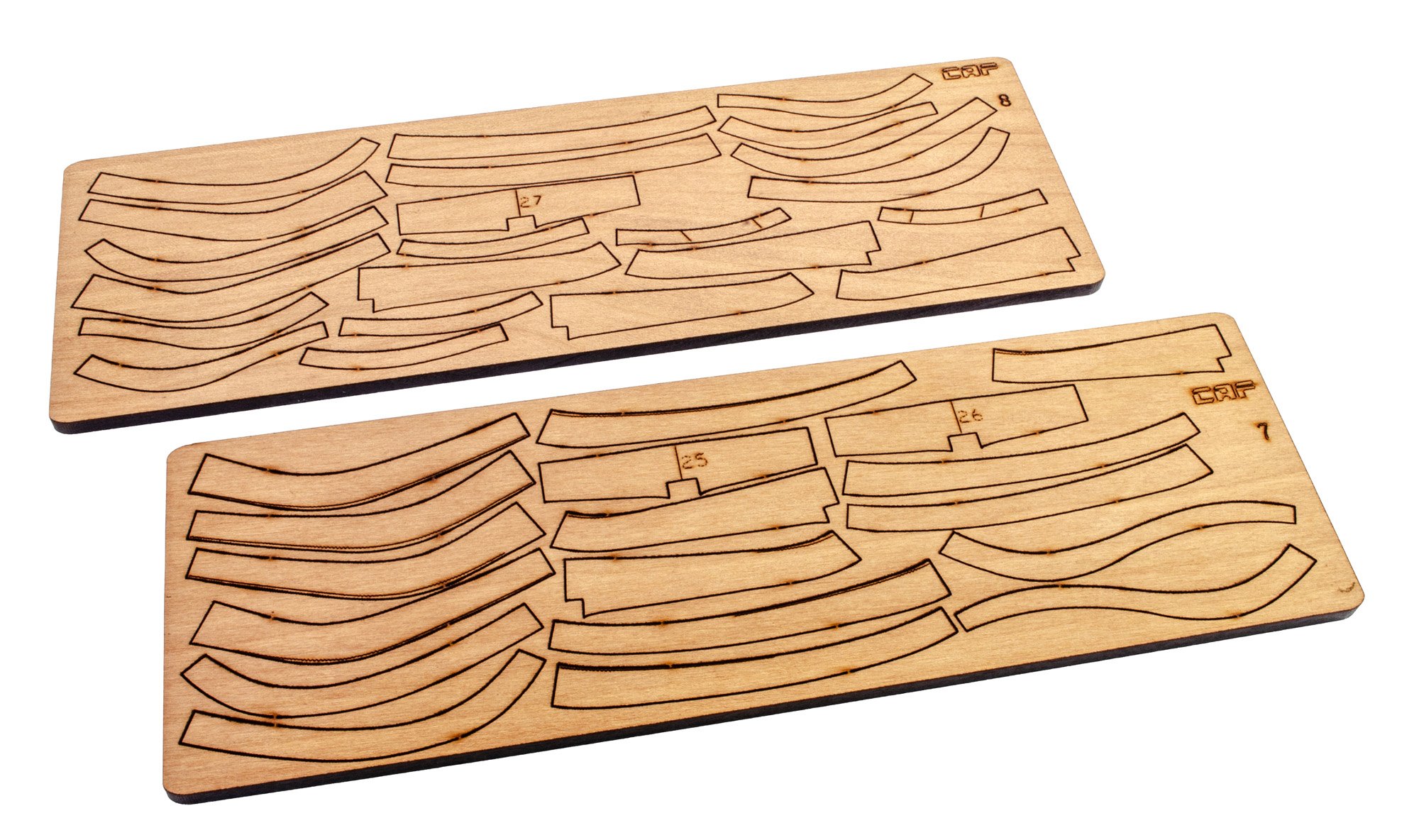
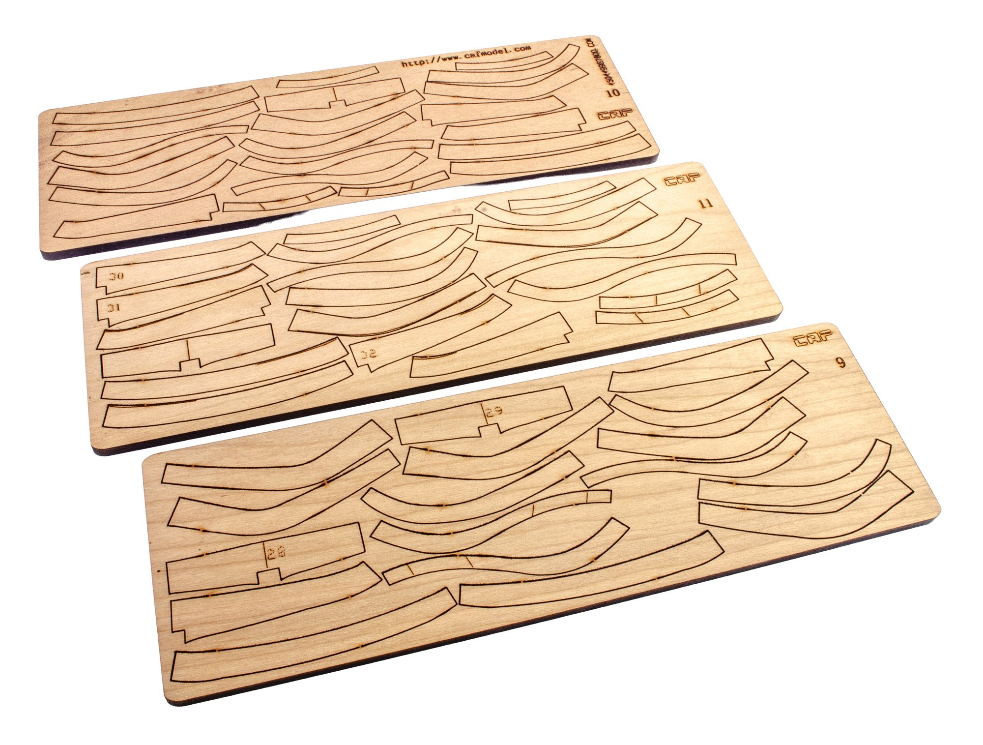
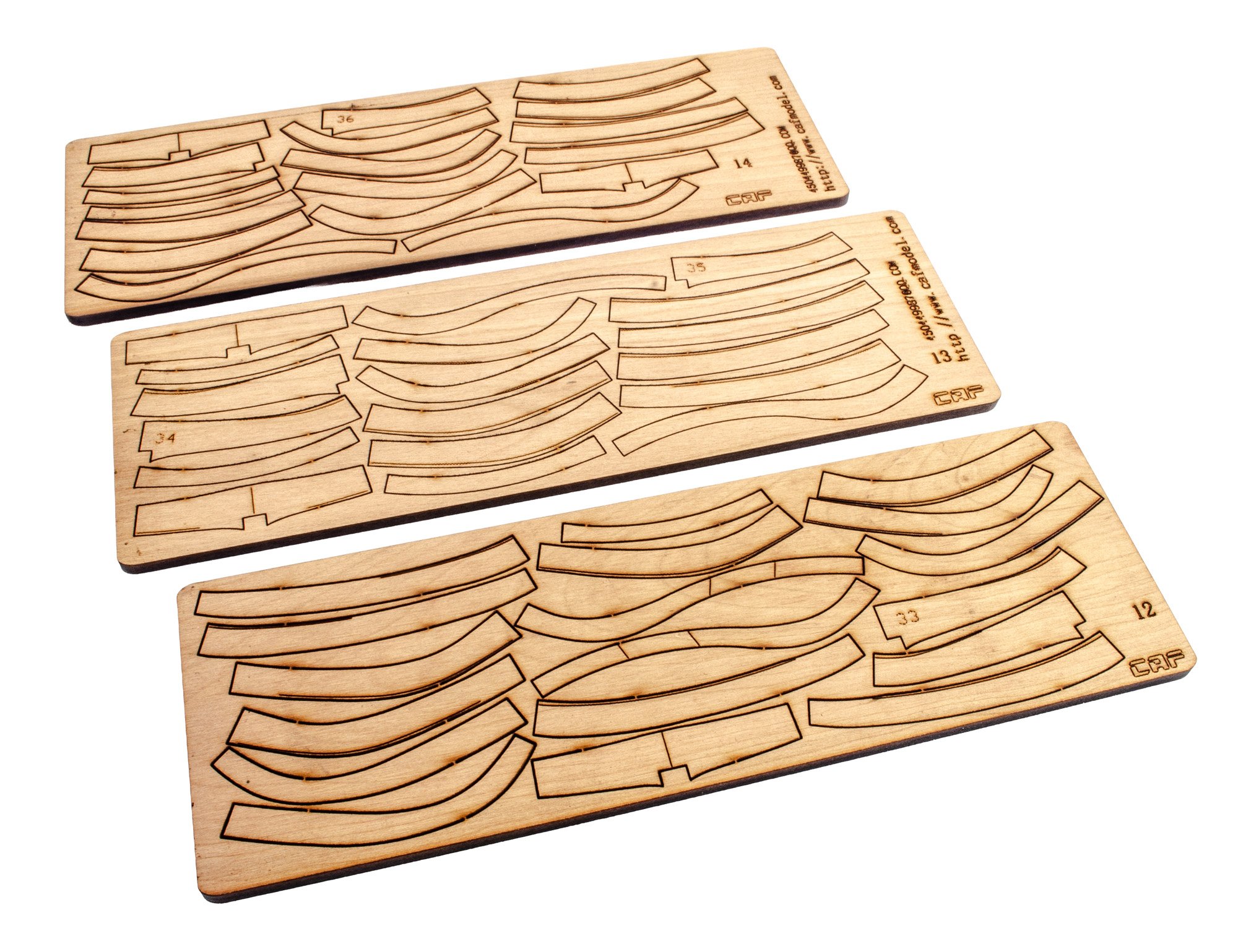
PART 1
Like the first sets in the La Renommée series, this contains many sheets (cherry wood) or frame parts. All sheets are laser cut and contain engraved lines which help with alignment and bevelling. There is some char/resin residue on the rear of the sheets, but this easily comes away with some minor sanding. Pack 1 contains three wrapped packets of parts. Numbering on these is shown in the manual, with each sheet having a reference number. There are no metal parts or fittings in this pack. All of this will come later.


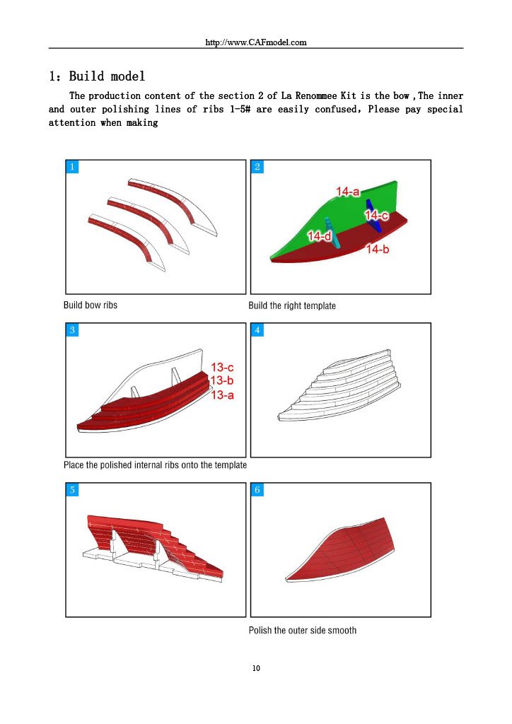
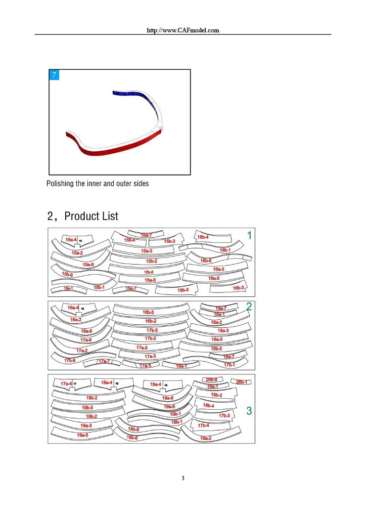
Instructions
The instruction booklet for this part is minimal as it merely shows the sheets and how the frames are built. There is also a large sheet over which the frames are assembled. Just remember to use some cellophane as a barrier so the parts don't stick to it.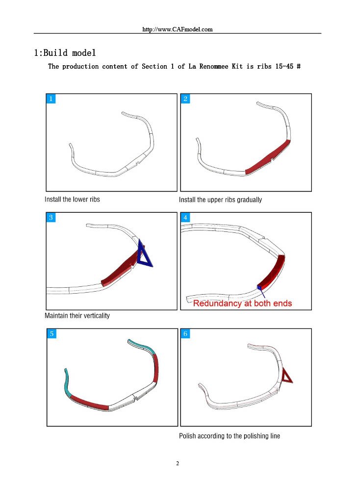
I will look at Part 2 in the next post.
- chris watton, GrandpaPhil and Ronald-V
-
3
-
Thanks for sharing that with us. Nice to see Tom with his finished project.
I'm just editing the first four stages but having a nightmare with my Mac and the latest Tahoe software which has laid my 2019 MacBook Pro waste.
- Paul Le Wol and Canute
-
2
-
57 minutes ago, The Bitter End said:
Could someone perhaps tie a link directly to the donate banner at the top of the page? It might make it easier for some users and a fraction less friction always helps...
I don't understand. You select your currency, add the amount and then just hit the Donate Now button.
I thought it was pretty easy 🤔

-
8 hours ago, JohnOz said:
Sorry guys, you need to look at the links
I did, and it works.

-
-
On 6/28/2025 at 7:19 PM, hmcarlin said:
James, you mention that you intend to review the La Renommee kit; any progress on that project? It's one that I've been considering, and would love to see your take on it!
In a week, I'll have all sections of the La Renommee kit. There are 7 individual set kits, and I'll be looking at each pack over the Christmas hols, onwards.
-
That is amazing work. Just beautiful.
-
24 minutes ago, Russ2025 said:
Thanks for the response Mike. I have been a victim of fraud previously with a fake PayPal account so it’s possible the card company have intervened. Definitely reluctant to use PayPal going forward.
Trust me, we don't use a fraudulent PayPal account for our donations application.
Thank you for ongoing attempt though. Much appreciated.
-
I love my Dremel stuff.
Just bought the 'Right Angle Attachment' with the same Amazon discount.

-
56 minutes ago, Thunder said:
I attended the IPMS model show at Telford this year and last year.
This is the VM plan for next year. Waiting to hear back confirmation.
-
39 minutes ago, Knocklouder said:
Sorry buddy , I got to learn how to read, I don't see the Rigging project anymore either, sorry,
Bob M.
I believe that's discontinued.
- Ryland Craze and Knocklouder
-
2
-
-
Let me check that out.
-
-
39 minutes ago, ubjs said:
This is the forum's default setting if you use cut and paste.No it's not.
- Ronald-V and Ryland Craze
-
1
-
 1
1
-
-
-
Moved to correct forum area.
-
8 hours ago, Pitan said:
Question.
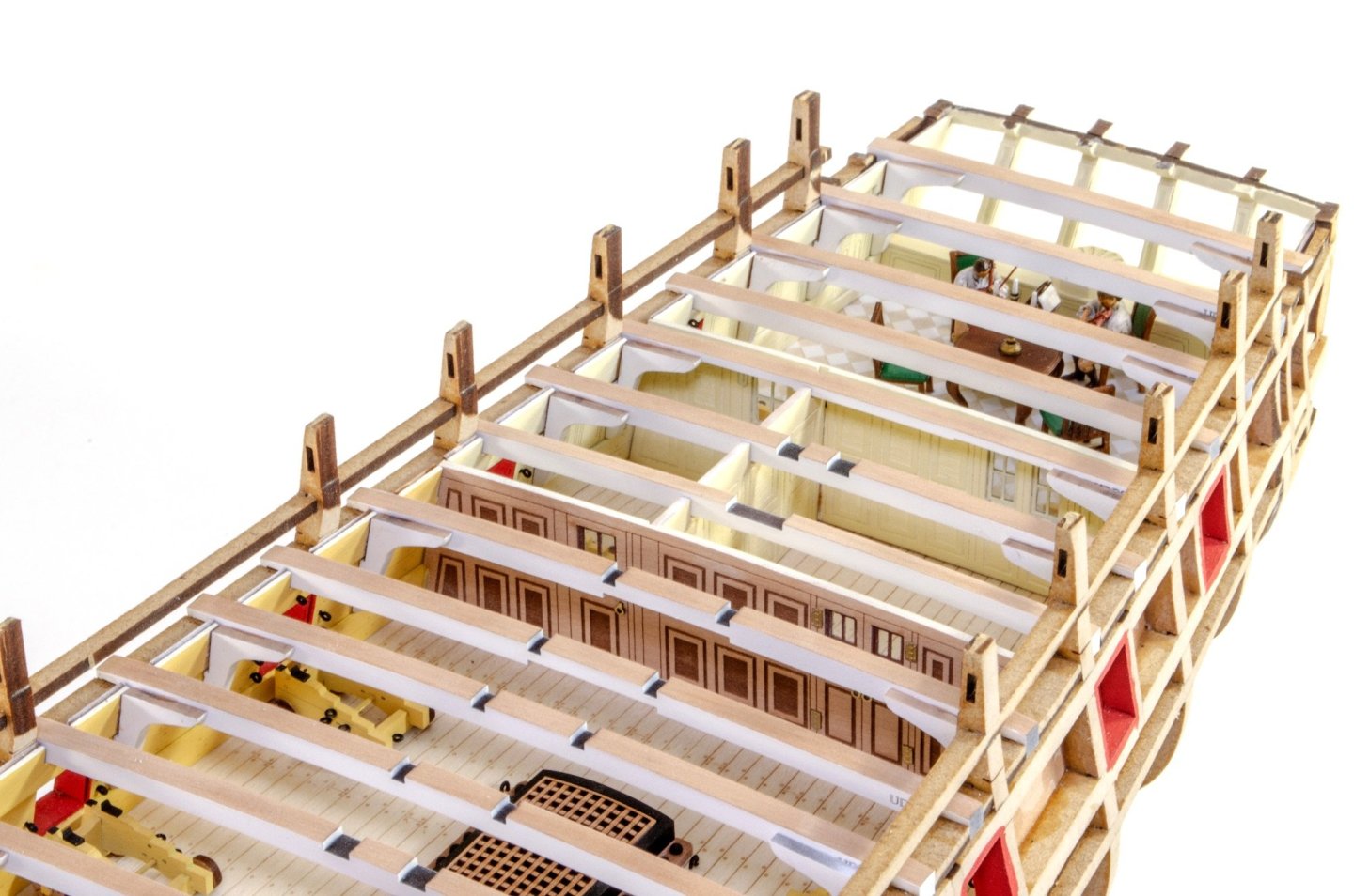
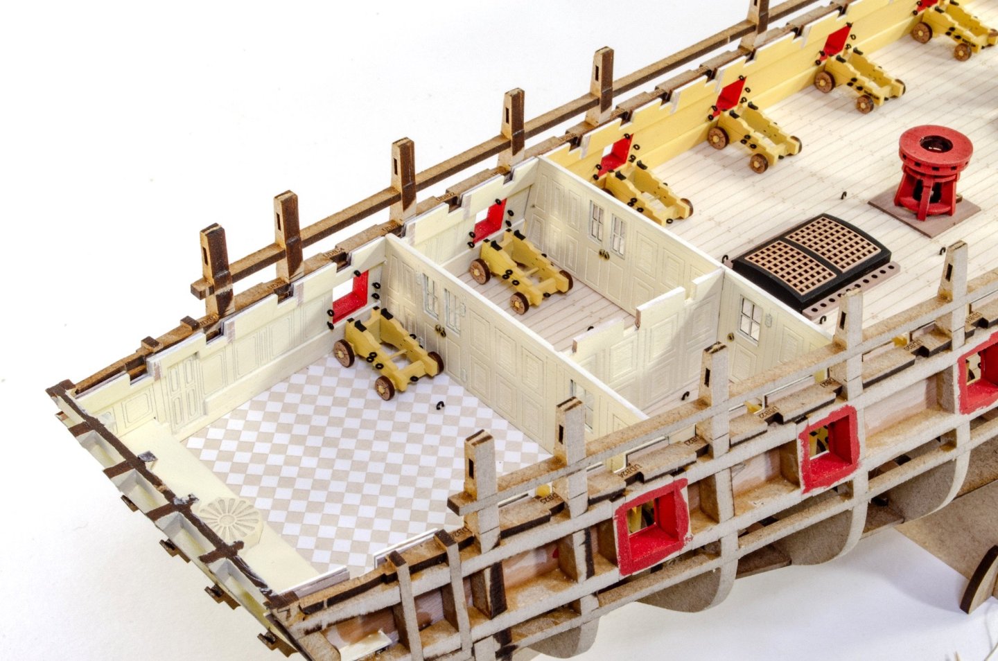
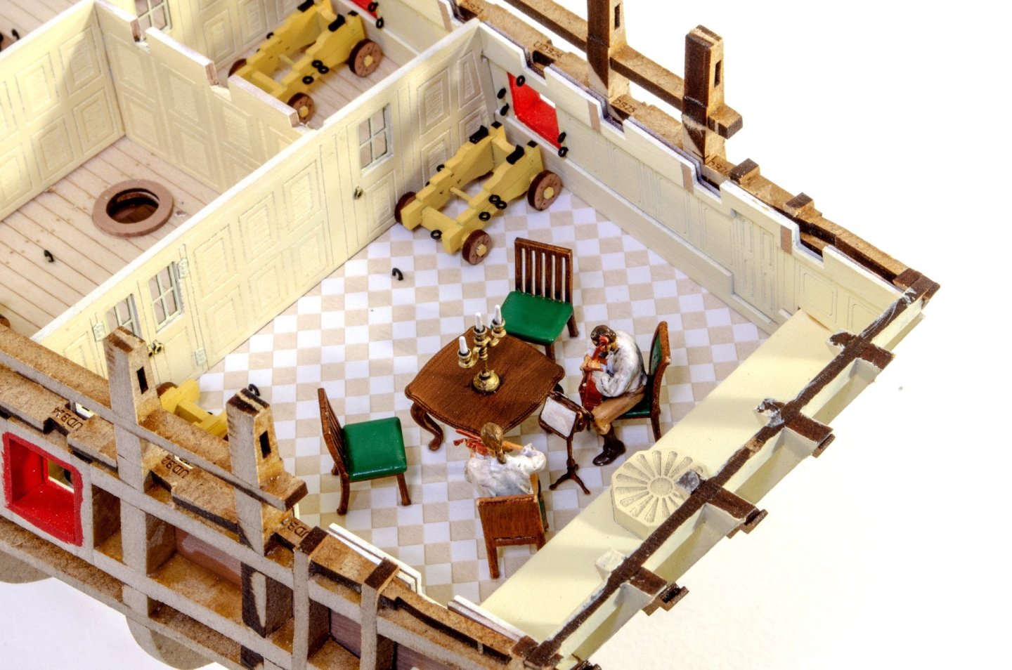
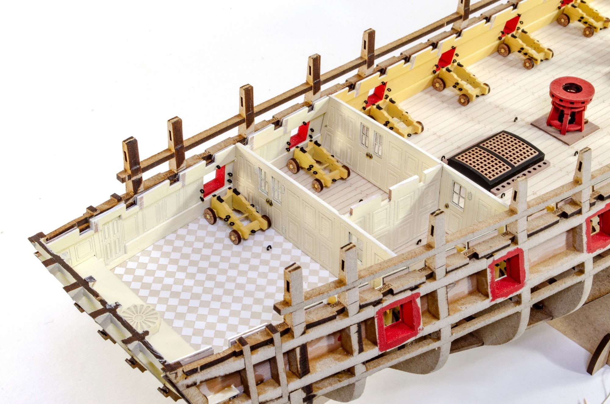
When not in action, would the gun carriages in the captain's cabin be stored facing fore or aft, rather than out to the side?
At the moment, they seem to be blocking access through the cabin doors while Aubrey and Maturin are relaxing with their music.Prob artistic licence, simply for display convention. A bit like the figures 😆
- uss frolick, Pitan, Canute and 1 other
-
4
-
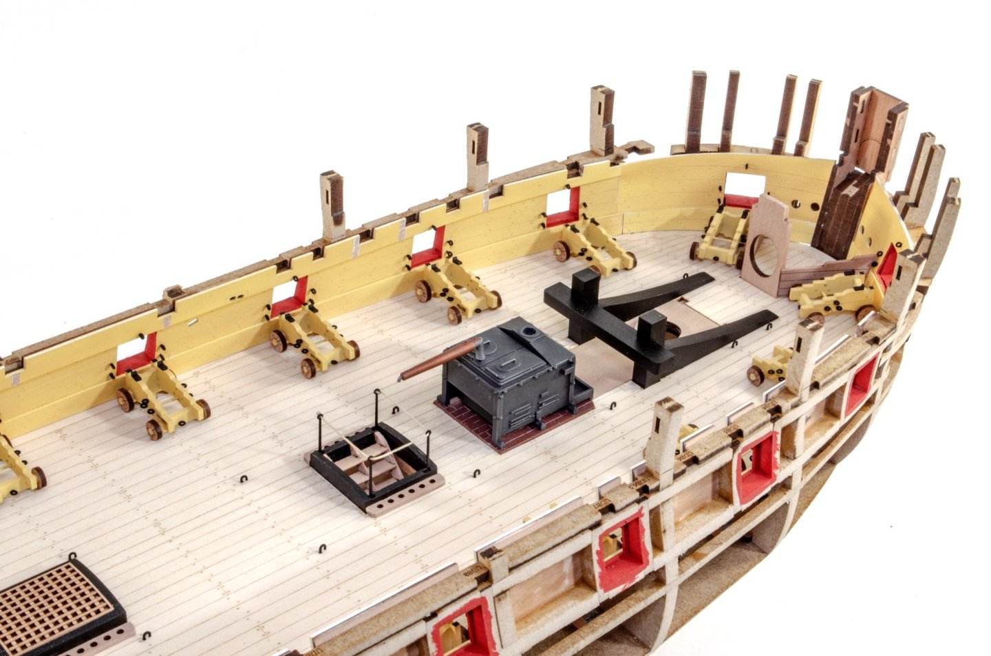
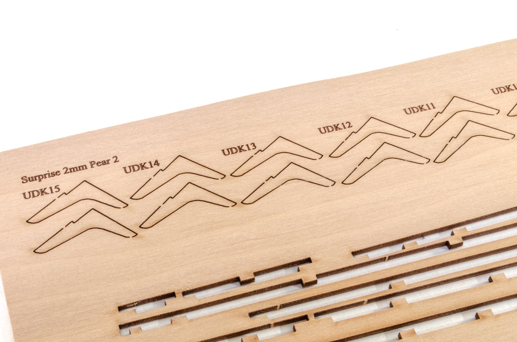
This brings Surprise almost up to date as I've begun to plank the hull.
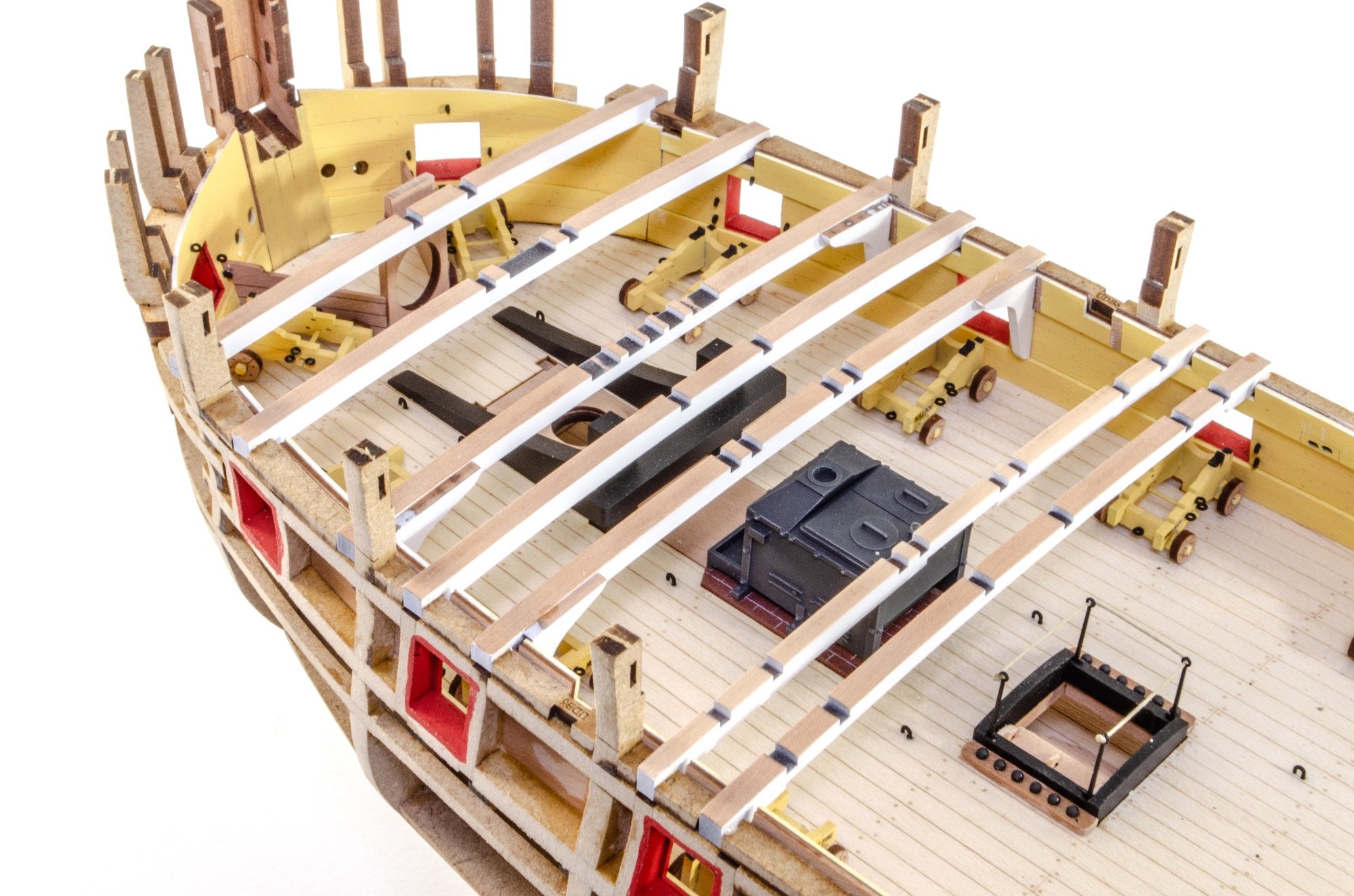
All deck beams are cut from 4mm pear except for two in 3mm pear. All beams have laser char removed from the upper surface which is then masked before the rest of the timber is sprayed in white paint. I used Tamiya Fine Surface Primer. The beam knees are also sprayed in the same colour. The knees are specific to individual locations too.


Mast and capstan locations are bolstered with reinforcement parts.
And here is what Surprise looks like at this stage. Hope you like her.


-
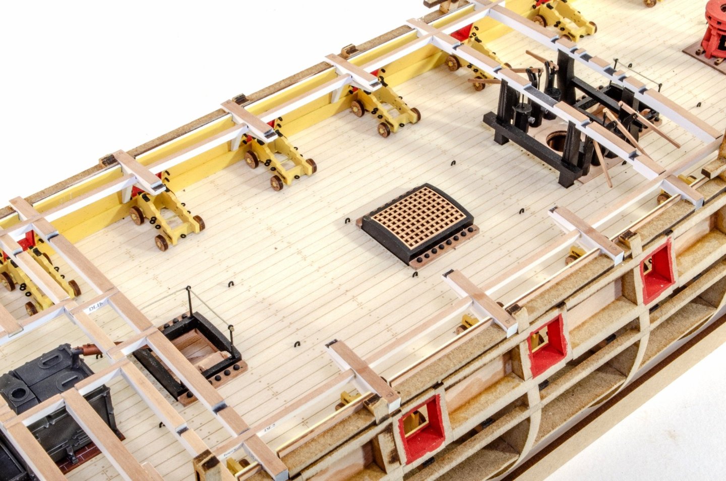
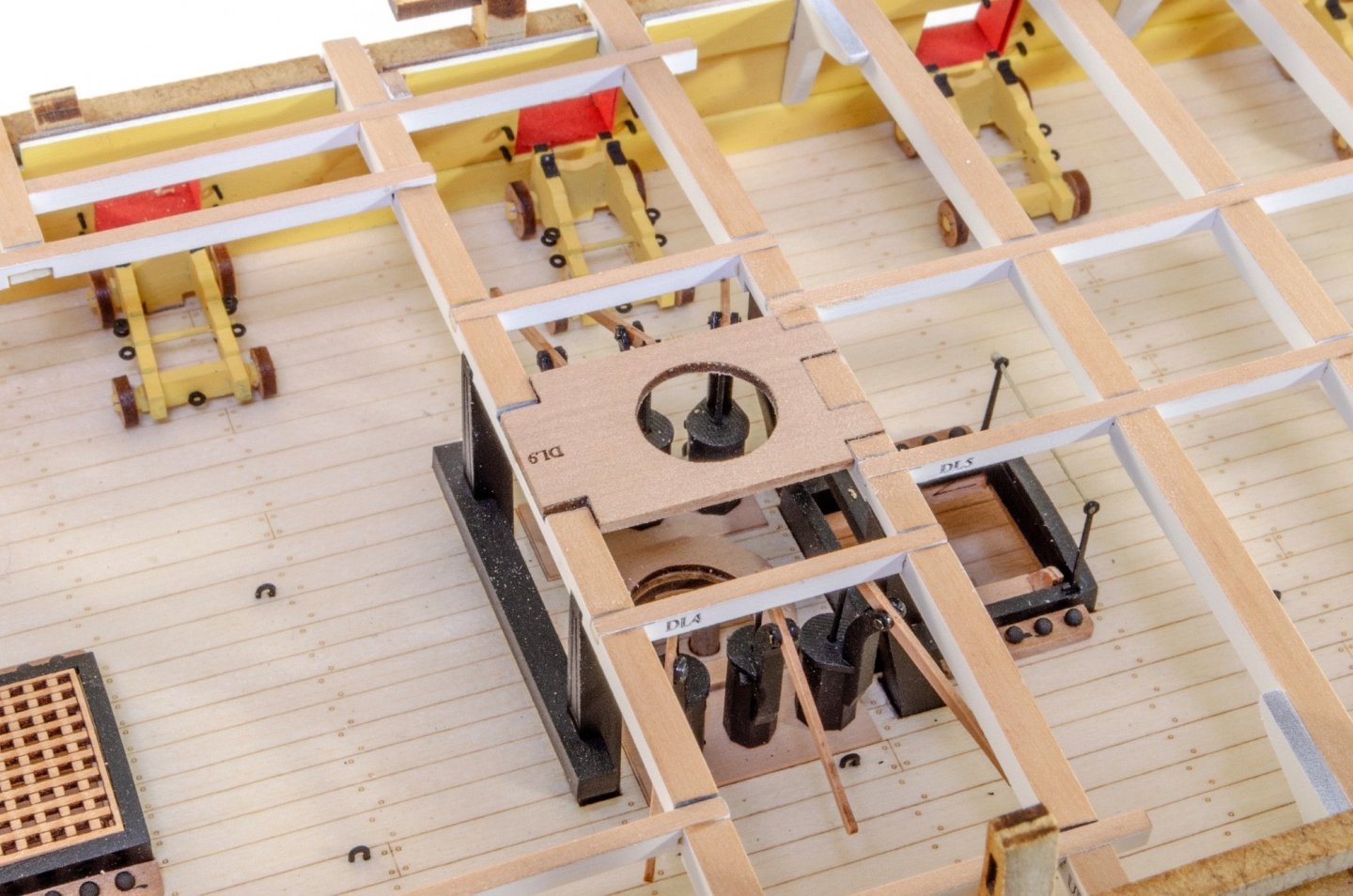
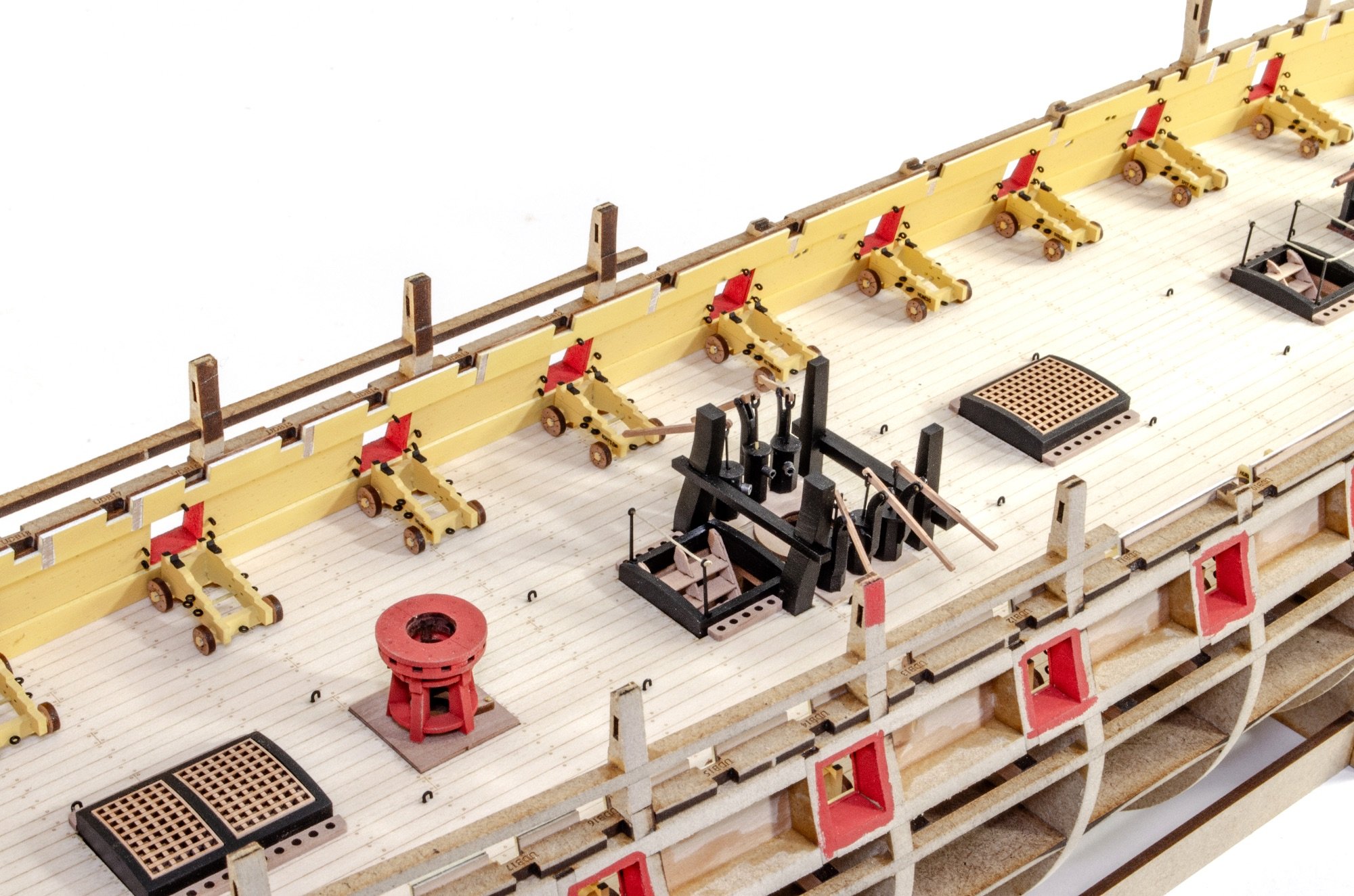
I did promise another update, so here's a small one, but with some definitive changes.
In these photos, you'll see the gun carriages are now fitted. As previously mentioned, these have tabs which fit into slots around the deck edges, meaning the guns will always be perfectly positioned. The only ports not slotted are the bow chasers as they are optional. Whilst the inner port exists as shown, they will be blanked off on the external surface, with an option to cut them out yourself. Port lids are included, should you wish to fit these. There are also 3 spare carts, so two can be used here, should you wish. You'd just need to remove the cart tabs. The guns are also fitted last, after the model is very much complete, otherwise.

I know a few people wanted to see these last photos. To be honest, I'm not great at figure painting, so I've done my best here. I used acrylics for the figures as I didn't have oils to suit. The table, chairs and music stand are mostly in oils, over a sand coloured acrylic paint.
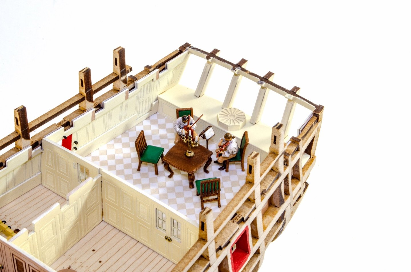
Give me a couple more days and I'll do another update.


La Renommee Longboat by hmcarlin - CAFModel - 1:48
in - Kit build logs for subjects built from 1501 - 1750
Posted
Any movement on this?