James H
-
Posts
5,517 -
Joined
-
Last visited
Content Type
Profiles
Forums
Gallery
Events
Everything posted by James H
-
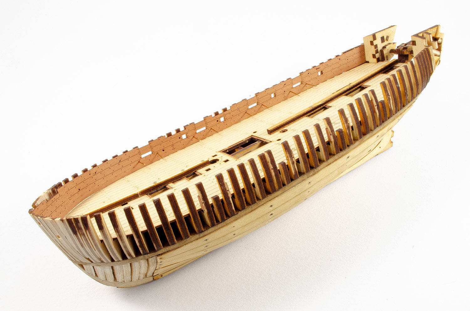
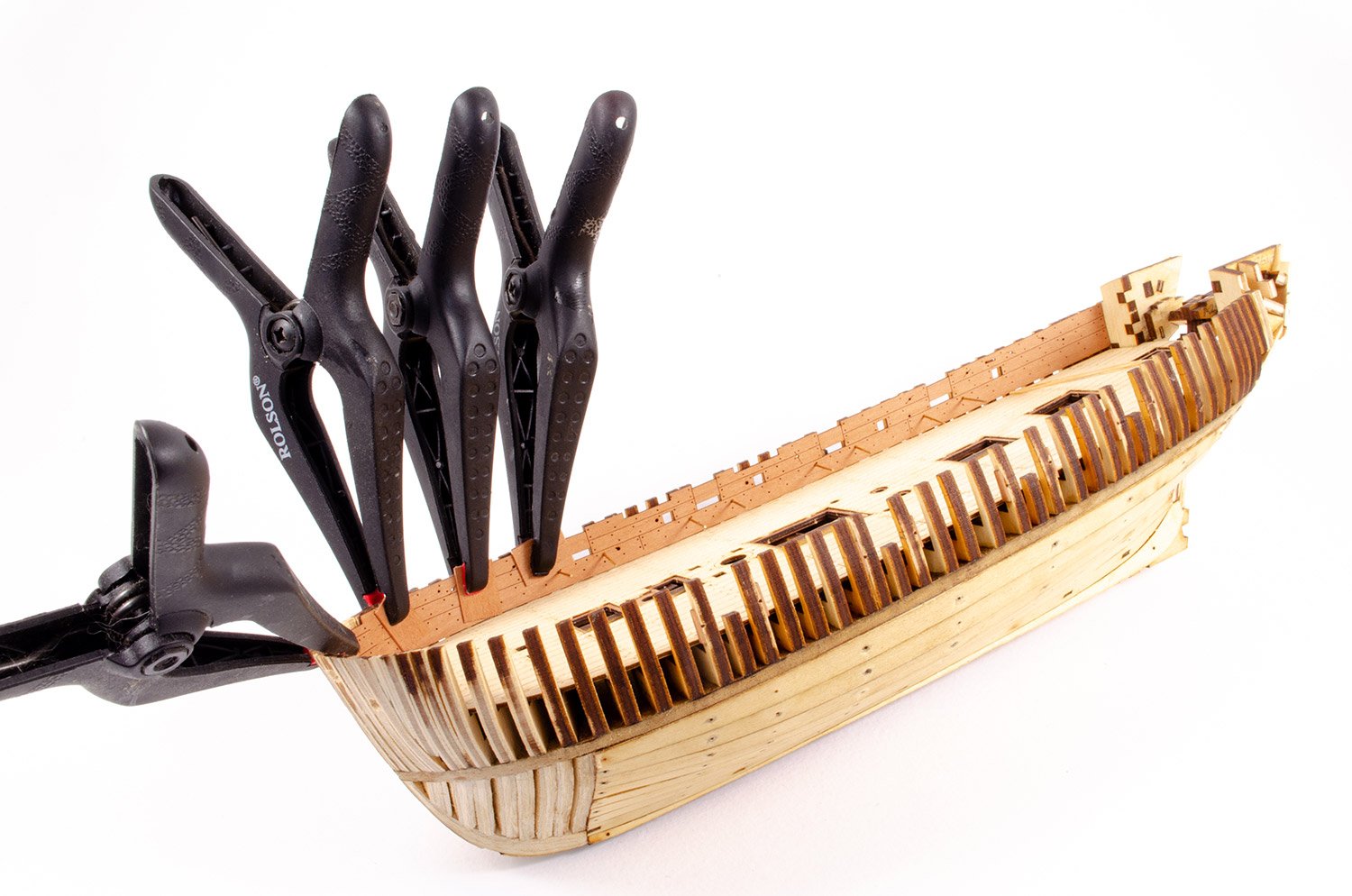
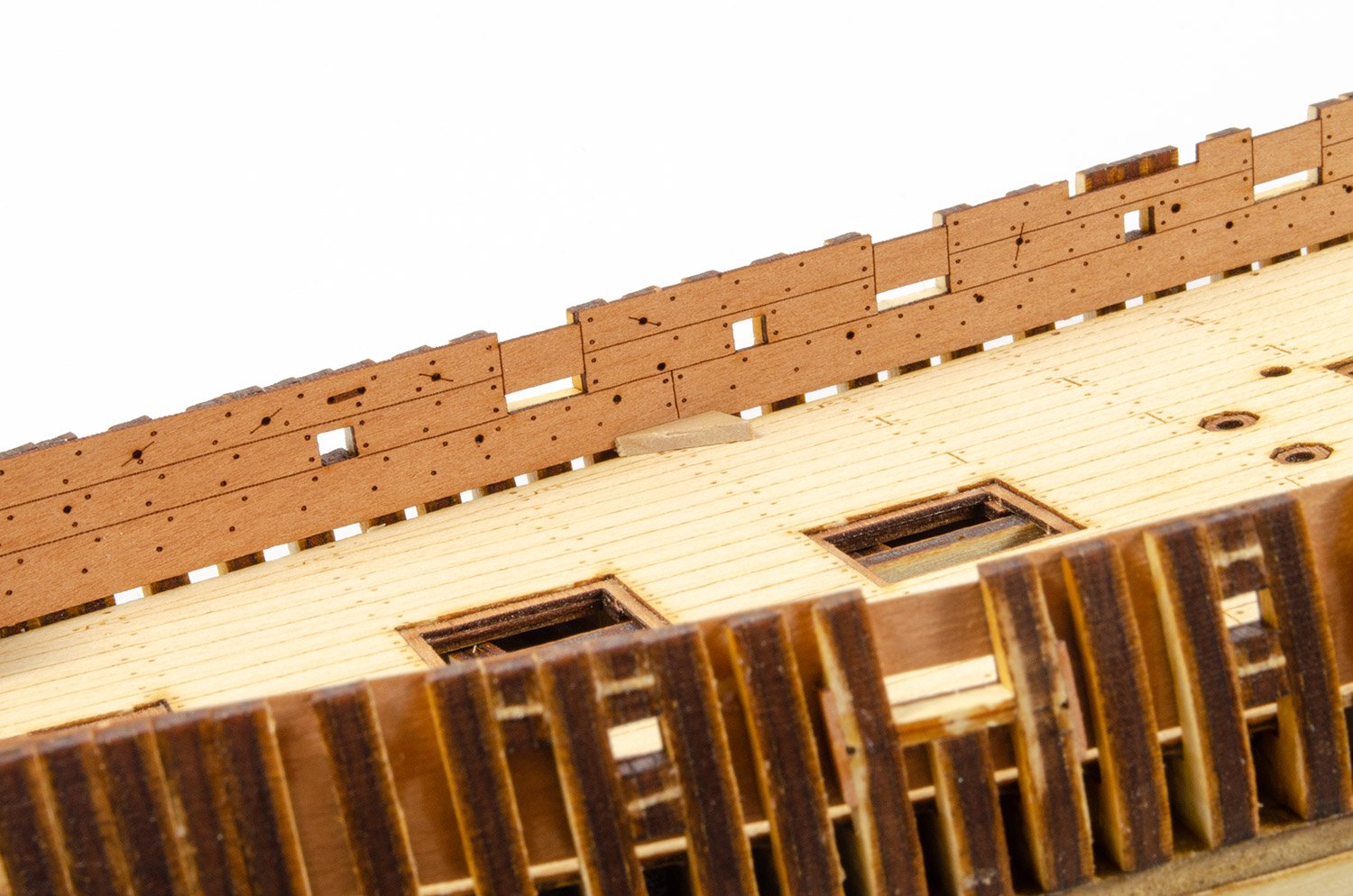
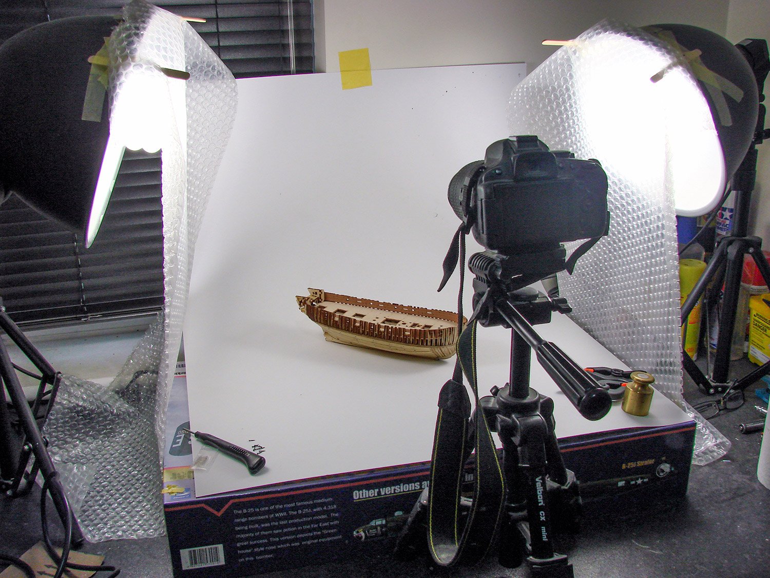
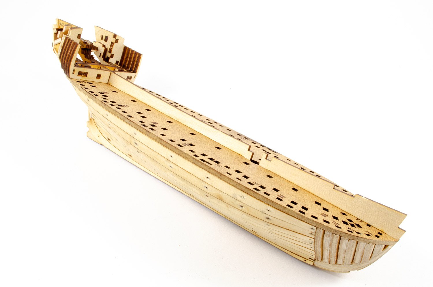
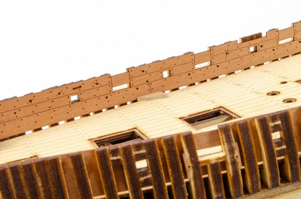
 Only a small update this time before I sand the hull and prepare it for the pear planking. First of all, I glue the deck in place, but only down the centreline of the hull. The edges are left loose for the moment. I'll explain that in a moment. With the deck installed, the inner pear veneer bulwarks are installed. To align the bulwarks, some brass pins are inserted through the bulkheads that we saw modified in the last post. I gradually worked my way around the frames, gluing the bulwark as I went. Small pieces of scrap pear veneer are used to protect the bulwark from the jaws of the clamps. with the bulwarks in place and securely glued using Titebond, cocktail sticks are slipped under the bulwark, pushing the edges of the deck down so I had a nice and even gap all of the way along the bulwark. This is just under 1mm. I had to add a little shim in a few places under the deck, between the deck and the hull frames, but not too many. A scrap piece of the material from the waterways ply sheet was tested to make sure it would cover the gap. Hopefully, there'll be minimum fuss when the waterway is fitted. Very happy with this so far. Ok, @Peta_V, here's a photo of how I do my pictures. This is quite a small area which I primarily used for photographing 1:32 model aircraft, and I will need to expand when I start the Amati 1:64 HMS Victory build in a couple of months. I use two Tri-phosphor Spiral CFL Daylight Balanced Pure White Light Bulb with 5500K Color Temperature (85W) for my lighting, diffused with bubble-wrap. The card is A0 in size and described as 'Ice White' which is perfect for sorting my white balance. The camera is a Nikon D5100 DSLR, used with a 18-55mm VR Lens. I sometimes use my 35mm lens, but I've no real need for most work. Camera is set to Manual mode. Photos are then processed through Adobe Lightroom and Photoshop.


- 30 replies
-
- 19
-

-
- master korabel
- avos
- (and 1 more)
-
Those cannon look superb.
-
Chris already answered the first one, and that was because it was what he was asked to do. No one knows why they aren't releasing new designs. You could email and ask them I suppose.
-
The current position is that I need to build Amati another Victory for their new style of instruction manual. I'll have the parts around Sept/Oct. From there, I'll do a build log (of sorts) here and as soon as complete (minus masts as those are done via drawings), Amati will compile their photo manual from what I send them (pics and text). They'll need to get their PE and laser cutting made, plus boxes, fittings, plans etc. Then you'll see a release. I presume that they will be ordering in their materials in the latter stages of the build, once they know no changes need to be made. NOTE: Renamed the topic title to reflect the discussion on the Amati kit.
-
What oil are you using? Will this not cause the grain to raise?
-
I'll take a photo of what I use to create the pictures when I do my next update.
- 30 replies
-
- 6
-
-
- master korabel
- avos
- (and 1 more)
-
I'm afraid my magazine photo style dies hard with me. 📖 My apologies. Your build is what is inspiring my work!
- 30 replies
-
- 7
-
-
- master korabel
- avos
- (and 1 more)
-
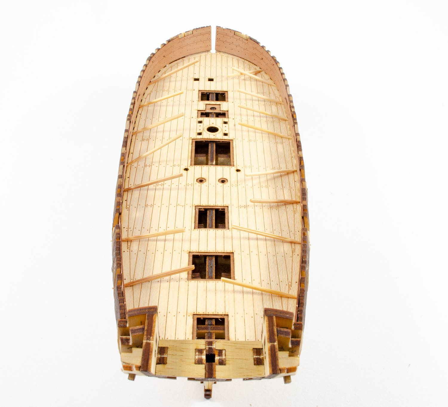
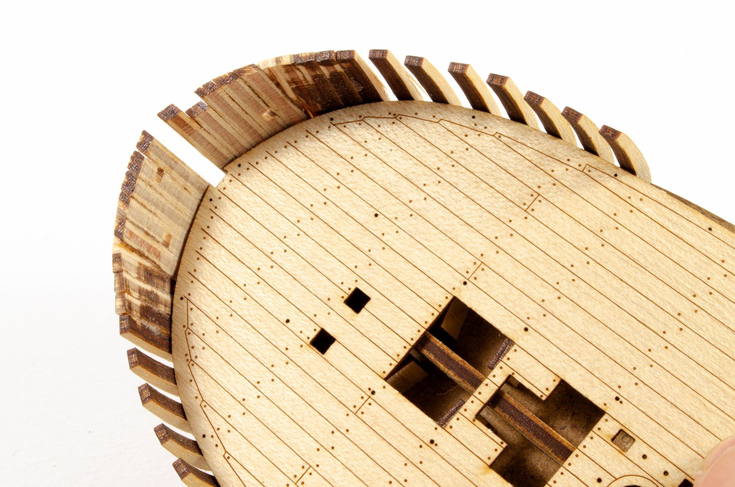
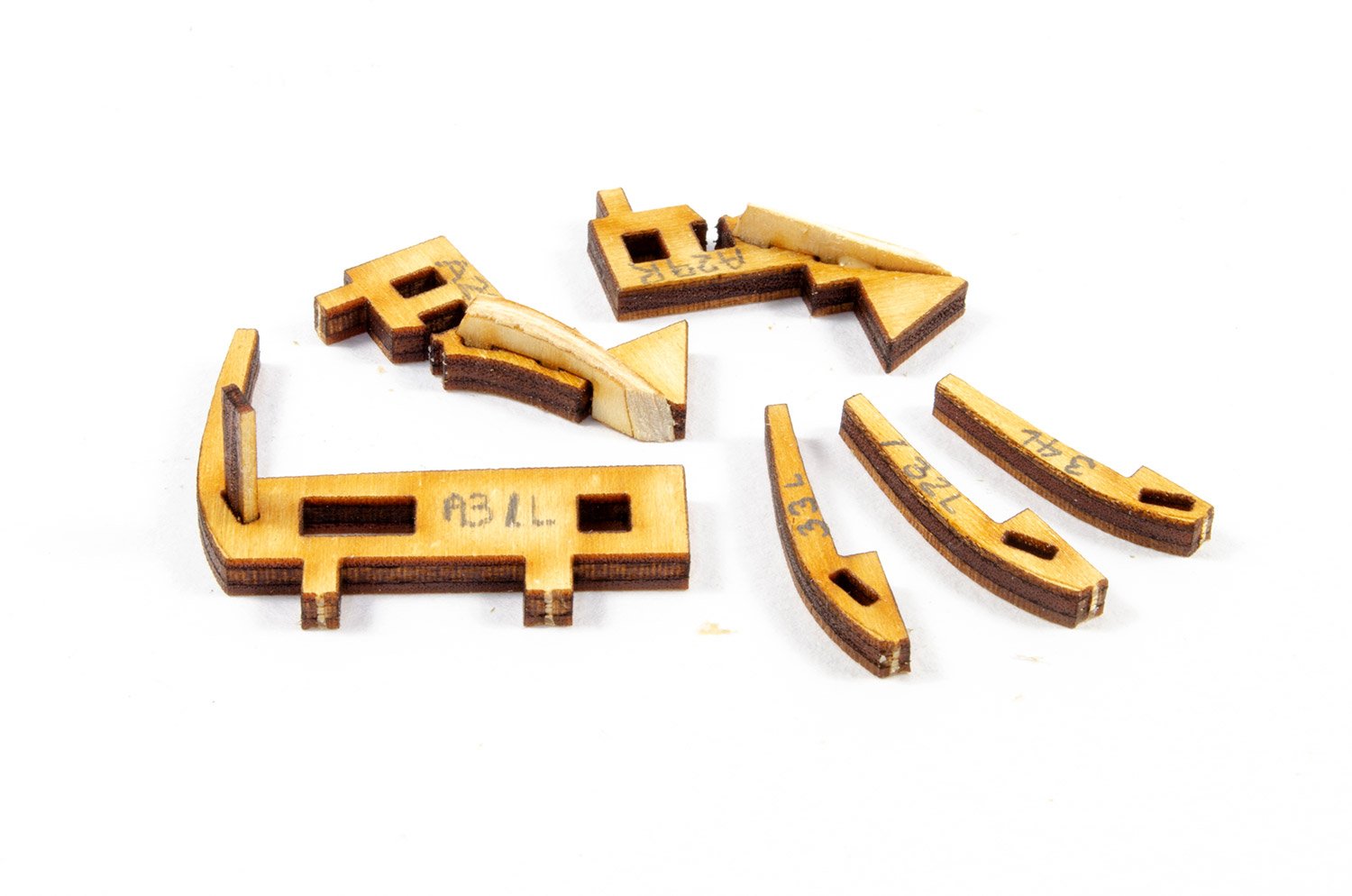
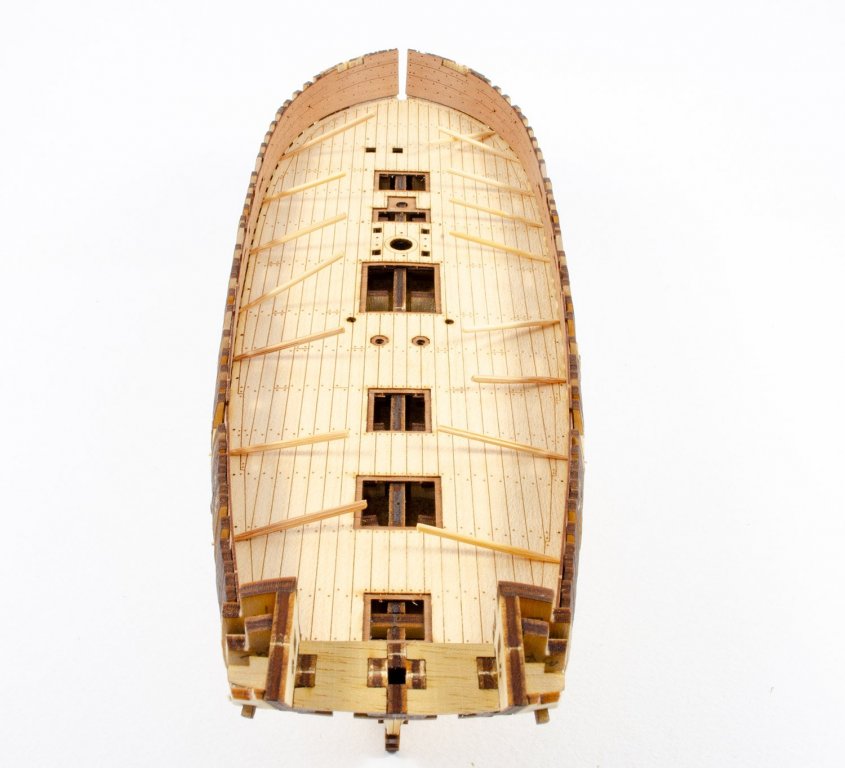
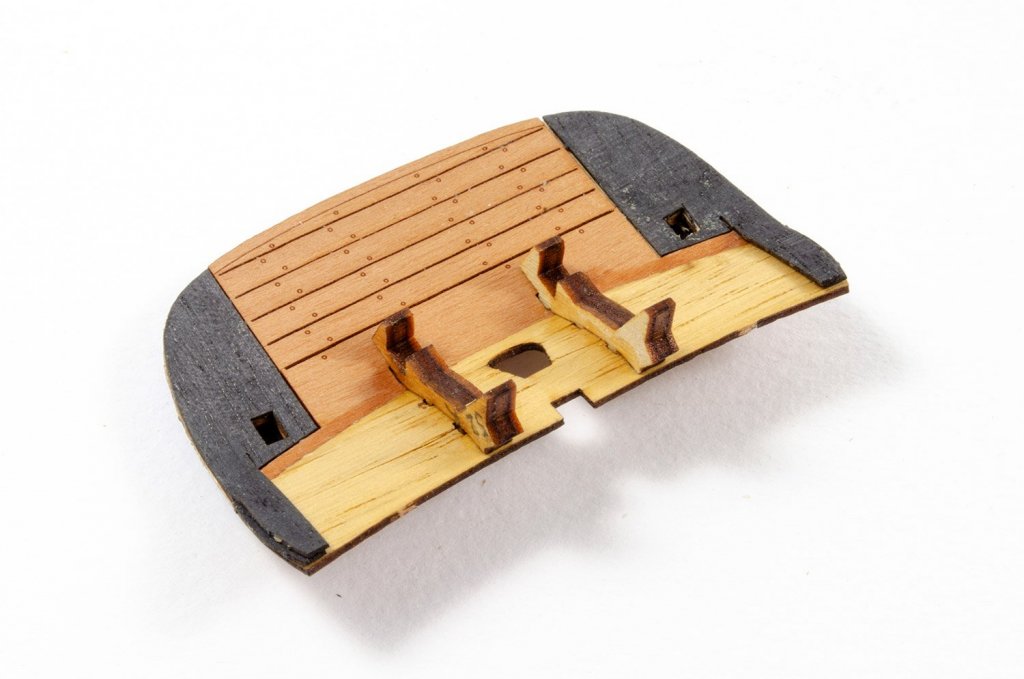
I've had a couple of days away from the bench for various reasons, so it was good to get back and work on this lovely little kit again. As per instruction, the laser-printed deck was test fitted to the hull to check the fit in the inner bow area. I was pretty pleased with this. On frame on the port side helped create a small gap but that will be hidden when the inner bulwarks are fitted, and of course, there are the waterways to install also. Some port and starboard frames need to have a slot added to them to accommodate a 0.6mm brass pin. These are created with a fine razor saw and a scalpel knife. Once made, a small piece of pear is added to them and when dry, a 0.6mm drill bit is passed through to ensure clean passage for the pin. These pins will help to locate the inner bulwarks and it's important that the frames are matched up against the bulwarks as they are being added. I opted NOT to add the pear gun port linings as I would lose the laser-engraved marks on those faces. I could've done it, but it didn't seem to be really worth that extra effort. At this point, I do a little work on the deck. First, some pear-faced ply parts are used to line the deck apertures. These sit roughly 0.4mm lower than thee decl surface. Some sanding was needed to make sure the ply parts fit into the holes. CA was used to glue these and then dry, the underside of the parts were sanded flush with the deck underside before some reinforcement parts were added. Lastly, two beams were added which gives the deck the required camber. More soon...


- 30 replies
-
- 21
-
-
- master korabel
- avos
- (and 1 more)
-
A fair summary. You could pull it in at just over 4ft long if you were to build the hull as an Admiralty-style model with all framing on show. I think that's how I would do it, or I'd need a much bigger house.
- 13 replies
-
- 5
-
-
- plans
- monografie
- (and 1 more)
-
Never seen this kit before.
-
Welcome to MSW... ...and semi-named after one of rock's best characters! Looking forward to seeing you whittle some wood here on MSW.
-
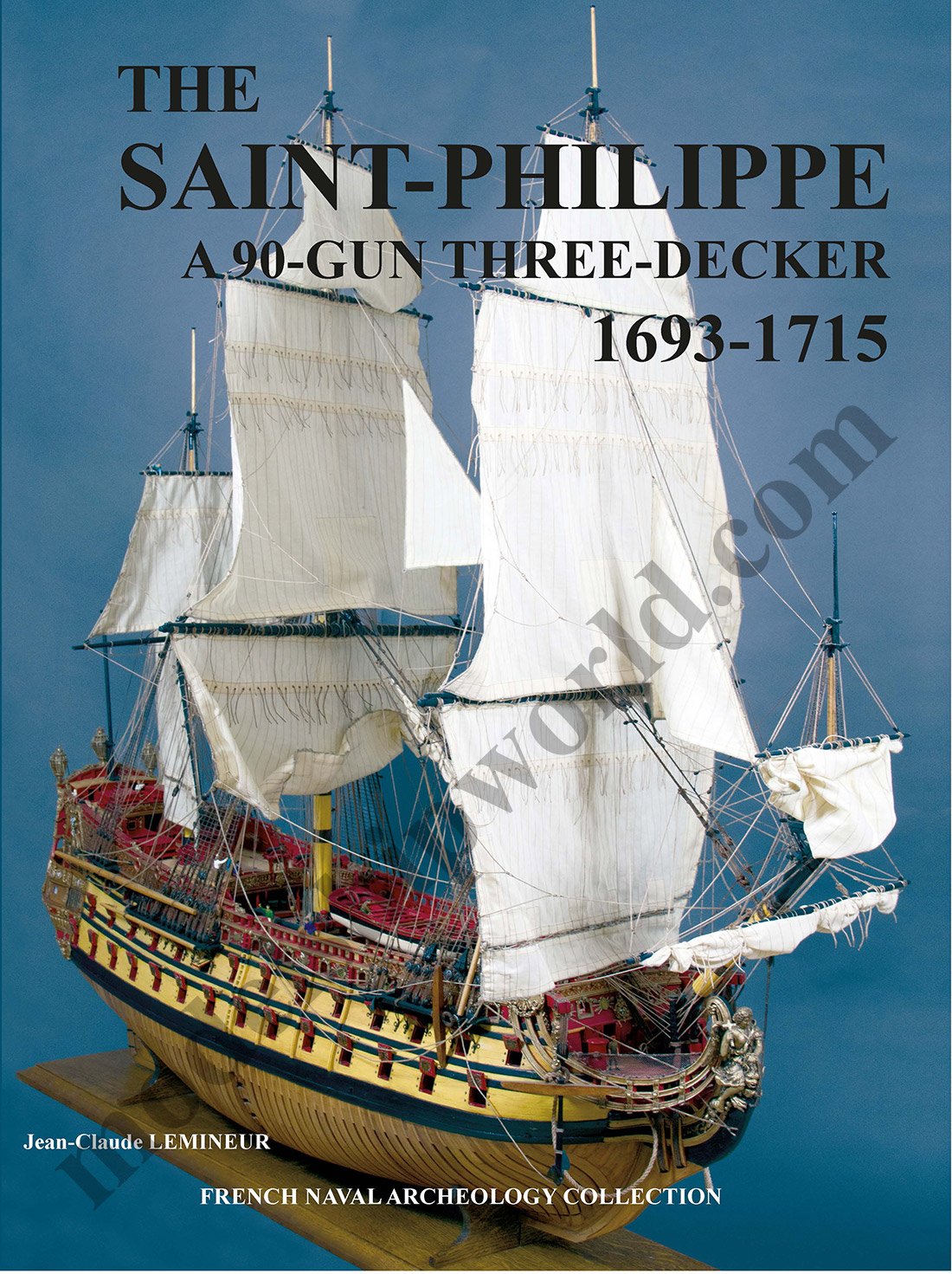
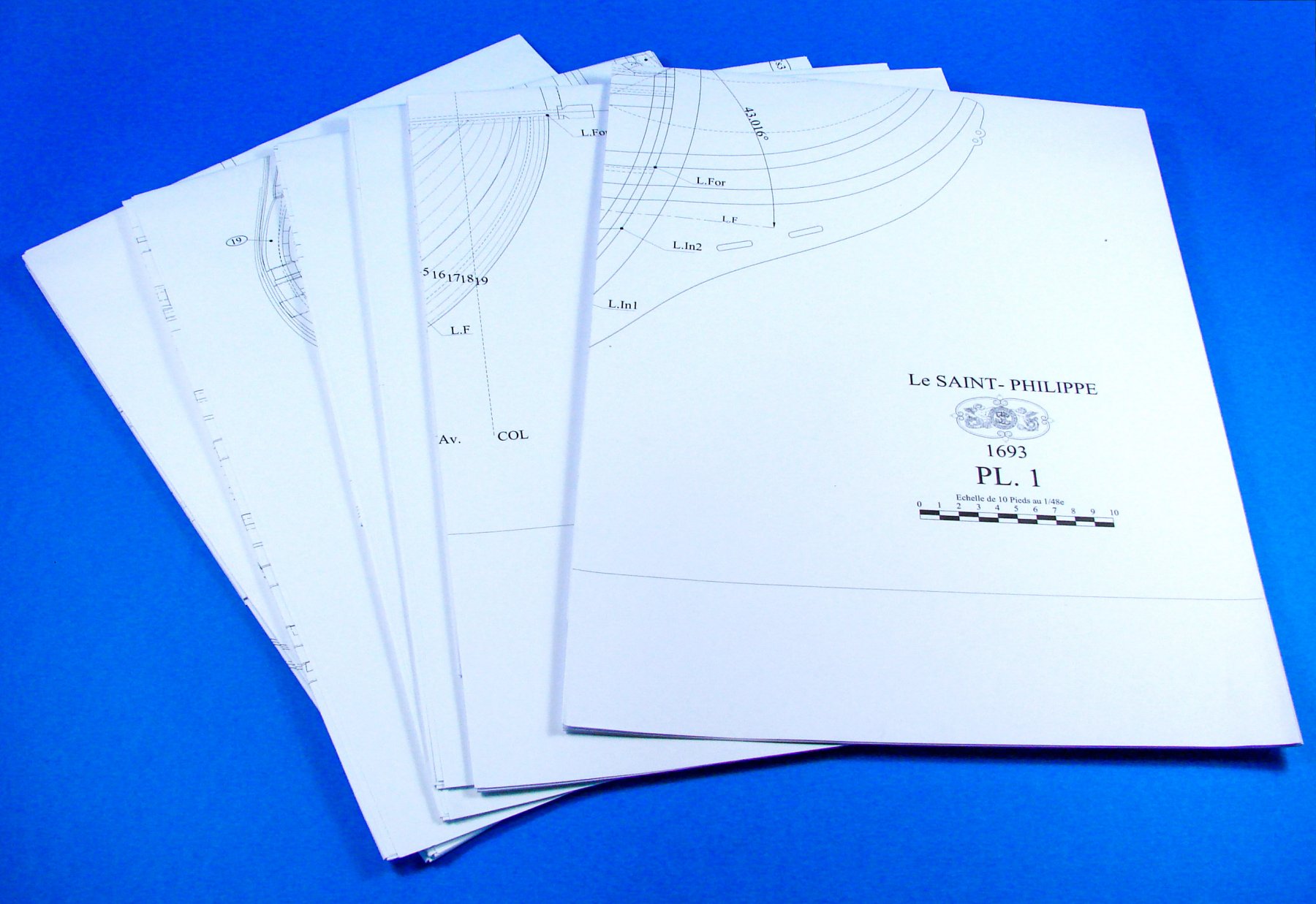
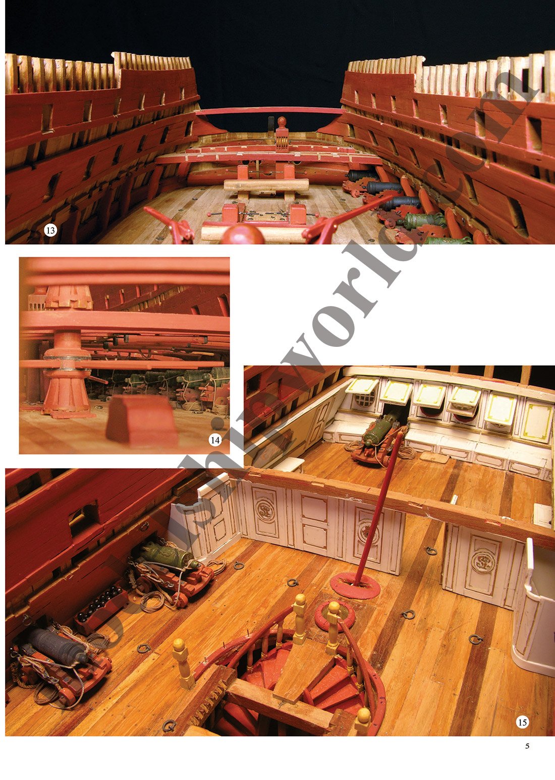
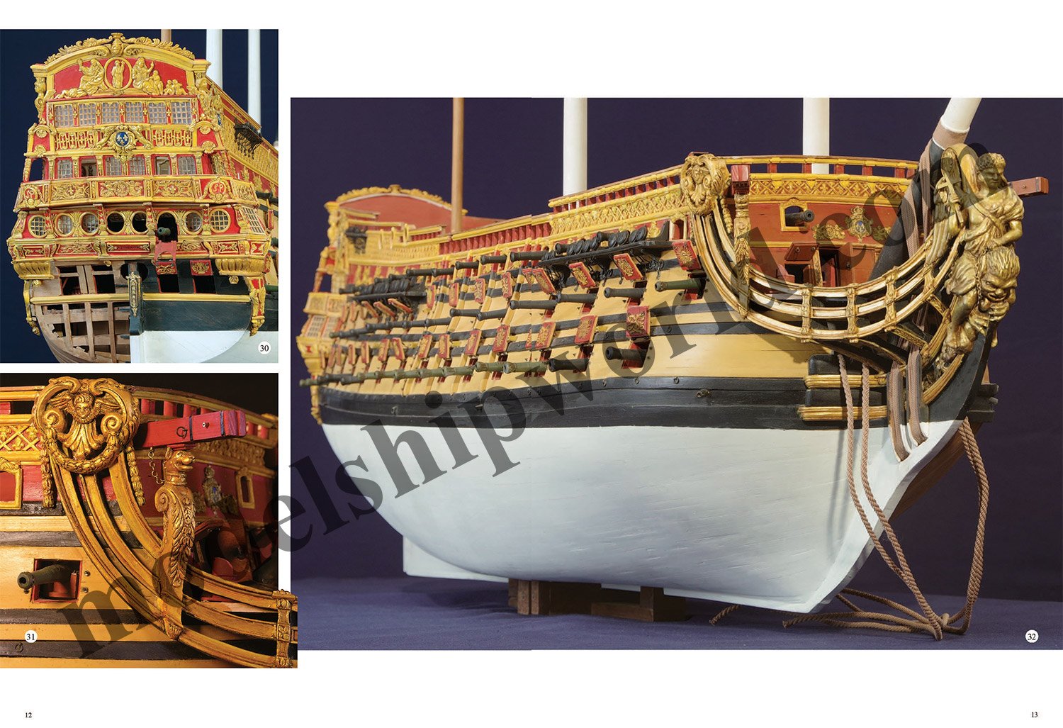
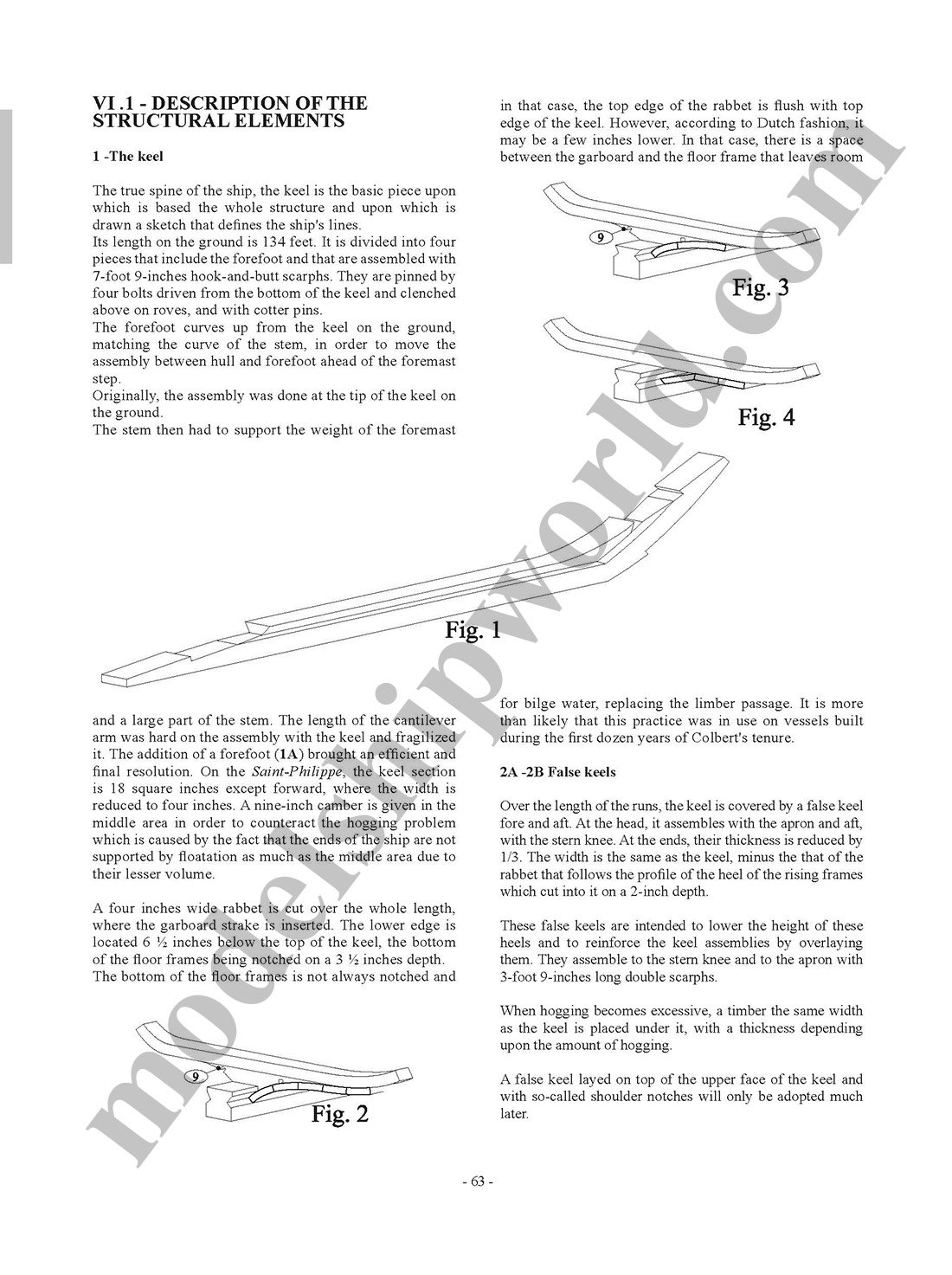
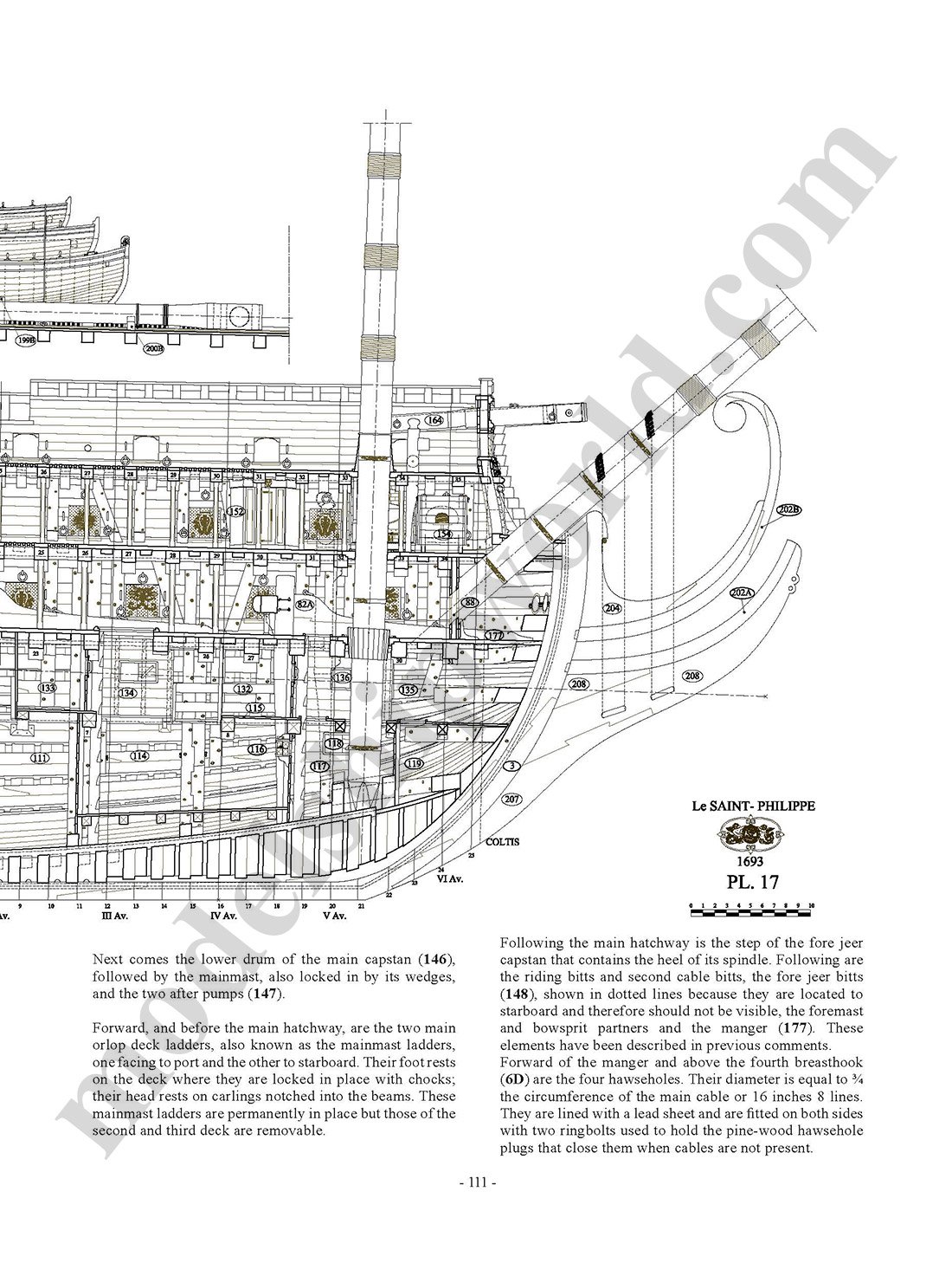
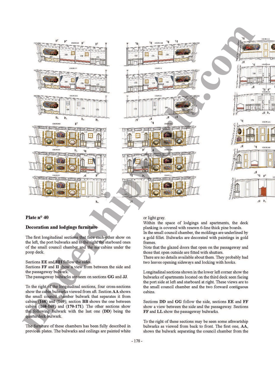
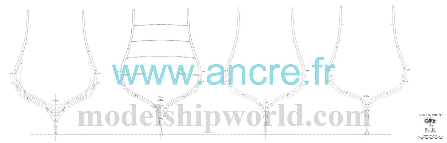
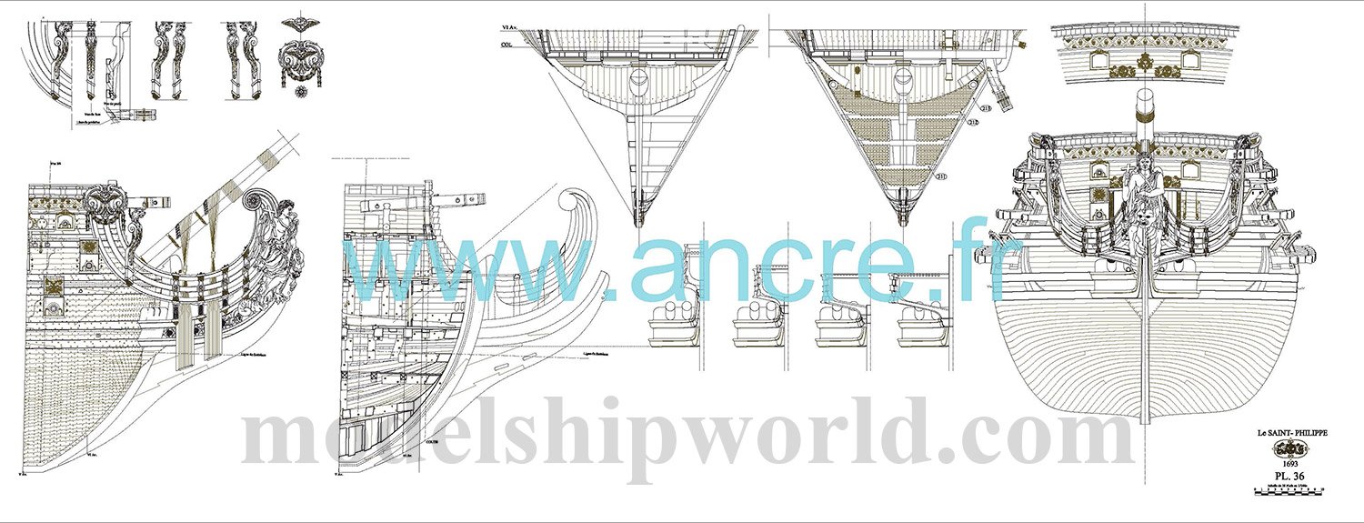
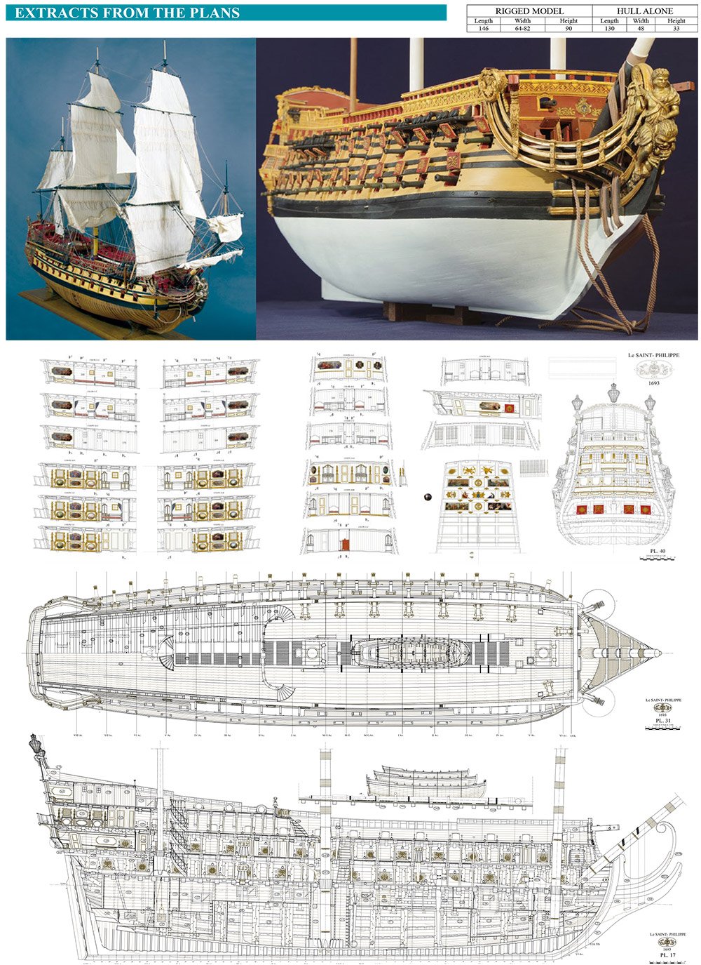
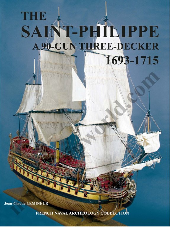
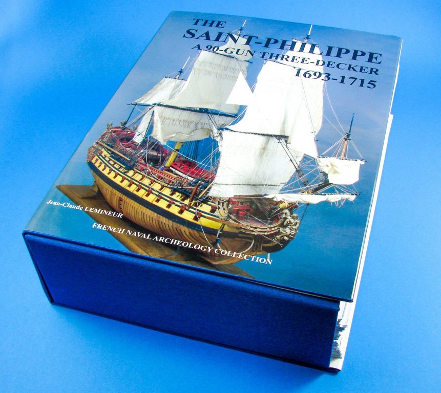
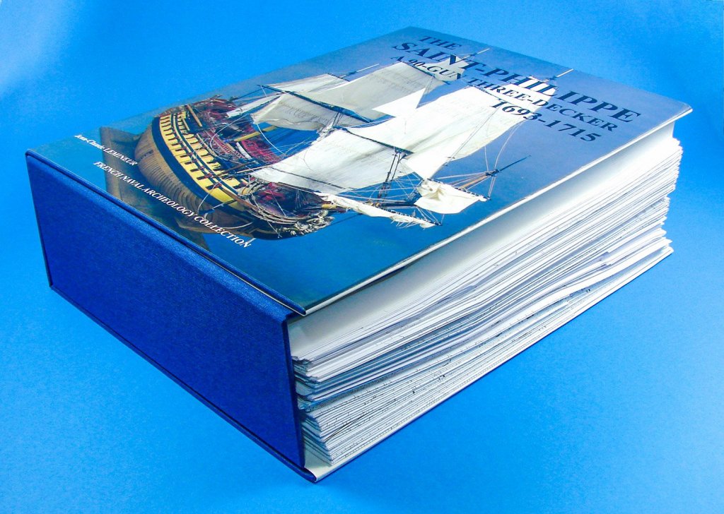
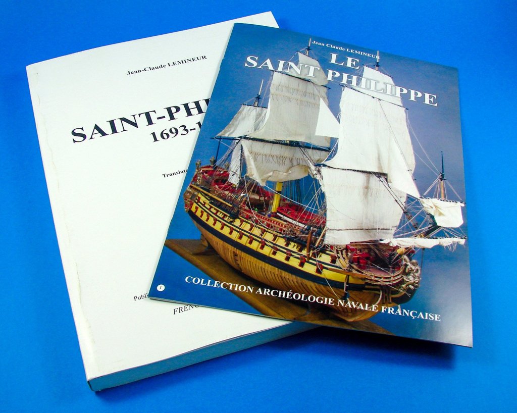
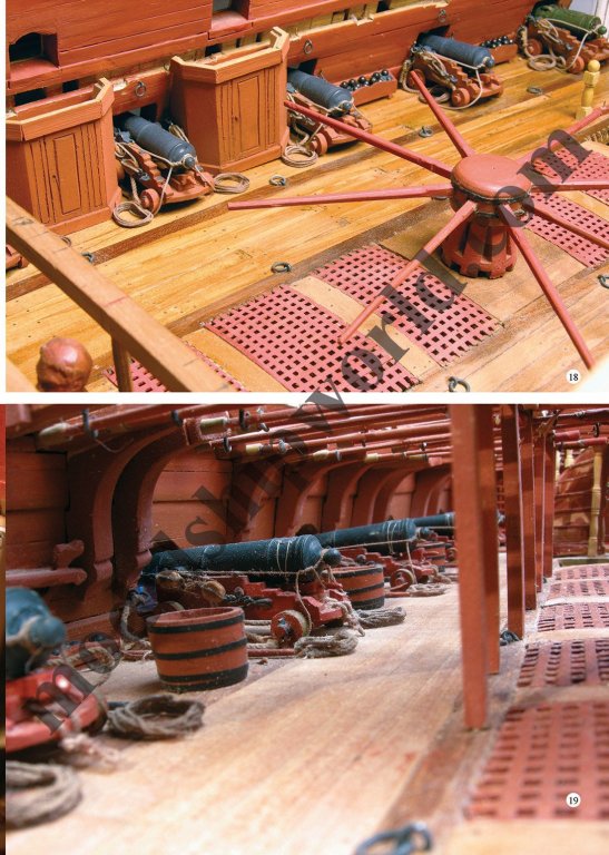
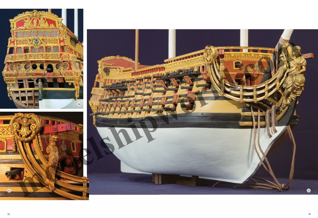
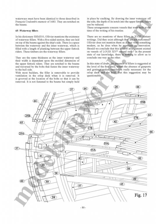
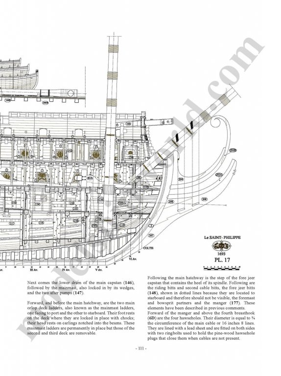
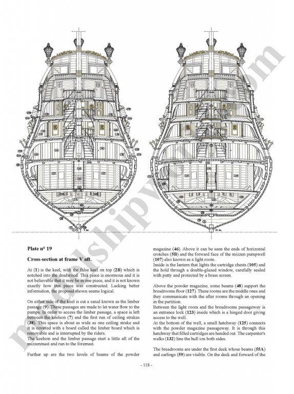
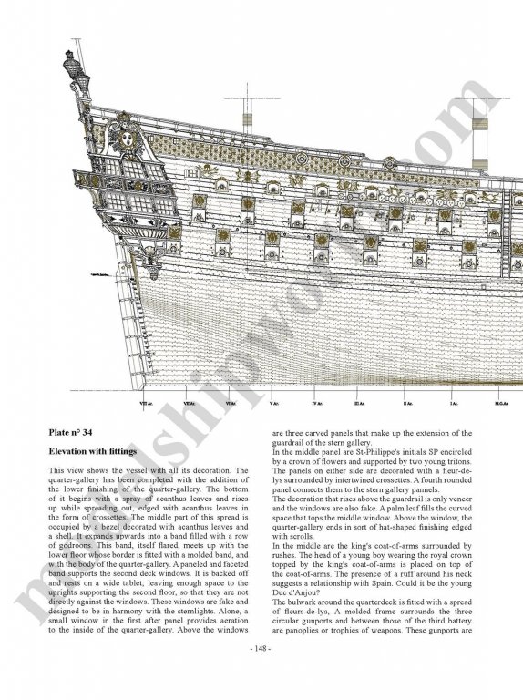
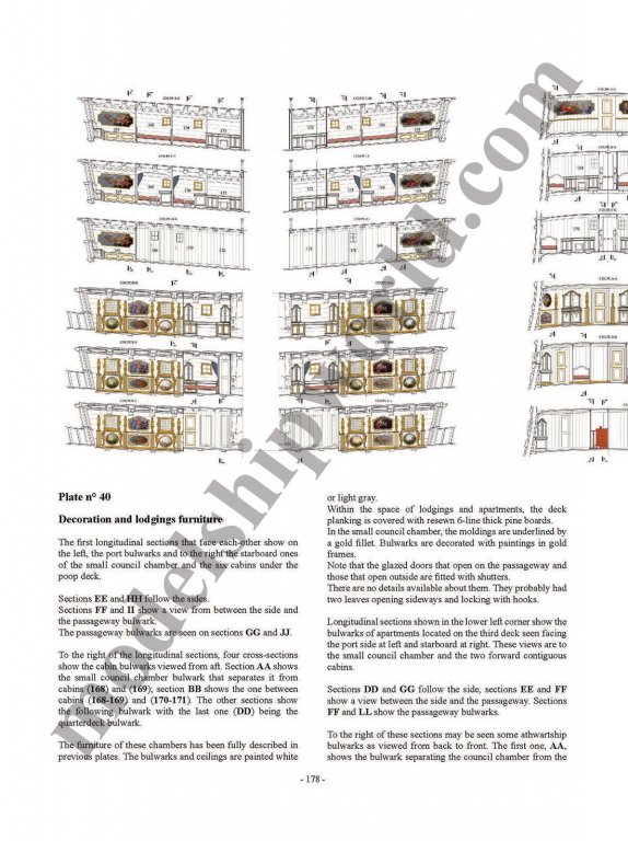
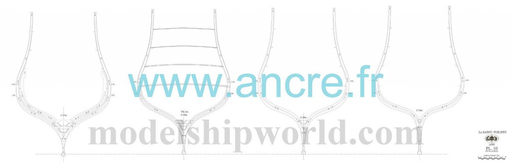
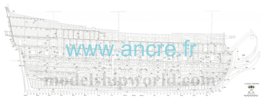
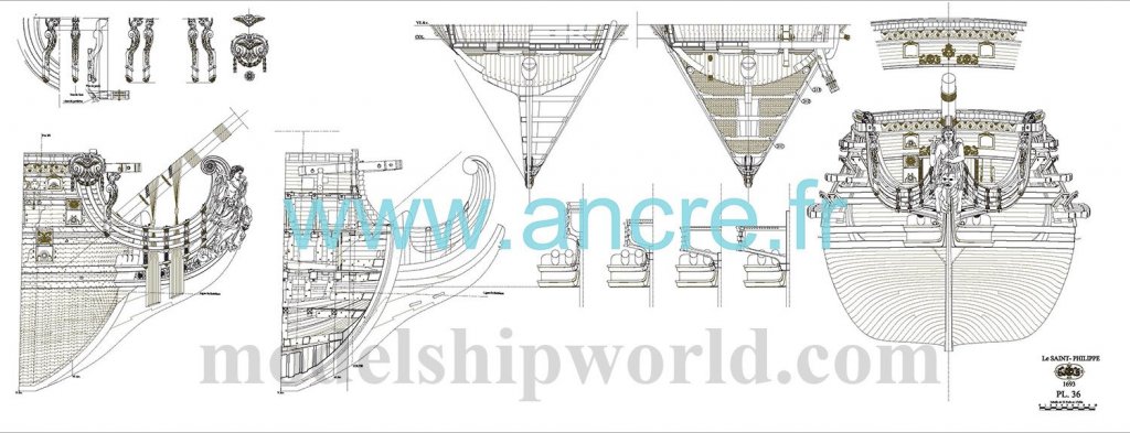
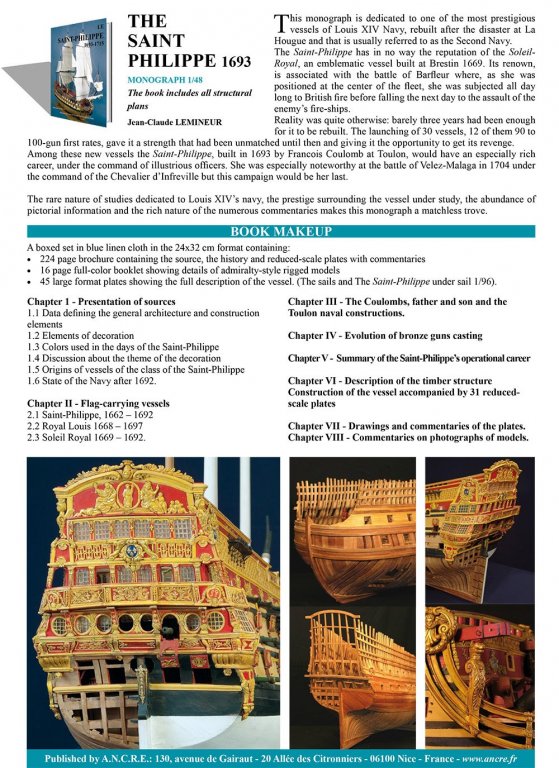
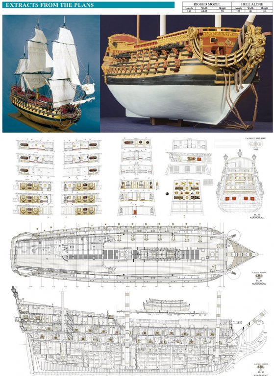
Monograph - The Saint-Philippe -1693 Jean-Claude LEMINEUR Ancre Catalogue # PHILA (for the English, 1:48 complete edition) Available from Ancre from €225,00 (scale drawing size dependent) The Saint Philippe was a First Rank ship of the line of the French Royal Navy, the second vessel in the two-ship Tonnant Class (her sister being the Tonnant). This ship was ordered in late 1692 to be built at Toulon Dockyard, and on 20 January 1693 she was allotted the name Saint Philippe, taking the name of a ship lost in the Action at La Hogue in June 1692. The designer and builder of both ships was François Coulomb, and they represented an enlargement of his design of 1691 for the Sceptre, with an extra pair of guns (and gun ports) added on each level. They were three-decker ships without forecastles. The Saint Philippe was launched on October 1693 and completed in December of the same year. She was initially armed with 90 guns, comprising twenty-eight 36-pounders on the lower deck, thirty 18-pounders on the middle deck, twenty-six 12-pounders on the upper deck, and six 6-pounders on the quarterdeck. The Saint Philippe was rebuilt at Toulon from February 1699 to 1700; she took part in the Battle of Vélez-Málaga on 24 August 1703. In July 1707 - during the siege of Toulon - she and her sister were undergoing a refit in the basin of Le Mourillon and avoided the scuttling order which affected most other French ships at Toulon; they were sailed to counter the British attack, and subsequently were used as floating batteries. The Saint Philippe was condemned at Toulon on 18 August 1714 and was subsequently taken to pieces. The Monograph The Saint-Philippe – 1693 is the very latest monograph from Ancre, having only been released a few months ago. I’ve seen numerous Monographs over the years, being lucky enough to thumb through them and be astounded at the levels of detail within. For me, this is the very first time that I’ve actually owned one, with this being sent by Ancre for review here on Model Ship World. Be in no doubt, this Monograph is heavy. The website itself tells you that it weighs around 4.5kg (almost 10lbs, for our imperial users), and it arrived by courier in a superbly packed and padded box, along with the other titles. Saint-Philippe itself is also has a clear film wrap that needs to be removed before we can explore further. Written by Jean-Claude Lemineur and translated by François Fougerat, this set is presented in a large presentation semi-slip case that opens out totally to reveal the contents within. The slip itself is jacketed like a conventional book, with a beautiful photograph of José Tuset’s completed model on the cover. General statistics for this Monograph are: BOOK MAKEUP 220-page brochure containing the source, the history and reduced-scale plates with commentaries 16 page full-color booklet showing details of admiralty-style rigged models 45 large format plates showing the full description of the vessel. (The sails and The Saint-Philippe under sail 1/96) Chapter 1 - Presentation of sources 1.1 Data defining the general architecture and construction elements 1.2 Elements of decoration 1.3 Colors used in the days of the Saint-Philippe 1.4 Discussion about the theme of the decoration 1.5 Origins of vessels of the class of the Saint-Philippe 1.6 State of the Navy after 1692. Chapter II - Flag-carrying vessels 2.1 Saint-Philippe, 1662 – 1692 2.2 Royal Louis 1668 – 1697 2.3 Soleil Royal 1669 – 1692. Chapter III- The Coulombs, father and son and the Toulon naval constructions. Chapter IV- Evolution of bronze guns casting. Chapter V- Summary of the Saint-Philippe’s operational career. Chapter VI- Description of the timber structure. Construction of the vessel accompanied by 31 reduced scale plates. Chapter VII- Drawings and commentaries of the plates. Chapter VIII- Commentaries on photographs of models. 1/72 dimensions Hull L: 86cm, W: 24cm, H: 32cm Fully Rigged L: 105cm, W: 42cm, H: 90cm 1/48 dimensions Hull L: 129cm, W: 36cm, H: 48cm Fully Rigged L: 158cm, W: 63cm, W: 135cm 1/36 dimensions Hull L: 171cm, W: 48cm, H: 63cm Fully Rigged L: 210cm, W: 84cm, H: 180cm 45 plates Pl.1 Schematic elevation of the vessel Pl.2 Schematic plan Pl.3 Body plan Pl.4 Construction of the head Pl.5 Construction of the stern-frame Pl.6 to Pl.14 Profile of the frames. Pl.15 Elevation of the timber framing Pl.16 Longitudinal section without furniture Pl.17 Longitudinal section including furniture Pl.18 Cross-section of the stern at station frame VI aft Pl.19 Cross-sections at station frames V aft to III aft Pl.20 Cross-sections at frames II aft to the main middle mould Pl.21 Cross-sections from the main middle mould to frame II forward Pl.22 Cross-sections from frame III to V forward Pl.23 Plan of the hold Pl.24 Arrangements in the hold and orlop deck Pl.25 Plan of the first deck timber structure Pl.26 Plan of the first deck including furniture Pl.27 Plan of the second deck timber structure Pl.28 Plan of the second deck including furniture Pl.29 Plan of the third deck timber structure Pl.30 Plan of the third deck including furniture Pl.31 Plan of the quarterdeck timber structure Pl.32 Plan of the quarterdeck accommodations and poop deck timber structure Pl.33 Elevation view of the planked hull Pl.34 Elevation view of the decorated hull Pl.35 Structure of the stern and quarter-galleries Pl.36 Decoration of the stern and head Pl.37 Furniture I - Anchors - artillery - galley Pl.38 Furniture II - Rudder - capstan - bitts Pl.39 Furniture III - hatches - longboat - boats Pl.40 Decoration and furnishings of the accommodations Pl.41 Mainmast spars Pl.42 Foremast spars Pl.43 Mizzenmast and bowsprit spars Pl.44 Sails (1/96 scale) Pl.45 The St-Philippe under sail (1/96 scale) Translated by François Fougerat Model under sail by José Tuset Michel Magerotte's single shell model Book Images Plate Images (very small sample) Images from colour brochure, of completed model Conclusion I’m still getting to grips with actually owning something as beautifully presented and comprehensive as this publication for the Saint-Philippe. It really is a masterpiece in its own right, and you’ll need some considerable shelf space to store it. The book is a beautifully printed perfect-boundpublication with high quality finish paper. As Ancre themselves say, “The rare nature of studies dedicated to Louis XIV’s navy, the prestige surrounding the vessel under study, the abundance of pictorial information and the rich nature of the numerous commentaries makes this monograph a matchless trove”,and that really can’t be doubted whatsoever. This is an epic release, and if you like the large, triple gun deck ships, then this should have a place on your shelf, even if it’s only to pour over the sheer wealth of detail that has been put together by its author. Working with the plans will be a delight as the drawings are all fine line, ensuring the correct size of parts when you measure up against them. They are also all very neatly folded, with no unnecessary creases. Having the colour booklet with a completed model will also not just give inspiration but gives you a rough idea of what you need to be aiming for, as well as such gorgeous details such as the interior curved staircases and their unusual format/layout. The book not only grounds you in the history surrounding the vessel and its origins and protagonists, but also into the construction of what must’ve been a most impressive ship, even for those days of ornamentation. Amazing to think that you can actually build a complete, miniature ship from this set, down to every smallest detail. Now….I just need a house big enough to build this model! The Saint-Philippe – 1693 is available in English, French and Italian languages, and plans are available in 1:72, 1:48, and 1:36 scales. The plans may also be purchased separately without the book, in 1:72 and 1:36 scales. Check out the options on the Ancre website. My thanks to Didier Berti of Ancre, for sending this Monograph out for review here on Model Ship World. To purchase directly, click the link at the top of the article.


- 13 replies
-
- 18
-
-
- plans
- monografie
- (and 1 more)
-
Please can we keep any discussion strictly to the build log subject? I've had to cull numerous posts.
- 455 replies
-
- 1
-
-
- fair american
- model shipways
- (and 1 more)
-
What a great idea! Yes, I'll do that. There's plenty of pear veneer to it. I'm starting to prepare the frames now, so this is a good time. ☺️
- 30 replies
-
- 6
-
-
- master korabel
- avos
- (and 1 more)
-
Only a little update today as I've been playing around with the upper bow timbers and fairing them into the adjacent ones. In these pictures, most of the subsequent upper timbers are only plugged into position to gauge a few things as I progress, plus I was interested in seeing how things would look! I was a little worried that the bow timbers wouldn't sand evenly into each other, but I needn't have as all is perfectly ok. My thanks to Peta_V for his encouraging words too. A Dremel was used to profile/finish the interior bow area, and a medium grit sanding stick was employed on the exterior. next up is adding the notches to some of the frames and dry fitting them against the pear inner bulwark lining.

- 30 replies
-
- 16
-
-
- master korabel
- avos
- (and 1 more)
-
Those blocks look great with laser and CNC machining 😍
-
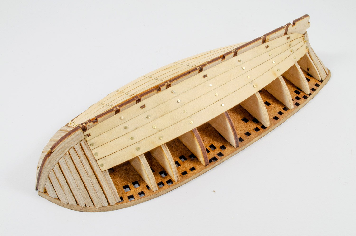
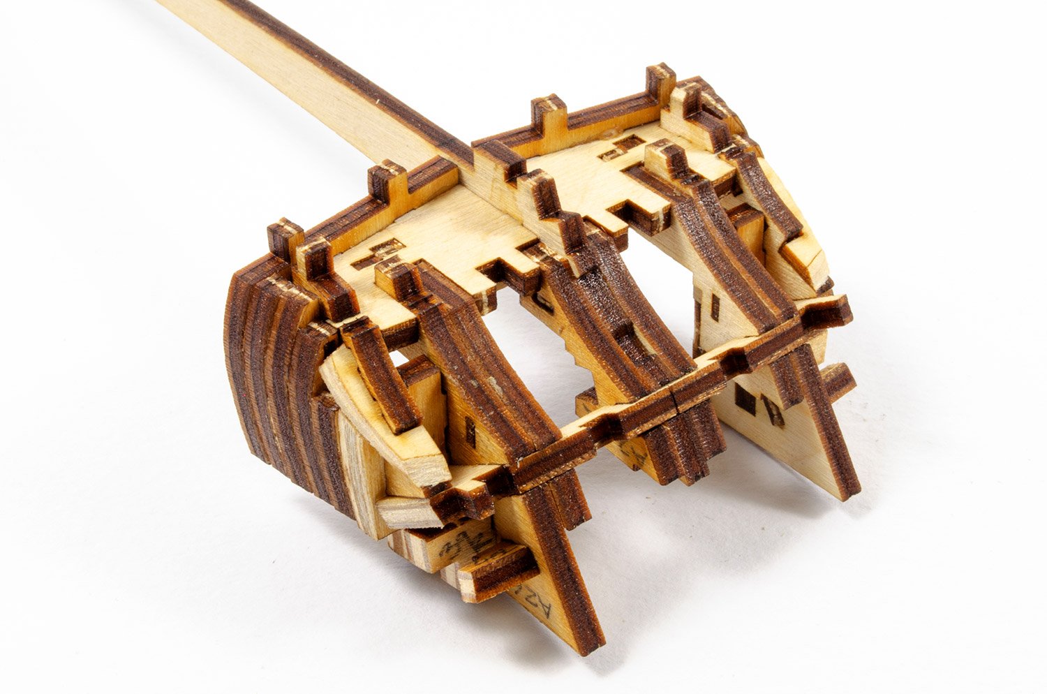
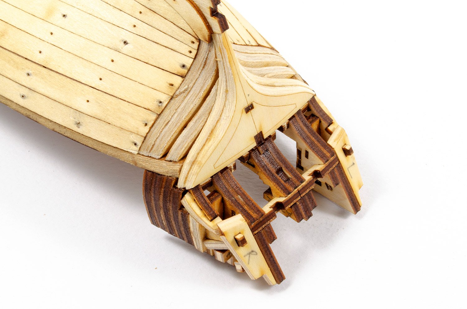
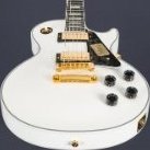
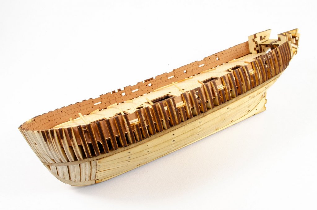
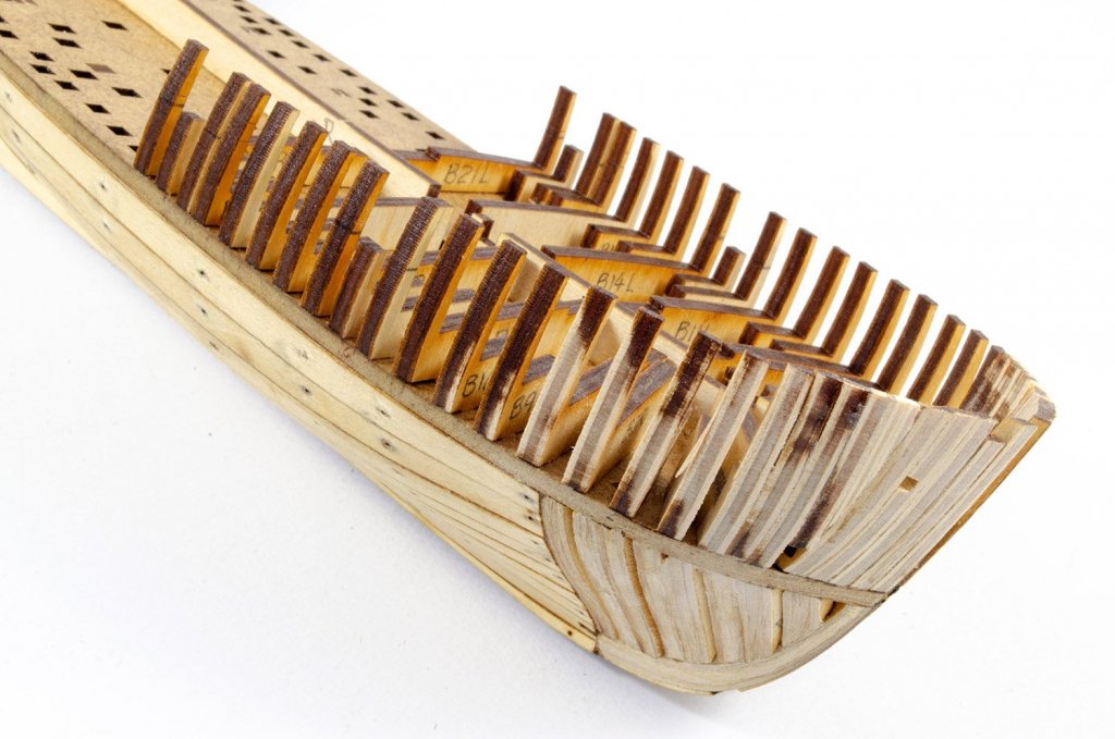
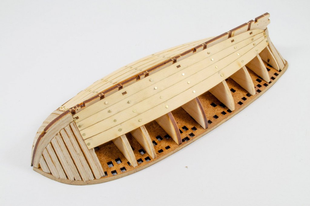
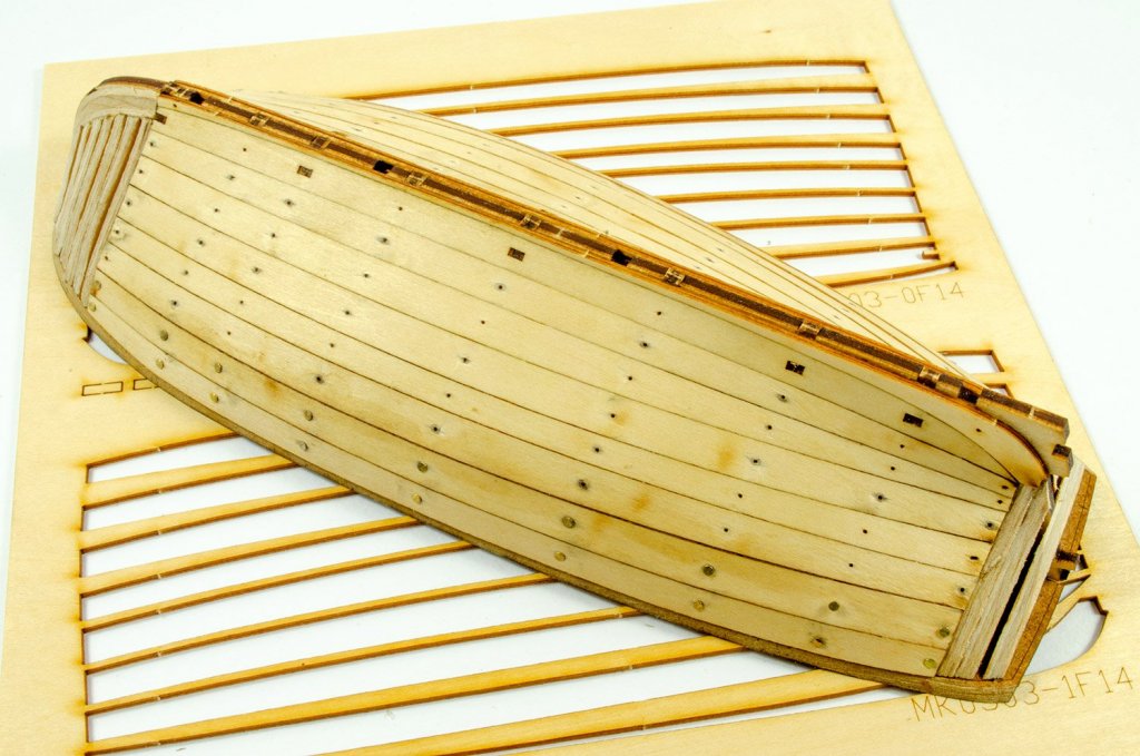
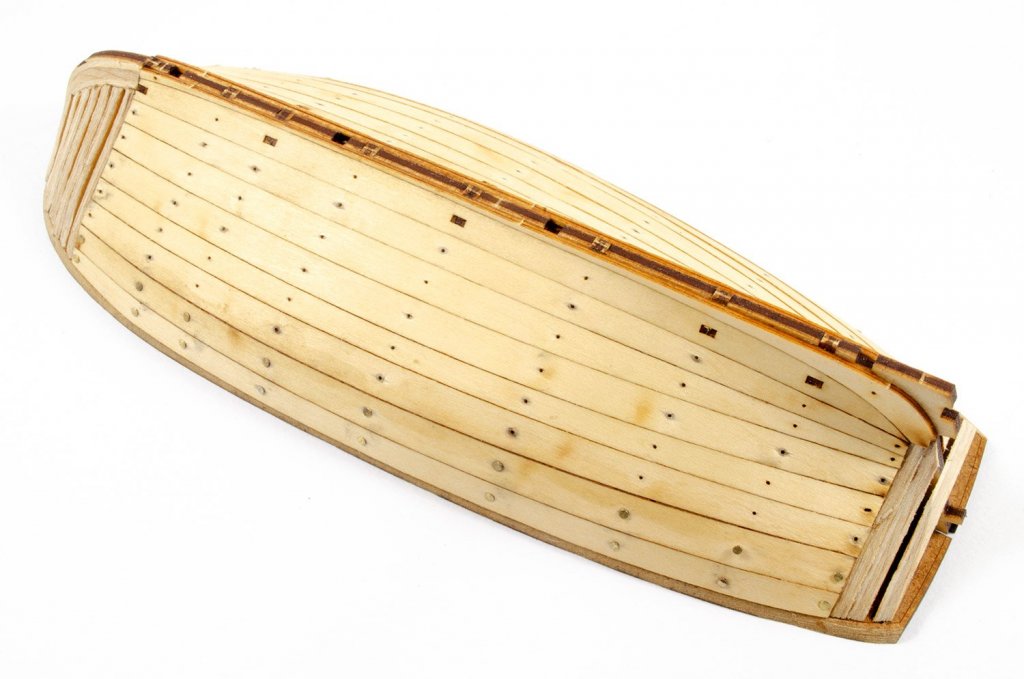
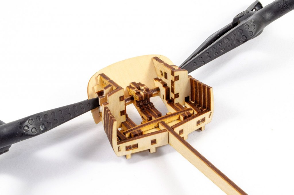
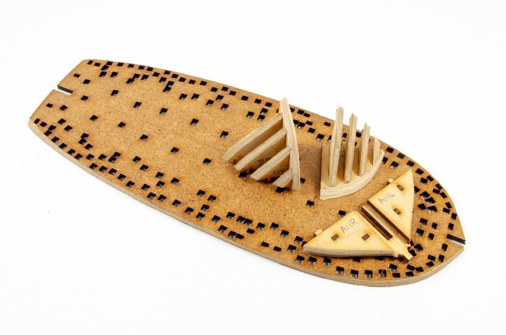
As well as laser-engraved bevelling lines, something else I've never used before are pre-shaped and cut planks. The first planking on this model fits like an absolute dream! Everything about this project is so far enjoyable. MK provided some beautiful little brass nails for this planks, and the holes for them are also laser cut. You couldn't ask for more. 😀 Remember also that I still need to give the hull a final shaping and sanding later in the build and everything here is just bevelled with a Dremel before any gluing. Next up is the stern quarters. This builds up a little like one of those Puzz-3D models, with lots of interlocking parts that fit perfectly together. a little bevelling is needed here and there, but very minimal. With the stern fitted, the rearmost bulkheads were fitted, carefully bending them to the bevelled curve of the MDF main section. The transom area is one that takes a little more effort with, and definitely some care. After bevelling, the ply transom core needs to be soaked in water before you can do this. Thankfully, the ply is quite pliable and 5 minutes in very warm water was all that was needed. The counter transom also needs bevelling and bending. Here you can see the two put together and with the pear and black veneers added to the inside area. The pear is beautiful but VERY thin. I managed to break it, but you can't tell, thankfully 🤣 Tonight, I made up one of the bow sections. These are built from 5 pinned parts that have some bevelling marks. Because the laser engraving machine can't engrave the underside the sheet of parts, you will need to add some bevelling marks yourself by first dry-fitting the parts and marking with a pencil. Remember, the bevel is on the inside and outside of this section, hence the extra marks you need to make. When done, the parts are pretty level and will only need a few swipes with sandpaper. More soon!!


- 30 replies
-
- 15
-
-
- master korabel
- avos
- (and 1 more)
-
I've spent time pouring over the actual Caldercraft kit a few years ago. A modeller friend of mine lent me his for a couple of months, and the only reason I didn't buy was because I was looking at a house move at the time. I'm fairly well versed on the construction. I'm also in receipt of a mind-blowing quantity of photos, plans, drawings, instructions for the forthcoming Amati. In my humble opinion, there isn't a comparison. This one blows it away in terms of detail, and the information I have on accuracy. Knowing what is now coming, and the sheer expense of something like this, don't sell yourself short.
-
....hold in there!!!
-
You're a machine. That's looking real impressive.
-
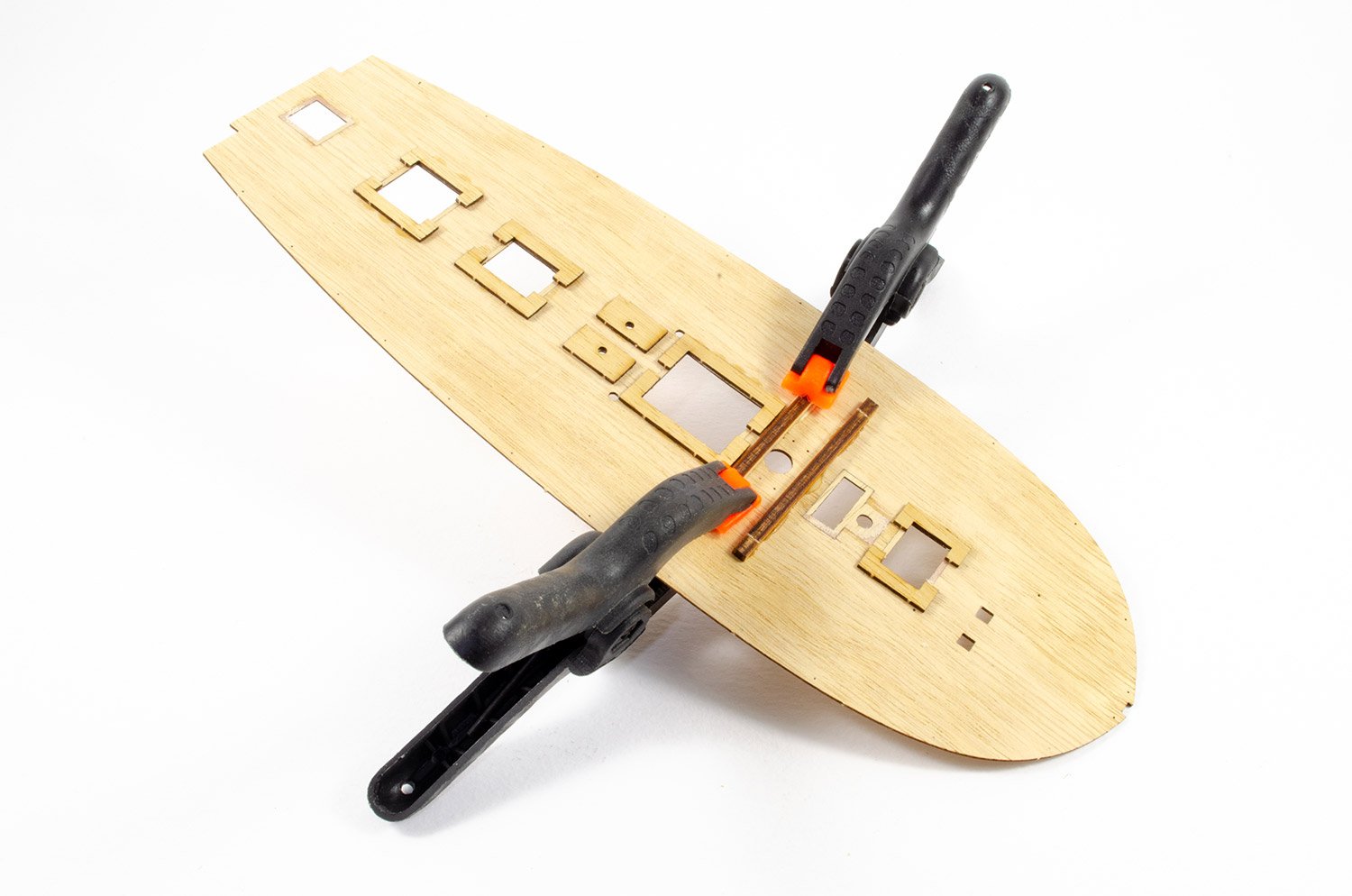
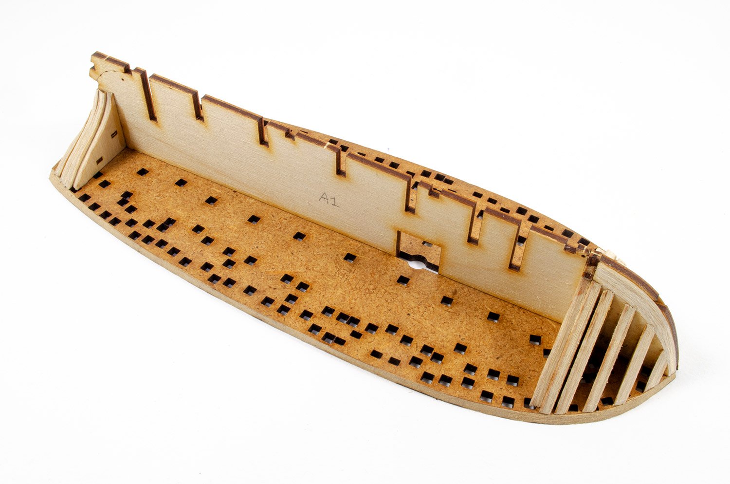
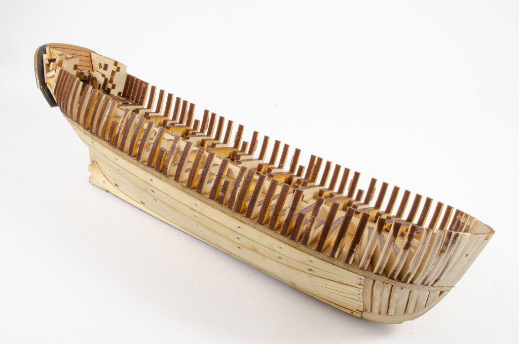
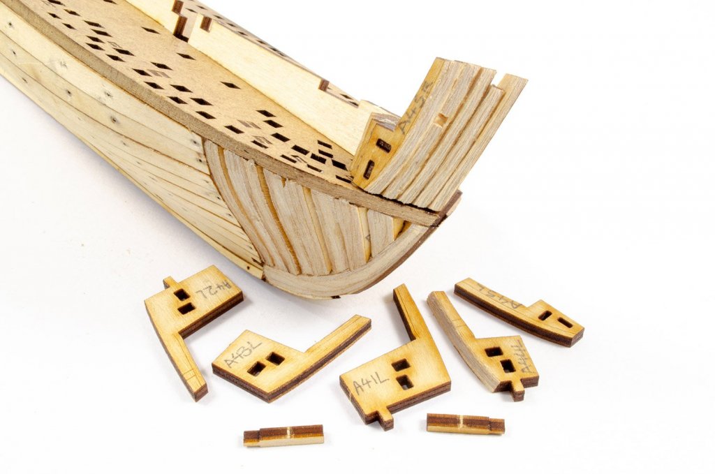
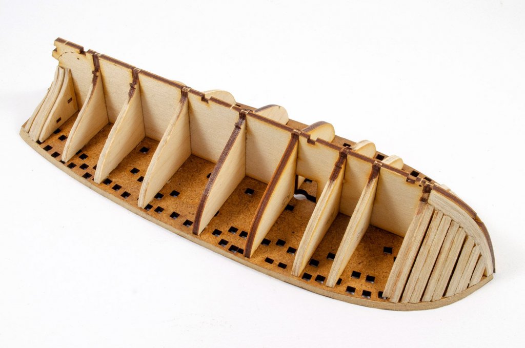
I will do. It's great to be back at a bench again and doing something I enjoy! My room is already a dust bucket, and I've only been back at it for a few hours! Ok, before I make a start with removing any parts from the first two sheets of laser cut elements, I decided to use the instructions as reference and number them all. The kit itself is pretty intuitive when it comes to part placement, but never underestimate the power of stupid. This was a little insurance policy for me. Now, I've not used my Dremel for years. I had to go to the attic and actually find it. After removing the parts for the bow cheeks, the first job was to profile/bevel them against the laser etched lines. I know those lines are hardly a new innovation, but this is the first kit I've actually used them in anger. Bevelling the ply is a pretty easy job, and I just went at my own pace at 8000RPM. I also bevelled the large main part into which everything plugs. Rear former parts are aligned with a series of laser-cut pins. Note the different orientation of them, so you can't get the parts mixed up. The rear formers are now glued to the false keel using Titebond Ultra, and the false keel glued to the main plan part. I now glue the bow cheek sections in. These all fit precisely with absolutely no gaps and no need to fudge anything. Very impressive. The rest of the formers are now bevelled. There's no work to do on #15 and #16, so those are glued in place first. Again, all parts have tabs which means they will only fit one way around, keeping the clumsy at bay. You'll see that some of these also have plugs that will lock into the garboard plank. The last thing to do before planking is to glue the bulkheads into place, making sure that any excess glue is removed from the other sockets on the main plan part. With these fitted, the infill parts are also added between the bow cheeks. Next stop.....planking!

- 30 replies
-
- 20
-
-
- master korabel
- avos
- (and 1 more)
-
Great to see this one come together so quickly. It must only have been a few hours since you said you were starting this 🤣
-
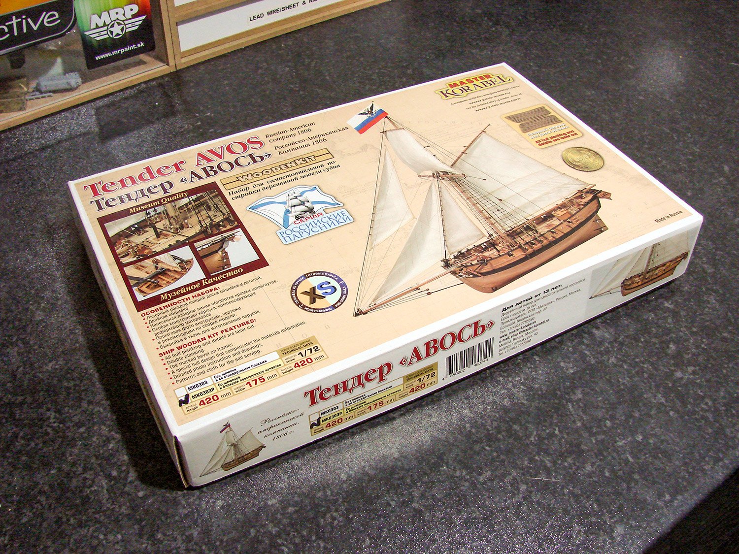
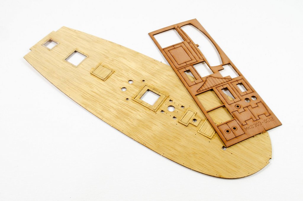
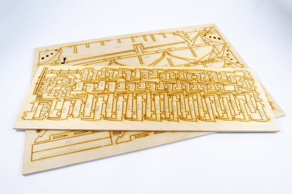
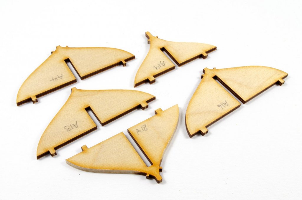
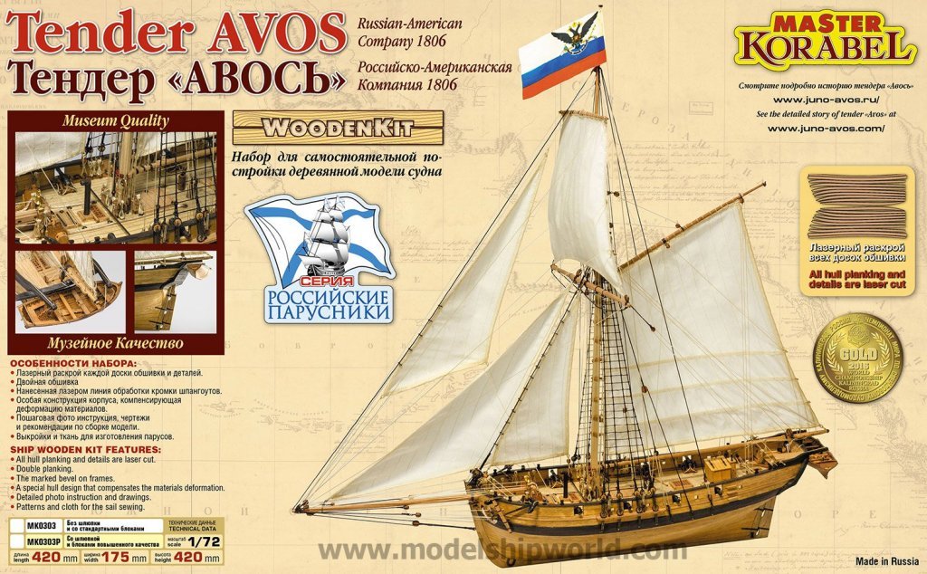
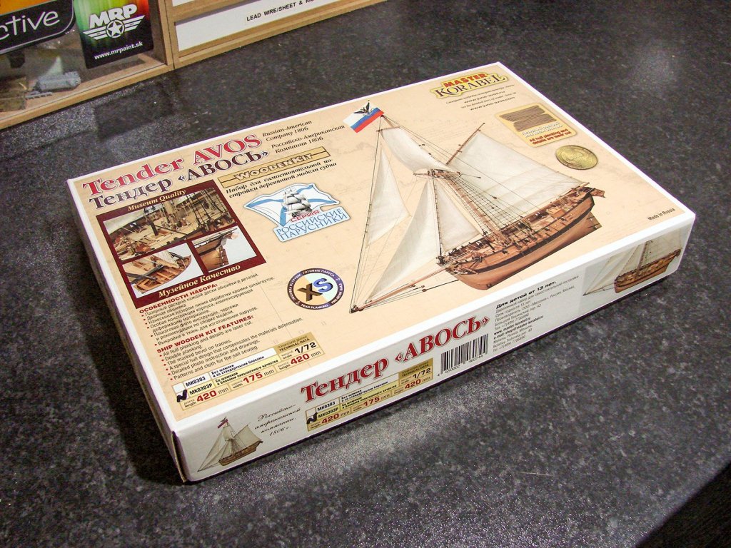
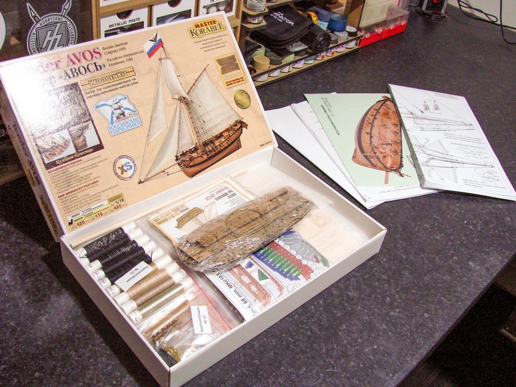
Hi crew, I've had to be a little mercurial when it comes to how I'll spend the next months before I build a test (another!) of Amati's forthcoming 1:64 H.M.S. Victory so I can do the photos for the construction manual, so I was originally going to bash away at my Panart deck section. I was then going to plank the Caldercraft 1:80 Mary Rose I've had for around 15years. In the end, I decided the best way to spend that time was on Master Korabel's diminutive but gorgeous 1:72 Tender Avos, reviewed HERE and soon to be available from Vanguard Models in the UK. I've been watching this beautiful build of this model by Peta_V, on Model Ship World, and the kit I have is the same XS/Exclusive version. My plan is to do as much work as I can until Amati's parts land, sometime in October. Master Korabel's kit really is gorgeous, superbly presented and manufactured, and has some innovative design features that are there to make things as trouble-free as possible. The box is fairly small, but it pretty heavy. Planking is also laser-cut and etched with plank and nail detail. Everything starts with the flat deck-shaped component into which all the other elements plug. Work starts on Saturday, and until then, I'll be studying the plans and watching Peta_V's build even more!
- 30 replies
-
- 13
-
-
- master korabel
- avos
- (and 1 more)
-
...and that is happening, from Amati.
-
Thanks for that. I'll check it out 🤗