HOLIDAY DONATION DRIVE - SUPPORT MSW - DO YOUR PART TO KEEP THIS GREAT FORUM GOING! (Only 13 donations so far - C'mon guys!)
×


robnbill
-
Posts
841 -
Joined
-
Last visited
Content Type
Profiles
Forums
Gallery
Events
Everything posted by robnbill
-
Over time the tool becomes coated with the CA. Whe. This happens cut the end off and form a new ring. You can keep doing this until it becomes too short then replace the wire with a new one.
-
To handle the CA take a brass wire and insert it into a dowel. Then form a small ring in the end of it. Put a drop of CA on a piece of parchment paper or some other surface it will not soak in on. Then take your block wrap the line tightly around it and hold the two loose ends between your fingers. With the other hand dip the ring in the ca and touch it to the rigging on the side of the block. Use thin CA and it will immediately adhere to the line and block. The tool allows you to contro, the amount of CA you apply. This is what i found works for me.
-
 Today I finished adding all the coils to the rigging and started working the davits. I have debated back and forth over using the Mamoli supplied davits which are metal or make my own ones from wood. While I was cleaning up the metal ones fate and my clumsiness decided the issue. I dropped one of the metal davits and it shattered when it hit the floor. So I pulled out the AOS and am using a modified approach to the davits. I understand that during the Connie's career she had both curved and straight davits. The straight ones would need to be at quite and angle for the ships boats to hang clear of the sides and rigging so I am making davits with a slight curve. I will pin the bottom to either a wire bracket or a bracket I will solder up with brass sheets. I am already liking the davits more than I did the metal ones. I am adding the features to the davits based upon the AOS, so the same ship's cleats, foot ladders, etc. I will take photos tomorrow of the progress.
- 335 replies
-
- 3
-

-
- Constitution
- Mamoli
- (and 3 more)
-
I have found that if I place a tiny amount of CA in the groove it holds the thread in place. I either loop the thread around the block then apply the ca or I touch the CA to the groove then put the thread in it.
-
I believe this had to do with the history of what was most stressed as well as what was harder to replace. On some ships, such as the Balclutha (in the San Francisco Maritime Museum) the spare spars were left in their raw state and the carpenter would carve and shape them once they were needed. I also know that there are some pretty impressive pine trees growing wild now on the Big Island of Hawaii that supposedly were brought there by Whalers wanting to have ready access to the wood for spares when hey arrived from around the horn. However, what I was told was the climate in Hawaii caused the trees to grow so fast they were too soft to use.
- 93 replies
-
- 2
-
-
- ships boat
- model shipways
- (and 1 more)
-
YEAH! I completed the rigging yesterday morning. I received the new line from Chuck on the 24th and was able to continue to work on the ship's rigging. I did run short on the single blocks, I need 4 more so I used some walnut strips, and made them. Today I started working on the coils. I was able to complete the coils on the port side and those on the fife rails for the fore and main masts. I used a jig similar to that others have used on the side working the wraps between two nails. Then I touch each end with CA and slide them off the nails. I cut one end off on the back side and so the other end to loop around the other end and create the loop for hanging the coil off the belaying pin. It took a few tries but I managed to get a system down that created coils in the shape I liked them. Tomorrow I will continue to work on the coils. I also replaced three of the deadeyes for the main and mizzen. They had twisted and were not as neat as I liked. I planned on relaxing them so I spent a bit of time today and redid them. I did not take any new photos since the ship does not look much different than it did the last photos. Once I complete the coils, I will install the side davits. At that point, I will move the ship out of the shop so I can make the three remaining ships boats. I do not want to make any sawdust around the ship with the rigging in place. So when I move the ship, I will set it up with a light background and take some better photos. I also found a site called table legs.com that I plan on ordering the legs for the case from. I want to have fluted legs, I wheel I could build them, I would rather spend the time on the ships boats or working on the Eagle. So the end is in site! Woo Hoo!
- 335 replies
-
- 5
-
-
- Constitution
- Mamoli
- (and 3 more)
-
Reading/decoding Mamoli Rigging Charts
robnbill replied to robnbill's topic in Masting, rigging and sails
One other note: Sometimes they will have a part shown with Dx or Sx (or both) next to the number in the plan. Dx means Starboard side, the D = "Dritta or Starboard". Sx means Port side S= "Sinistra or Port". -
Fletch, I have attached a pdf of a scaled Brodie Stove drawing. I did this based upon the AOS and other documents related to the stove. You might want to use it since you will be building a stove for the gun deck. I have this in DeltaCad shut you want it in a CAD format. Just let me know if you do. Brodie Stove.pdf
-
She is coming along.
-
Thanks Joe and everyone for all the likes.
-
FYI, I decided to use my downtime from the rigging to document the process to decode the Mamoli plans. I posted it in the rigging section on this forum. It is located at http://modelshipworld.com/index.php/topic/9150-readingdecoding-mamoli-rigging-charts/. I thought others might find this a bit useful. I break down the process to figure out what they are asking to do in the rigging.
-
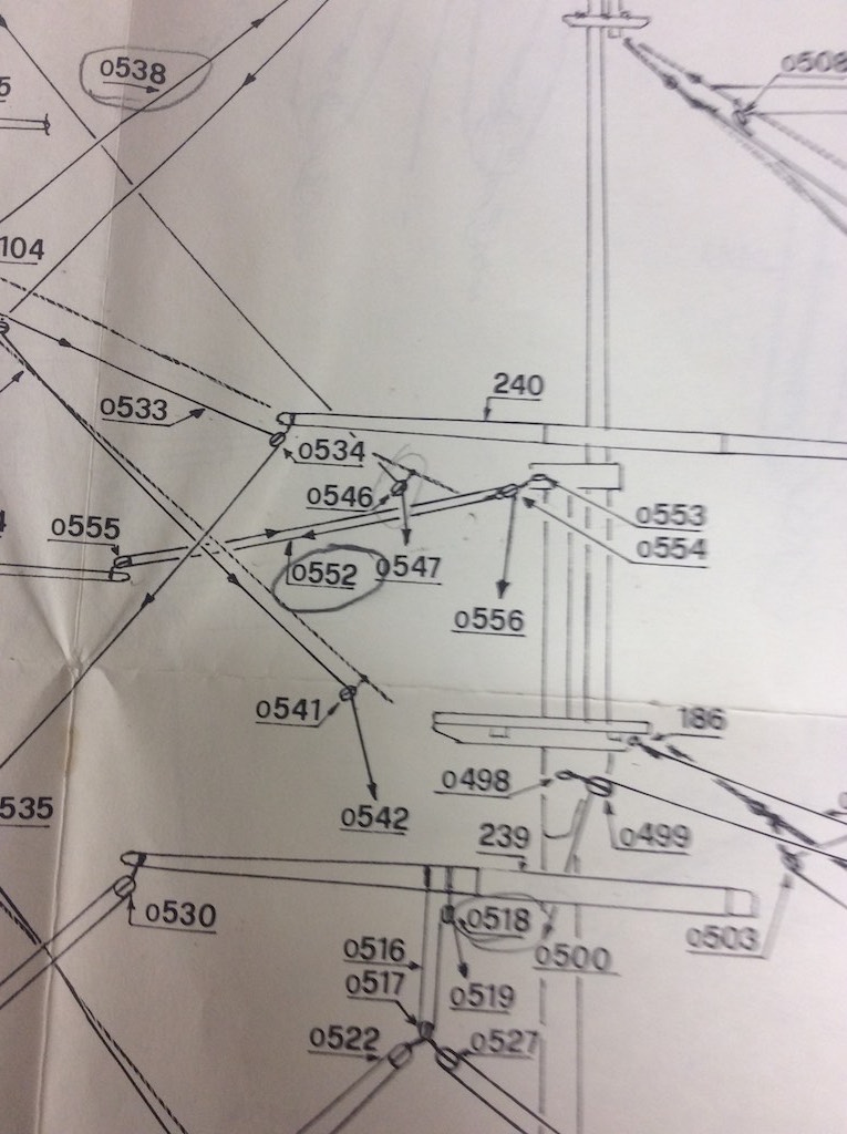
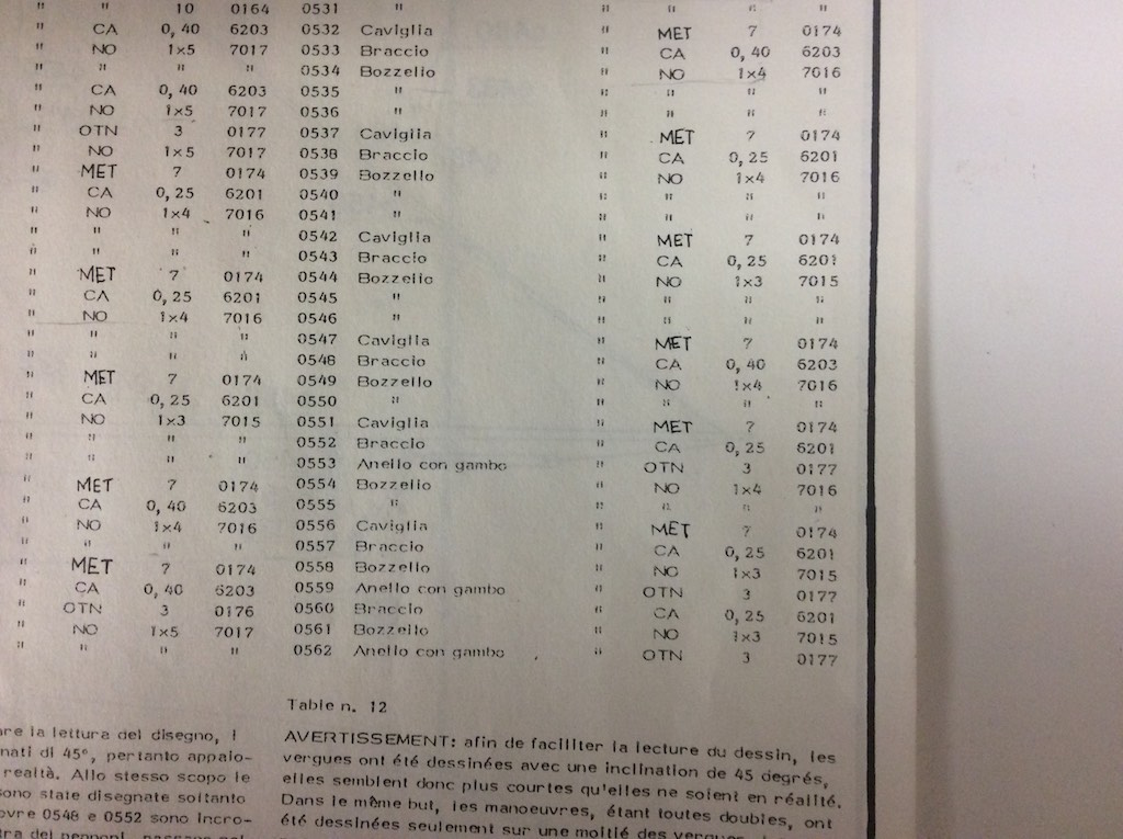
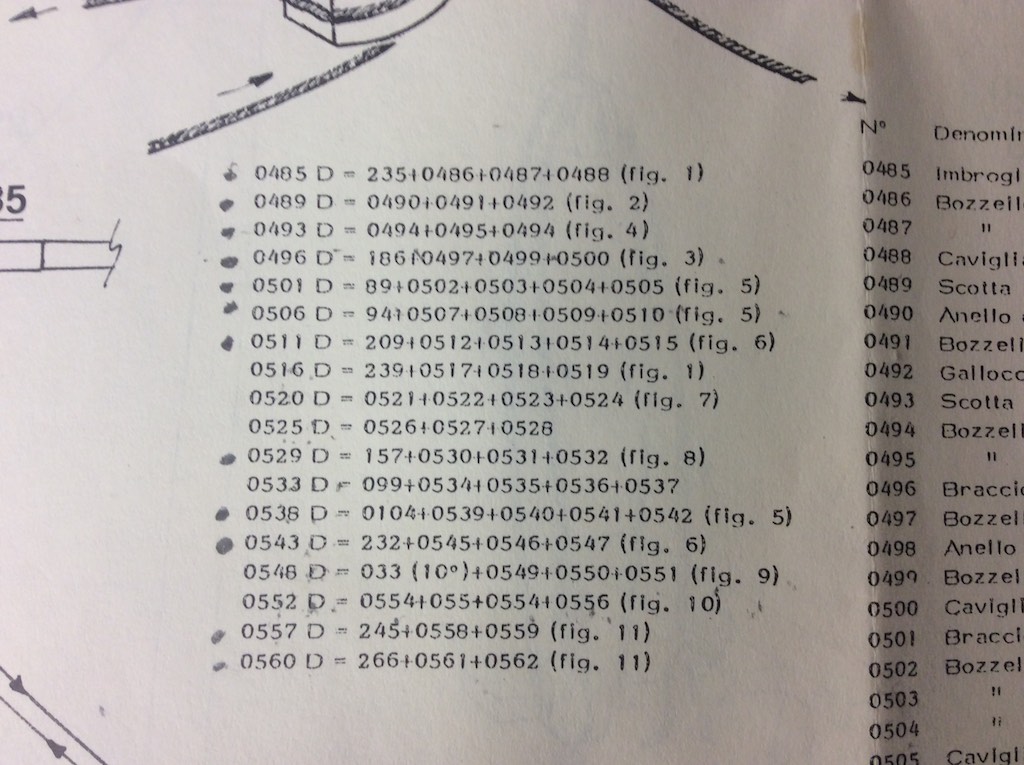
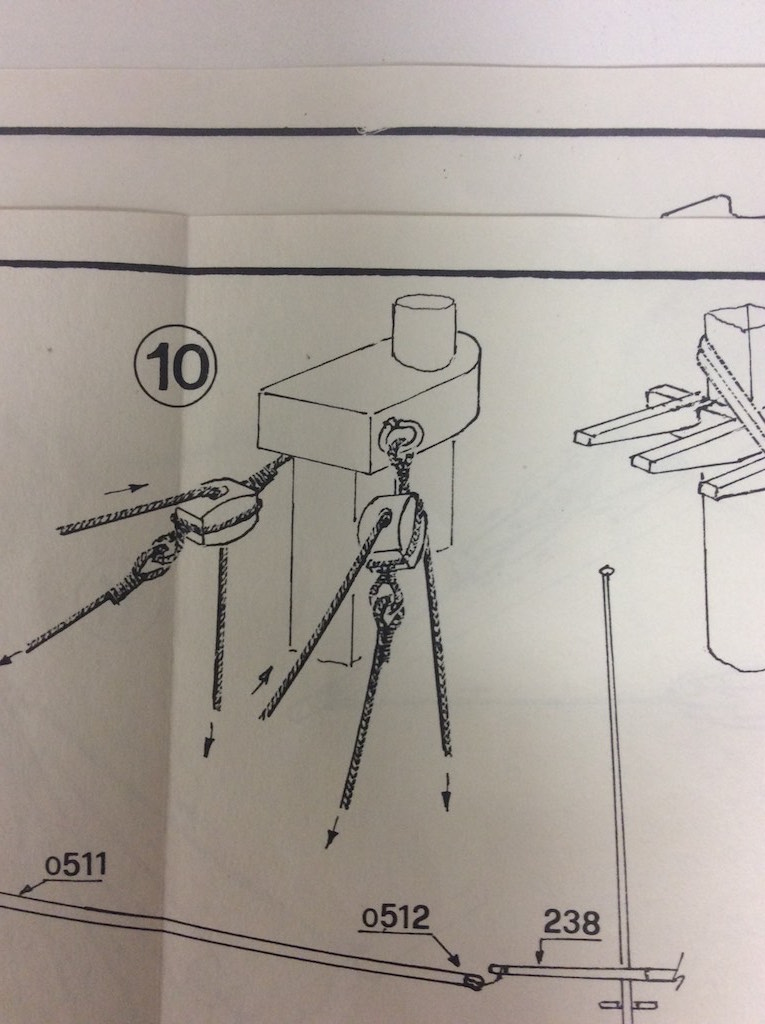
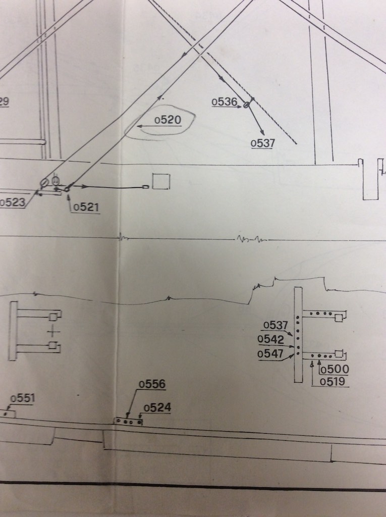
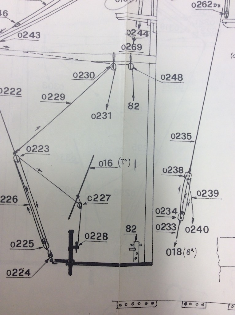
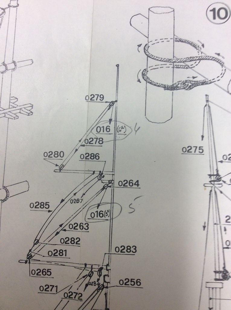
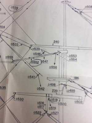
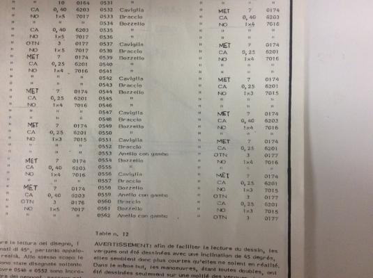
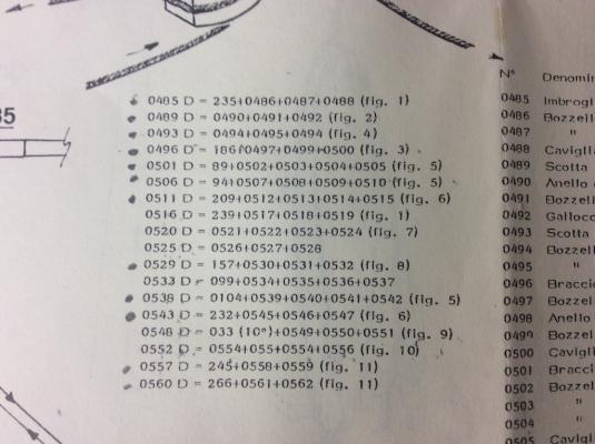
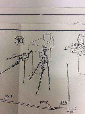
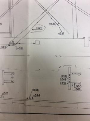
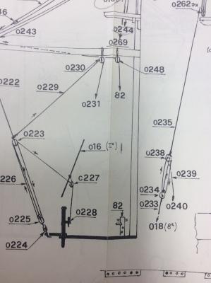
I spent quite a bit of time learning how to read the Mamoli rigging plans. Since there were no explicit instructions on how to interpret the drawings I spent a great deal of time looking through them before I figured out their method. Once I did, it was pretty straight forward. I thought perhaps others might find this useful. Perhaps this is how all rigging plans are done. Since the Connie is my first kit, I have no reference. I also need to mention this kit was purchased in 1991 so it may have changed. However for what it is worth here is how my plans are interpretted. There are two tables on each rigging page. The first table is on the right and lists all the parts, this is standard on all the Mamoli pages. However the second table, placed directly to the left of the first left is only on the rigging pages. the tables are not really labeled or numbered but they are consistent on how they arrange them. The only difference is where they are placed on the plan. For this illustration I will show how to interpret the rigging on the Mizzen (part o552) circled on the drawing. Here is a copy of the appropriate section from the plans: This shows a rigging set running from the tip of one of the Mizzen booms to the cap just above the Main Mast's fighting top. First we need to see what the parts are for this rigging. The size of the line, the size of the blocks, etc. For this we turn to the right most table on the plans. This table is on all of the plans an lists the all the parts of the ship as well as the various sizes. In some cases, the part number might refer to a different page of the plans if the part was installed much earlier so you might have to refer back to another page of drawings. Here is a copy of the section in the table dealing with the rigging for this piece. We can see here that 0552 (o552 in the above drawing) is labeled Braccio (which means "Arm"), the second column tell us that the amount is the same as the above parts, which is 2, although you can't see that in this photo. More importantly, the second column from the right says 0,25, which means this is the 0.25mm line. So now we know the size of the line, let's see where it runs. The second table directly to the left of the parts list table contains the order a line runs by listing the part numbers in the order they go starting at the lines termination in the rigging and ending at the termination on the deck. The entry for 0552 shows 0552 D = 0554+055+0554+0556 (fig 10). This is chock full of valuable information. Ignore the pencil marks, that is how I track when I install a line. First the line will start at at part 0554. We can look on the first chart and see 0554 is a block (Bozello) that is made of walnut and is a single 4mm block (1x4). This also refers to a figure (fig. 10) for more information. This figure is shown below: This shows the manner the blocks are attached to the mast cap. If we want more information on the rings we can refer back to the first drawing of the rigging and see this part is 0553. Referring back to the first table we can see that part 0553 is a 3mm brass eye ring (Anello con Gambo = Ring with shank) the OTN refers to a table in the general instructions that shows it is made of brass. So after the two rings are installed on the cap, the block is added with the .25mm line attached to it. This then runs to the block 0555. The table tells us this is also a 1x4 walnut block that is attached to the end of the spar. The line then returns to 0554 and runs toward the deck. As a note here, if the line also went through the fighting top, that too would have been listed in the order the line ran through it. In this case it does not but goes directly from the block (0554) to part 0556, which table 1 informs us is a belaying pin (Caviglia). The termination point is shown not only in the table but also in the rigging diagram. The sheet also has a diagram showing the layout of the termination points when viewed from the rigging. From this we can see that 0556 is the third belaying pin aft in the 4 pin belaying rack located on the starboard side between the two fife rails. The port side has a matching set for the matching mirrored rigging set. So that is it. A further note on terminations, if a line terminates tied to a side shroud, the shroud grouping is noted and it is numbered from front to back. So the rigging drawing would show the shroud set from the side and give you the number it would be referred to as. This would look like the following: Any lines terminating on one of these shrouds will be labeled 16(x) with x being the number of the shroud from the bow. The following drawing shows how this shroud is referred to int he rigging drawing. So this shows the top line would terminate on shroud set 16 on the 6th shroud. The one below is marked to terminate on the 5th shroud. It is hard to read but you can see my pencil marks to the left of the number. So this is how the rigging plans work. I stopped working the lines from the top of the table down since they tended to number the lines from the bottom up. This meant that the top lines which normally run down the center of the ship, had to be fished through the other lines. However, other than that, I have ben following these diagrams pretty much as they are drawn. [ dia=core:attachments:202725]

-
I spent a bit of time reviewing the remaining rigging to be done. I noticed on the lower two spars of the mizzen there was an error in the plans. The detailed spar construction drawings had the outermost lower block positioned about halfway out the spar. That is the way I constructed them. However the detailed rigging diagram shows the same blocks on the ends of the spar. Just like the other spars. Looking at the AOS it also supports the block on the end of the spar so I will cut off the 4 blocks and re-rig them at the ends. Since there are a few people building the Mamoli Connie, I through I would post this. Chances are this has been corrected in later versions of the plans, but just in case, look for it if you see the mizzen spars with the lower block positioned away from the ends.
- 335 replies
-
- 2
-
-
- Constitution
- Mamoli
- (and 3 more)
-
Great job on the sails. I am almost through with rigging the Connie. I cannot fathom all the extra rigging that would be required to add the sail handling lines. I am in awe. Great job.
-
Bandsaws are great, except they will not cut inside holes.
-
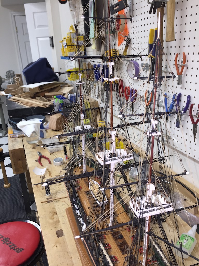
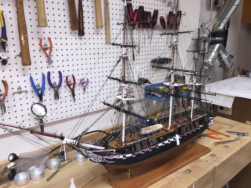
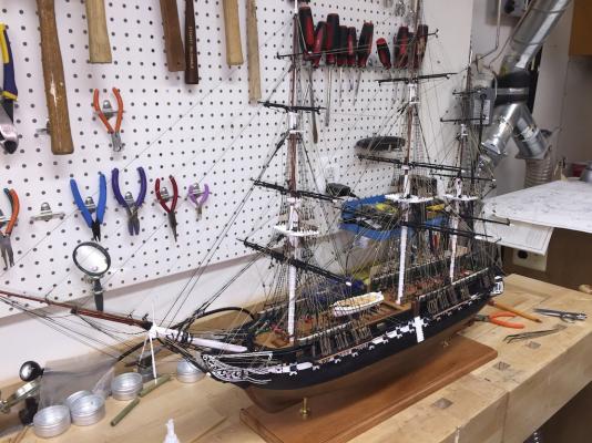
Progress on the Connie has been made. I am down to 7 pairs of running lines then I will need to make the coils and install them around the ship. I have completely exhausted the line I received from Mamoli in the sizes required. I have an order on the way from Syren Ship Model Co, (thanks Chuck). As soon as it arrives I will be able to complete the rigging. I am liking the way the ship is looking. Mamoli's instructions for the rigging has been pretty good. Once I learned how they were denoting everything, it has been pretty smooth. Here are a couple of shots of the ship as it sits on the bench today. I think tomorrow I will start working on the ship's boats since I can't do any more rigging other than installing a few blocks, until I receive the new rope.

- 335 replies
-
- 10
-
-
- Constitution
- Mamoli
- (and 3 more)
-
There are a number of sanding stations that can be purchased from wood working stores that allow you to place the object to be sanded on them and hook up a vacuum system to is and the dust is pulled down and into the vacuum. They come in various sizes and can be hooked to any type of vacuum system. Central home vacuum systems would not produce the flow necessary to move large amounts of sawdust through them. They are designed for household dust. That said, there are a number of companies that do provide dust control systems. The shop vac is a good start. There are internal foam filters that can be added to the vac that captures the finer dust particles. Up from there are mobile systems that have large bags to capture and filter the dust. These have more airflow than the shop vac and are generally less noisy, although still pretty loud. They come on rollers and can be moved through the shop to connect to tools and needed. The bags come with different filtering capabilities. These also can have a small cyclone system added to them to drop the heavier dust onto garbage cans although it makes them less portable. The next step up is a a full cyclone. This mounts to a wall and is stationary. Ductwork is piped from it to the various tools. The cyclone is an expensive option, but can really move the dust and drops it into a container that can be emptied as necessary. All of these systems move dust as it come the source. These are connected to the dust ports on the tools so al dust is moved through the tool. There is however another source of dust that needs to be accounted for. That is the dust that is thrown from the tool as the blade spins. This becomes and ambient dust that none of the above systems will collect. Some tools are worse than others but any tool used will produce some dust that is not collected in the vac system. For this, there are ambient dust collectors that are basically boxes with filtration material in them. Internal fans pull ambient air through the filters and clean the air. So these recycle the shop air and filtrate as it does so. These also come in different sizes depending on the size of your shop and how much air you want to turn over. If you are able to just open the door of your garage then a strategically situated fan can take care of this. If your shop is buried in the basement of your house, then you need to take care of it through the vacuum and ambient filter systems. You can spend a lot on dust control but it is important. Inhaled dust can cause long term health issues. Just like secondary smoke, uncontrolled dust can affect others in your house if left unabated.
-
Actually i made the Jacobs ladders off the ship then rigged them onto the masts. Iit was much easier to make them n a jig. There is one hard rung at the top to keep the ladder in shape. Otherwise the sides collapsed once they were pulled tight since the top is tied to the mast tip. A hard rung at the top then i used the same threads as my ratlines. Once it was completed i looped the top over the mast, drill holes im the cross trees and pulled the ends through and glued them. These weren't on the plans but were certainly part of the ship. Otherwise, there ws no way to get to the top.
- 335 replies
-
- 1
-
-
- Constitution
- Mamoli
- (and 3 more)
-
It is a stripper. You insert your knife into this holder and it will guide the blade. I never tired using it and totally forgot about having one until I saw your message. Maybe it will work well. I will have to try it.
- 1,756 replies
-
- 1
-
-
- constitution
- constructo
- (and 1 more)
-
At least some, if not all, are available on line for free at http://www.history.navy.mil/USSCTour/FileReference.html.
-
I wonder when those plans will be made available to the public?
-
Of course the Navy plans and the AOS plans do not have bulkheads. You would need to decide where you wanted yours to be and draw them out based upon the Half breadth, Sheer, and body plans.
-
If you are looking at actual plans for scratch, you could also look to the Anatomy of a Ship for the Connie.
-
The plans on the Navy Site were for the 1927 refit.
-
The other option is to add the futtock staves,then catharpins across, either one, or one for each futtock shroud pair. I did the single for the mizzen with the bentinck shrouds fore the fore and main. Mine actually never hit the deck since the ring is in the waterway. The fore mast set took some fishing to get strung, but otherwise everything is up in the rigging.
- 1,756 replies
-
- 1
-
-
- constitution
- constructo
- (and 1 more)