


usedtosail
-
Posts
2,421 -
Joined
-
Last visited
Content Type
Profiles
Forums
Gallery
Events
Everything posted by usedtosail
-
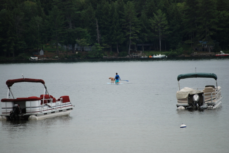
 Yeah, Jay no room for a gun there. Still working on the hammocks and cranes. I have the port fore side cranes filled with hammocks and netting. I just need to finish trimming off the netting above the rope. I used white glue to glue the hammocks and netting to the rail, and the netting to the line. This worked really well. I'll have pictures when I get the netting trimmed. I have to make a new batch of hammocks from Sculpey as I used mostly all that made for this one set of cranes. Speaking of pictures, I hope you don't mind me taking a detour on the build log to show you probably the most amazing sunset I have ever seen. I took these at our condo on Newfound Lake in New Hampshire last week. And here is me, my daughter, and my lovely wife, so you can put a face to the name. And this just cracked me up when I saw this guy and his dog paddeling by. It was very serene. Enjoy.


- 1,354 replies
-
- 12
-

-
- constitution
- model shipways
- (and 1 more)
-
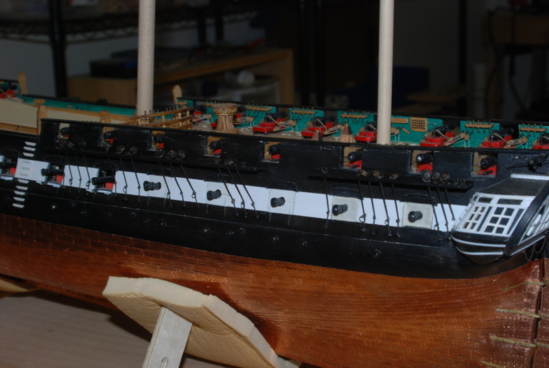
A small update regarding the hammocks and hammock cranes. I have been gluing up groups of 6 hammocks to go between the cranes. It looks like I will need about 8 of these sections to fill each side in the front cranes. I drilled holes and glued in the fore cranes after carefully cutting them out of the sprue, cleaning and blackening them. I had to open up the holes with a #80 drill bit in a pin vise after blackening as the process closed them up some. This would have been a lot easier if I had done it before installing them, but I was able to hold a small piece of wood behind each crane and drill the holes open while they were in place. I threaded .008 thread through the cranes and tied them to the tiny eye bolts on the hammock boards. This took a little bit of time as I had to keep applying thin CA glue to the end of the thread and trimming it at an angle, to get the thread through the tiny holes. I had to cut the end after just about every hole. Getting the thread through the tiny eye bolts was actually the easy part. I have dry fit some netting and hammocks into the starboard side cranes, but they need to be glued down to look right. They are a bit inconsistent too, which I am not crazy about. It remains to be seen if I use them at all, or only some, or fill them all in. Lots more to experiment with. I have also been thinking about the lines that will go across the open waist. I was going to try to make stanchions for these but didn't have a good method. I decided that it would be better to buy some instead, so I ordered some from Billings. We will see how they look but I am pretty sure they will look better than anything I can make.

- 1,354 replies
-
- 6
-
-
- constitution
- model shipways
- (and 1 more)
-
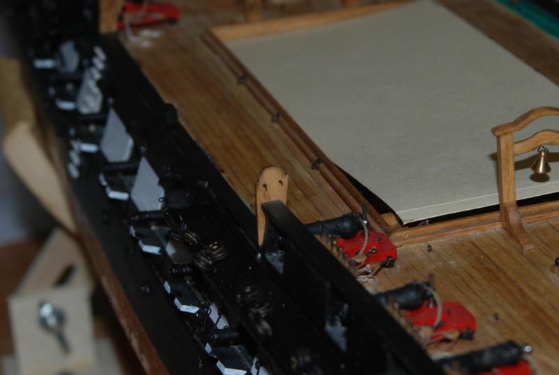
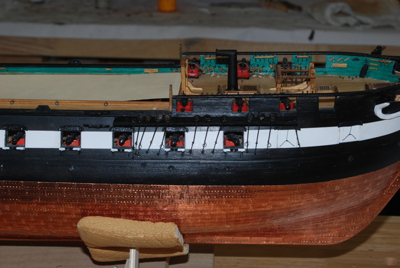
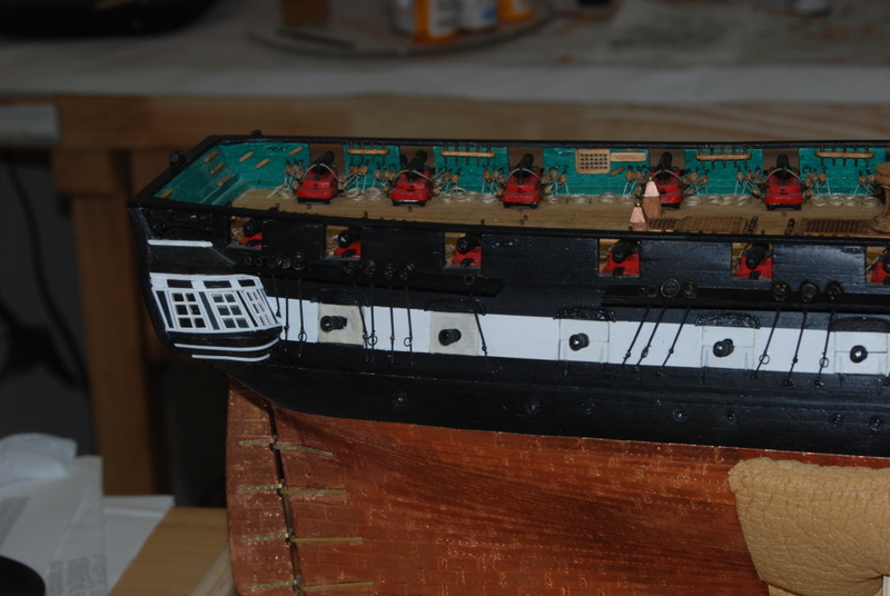
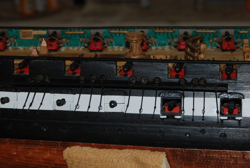
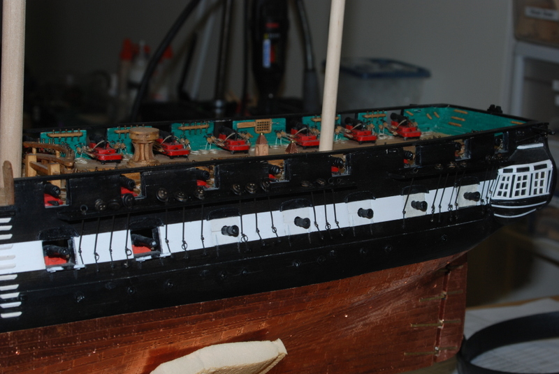
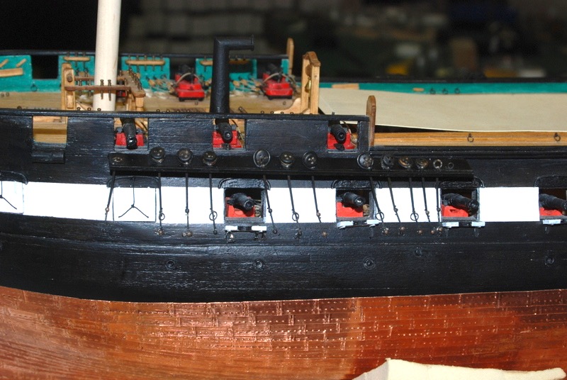
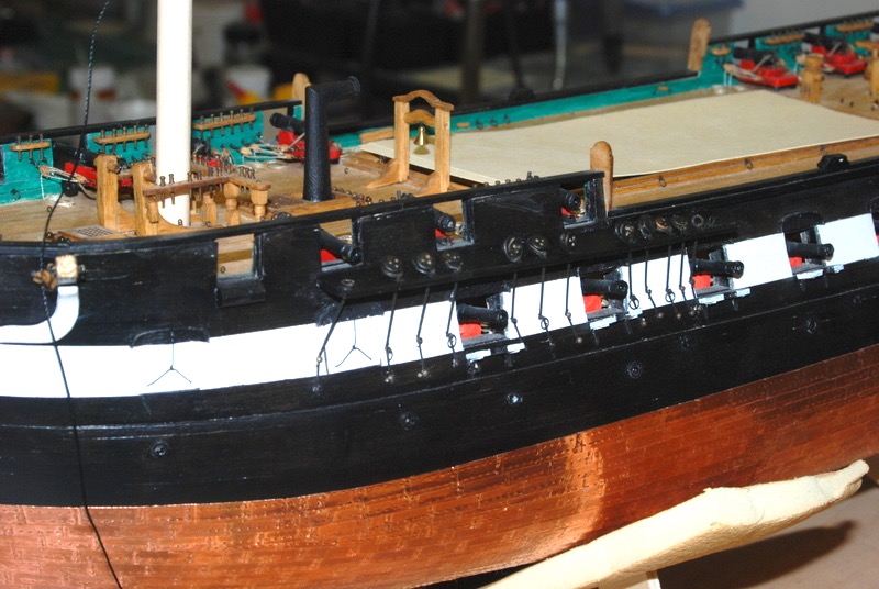
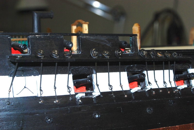
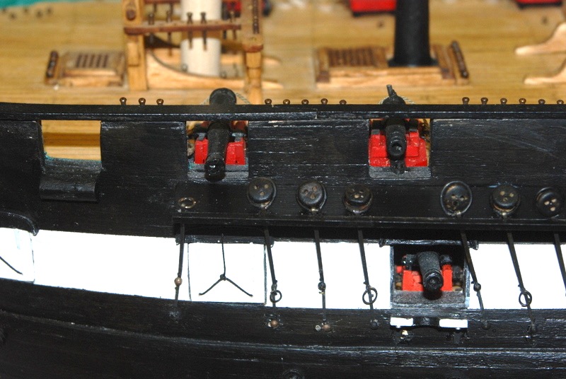
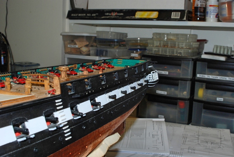
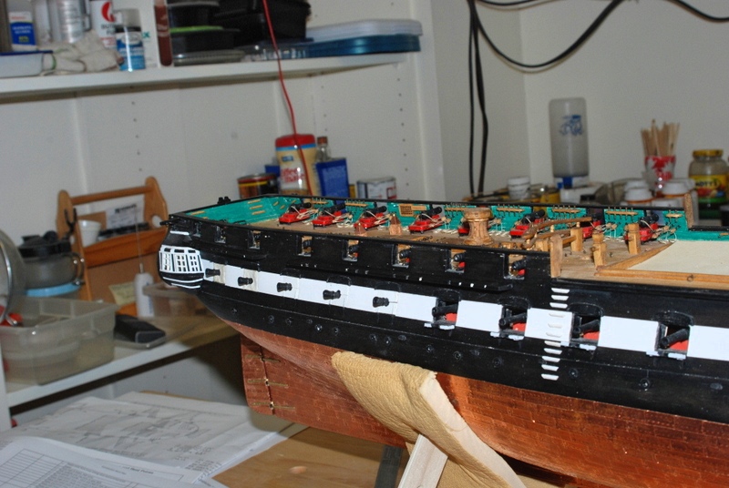
Thanks Jay. I am following your lead on this model as yours came out so well. As I have mentioned in previous posts, I am modeling the 1812 configuration as much as I can. I am using these conclusions from the Naval historical command regarding port lids: In conclusion, in compliance with the mission of the Naval History & Heritage Command Detachment Boston which includes in part, “ensur[ing] material compliance and documentation with the historic requirements of [Constitution], maintaining [the ship] as close to its 1812 configuration as possible,” 19 [emphasis added by author] the gun port lids of USS Constitution should be as follows: 1. Adapt the half ports presently found on Constitution: A. Retrofit the upper half port so that the lid is completely removable, but so that it can be secured in the port with bolts (see suggested illustration below, showing a type of port lid bolt)20 B. Retrofit the lower half port lid so that the lid drops to 90° and projects outward from the hull of the ship Substitute two single gun port doors on each of the two forward-most ports in the bows of Constitution Retrofit the two aftermost ports, at the captain’s great/forward cabin with canvas, as per the sail plans and artwork depicting such configurations on Constitution, Congress, and President As you can see, the two forward most ports had single doors according to this research, so that is what I built. I have also added the canvas covers on the rear ports. If you look close you can see that there are no top lids on the open gun ports, as these would have been removed.
- 1,354 replies
-
- 3
-
-
- constitution
- model shipways
- (and 1 more)
-
I can't believe both those boats came from the same parentage. You are a master at modification, my friend. Great job!
-
I just saw those on the Model Expo plans recently. I think they said they held life lines. I am not sure in what era they were added to the ship though.
-
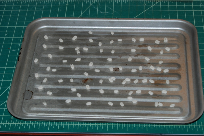
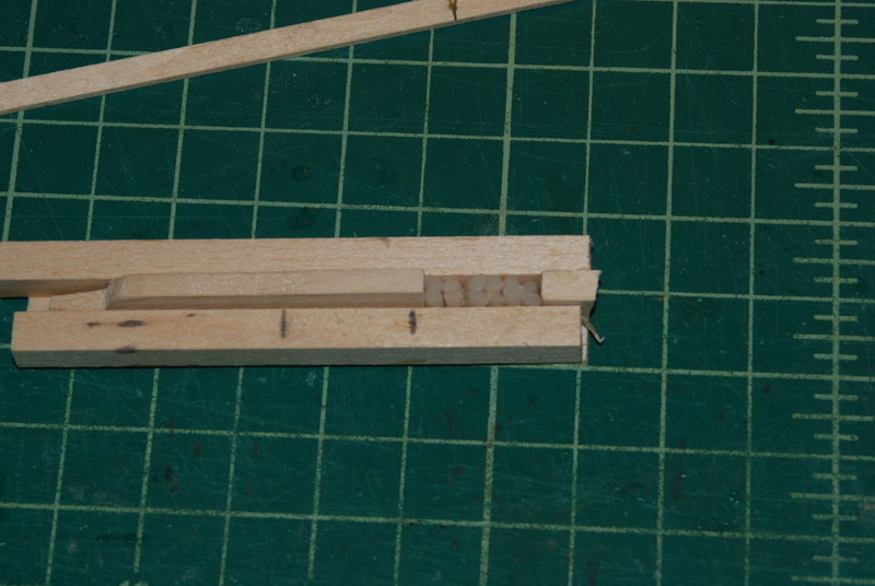
Thanks for the likes everyone. First off, here is a picture of the first batch of hammocks. These are made from an off white Sculpey material rolled out to about 1/16" thick, cut to 1/2" length and folded in half. While they were baking, I made a jig to make it easier to hold them together during gluing. I am making them in 3/4" sections of 6 hammocks each, which will fit between each crane. I glued the first group together upside down, so when they are dry I can sand the bottoms level with the jig to even them out. My hope is that the tops will be level when I take them out. I also drilled holes into the hammock boards to take those tiny eye bolts that I made. The boards off the model were a lot easier to do then the ones already installed. I lost quite a few in the process, especially adding them to the boards already on the ship, but I had made enough spares to finish without having to make any more.
- 1,354 replies
-
- 10
-
-
- constitution
- model shipways
- (and 1 more)
-
Thanks for the plans Jon. I do plan to use the photo etched frames that came with the kit. They are a bit two dimensional but should look OK with everything around them. I made over 70 hammocks from Sculpey last night, which should be enough for about 6 inches of rail. I will experiment with gluing them together tonight. No photos yet.
- 1,354 replies
-
- 2
-
-
- constitution
- model shipways
- (and 1 more)
-
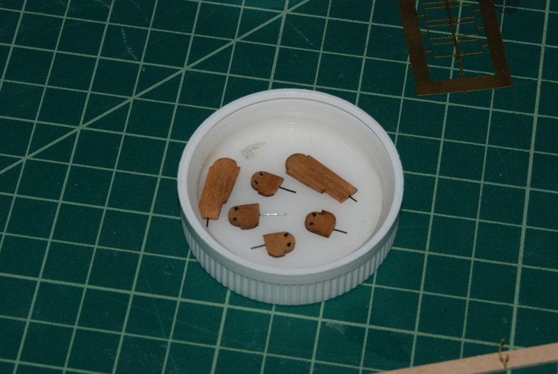
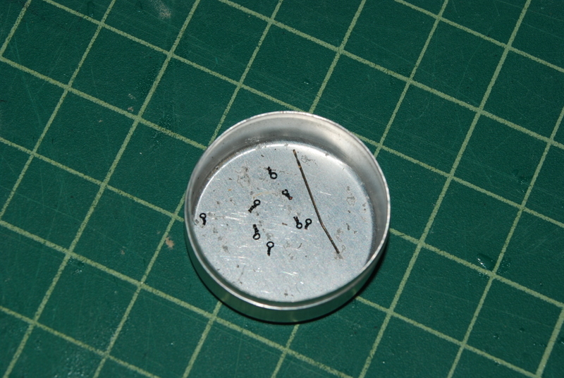
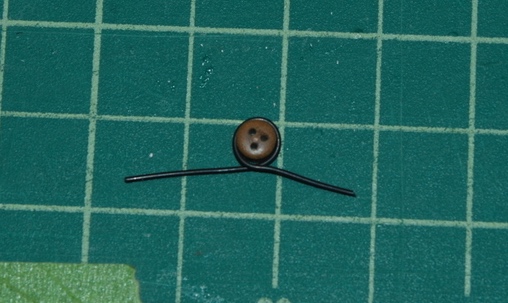
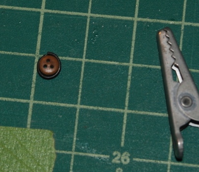
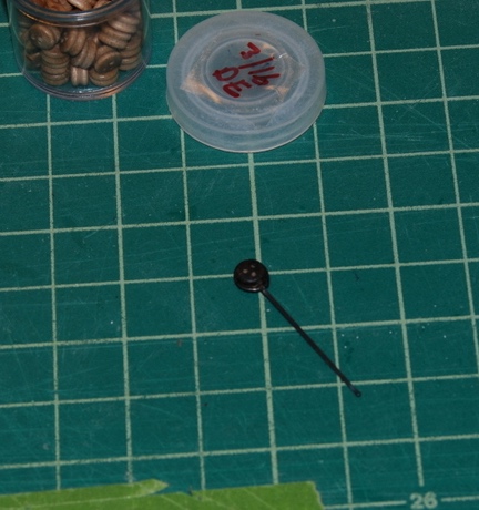
I need very small eye bolts to take the ends of the lines running through the hammock cranes. These attach to the hammock boards which are very thin. So, I tried my hand at making some. I first tried some steel wire but could not get them small enough, then I found some 30 gauge artistic wire that I had bought for another project. I put a U shaped piece of wire into a pin vise then SLOWLY wrapped it around a #78 drill bit. You have to go slowly to avoid breaking the wire. That's the drill bit in the picture. These are by far the smallest eye bolts I have ever made. I drilled a hole into a hammock crane to test them, and placed one in without any glue. I was able to thread some line through it and tie it on and it all seemed pretty solid, so as long as I can manipulate them, which is pretty hard since they are so small, I should be good. I had to make about double the number I kept because of breakage or lossage or it just didn't look right, but it did not take too long. I have half of what I need but I am going to make a bunch more just in case.
- 1,354 replies
-
- 9
-
-
- constitution
- model shipways
- (and 1 more)
-
Wow, that pile of frame pieces really put this project in perspective. Someday I hope to tackle something like this. You are going a fantastic job.
-
Just a quick update on my last post. In between doing a major cleaning of the workshop (I can only stand so much clutter and dust) I did play around with making some Sculpey hammocks. The sizes seem about right and are not too hard to make, so I am pretty sure this will work. I also set up a small test rail with a couple of the hammock cranes to test the whole process before trying it on the model.
- 1,354 replies
-
- 3
-
-
- constitution
- model shipways
- (and 1 more)
-
Thanks Captain Steve. Those were some good posts. I don't know how I missed them. Now for the problem. If the hammocks are 18" wide in the real world, that converts to about 6mm at the scale of this model. Once the hammocks are folded, they would be less than 3mm tall, and about 2.5mm wide. That is very small and I think too small to look right in the hammock cranes. I may have to make them a bit bigger, but I will try them at this size first. This could be a fun challenge or a total PITA.
- 1,354 replies
-
- 2
-
-
- constitution
- model shipways
- (and 1 more)
-
Thanks Popeye, and for the other likes. I finished up the channels and deadeyes on the starboard side last night. I am glad I started on the port side, because I was able to get these to look better (more lined up) after practicing on the other side. I am glad this part is now done as I found it a bit tedious. But as with everything I am glad to have done it. I am at a bit of a crossroads now. I have been vacillating about whether to do the hammock cranes now or wait until after the rigging, but after looking things over last night, I have decided to add them now. I am going to try to make Sculpey hammocks to go in them too. I think they will be low enough to not interfere with the rigging later on. I am also going to add the quarter and stern davits now, but haven't decided when I will make the ships boats. I was going to do them after the hammock cranes, but now I am thinking that I want to get the bowsprit and masts built next. BTW - does anyone know off hand what length the hammocks would have been in real life? Somewhere in the back of my mind I am thinking 18" but I am not sure. I probably have it somewhere in my notes, too.
- 1,354 replies
-
- 6
-
-
- constitution
- model shipways
- (and 1 more)
-
Model Expo 1/2 money back if built in a year??
usedtosail replied to WEHarlow's topic in Wood ship model kits
That guide book for the Sultana is an excellent practicum written by our own moderator Chuck. It makes a very nice model. -
That is a sweet paint job Popeye. What a difference weather wise from last weekend. I hope the rain holds off for you for the rest of it.
-
Thanks popeye. You're right about the speed of the build. I am having fun, although last weekend I was stuck in the cold and rain of NH when I would have liked to have been in the shop. Oh well, we still had fun. Just a quick update. The port side channels are all finished with their chain plates and backing links (I have been calling them chains and plates, which is not right). I have also touched up all the areas around them with black paint, which does hide a multitude of sins as popeye said. My goal is to someday build a model with all natural wood, but I am not there yet. I have the starboard side channels in place and have stropped and painted all the large deadeyes for that side, so I can start installing them tonight. I still have to strop and paint some medium and small deadeyes, but only a few.
- 1,354 replies
-
- 8
-
-
- constitution
- model shipways
- (and 1 more)
-
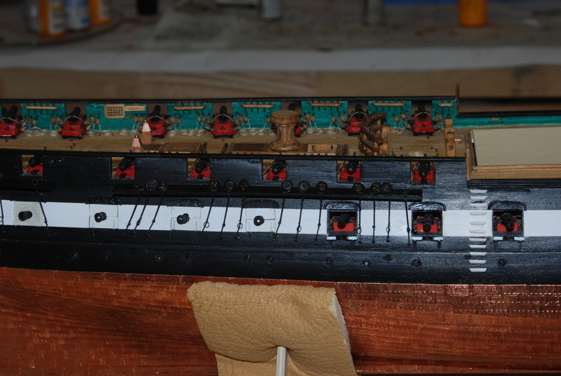
Thanks Nenad, Steve, Al, Geoff, and David, and the folks who hit the like button. I feel bad for not having an update in a while, but I haven't been home much and when there I have had to deal with other things. But, I am back in the shop for a bit this week so I was able to make some progress. I have been working on the process of stropping the deadeyes and attaching them to the hull with the chains and plates. I wanted to go through the whole process with one channel to make sure it was going to work before totally committing to it. So, I started with the port fore channel to see how this would work. I first stropped the large and medium deadeyes I would need for this channel. I tried first using a copper wire, but it was too soft and I didn't like how easily it bent. So I went back to the 24 gauge black steel wire that I have used many times before. I first wrapped the wire completely around the deadeye, but with a small piece of brass strip where the two wire ends crossed. The strip was to make a small space so that I could slip the end of the chain between the wire and the deadeye later. I then cut the two wire ends at the same place, making a loop with a small space under it. I tried soldering the ends together at this point, but I could really only get the soldering iron on one end of the wire which didn't heat up the other end, so the solder joint was pretty lousy. Also, the soldering iron was scorching the deadeye. A little scorch would have been OK since I was painting them black later, but it was too much. I thought of trying silver soldering but I was really afraid of setting them on fire! I settled with just a tiny drop of medium CA glue that I applied right at the joint. It actually flowed nicely into the joint like a good solder would and the bond seems very strong. I could have also added more glue to glue the deadeyes to the strops, but I wanted to be able to rotate the deadeyes in the strops to get the holes to line up correctly later. I used the alligator clip to hold the deadeye by the sides when I glued them, which forced the two ends of the wire together. I then painted the deadeyes and strops black. One thing I found with this method was to make sure the holes in the deadeyes were lined up correctly with the joint because after painting them I could not easily rotate the deadeyes in the strops. I had to take a couple of them apart to get the holes right after painting, but now I make sure the holes are lined up correctly before painting. I blackened some chains and plates, some rings, and some nails that I had that will fit through the holes in the chains and plates, after I opened then up a bit with a #72 drill bit in a pin vice. I drilled out the holes while the chains and plates were still on the brass etched plates, so they were easy to hold. i also made up some eyebolts with rings, which are used in place of nails at the ends of some of the chains. To attach the stropped deadeyes to the channels, I first marked the line that the chains make on the hull with some masking tape, to try to get them to line up nicely. I also added a dowel for the fore mast and marked on it where the ends of the fore shrouds would be and tied a piece of line at that height. I then slid a chain down through each hole in the channel, set the end at the masking tape and used tweezers to hold it at the top of the channel. I then carefully removed the chain and bent it 90 degrees at the tweezers, pushed this bent end through the gap in a deadeye strop and bent it the rest of the way back onto itself, covering the joint in the strop. I used the same procedure for the rings that are attached with chains. I was then able to slid the chains back into the channels, pull them down so the strop was at the channel, and drill a hole into the hull, again using the string on the mast to get the right angle for the chain. I added a plate to a nail or ringbolt, cut off the excess length of the nail, pushed it through the hole on the end of the chain and into the hole in the hull. I put a small drop of medium CA on the nail shaft before pushing it all the way into the hole. Before the glue dried, I positioned the plate to be in line with the chain, then after the glue dried I drilled another hole in the hull for a nail through the bottom hole of the plate. Here is how they came out. There was a little collateral damage during the process, like having to reattach the first gun port lid in the pictures, but nothing major. I still need to touch up the black paint on the nail heads and a couple of other areas. There are also a couple of extra holes that need to be filled where I didn't have thing lined up quite right. I glued the fore main and mizzen channels to the hull last night, so they will be rigged next.

- 1,354 replies
-
- 10
-
-
- constitution
- model shipways
- (and 1 more)
-
Nice milestone Ken. She looks great.
-
David, your chains are looking great. I am just about to attempt this step on mine and I must say it is pretty daunting. I did find some nails that I had that are just a little oversize, but I was able to enlarge the holes slightly in the chains and plates, and I can chuck the nails in my Dremel and file them down to fit into the enlarged holes. That is the plan for now anyway.
- 117 replies
-
- 3
-
-
- constitution
- model shipways
- (and 1 more)
-
I slide the back edge of the blade across the tape.
-
I have used the back of a hobby knife blade with good results.
-
It has been a while for an update but I have been working albeit slowly. I finished the channels and painted them black, then added pins to them to reinforce them on the hull. Here they are temporarily in place. I will be adding the lower deadeyes to these before permanently gluing them to the hull. They are pretty hard to see in those photos because of the black on black. I also finished the two fixed blocks I am adding to the waist rail. I made these from a single block of wood in the mill, using varying depths to simulate the sheave. Now I am stropping the lower deadeyes to get these all ready for the channels. Updates to come once I have the process nailed down.
- 1,354 replies
-
- 10
-
-
- constitution
- model shipways
- (and 1 more)
-
Cutty Sark by NenadM
usedtosail replied to NenadM's topic in - Build logs for subjects built 1851 - 1900
Wow, that looks great. You have done a fine job indeed.- 4,152 replies
-
- 6
-
-
- cutty sark
- tehnodidakta
- (and 1 more)
-
Cutty Sark by NenadM
usedtosail replied to NenadM's topic in - Build logs for subjects built 1851 - 1900
At the scale you are working Nenad I am really impressed that it has taken you this long to get one of those. Have fun with it, it should make your work a whole lot easier.- 4,152 replies
-
- 4
-
-
- cutty sark
- tehnodidakta
- (and 1 more)
-
Yes I think it would be. It is the only thing I have found that securely holds square chunks of wood in the lathe, too. The four jaw chuck does not work well for me, no matter how hard I tighten it the wood wants to move. I suppose I could turn a round spindle to the wood, then use that part in the three jaw chuck. Hmm I'll have to try that sometime. Thanks for the train of thought Geoff!
- 1,354 replies
-
- 1
-
-
- constitution
- model shipways
- (and 1 more)
-
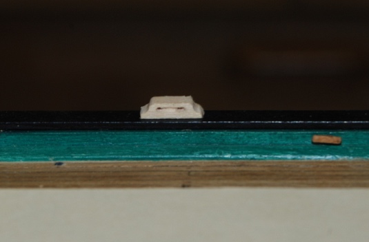
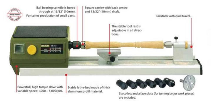
Hi Geoff. I am not sure what pedestal you are referring to because I didn't use the mill for the ships wheel. But, if it is the fixture shown in post 823 in the lathe and then in the drill press, that came with the Proxxon lathe when I bought it. It has holes in it so you can screw wood on from the back. Here is a picture of it from the catalog (lower right): If that is not it, let me know.
- 1,354 replies
-
- 1
-
-
- constitution
- model shipways
- (and 1 more)