


usedtosail
-
Posts
2,421 -
Joined
-
Last visited
Content Type
Profiles
Forums
Gallery
Events
Everything posted by usedtosail
-
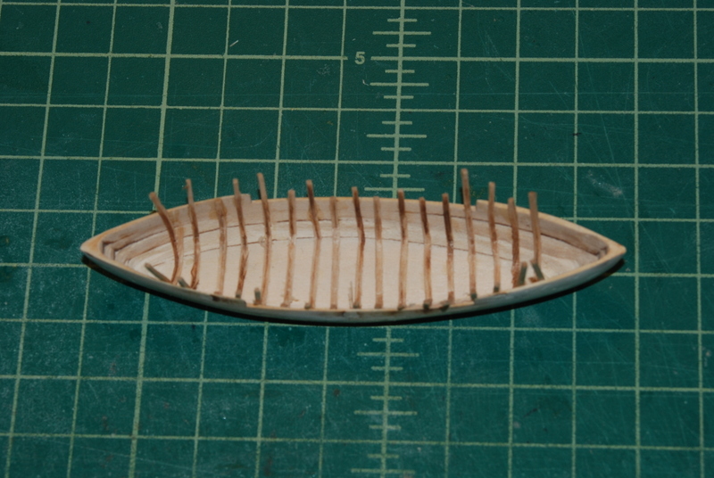
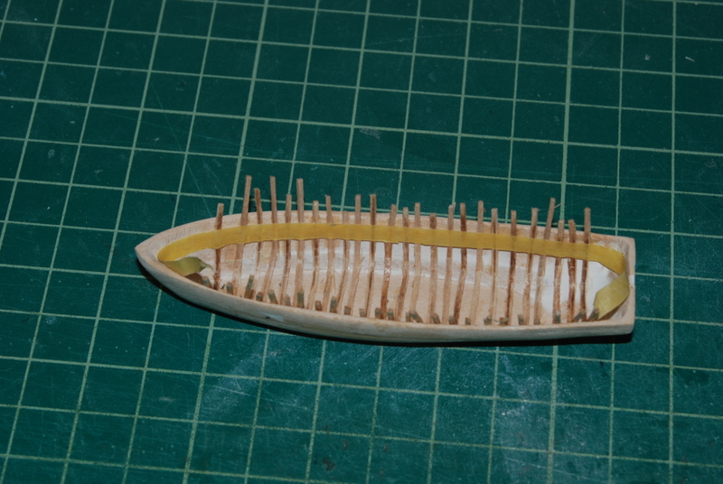
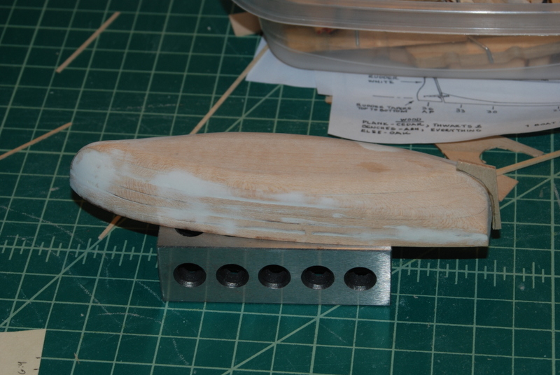
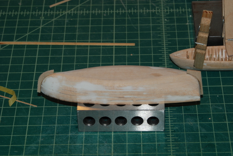
 For my friend Nenad, here are some more,closer up, construction pictures of the ships boats. Here is how they look after the ribs are all added: I then use tape to mark the tops of the ribs, and trim them off with a scalpel: Here is the larger cutter with the ribs trimmed: I am now in the process of adding the keel pieces. The bow and stern pieces I cut out of sheet material and cut the curved in on the scroll saw: Since these boat hulls will be painted I have used wood filler. The outsides have not yet been fully sanded. Once I prime them, I will probably need to do another round of filler and primer. I'll continue to document the process of making these as I go along.
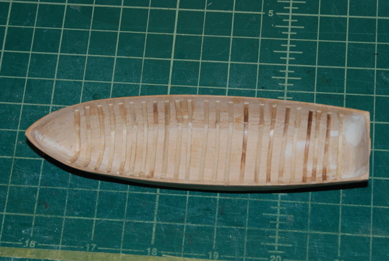
- 1,354 replies
-
- 7
-

-
- constitution
- model shipways
- (and 1 more)
-
Congratulations Popeye. That rain and lightning was something else last night down here too.
-
HMS Beagle by johnb72 - after 1831 refit
usedtosail replied to johnb72's topic in - Build logs for subjects built 1801 - 1850
Hi John. I look forward to following you along on this project. A few years ago I started with the Mamoli Beagle kit and modified as much as I could to match Marquardt's book. It came out OK, but a scratch build will be even better. -
Thanks all. Bill, I was lucky that my wife let me take over half the finished part of the basement after the kids moved out. It seemed like lots of space at the time, but I have slowly filled it up. Nenad - the boats are pretty ugly at the moment but I will take some close ups as I progress on them. I have the advantage of working at a much larger scale then you are, but I am sure yours will come out great based on the work you have done so far.
- 1,354 replies
-
- 1
-
-
- constitution
- model shipways
- (and 1 more)
-
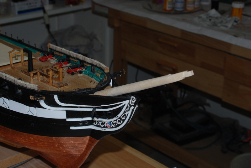
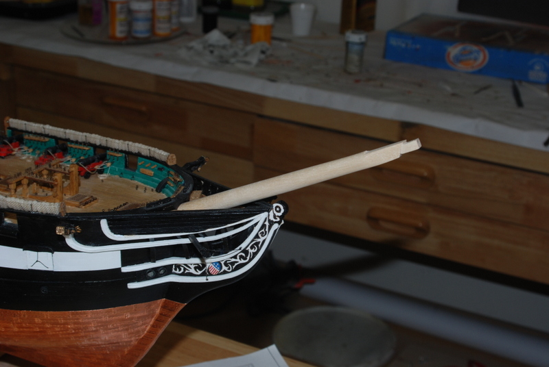
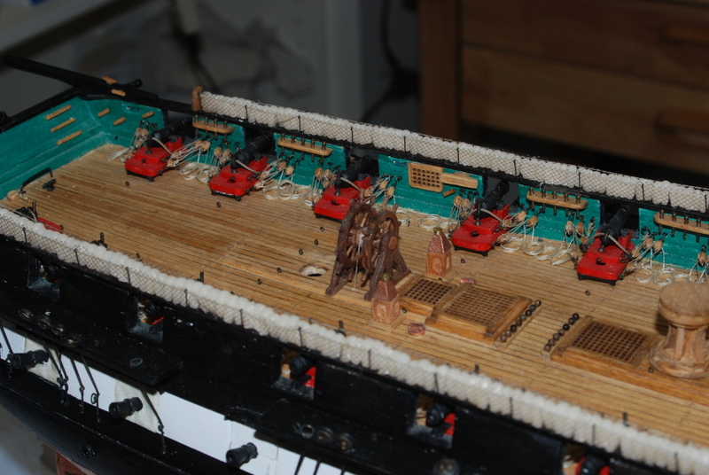
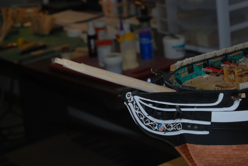
I am still adding ribs to the three boats, although all of the ribs are now in the large cutter. The others are taking more time because they are closer together so the width of the clamps limits the number I can put in at a time. In between adding ribs, I attached the ships wheel to the deck. I have also started constructing the bow sprit. It has a unique shape where the top is straight but the sides and bottom are tapered. This makes it a bit harder to shape on a lathe. My approach was to sand a flat into the bottom to get the taper, then hand sand the edges to start rounding them out, then put it in the lathe and sand it to finish rounding it out. I think this worked pretty well. I used the mill to shape the square section at the front, then the tenon for the cap. This has always been challenging to me to get these square sections to come out, well, square, but with the mill this was a lot easier. I am working out how to make the stairs on the mill too and will show how I end up doing it in a future post.
- 1,354 replies
-
- 10
-
-
- constitution
- model shipways
- (and 1 more)
-
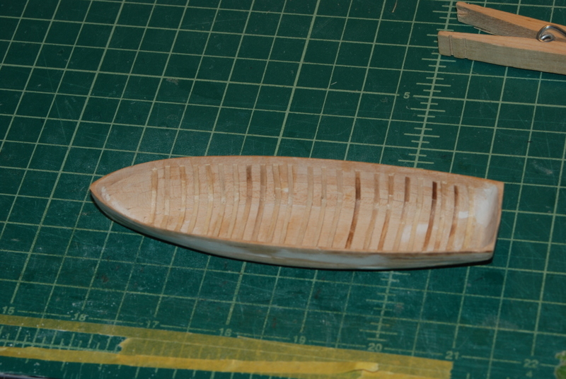
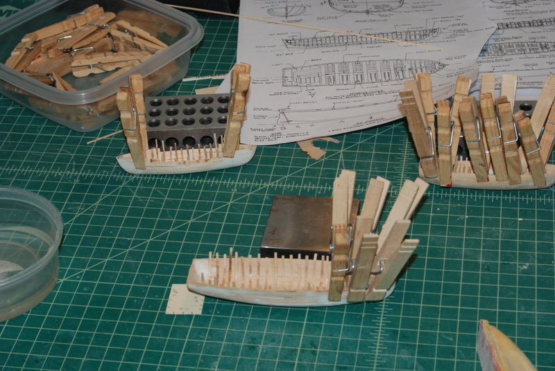
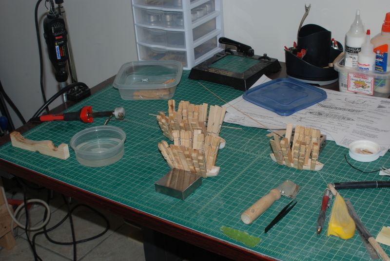
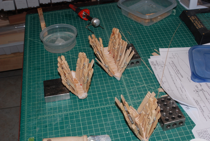
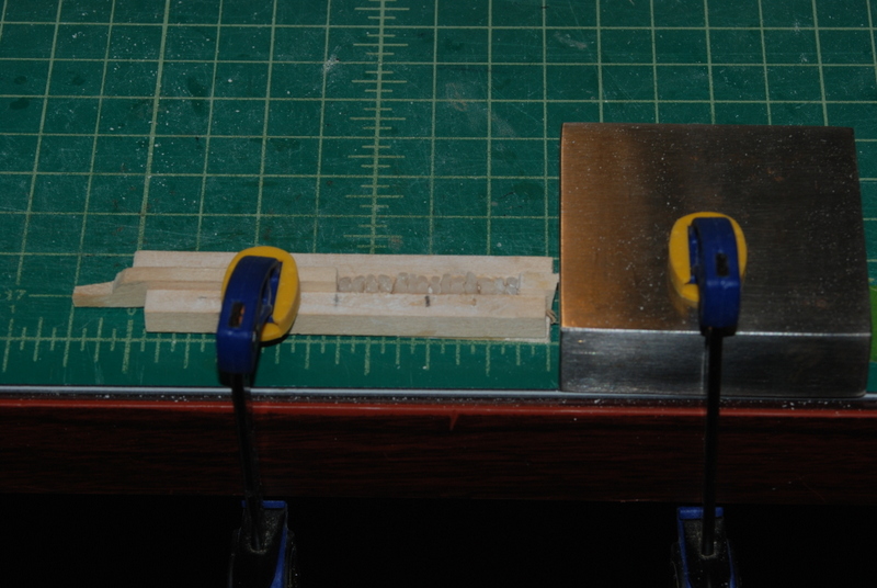
Some progress since the last post. I managed to get all three boats roughly shaped inside and out. I did more shaping on the inside, and now I am in the process of adding the ribs to all three. They are very thin, so I am hoping that the ribs will give some support before doing the final fairing of the outsides. I will then paint them white, except for the rails, and then add the natural wood details of the interior. I soak the ribs and bend them with the electric plank bender in the picture, then place them inside the hull and clamp then while they dry. The next day or so, I then glue them in place and again clamp them in with clothes pins. Here are a bunch drying after bending, with some already glued in.
- 1,354 replies
-
- 6
-
-
- constitution
- model shipways
- (and 1 more)
-
Wow, that will make these even more complicated. Great work on these brass rails Ken. They really add a lot of detail.
-
Thanks guys. Popeye - those templates aren't centered or glued down yet to the wood pieces, so they fit much better than you see in that picture. The only part that is missing is the very ends of some of the tabs, which are only there to locate the slices while gluing. The bottom tabs I don't really care about as I will just center it after carving out the interiors of the glued u p slices. I do have sheets of basswood that I can use if I need to make any new slices.
- 1,354 replies
-
- 2
-
-
- constitution
- model shipways
- (and 1 more)
-
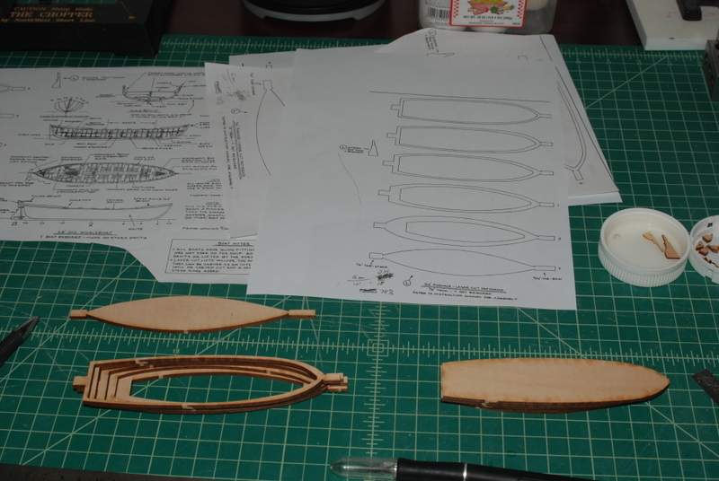
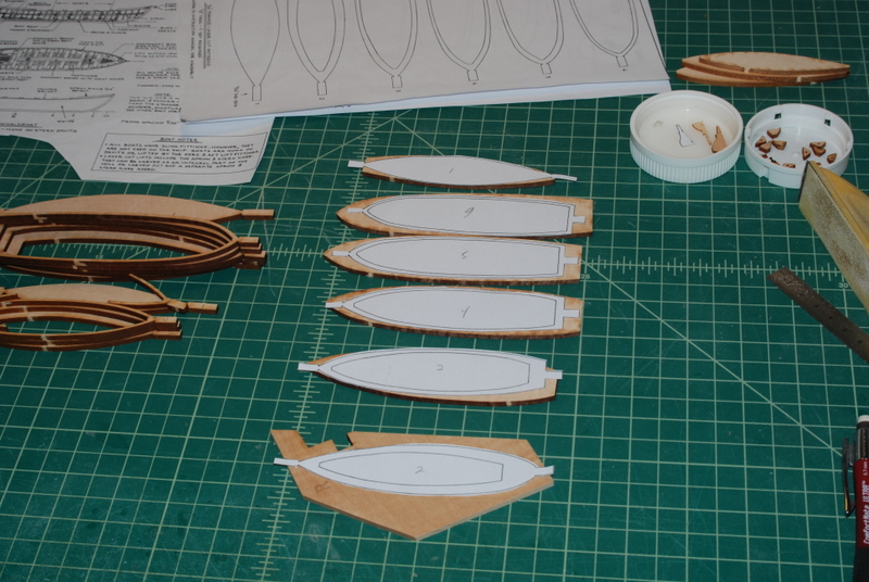
I have finally finished with the hammocks and netting. I cleaned up the aft port side last night. Now on to the ships boats. As an aside, while gathering up the ship boat parts I found the laser cut quarter davit brackets supplied with the kit. No where on the plans do they show these as laser cut that I could see, which is why I made them myself in the fist place. They do look better than the ones I made, so I may clean them up and paint them. It will be a while until I need them, though. For the ships boats, I want two boats on the open hatch on cradles and one hanging from the stern davits. I do not want to put any on the quarter davits. In sources I read (Bainbridge's book, I think) it stated that in 1812 it didn't have whale boats, as they were bought in 1813. I will use the supplied gig whaleboat for the stern davits though, since I think the supplied parts will make a nice looking boat. I will also use the 36' cutter supplied parts for the bottom boat on the waist beams. For the top boat, I want a 28' cutter, so I shrunk the plans for the 36' cutter. After cutting out the centers of the 36' cutter pieces, I realized I could use these centers for most of the 28' cutter pieces. I have one piece more than I do centers, but there was enough wood left on the laser cut board to make that last piece. It looks like the bow and stern pieces of the keel are to be carved out of the laser cut pieces at the same time as the hull is thinned down, but I may end up making these as separate parts and adding them to the keel. I am pretty sure I will have to do that on the 26' cutter because the tabs are pretty small on a few of them.
- 1,354 replies
-
- 7
-
-
- constitution
- model shipways
- (and 1 more)
-
How can you tell, Popeye? Not one of my finest creations, but it does the job. Thanks for the nice words, too.
- 1,354 replies
-
- 1
-
-
- constitution
- model shipways
- (and 1 more)
-
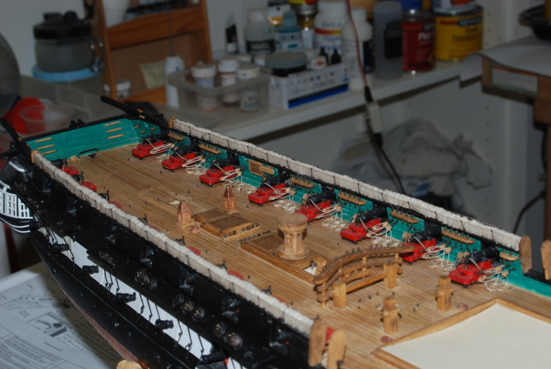
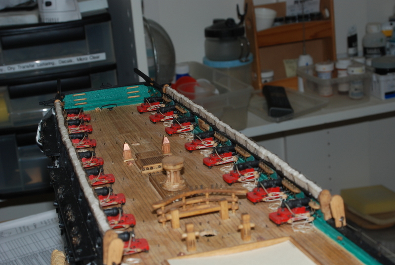
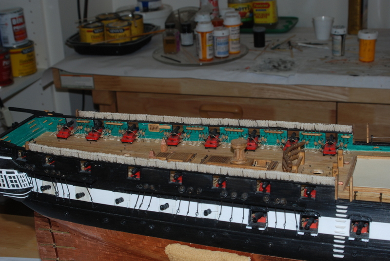
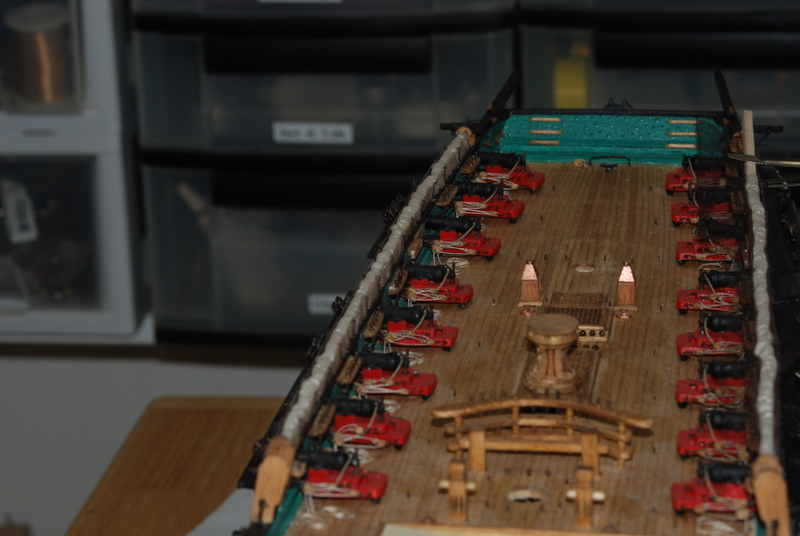
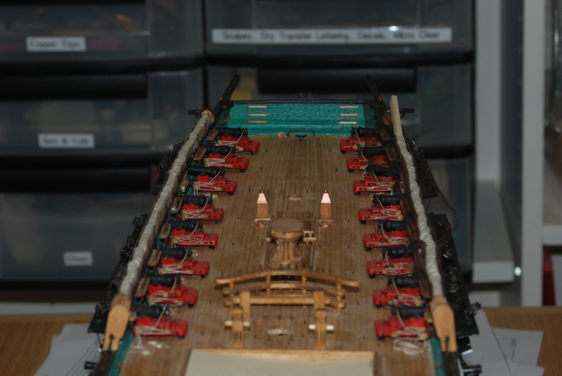
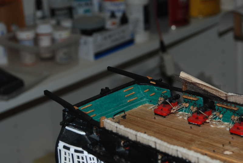
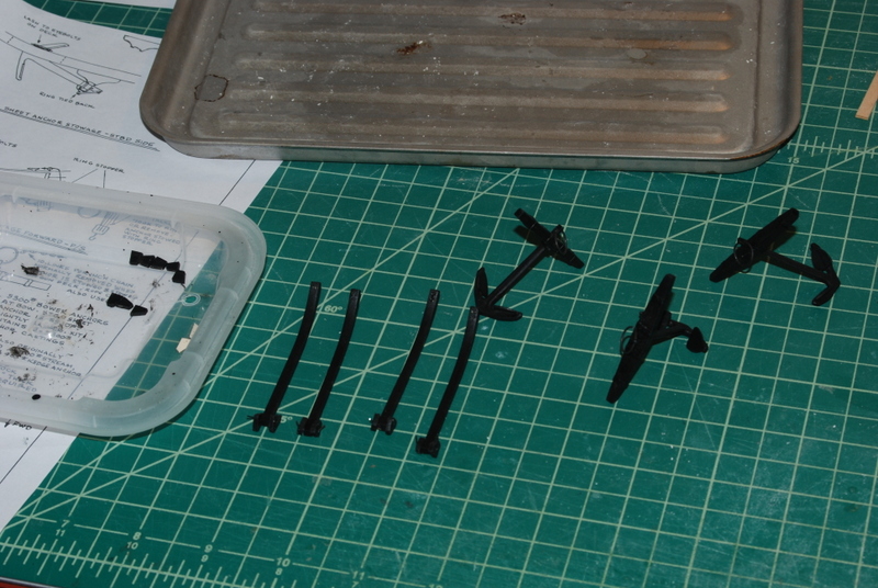
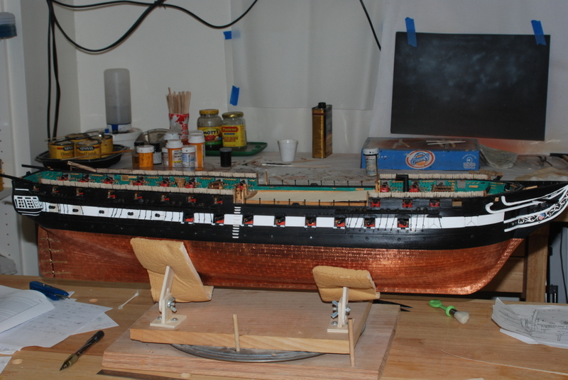
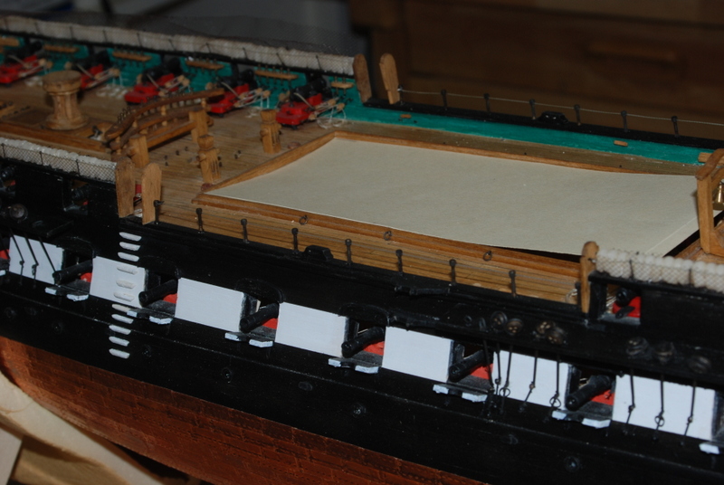
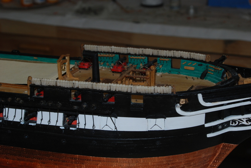
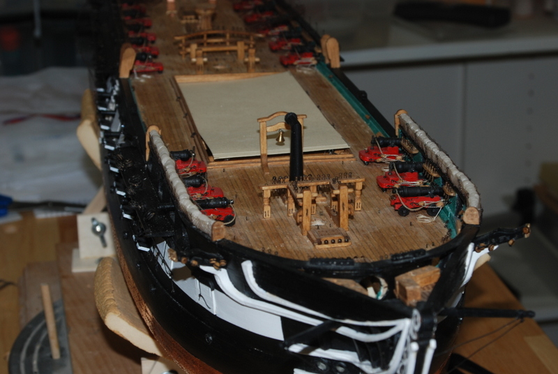
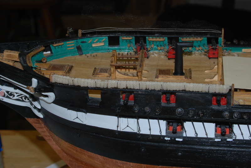
Thank you Bill and the others for the likes. I haven't provided an update lately, mostly because I am in the middle of a bunch of things - still making hammocks and filling the cranes, making anchors, and making the stern and quarter davits. I did complete the stern davits and added stanchions and lifelines to the open waist. So here are some pictures of where I am as of last night. Starboard aft cranes filed with hammocks and the port side almost done: Stern davits: Anchors and Quarter Davits: Waist Rail: Complete side view: Once I get the hammocks finished, I will make the ships boats, then start on the spars and rigging. I will hold off installing the anchors, quarter davits, or ships boats that go on the davits until after the rigging is complete.
- 1,354 replies
-
- 7
-
-
- constitution
- model shipways
- (and 1 more)
-
I enlarged the holes with a drill bit while they were still on the brass sprue, which worked well for me. I like the way you tucked the end of the chain plate into the notch with the deadeye stropping.
-
Nice work on the chain plates and deadeyes Ken. If you are like me, you will be happy when these are finished.
-
That is a nice looking boat, Jay. It looks like a lot of fun. I have gone ahead and added an index to the first post, so now I just need to keep it up to date as I add new stuff. At the rate I am going, that shouldn't be too hard.
-
Thanks very much Jay. I have used your build log for ideas and inspiration as well. I used to sail and race a 16' Hobie Cat. When we had kids I found it was better to get a small power boat, which I named "Usedtosail" because I was more used to sailing. I am on my third power boat now, a 22' Chaparral bow rider which I have had for 13 years. I had a Sunfish for a while when the kids got older but sold it. I would love to get a small sail boat like a Laser when I retire in a few years.
- 1,354 replies
-
- 2
-
-
- constitution
- model shipways
- (and 1 more)
-
Thank you rdestefano01. There is a lot there to go through, I realize. I should add a table of contents like some other build logs have, since it is getting pretty long.
-
Lost voices from HMS Guerriere: Court Martial testimony.
usedtosail replied to uss frolick's topic in Nautical/Naval History
What do you think they mean when they talk about the "gangways" on the Constitution? Wasn't it always a single spar deck? Is there some other meaning for gangway? Thanks. -
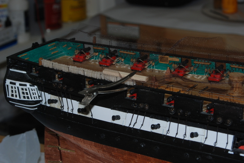
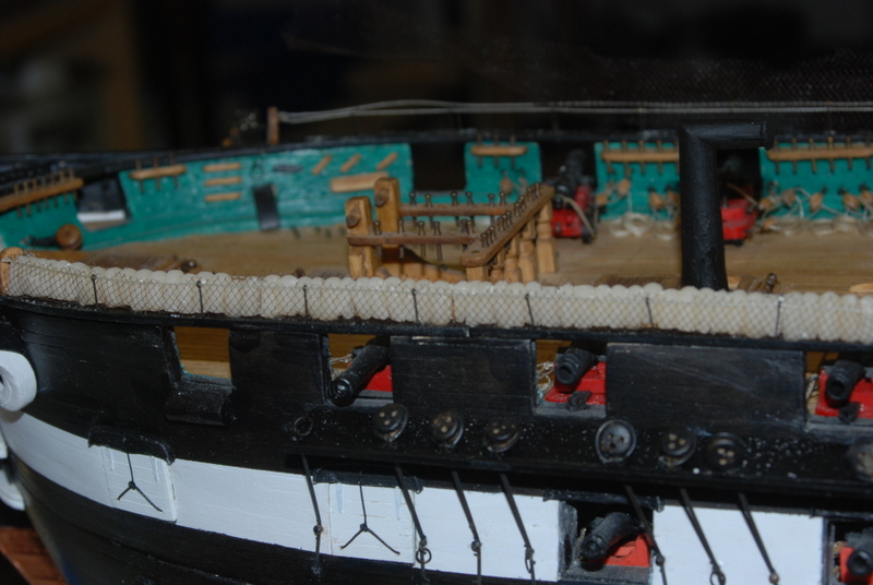
Work continues on the hammocks, cranes, and netting. I finished adding hammocks to the the starboard fore cranes, and trimmed the netting, so the fore cranes are completed. I have the lines threaded through the aft cranes and have started to fill the aft starboard cranes. I have some room to clamp these through the gun ports, which means I don't have to hold them until the glue sets. I am using wood glue to glue the Sculpey hammock sections to the rail, with the netting sandwiched between the hammock sections and the rail. After I fill all the cranes, I brush some wood glue along the lines and netting, then trim the netting at the lines with some very sharp clippers. Here is the jig being used to make up sections of hammocks. It also lets me sand the bottoms level while still in the jig. I still have a lot of hammocks to make but progress is being made, and I am able to start on other items like the stern davits in the mean time.
- 1,354 replies
-
- 9
-
-
- constitution
- model shipways
- (and 1 more)
-
Thanks popeye and for the likes. I just got back from a week at the lake vacation, so work will commence again on the Conny tonight.
- 1,354 replies
-
- 1
-
-
- constitution
- model shipways
- (and 1 more)
-
Your daughter is looking at some fine schools. Good luck with the dental work.
- 1,051 replies
-
- 3
-
-
- cheerful
- Syren Ship Model Company
- (and 1 more)
-
I am no professional and did a minimum of research. Since it was a toss up 5 or 6 I went with 5. Like Captain Steve says, its a personal choice.
-
Thanks for the likes, guys, I trimmed the netting on the fore port hammock cranes, which was a little difficult to avoid not cutting the line. Overall I am happy with the way these look, so last night I made up over 100 more hammocks, which will allow me to complete the fore starboard side and start on the aft cranes.
- 1,354 replies
-
- 7
-
-
- constitution
- model shipways
- (and 1 more)