


usedtosail
-
Posts
2,421 -
Joined
-
Last visited
Content Type
Profiles
Forums
Gallery
Events
Everything posted by usedtosail
-
 Hey Dave, are you going to add a gun deck? If so, you might want to lower the bottoms of the cut outs by 1/8" to allow for the gun deck planking while you are cutting them out.
- 742 replies
-
- 7
-

-
- constitution
- frigate
- (and 1 more)
-
Model Expo has this paint kit: Uss Constitution Paint Set 11 BottlesItem # MV31MS
-
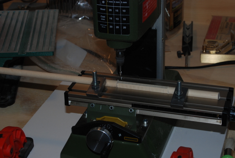
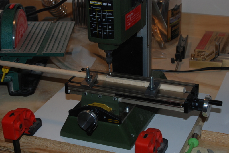
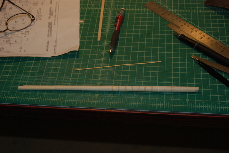
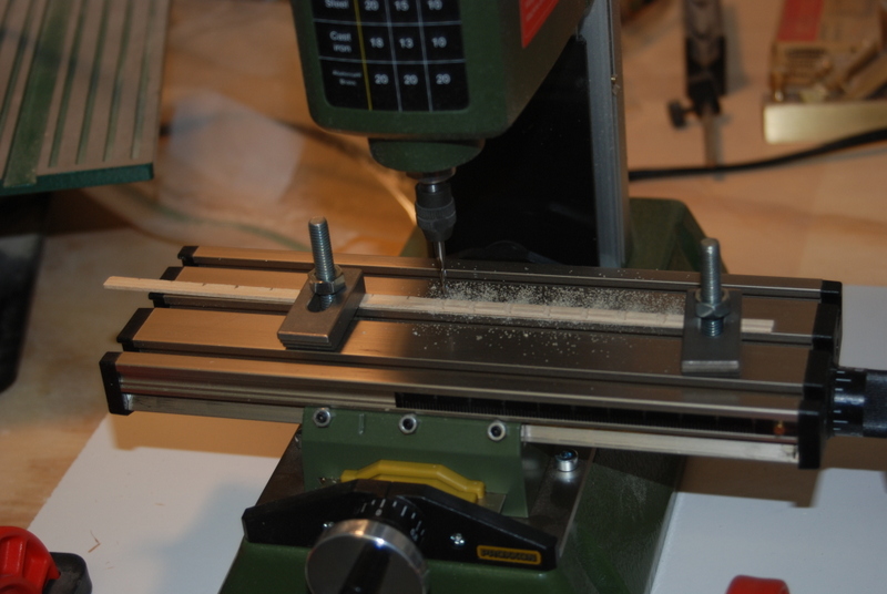
I hope everyone who celebrates this time of year had a nice holiday. I know I did. In between gatherings with family and friends I have been working on the lower fore mast. I was able to use the dowel that was provided in the kit. I first marked off and milled the square section and tenon at the top. I am starting to get an appreciation for these types of clamps instead of a vise for these longer pieces. I also spent some time making sure everything was centered and square before milling, which for these longer pieces is very important, as small errors get magnified. I tapered the square section and fit the two pieces that make up the mast cap to the tenon. I then tapered the round section on the lathe and sanded in the transition from round to square. I cut strips of manila folder to make the 16 bands around the round section, after marking their positions on the mast. I put the joint in the front center of the mast, as this area will be covered by the chafing fish. I cut sections of basswood strips for the chafing fish, and rounded the backs of them with the Dremel ball grinding bit in the mill, and finishing them with some sandpaper on a piece of dowel. I also filed in the angles along the edges on the upper part of the fish, where it will join other pieces of the fish. I marked the locations of the bands, then milled slots in the back for them. I then glued the fish to the mast, using lots of clamps. Next I will add the other pieces of the fish and round the outside faces of them to be parallel to the mast.
- 1,354 replies
-
- 6
-
-
- constitution
- model shipways
- (and 1 more)
-
Thanks Popeye, Steve, and Al, and for the likes. Popeye - I started this new job in Feb. and they shut down next week, so everyone gets it off. I wish more companies did that. Steve - Thanks. Have a great holiday too. Al - It is all new to me but it has been fun playing around with it. My father was a machinist, and my brother-in-law and my nephew are both machinists too. I got nothing on them and they laugh at the size of my machines. But, I have help if I need it. I gave the steps a coat of white paint and just glued them in place. Once they dry I will clean them up a bit more and give them a second coat of paint.
- 1,354 replies
-
- 4
-
-
- constitution
- model shipways
- (and 1 more)
-
Dave,I am pumped to follow along with your build. I can't wait to see the details you can add at that scale. And I am very happy to be of help as you proceed. Of course, I am two years into my build so some of the procedures I used in the beginning are slipping into the fog...
- 742 replies
-
- 7
-
-
- constitution
- frigate
- (and 1 more)
-
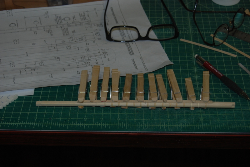
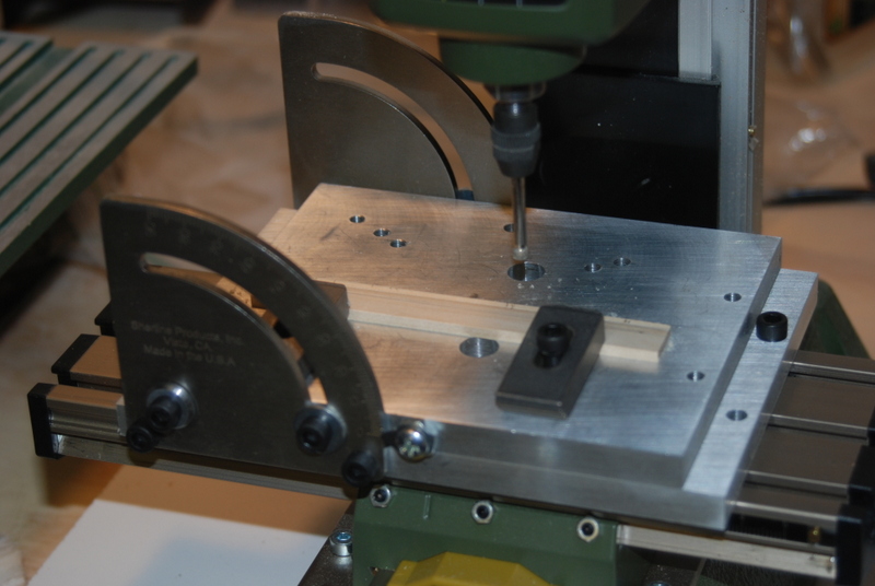
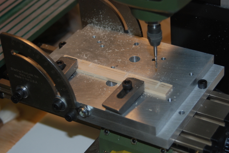
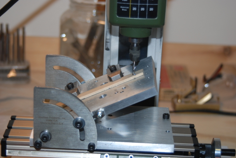
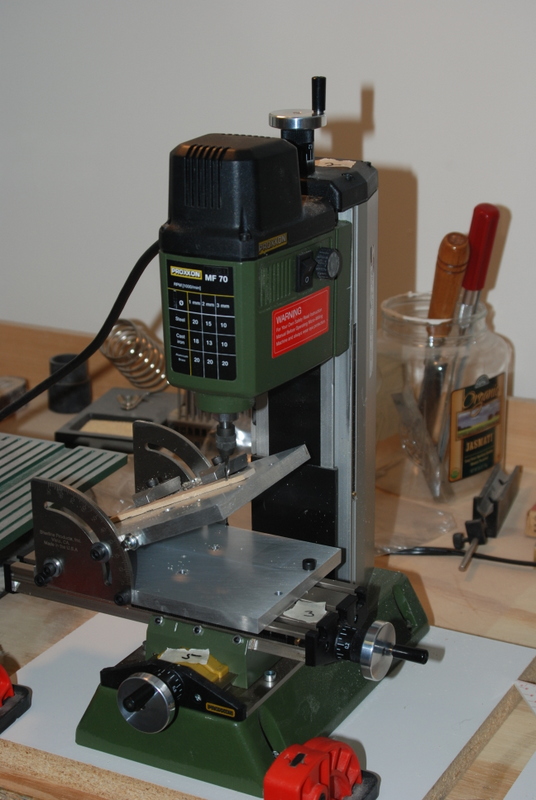
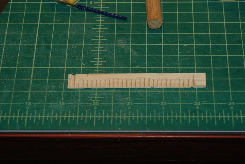
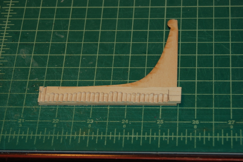
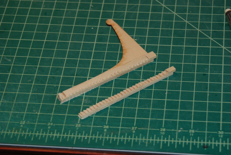
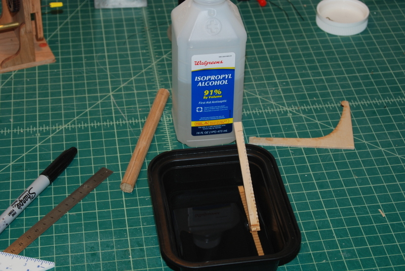
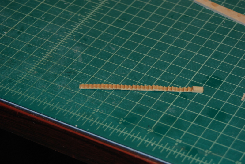
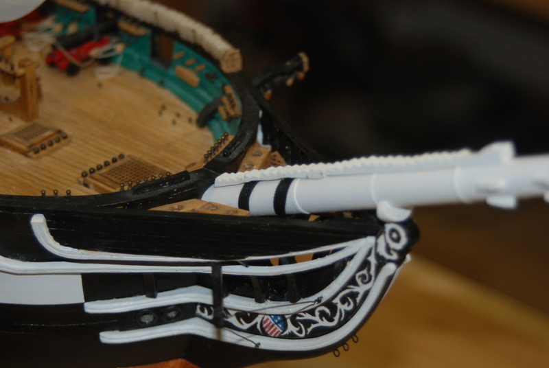
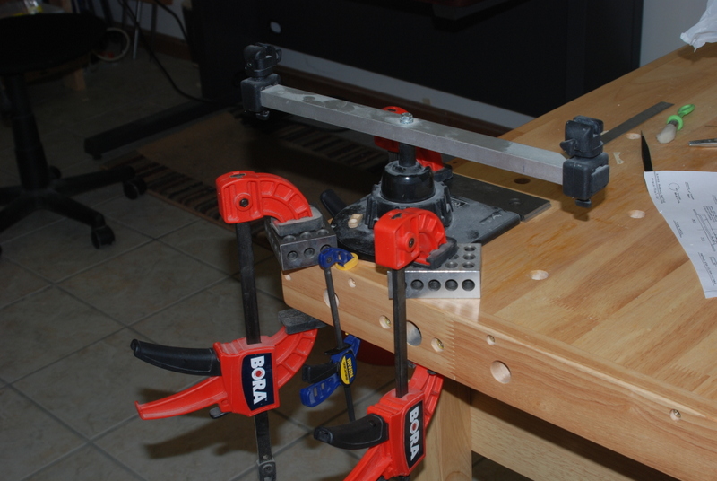
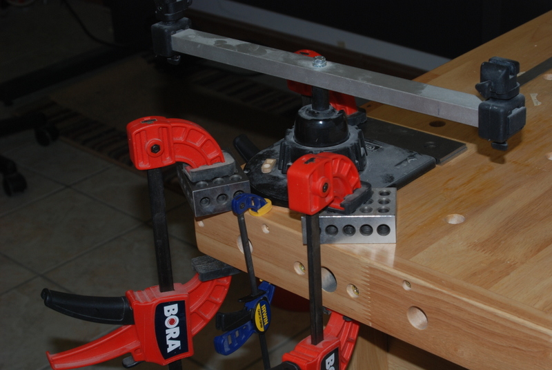
Thanks guys for the likes. I made up a new set of steps for the bow sprit last night and I took some pictures during the process. I made these while the old steps were still on the model, in case I couldn't do any better. But, luckily that was not the case. I did spend some time thinking this through before I started milling wood, which I think really helped. So, here we go. Bow Sprit Steps Take 2 After making the steps the first time, I realized that the right way to do this would be with a tilting table. So, since Proxxon doesn't make one for their mill, I bought the Sherline table and have adopted it to fit. Actually, I didn't really do anything to the table yet, as I can use just two hold down screws into one slot on the XY table. In the future, I should put a couple more holes in the base so I can use more then one slot, but for this job it was OK as is. I will be making some hold down clamps for the Proxxon vise to fit on the tilting table, but for this job the vise was not needed. The steps are 3/16" wide and at first I thought I would use a 3/32" wide strip (which I didn't have). I pulled out a 1/2" wide strip and realized I could use the edge for the hold down clamps and would have access to the whole area I needed to cut. The mill came with the hold down clamps, so I only needed a few extra cap screws to fit into the tilting table to use them, which I had. I first mounted the piece upside down, and with the table flat I milled in a slight curve to fit the bow sprit roundness with a dremel ball head grinding bit. I used a large round file and some sandpaper on a piece of dowel to finish this curve. I then marked the locations of the gammoning ropes and the bands on the bow sprit, and milled slots for these. Since I had extra room between the inner edge of the steps and the clamps, i could mill further than the line to get the sides of the slots straight all the way across the back of the steps. I then test fit the wood strip and was happy with the fit, so I mounted it right side up, checked everything for straightness, set the table to 26 degrees, and started milling the steps. I started at the top so I had much less chance of hitting the table with the bit, as I was going down hill during the cutting. You will notice the pieces of masking tape at each hand wheel to remind myself how many turns to make with each cut. i was surprised making them the first time how easy it was to get messed up. This time it went rather smoothly and before I knew it I was at at the bottom step. I removed the cut piece from the table and was unsure how fragile it might be. At this stage having the excess on the side was great as it added a lot of stability to the piece. Before I sliced the steps off from the blank, I tack glued it to a backing piece of wood, that I had squared up in the table saw. I didn't want the steps to come apart in the saw while slicing them off. After a few minutes, it was a simple process to slice off the steps to width. I then soaked the steps in alcohol until I could slide the two pieces apart with almost no pressure. Here was the moment of truth. I half expected the steps to fall apart in my hands, but they were very stable and sturdy, to my surprise. And this was all with basswood. My thought was to try it and if it was too fragile, use boxwood for the next set. After the alcohol had dried off, I painted the sides around the gammoning slots. Once I glue this down, I can then paint the rest of it without getting white paint on the gammoning lines. At this point I removed the old steps, which came off rather easily with a little twisting pressure from the side. Here are the new steps just resting in place, waiting to be installed and painted, which I will do tonight. I was very happy not to have to redo the gammoning lines for a third time. My Christmas vacation starts tomorrow, and I have all next week off, so I am looking forward to making some good progress on the rest of the masts.
- 1,354 replies
-
- 8
-
-
- constitution
- model shipways
- (and 1 more)
-
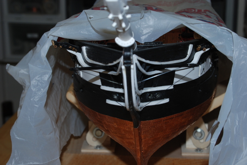
Bow sprit gammoning take 2. I made two new ropes last night for the two new gammoning lines. I have to say that making rope in the .02" to .03" diameter range is coming out really nice. I seem to have the process very repeatable with good results. I am using the Dormanoff rope walk in the horizontal configuration as I show in post #505. I am also using the back end from the ME rope walk, although I modified it by threading a bolt with the head cut off into the tube, which I can use with a hand drill to make the rope turns very quickly. The big break through came when I realized if I keep a lot more tension on the back end during the first winding, so that no hockles can form, then clamp the back end while I make the turns for the rope, and keep turning until the rope is nice and tight, this set up works well. I even have much less unwinding of the rope since I hold it under tension for a few minutes before taking one end off. While I was writing this I just got the .04 and .05 " diameter rope from Syren. It is beautiful and I am very happy that I am not trying to make rope this thick. To do it right, you have to make smaller strands then turn those into the bigger rope, which takes a lot of time. To do the gammoning this time, I put one loop around the bow sprit and held the rope vertically, then drilled a hole at that location for a piece of wire to act as a stop while I did the rest of the turnings. After I wrapped the second gammoning and tied them both off, I coated the turns with some diluted white glue to hold them in place while I marked their locations on the steps and filed away a groove in the steps to fit over them. I removed the wires and glued the steps on. Well, let's just say this step didn't go too well, as I broke the steps so now I had three pieces to line up. Here they are glued onto the bow sprit. I am not happy with these, although I probably could live with them. But, since I seem to do all of the hard stuff three times, I am going to attempt to make a new set of stairs, but leave these on until then. I recently bought the Sherline tilting table which I am adapting to the Proxxon mill, so I should be able to make the stairs in one piece. i also want to make them thinner and more even, and I think I have a way to do that. I'll take pictures of the process and post them here as I go.
- 1,354 replies
-
- 7
-
-
- constitution
- model shipways
- (and 1 more)
-
Thanks Dave. There are some great Constitution build logs on MSW that I have used a lot, including the current build by XKen. I can't wait to see your approach to this ship. I finished the collars for the bow sprit using three different sizes of served line. It got easier working with the served line as I went along. The lashing lines are on so they are all ready to install on the bow sprit. But before I do that, I want to install the gammoning. Since I am building an 1812-ish version of the ship, I am using rope gammoning instead of chains, as on the modern version. I had made the holes for these in the stem very early in the build, and I have pretty good access to this area under the bow gratings. I made two gammoning lines with the rope walk and installed them last night. I was not happy with them, though, because there are no stops on the bow sprit to keep them from sliding down toward the bow. The steps that go over the gammon have cut outs that act as stops, but I am going to install them after the gammoning is on. The forward line was really bent toward the bow. Anyway, I removed what I did and after making more rope, I will try installing them with temporary pins installed to act as stops until I get the steps put on. These have since been removed. they look good from the top, but if you looked inside you would see they are bent. The gammoning should be straight up and down when seen from the side, according to the TFFM Vol 4 Rigging book, which I am finding very valuable for general rigging information.
- 1,354 replies
-
- 8
-
-
- constitution
- model shipways
- (and 1 more)
-
Yes Bill, it is good to treat them as little projects. I built the Bounty Launch a few years ago and I found it was a good starter for both hull planking and fitting out these boats, although at a much bigger scale. I got the new power supply for the rope walk so that is back in business. I thought I was going to have to swap out the plug from the old one to the new, but it turned out the new one had the same plug, so I just plugged it in. I spent several hours last night trying to make rope large enough for the shrouds and stays, but with no real success. I have just placed my order with Chuck for .04 and .05 diameter ropes for them. I know, I should have kept trying but there is enough rope at .035 and below to make that will keep the rope maker humming. That I can do. Also, bad rope at those big sizes is just so obvious I don't want to compromise the model with it. I made the three bobstay collars but don't have pictures of them. I used the served rope I showed earlier. I have never worked with served line before and I found I have to treat it differently from non served line, especially when doing a seizing. I am used to making a seizing, tightening it up but not all the way, sliding it into place, then doing a final tightening. With served line, it doesn't slide, and if I force it, the seizing gets bunched up and shows the line underneath. It took me a few tries to figure out how to deal wit this, but I was able to make the seizing near where it needs to be, position it, while very loose, and then tighten it up. It seems like the seizing stays tight better on served rope than non-served rope for some reason, so that is a good thing. I also found that the collars are all different sizes, so I couldn't go off the plans, but had to test fit each one as I assembled them. Have a great weekend all.
- 1,354 replies
-
- 4
-
-
- constitution
- model shipways
- (and 1 more)
-
Not true Steve. I find making good crisp joints at small scales is one of the harder things to do. Yours look great.
- 108 replies
-
- 4
-
-
- mamoli
- constitution
- (and 2 more)
-
Hi popeye. I am looking forward to following along. Be careful with that .5mm planking. Not much wood there to sand after planking. I'd be through it in a few swipes before I knew it.
- 453 replies
-
- 5
-
-
- thermopylae
- sergal
- (and 1 more)
-
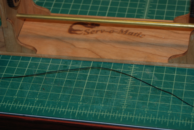
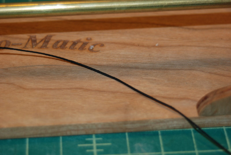
Thanks Steve, Steve, Ken, and Popeye. It feels good to hit a major milestone but at the same time it makes me think of all the work still to come. Probably another year or so, which is fine as I love rigging, and this ship has a lot of it, for sure. I got ready to make some rope for the bow sprit collars and gammoning. I put the 4 lines on the rope making machine and hit the switch - nothing! I had left the power supply plugged in since the last time I used it and it seems to have given up the ghost. So, I have ordered a 9v power supply from Amazon which should be in tomorrow. In the mean time, I spent some quality time with the Serv-O-Matic last night. Since the collars are served their whole length, I could use line that I already have as the core, since it won't be seen. I served up about 2 feet which took a while, as this is the first time I have used the serving machine. I was having problems keeping the serving from wrapping over itself, but I found that I could unwind it a few turns and get back on track. There were a few times that I was able to get in the groove and serve a few inches without back tracking. I was pleased with how this came out, but I am going to have to get better before I serve a whole shroud. I'll have lots of practice with this build, though. I will be using sections of this line for the different collars, so I can work around the areas that are not perfect. This is .028" line as the core with thread that I use for seizing as the serving line. The resultant served line is .038" diameter.
- 1,354 replies
-
- 4
-
-
- constitution
- model shipways
- (and 1 more)
-
A great start Ken. I look forward to following along. You have gotten off to a fast start.
- 162 replies
-
- 4
-
-
- dirty dozen
- fishing
- (and 2 more)
-
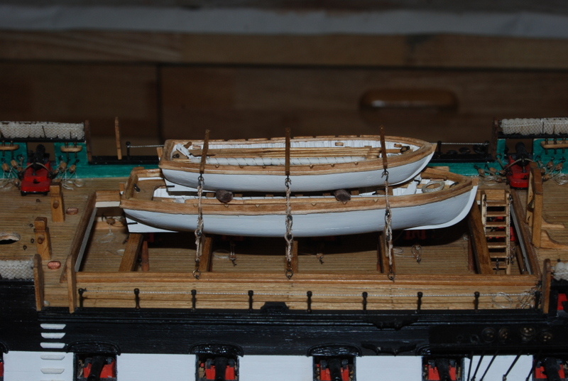
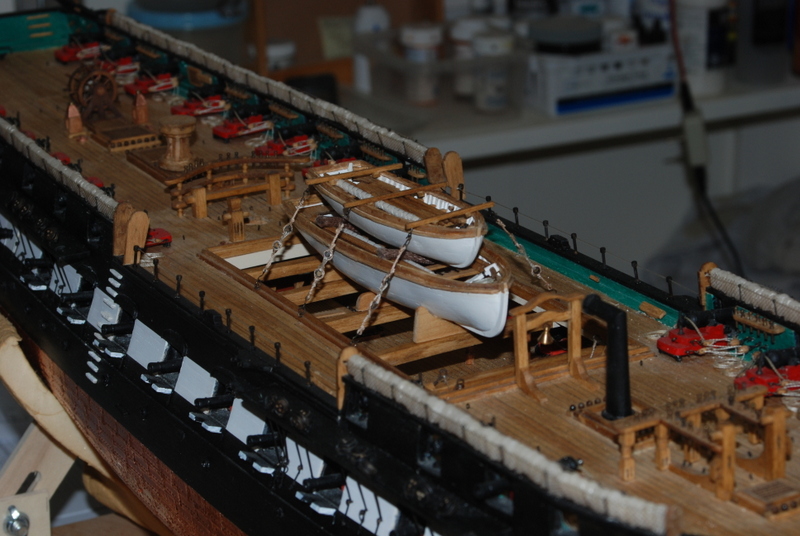
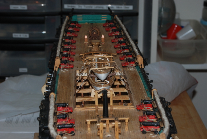
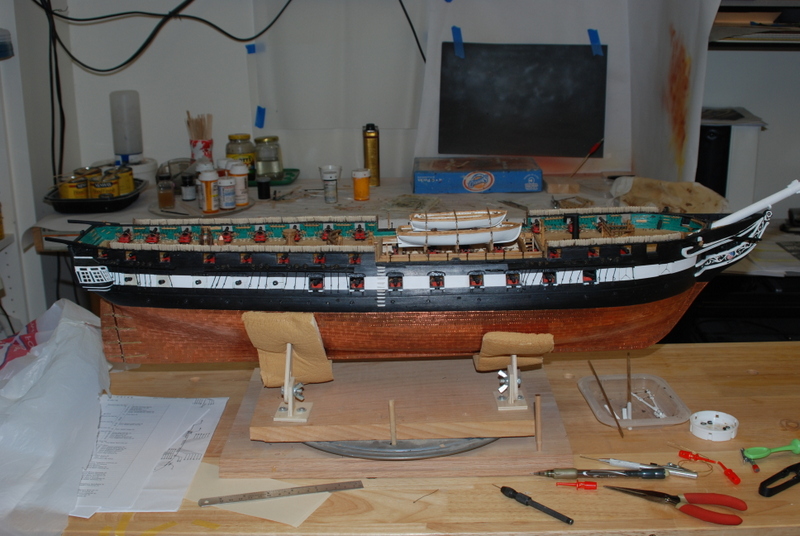
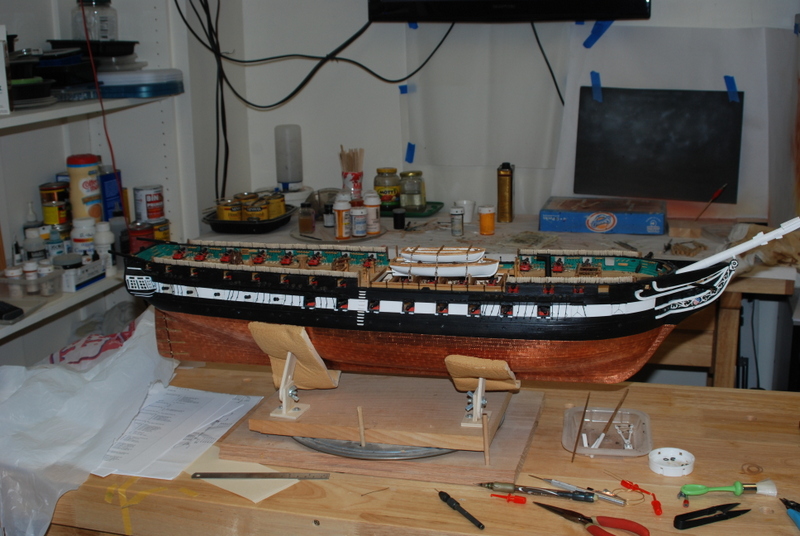
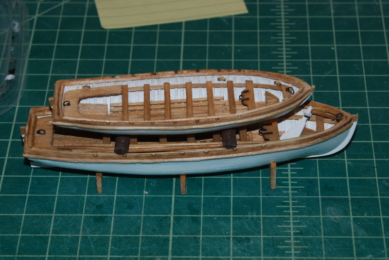
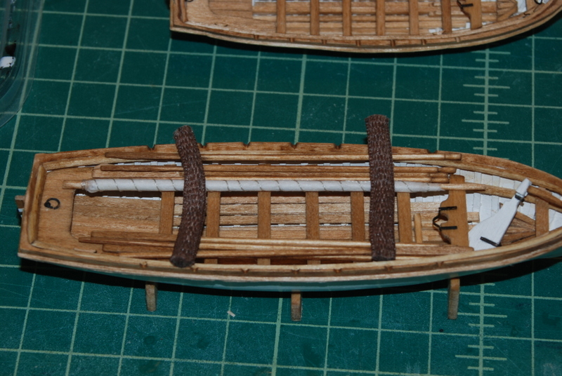
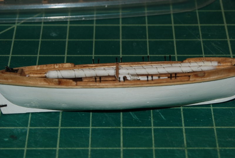
Thanks Ken. I hope you can use some of this when you get there. I have certainly used your expertise in the parts you have done first. Thanks Popeye. And here are the two cutters lashed down to the open waist beams. (The gig I have put away to add to the stern davits after all the rigging). I made cradles for the large cutter, which I pinned to the fore and aft waist rails so the boats would not move after being lashed down. I made the tie downs in two pieces with aluminum thimbles in the middle. I was going to use brass but found the aluminum easier to cut. I did not try heating the brass first, but I will the next time I need to cut brass. I was surprised that the Casey blackening solution worked on aluminum really well. I remade these ties a couple of times until I was satisfied with the seizing around the thimbles. I was also happy to see that the boats did not completely block off views into the waist, so not all that work down there is hidden. So, after nearly two years, I have come to a major milestone. All of the hull and deck work is done and I can now start the mast making and rigging. As you can see I have already started the mast making with the bow sprit, but now I can focus on that aspect of the build. I have always made the whole mast first then mounted it on the model, but I happen to be reading the TFFM Vol IV Rigging book and I like how Mr. Antscherl does each mast in sections. I am not fully decided on this yet. Here is the ship as it looks now, ready for the masts. Have a great weekend all.
- 1,354 replies
-
- 10
-
-
- constitution
- model shipways
- (and 1 more)
-
Miniature Hand Tools
usedtosail replied to Julie Mo's topic in Modeling tools and Workshop Equipment
I have these small chisels but have used them only a few times. For what I needed them for, they worked well. I also have the small plane which I love and use all the time.- 100 replies
-
- 10
-
-
Wow, that is a beautiful model, Dave. Great job!
- 962 replies
-
- 6
-
-
- sovereign of the seas
- ship of the line
- (and 1 more)
-
Ken, I use this AOS book with a big grain of salt. There seems to be quite a mix of time periods represented in the plans, from what I can tell. That said, if I have no other information I will use it as a reference. For instance, I plan to make sky sail masts above the topgallant masts, as shown in the book, because I have seen these referenced in other sources. The small boat information was also very good. Other AOS books, like the one for the Beagle, was really valuable to me because of a lack of other references.
-
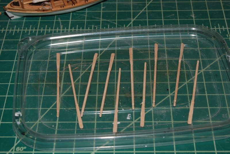
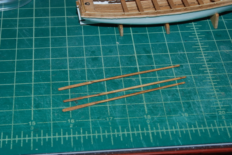
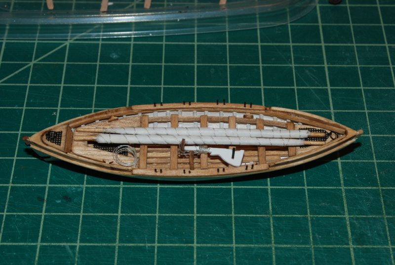
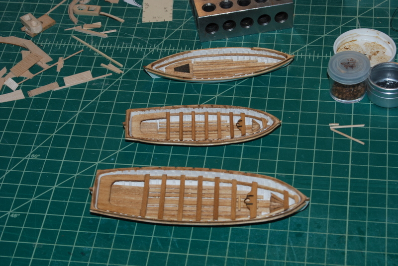
Thanks all for the kind words. It is so nice to be a part of this MSW community. I have had lots of time to work on the Constitution, which is always very therapeutic. I am focused on finishing up the small boats so that I can get on with the mast making. I had to bend some wood strips for the railing on the gig that goes between the splash rails. I edge bent them using the base of the keel clamp I have, which had just about the exact radius I needed. I used a bunch of clamps and blocks to get them to lay down flat. After they dried, I cut out the sections I needed and glued them down with very little pressure needed. Here is how they came out. As an aside project, I woke up one morning with the notion to replace the wire bumpkin supports I had, since they were not very straight. I had recently read Ken's (xken) build log where he stretched the wire between two pliers to straighten and harden it. I had tried this when I first made the supports but was not successful, so I tried it again and it worked great. I thought I was going to have to remove the eye bolts and replace them that way, but they were really in tight, so I was able to open up the loops on the ends of the wires, take the old wires off, use them as templates to get the lengths of the new wires, place the new wire into the eye bolts with the loops still open, then close them when they were installed. Here are the new ones. I am much happier with these. I have been doing some thinking about how to stack the two cutters on the waist rails. The plans show only the large cutter with cradles underneath and strong backs over the tops to hold it down. I could either use the same method and use cradles on the small cutter to sit on the strong backs, but I thought they might stick up too high. In the AOS book, they show the small cutter inside the large cutter, with fenders between them. I liked this method better, but was struggling how to make fenders until one day, as I was tying my shoes, it hit me to try pieces of shoe laces. I bought some white oval laces and after cutting the pieces, I browned them using brown shoe polish. I was quite happy with the look: I had first tried this with round laces, but it didn't look as good. I have been making the accessories to go into the boats, which in my case include masts with furled silkspan sails, wrapped with line, oars, rudders with tillers, and rope coils. The rudder for the gig also has a yoke with line attached, which I wrapped around the rudder for storage. I made the oars in two pieces, a shaft and a blade. I used square wood for the shafts, first making a slot in the end for the blade, then sanding it into an octagon shape, then rounding it in the lathe. I also shaped the handle while it was in the lathe. I then made the blades, glued them into the slots, then cleaned up the joint with a small file and sandpaper. I then stained the oars with oak stain. Here are some oars just after gluing them together: And here are some finished oars: One last little detail. The thole pins on the gig are very small. I used wire for these but just didn't like the unfinished look of the tops. So, taking a clue from Nenad's Cutty Sark build, I placed a tiny bit of CA on the ends of the wires, then painted over the CA with thick black paint. Now the thole pins have a bit of shape and to me look better. Hopefully I will be able to wrap up these small boats this weekend. Thanks for watching.
- 1,354 replies
-
- 9
-
-
- constitution
- model shipways
- (and 1 more)
-
Looks great Mike.
-
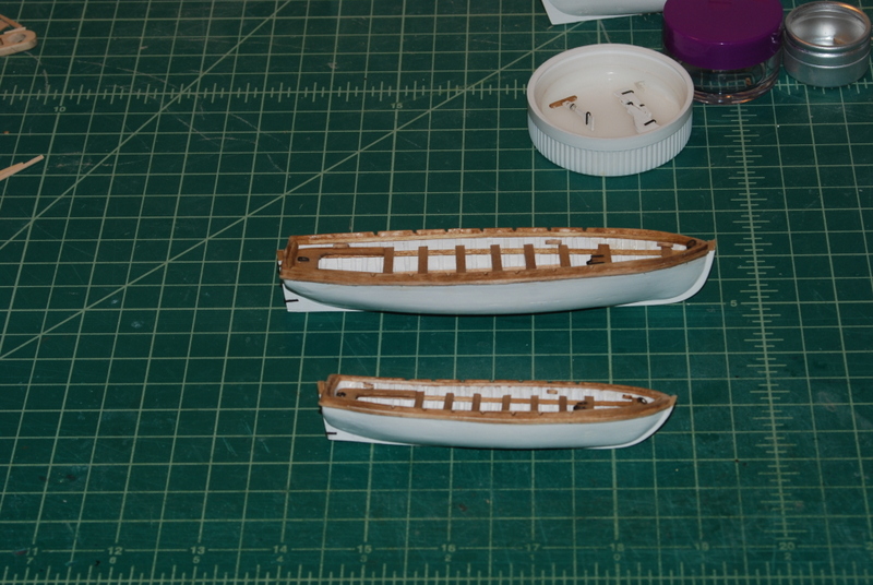
Thank you Geoff, Al, and Denis, and those who hit the like button. I realize that the dust cover will work for now, but once I put the masts up I'll have to improvise something else. I hope all our US members had a great Thanksgiving. It was hard for us this year as my father passed away last week. He would have been 94 next month. He went peacefully and we are sad but at the same time a bit relieved that he did not have any serious illnesses that would have caused him to suffer. I will now devote the rest of this build to him and my brother who died a few years ago. Rest in peace, George. I finished the two cutters this morning, by adding the cleats, lifting rings, and the gudgeons. The rudders are finished too. I still need to make the masts and oars to go inside them. For the mast fitting hardware and the pintels and gudgeons, I used left over blackened chain plates. They are nice thin brass that I was able to bend around the stern posts and rudders easily. I am still working on the gig but it should be finished in a few days. Then I will be able to focus on building the masts.
- 1,354 replies
-
- 7
-
-
- constitution
- model shipways
- (and 1 more)
-
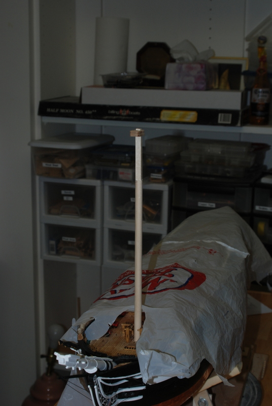
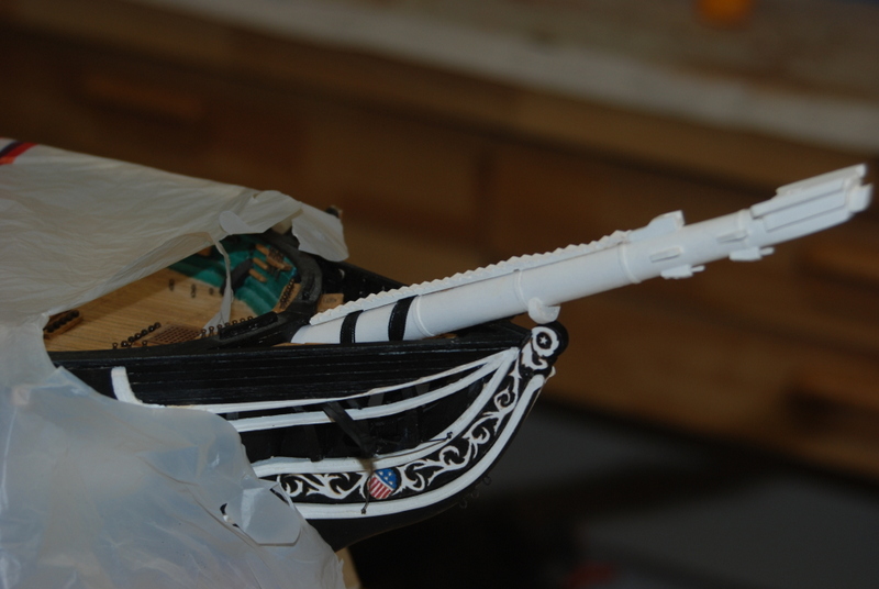
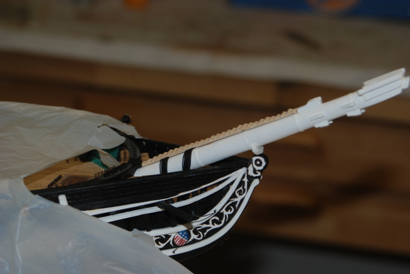
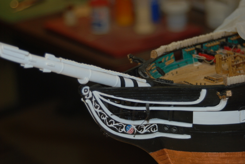
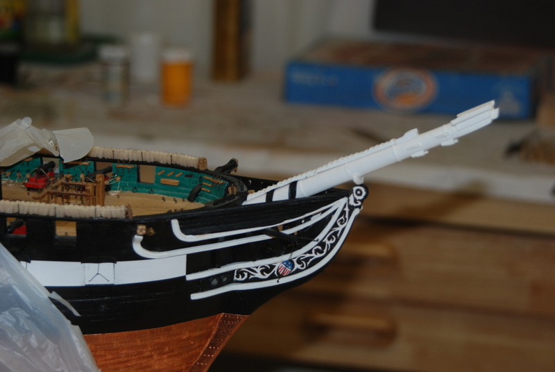
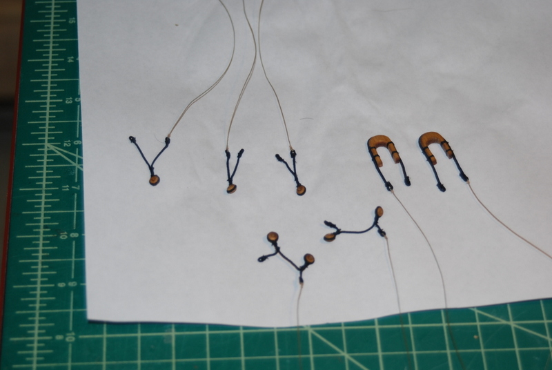
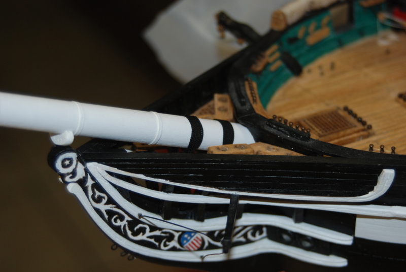
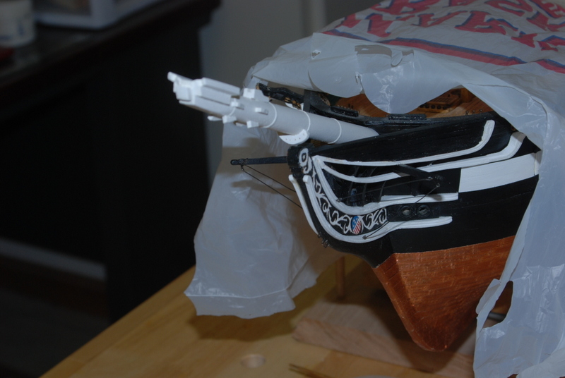
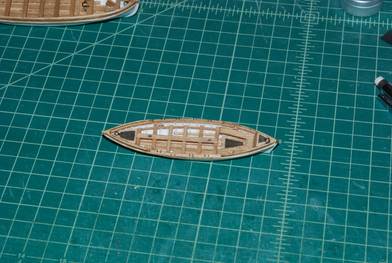
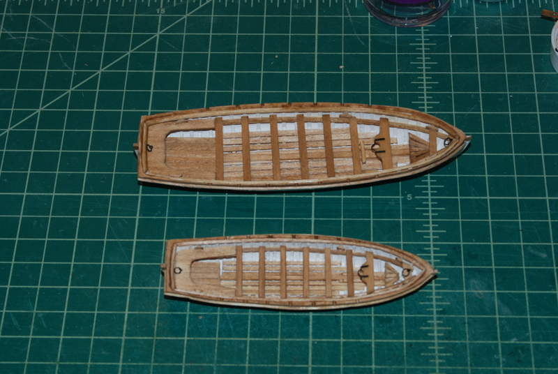
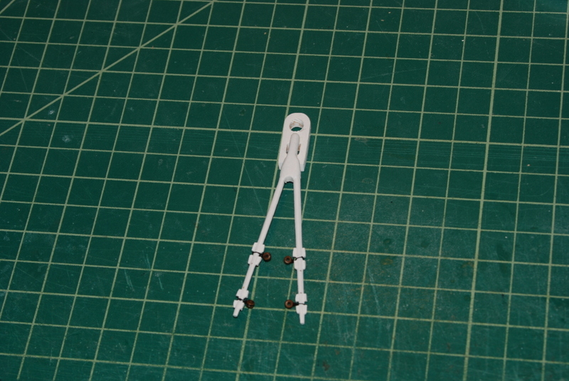
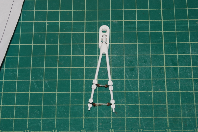
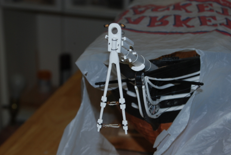
Some progress to show. I continue to fill out the details in the ships boats. Here I have added the floors, benches and thwarts to the two cutters, and the floors and foot rest to the gig. I am working on the thwarts and stanchions for the gig, and the gunwales for the cutters. I should have pictures of those soon. I also was working on the martingale for the bow sprit. I added the bulls eyes by seizing them to some line, wrapping the line around the leg of the martingale, tying an overhand knot, and holding it with some thin CA. I then added the lanyards by seizing a piece of line through one bulls eye, wrapping the lanyard three times through the bulls eyes, then seizing the end around the wrapped line to hold it. I added the blocks and eye bolts and other hardware to the cap and here is how it looks on the bow sprit. How do you like my high tech dust cover for the hull? It is just an opened up grocery bag, but it actually works pretty well. It is very light and comes on and off easily, so I don't worry about damaging anything when I put it on.
- 1,354 replies
-
- 10
-
-
- constitution
- model shipways
- (and 1 more)
-
Very nice. And can you show how you made them, please.
- 1,051 replies
-
- 2
-
-
- cheerful
- Syren Ship Model Company
- (and 1 more)