usedtosail
-
Posts
2,421 -
Joined
-
Last visited
Content Type
Profiles
Forums
Gallery
Events
Everything posted by usedtosail
-
 OK, I found the file that shows the curved fife rail. It is file 49805001_1.pdf on the set of files that I have. If that is not on the CD, I can send you the pdf file in a PM.
- 1,354 replies
-
- 1
-

-
- constitution
- model shipways
- (and 1 more)
-
Bill, you are correct as there seems to be different versions of the CD. I actually downloaded the files from the web site before they were taken down, so I don't really know what is on the CD or what versions are out there. I also renamed all the files to make them easier for me to find stuff. I will go back and find the file that shows the curved fife rail and you can see if you have it. From now on I will stop referring to the files I have as from the CD, because my assumption that the files I have were all on the CD looks to be incorrect.
- 1,354 replies
-
- 1
-
-
- constitution
- model shipways
- (and 1 more)
-
Sorry, JS, that pdf is on the Constitution CD. The files on the CD used to be available from the web site, but the Navy took them down. Send me a PM with your email and I'll send it to you. I could not find an image of the full picture, but that piece came from the pdf document.
- 1,354 replies
-
- 1
-
-
- constitution
- model shipways
- (and 1 more)
-
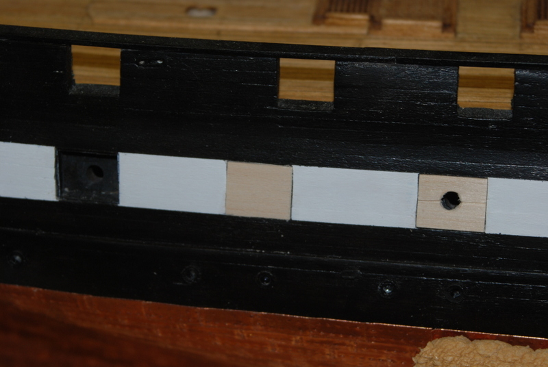
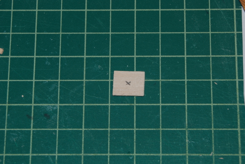
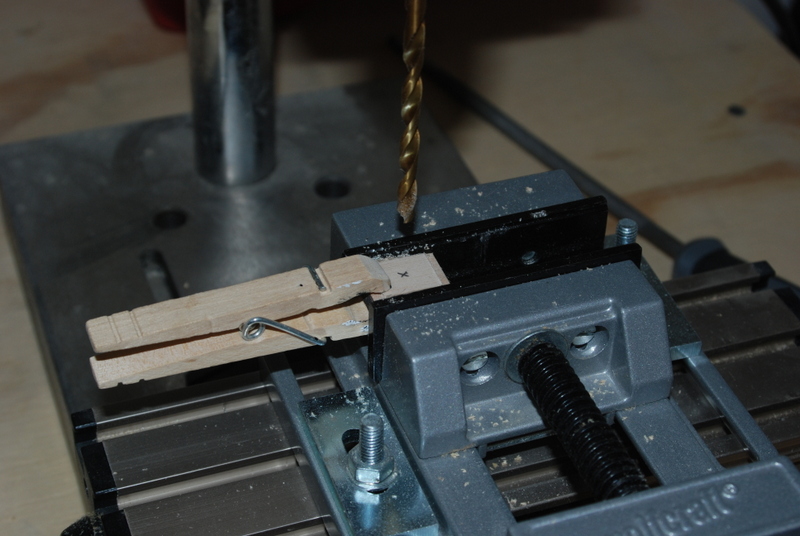
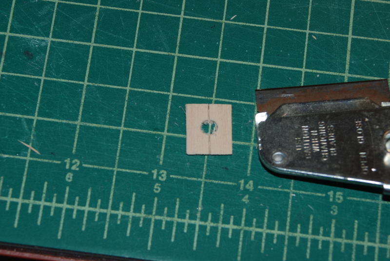
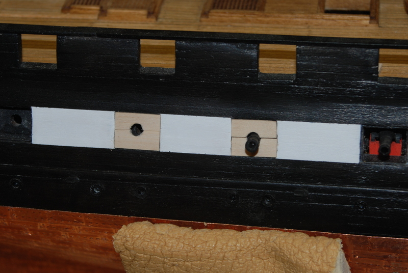
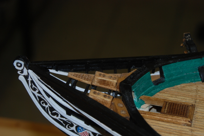
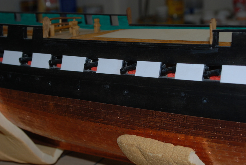
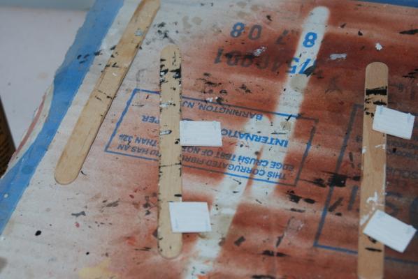
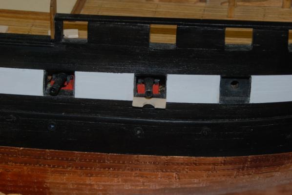
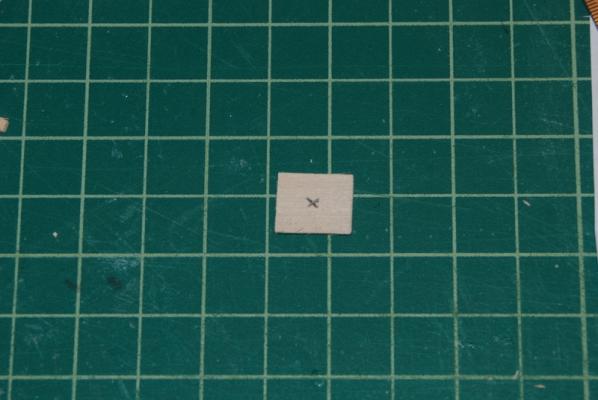
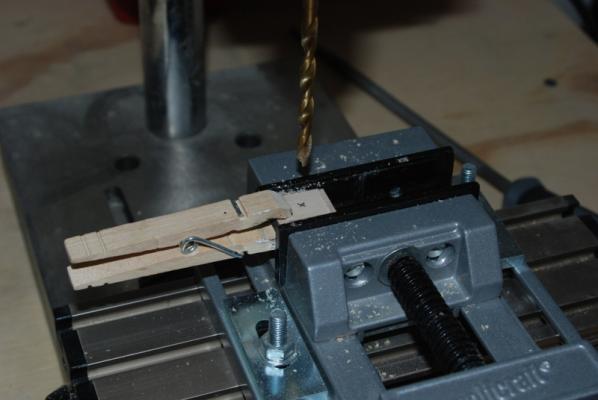
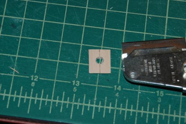
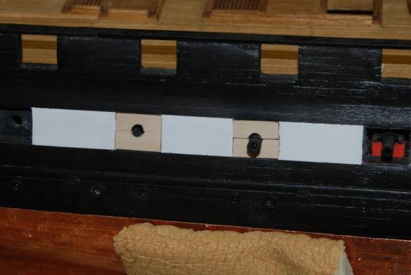
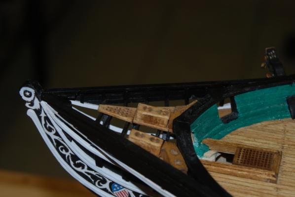
As promised, here is the progress on the gun port lids. I started with the four full size lids for the front two ports on each side. I first had to thin down some sheet stock to the 3/64" width from 1/16". I used the Byrnes thickness sander for the first time and it worked great for this. I cut out pieces to fit snugly in each gun port, then used the back of an X-Acto blade to score plank lines into them to match the hull planking. I drilled holes in the bottom for the pull lines and glued etched hinges to the front. I am in the process of painting these white. For the half lids under the full cannon ports, I cut a strip of the thinned sheet that was the height of the half lid, then cut individual pieces from this for each gun port (starboard side only for now). I stacked these together and clamped them in my vise, then used a round file to make the round notches in them, all at the same time. I sanded these for the final fit. The only problem with this picture is that I have the lid inside the recess around the gun port. I think that these would really hinge so that they were below the recess when open, otherwise there would be nothing to stop them from opening all the way. This means I need to have some sort of physical support for these, like pins into the hull, but they are very thin so drilling holes for pins could be a problem. I think I might be able to make static hinges for these that will act like shelf supports and hold them in place, providing some support for them. I need to do some experimentation for these. For the closed half lids which will be around the dummy cannon barrels, I first thought I could use two half lids, but they did not meet up well in the center. So, I started with a single piece that fit into the gun port opening, like the full size lids. Once I had a good fit, I marked the center by connecting diagonal lines from the corners, then used the drill press to drill out a hole that the canon barrel will fit through. I then used the razor knife (with apparently a very rusty blade!) to split that piece in half, cutting with the grain of the wood to get a nice even line. I then fit both pieces in place, and they are ready for the hinges to be added. Lots of work left to do on these but a I am happy with the start I have made.

- 1,354 replies
-
- 7
-
-
- constitution
- model shipways
- (and 1 more)
-
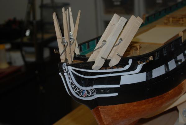
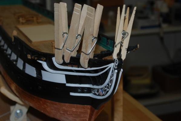
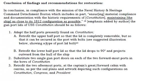
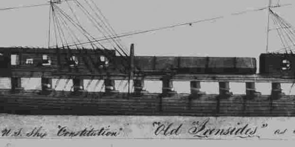
Thank you George. I hope this build will be as useful to future Conny builders as those logs that I have been using are to me. Thanks for the likes too. It is exactly 2 years since I started this log, and I probably have another year to go at least. With my current job situation I will either end up with a lot more time for modeling or I may be starting a new job right away, which will cut into the modeling time I have now. Financially I am hoping for the latter but deep inside I would rather spend more time modeling. I can't tell the Admiral that though. I am still working the planks along the head area. I was able to add a few to each side, but now I have to do each one separately since I have to have the previous one glued in to fit the next one. I started at the top rail and am working my way down to the middle rail. I did paint the rest of the plank supports inside the planks after I glued in the first batch, so now it is just getting those last planks cut, fit, painted and glued in. In between planks, I have started making the gun port lids for the gun deck guns. I am going with the latest developments from the Constitution research team on how they think the gun port lids looked in the past. Here is the conclusions I am building too (mostly). From Gun Port Lids/Half Ports, a pdf on the Constitution web site, Researched and written by M.M. Desy, Historian Naval History & Heritage Command Detachment Boston February, 2013: Here is the painting they used to justify the 90 degree lower lids: The first two gun ports have dummy cannon barrels in them on my model, so I am going to just make full size port lids and have them closed, with hinges on the top and lines to open them going into the hull above them. No dummy barrels will be needed in those ports. For the next gun ports that have full cannons in them, I am making half lids for the bottoms, which I will show open at 90 degrees from the hull. They will have hinges on the bottoms, but no lines to open them, as the crew could just reach out to open and close them. I will not show any of the upper lids, as these would be stowed inside with the guns run out. All the remaining gun ports, which are to the rear of the ones with full cannons, have dummy cannon barrels in them. I will make both upper and lower port lids for these and show them with the dummy barrels sticking out through the hole. I will show hinges on only the bottom half, as the top half would not have them. I am not going to try to make canvas looking fillers in the last two gun ports, though, although I may change my mind on that point. I am not sure how I could make them look realistic, so I am going to make closed ports for now but try my hand at making canvas covers before using them. More on how I am making these lids in the next post. Finally, I want to wish you all a belated Happy New Year. For me, this is going to be an interesting year.

- 1,354 replies
-
- 8
-
-
- constitution
- model shipways
- (and 1 more)
-
Ken, try this site: https://www.google.com/maps/@42.3724827,-71.0566781,3a,75y,318.43h,79.36t/data=!3m7!1e1!3m5!1sAsptIcubDkcAAAQZN_oM_Q!2e0!3e2!7i13312!8i6656 You can literally walk around inside the ship and get many different views of the recent interior.
-
Looks great Bob. All those lines at the bottom of the sail do look challenging!
- 196 replies
-
- 4
-
-
- higaki kaisen
- woody joe
- (and 1 more)
-
Congratulations Tom on a beautiful model. The only cure is to fire up another one at this point.
- 212 replies
-
- 1
-
-
- constellation
- artesania latina
- (and 2 more)
-
Thanks Tim. Despite your current setback with the Essex I am really enjoying following your progress.
- 1,354 replies
-
- 2
-
-
- constitution
- model shipways
- (and 1 more)
-
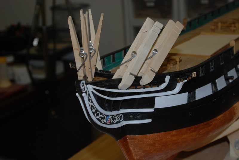
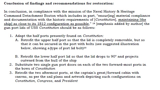
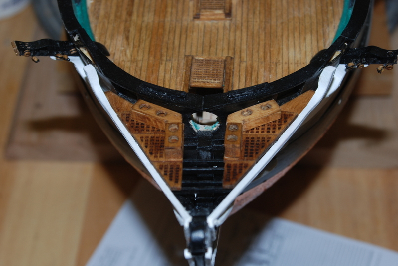
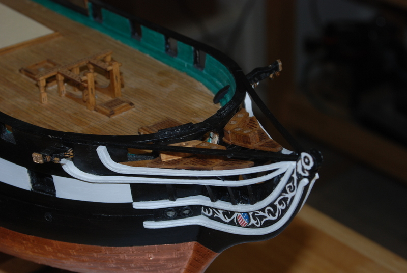
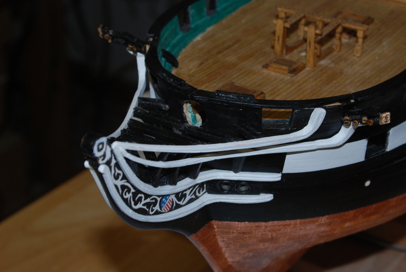
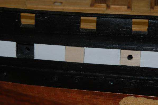
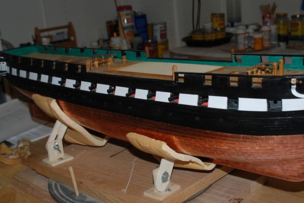
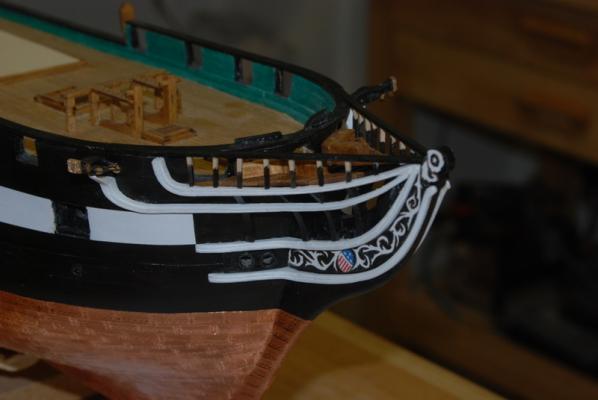
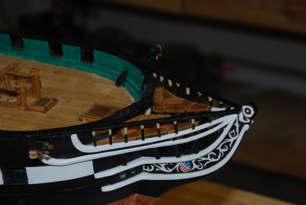
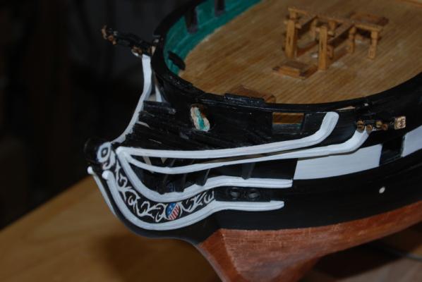
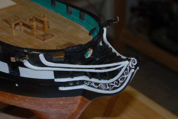
Both kids were home for the holidays but I did have a little time in the shop too. I cleaned up the head gratings and made the seats of ease. I finished these in oak stain and glued them in place, along with the solid pieces that flank the openings to the head. I made the two top rail pieces, painted them black and glued them to the openings left in the bow rail. While waiting for the paint to dry, I finally filled the holes in the sides of the hull. I drilled out the holes for the air ports and scuppers and glued them in place, then touched up the black paint on them. I made the supports for the planking between the top rail and the middle rail. I painted the bottom half of these black so I don't have to paint up to the white rail, and will paint the rest of them after I plank over them.


- 1,354 replies
-
- 12
-
-

-
- constitution
- model shipways
- (and 1 more)
-
There is still a lot of controversy on whether the Conny had 5 or 6 windows in 1812, which is the year I am building towards. I did exactly what George said to add 5 windows - moved the four transom pieces to fit between the window frames. I also did not add the spar deck chase ports as the notes I have said they weren't cut in until 1813. But it really comes down to what year your are going for and what other changes you want to make to conform to that configuration of the Conny. If you are building to today's configuration, I would keep the 3 windows as in the kit. If you are building to an older version you have to look at what other changes have been made since then.
-
Hi Ken. Nice job on those quarter galleries. I ended up remaking the windows closest to the hull from scratch so they would fit right, but yours look great. That is pretty ingenious to make them removable like that. As for the stern windows, I made mine 5 windows so that it was easier to use the kit supplied transom pieces. I think 6 would have been more historically accurate for 1812, especially since that is what the Hull model shows. I liked the 5 window configuration because the windows look square, whereas with 6 they would look thinner. Anyway you do them, I feel they will look great.
-
Oh yes, this is part of her history, and not a very good part to me.
- 1,354 replies
-
- 2
-
-
- constitution
- model shipways
- (and 1 more)
-
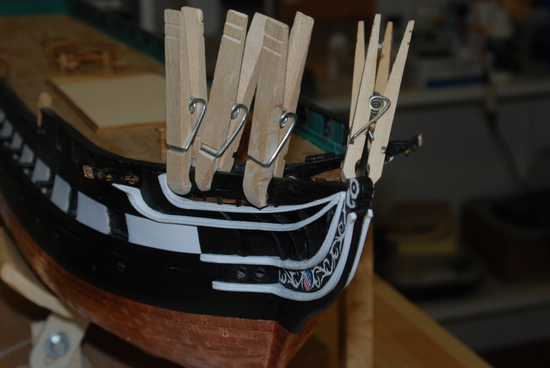
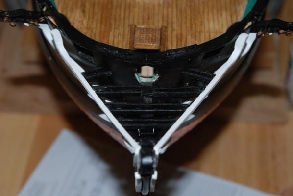
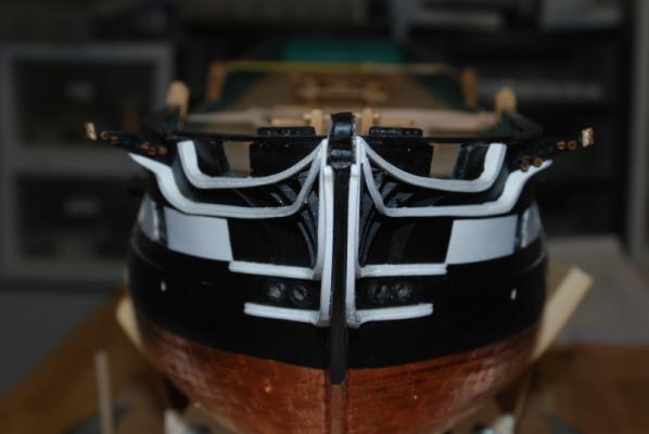
Here are the pictures of the main rail installed and the cross beams to hold the gratings. I was able to fix the white stripe on the port side by painting white above the stripe, then masking it off and repainting the black. Now the gaps on both sides are the same. I have the gratings all cleaned up and I am in the process of staining them. I also made the seats of ease and stained them too. After I install them, I will add the rest of the top rail and the knee at the front of the stem, then plank the area between the middle rail and top rail.
- 1,354 replies
-
- 9
-
-
- constitution
- model shipways
- (and 1 more)
-
Arthur, after suggesting to you to use thin CA, I thought I better give it a try myself. It worked great, and was easy to do. Just don't get any CA on the outsides of the plates as they will not age under those spots like the rest of the plates.
-
That gun looks great, Ken. You look good to go with them.
-
Have you seen this topic? http://modelshipworld.com/index.php/topic/12197-bolt-heads-on-brass-strips/?p=369370
-
Ken, because I used the planking to plank part of the gun deck, I ordered more to plank the spar deck. I think I just ordered one of ME's basswood strip packages. I ended up with almost just enough - I had to rip a couple of planks from wider stock to finish the spar deck. I would recommend making up one of the cannons to test the gun port height. I used the dimensions like you for the subsurface and the planking, but the guns were too high in the ports. My solution was to trim down the carriages along the sides.
-
Jay, nice job on the masts and figures. This is great work.
-
Sal, your attention to detail and your craftsmanship are top notch. This is beautiful work.
- 659 replies
-
- 4
-
-
- syren
- model shipways
- (and 1 more)
-
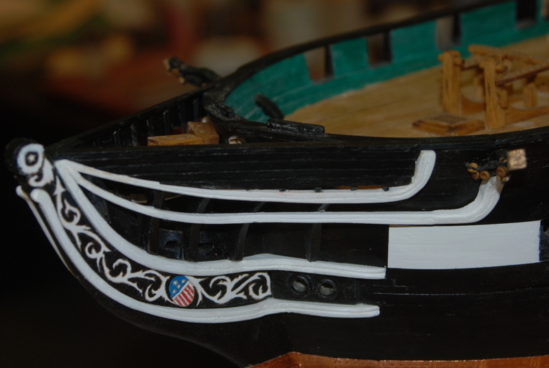
Thank you George, Greg, Jay, and Sal. And also the likes. Last night I added the main rails, but tonight I need to do some clean up of the paint around the rails. The main fix I need to make is that when I added the main rails, there is a very noticeable difference in the gap between the rail and the top of the white stripe on the port and starboard sides. In the last picture you can see that the white strip is actually thinner on the port side than the starboard side on the end, so I am going to attempt to correct that tonight with some white paint and masking tape. I will have pictures of how it turns out either way.
- 1,354 replies
-
- 2
-
-
- constitution
- model shipways
- (and 1 more)
-
Arthur, if you used the self sticking copper tape that came with the Phantom for the copper plates, these usually stick very well. Did you prep the wood under them? I prime the wood before applying the plates.I also burnish them after I put them on with a popcycle stick. I did this on the Conny I am working on now and I have a few plates where the overlapping edge with the next plate is coming up a little along the top row. I will probably just peel up the offending plate slightly and use a piece of small wire to apply some thin CA glue to the back of the plate, but I haven't done it yet. Maybe you can try something similar for yours.