HOLIDAY DONATION DRIVE - SUPPORT MSW - DO YOUR PART TO KEEP THIS GREAT FORUM GOING!
×
.JPG.ca33079f5815b861e67b9c2cccd37982.JPG)

Blue Ensign
-
Posts
4,564 -
Joined
-
Last visited
Content Type
Profiles
Forums
Gallery
Events
Everything posted by Blue Ensign
-
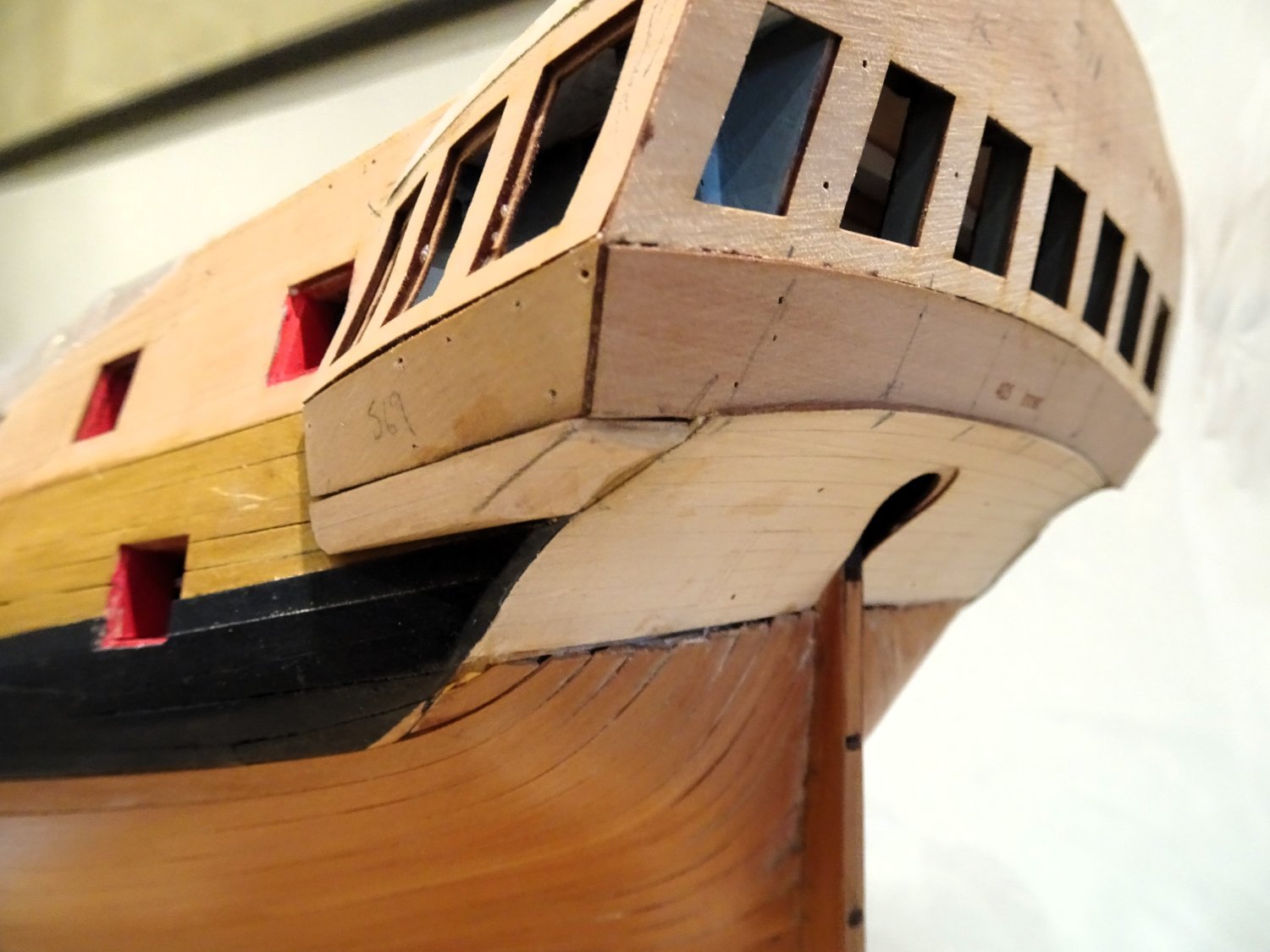
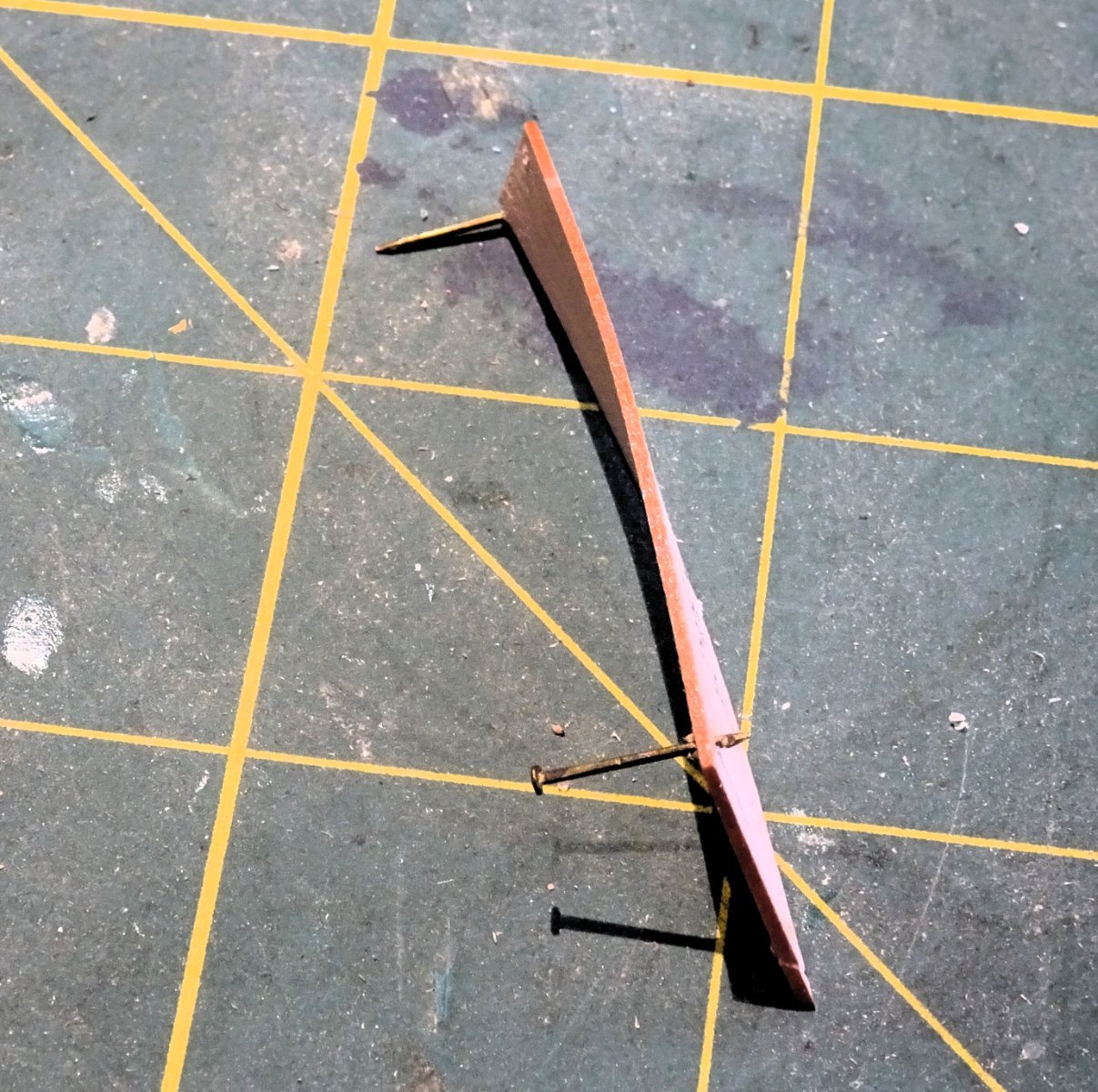
 Post Ninety-eight The Drops re-visited I couldn’t resist playing with the Drop blanks, and even with a touch of rounding look better to my eye than the resin equivalent. The originals had to come off the model despite the time and effort put in, but one should always be prepared to take a step back and indulge in a spot of light de-construction if you're not satisfied. 2501 2504 I think it’s something to do with the forward curve of the ‘ball’ and the more substantial appearance that at least to me suits the proportions of the Quarter Gallery better. 2506 2510 It will all look a lot better once the galleries are completed and the mouldings added. 2511 Hopefully, this is the end of the ‘Drop’ saga, I will leave the finishing until I return to complete the galleries. Movin’ on B.E. 24/10/2023


- 648 replies
-
- 24
-

-
- Indefatigable
- Vanguard Models
- (and 1 more)
-
Hi Glenn, Good decision, they are very useful when building the Vanguard ships boats, just the right pressure. My statement regarding James OOB build was not a reflection on your skills, I never thought it had Glenn, I have far more scope to play around with kits than James has in these circumstances, if I was doing the prototype, there would be a very long wait for any results. I have already de-constructed what I did yesterday/today, and am engaged in a spot of carving, or at least shaping. The story goes on... Regards, B.E.
- 648 replies
-
- 3
-
-
- Indefatigable
- Vanguard Models
- (and 1 more)
-
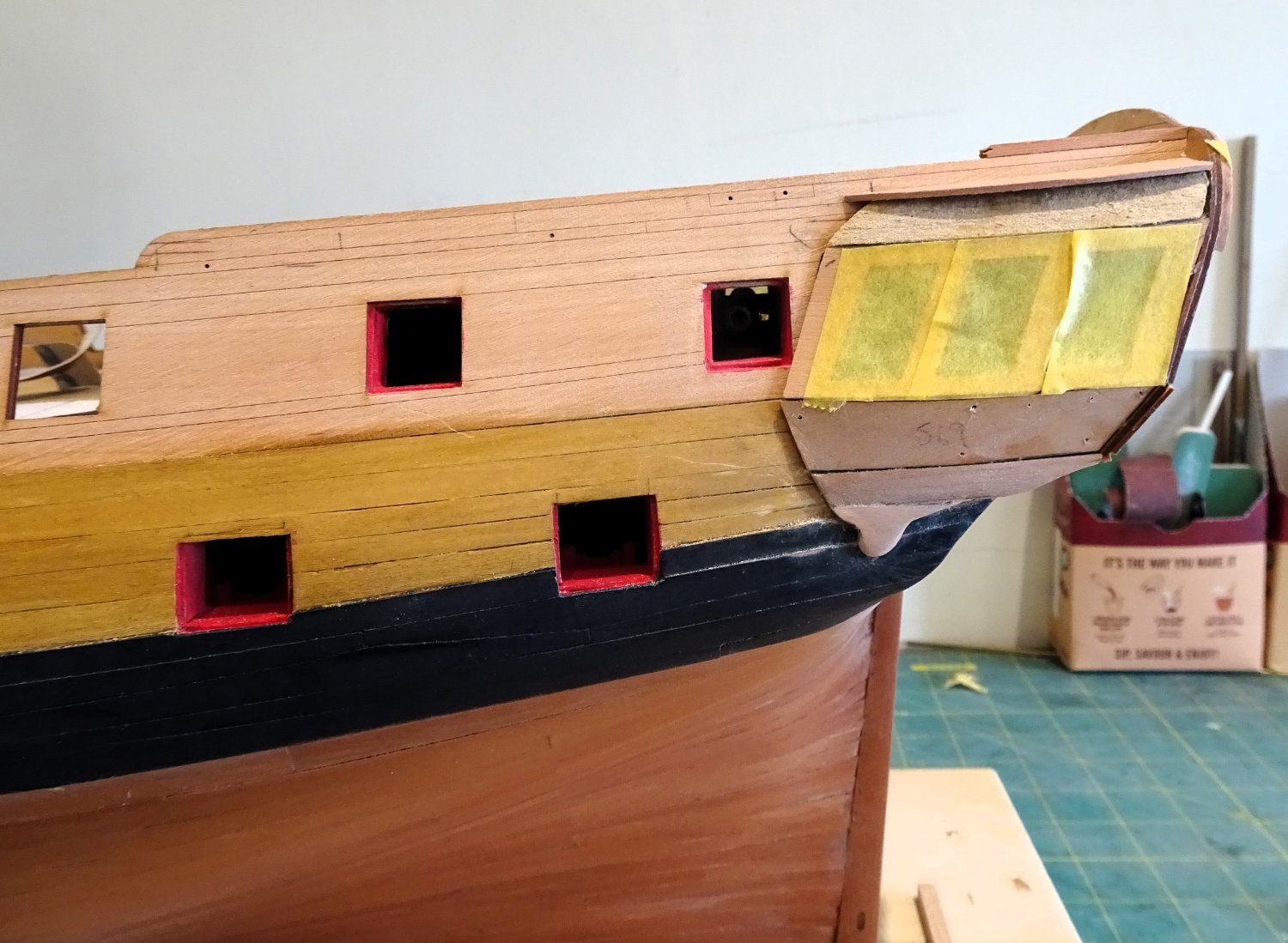
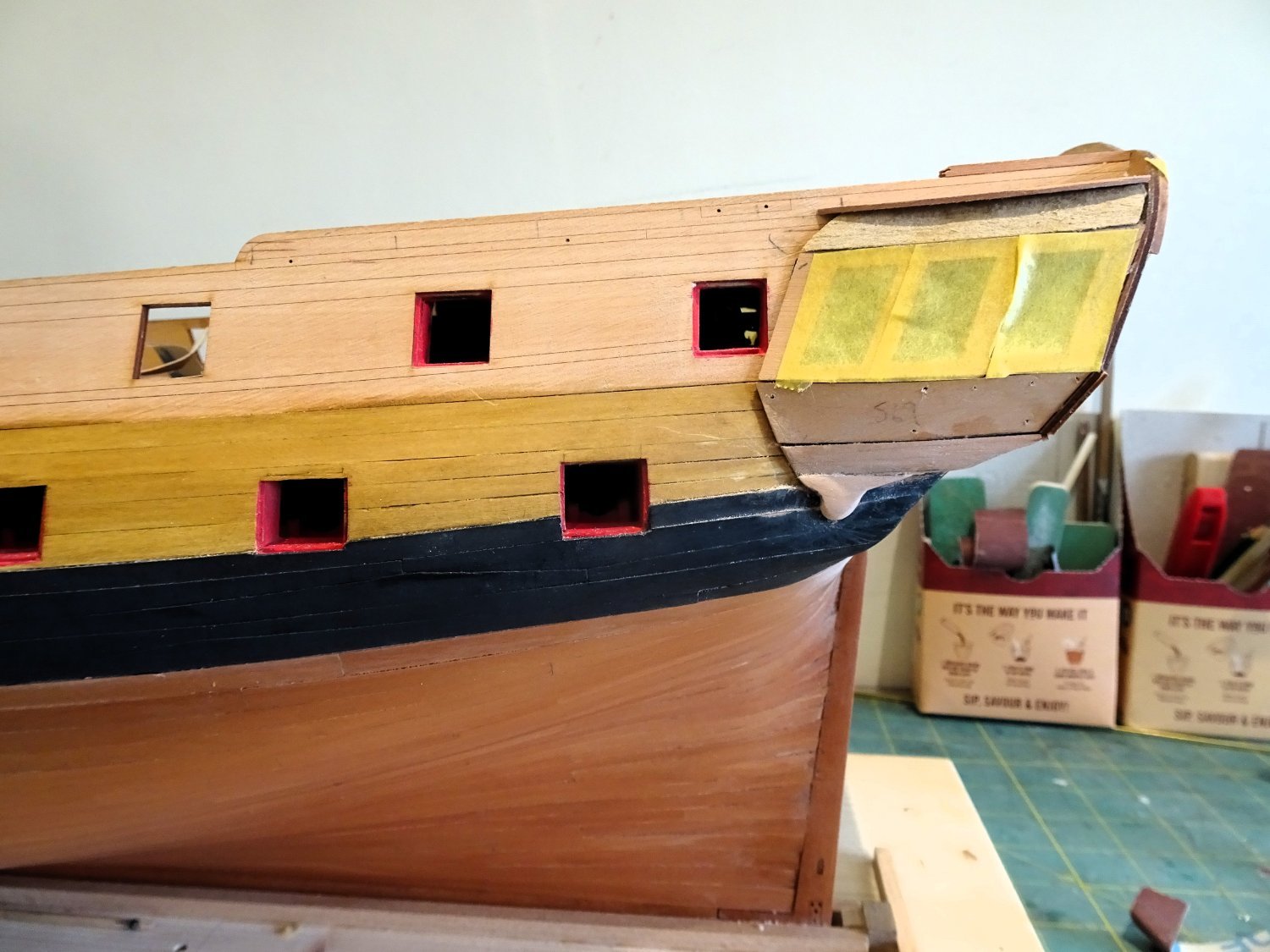
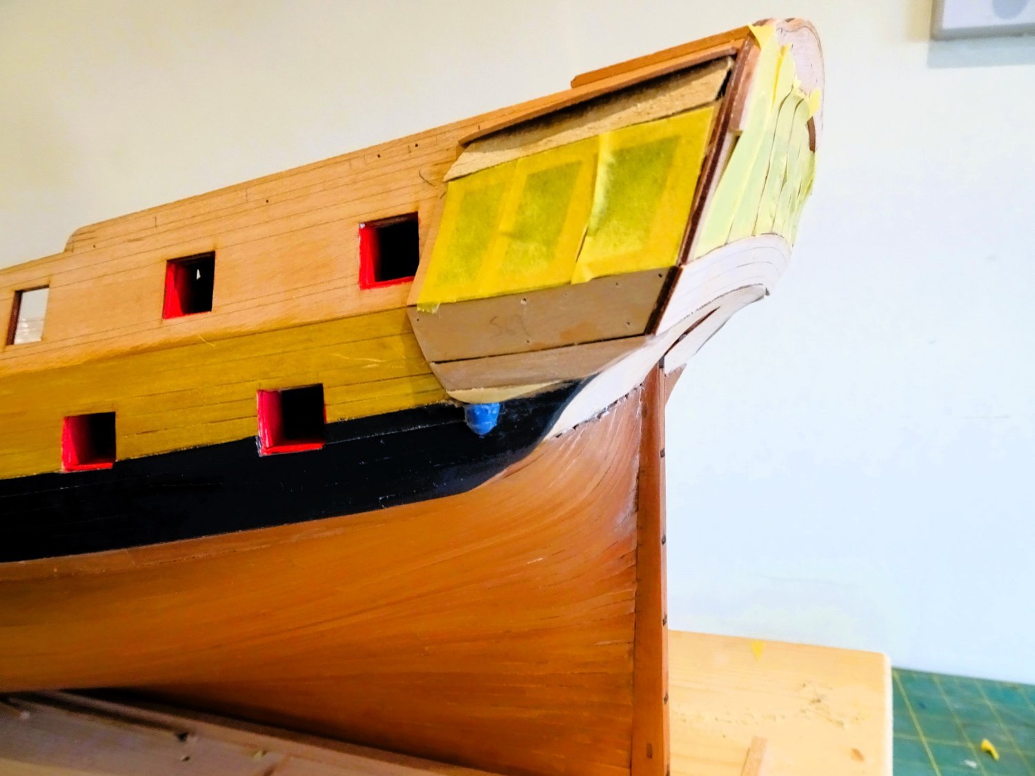
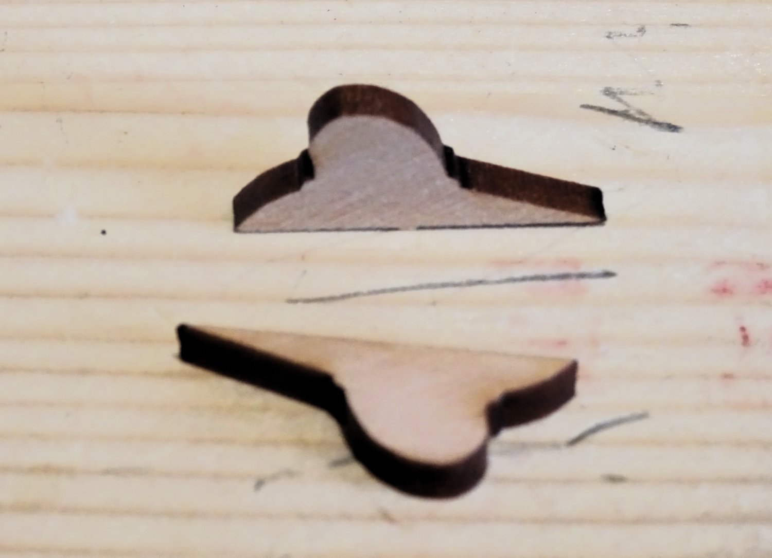
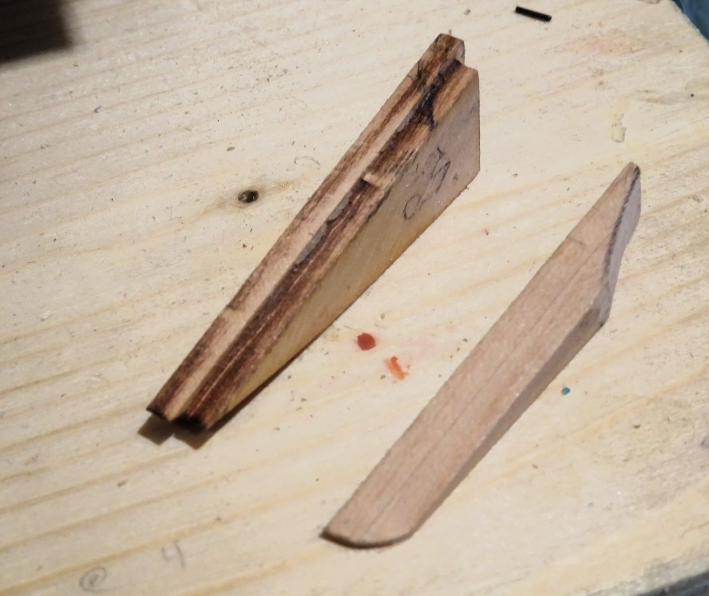
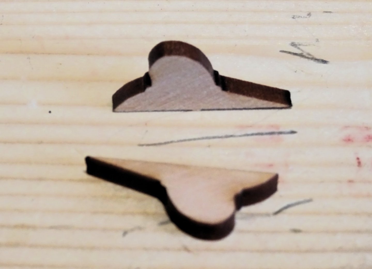
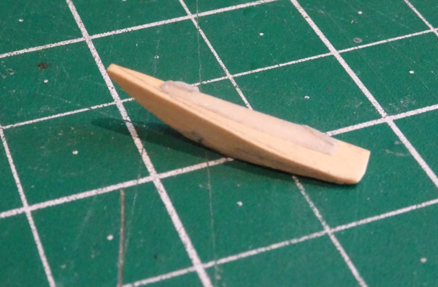
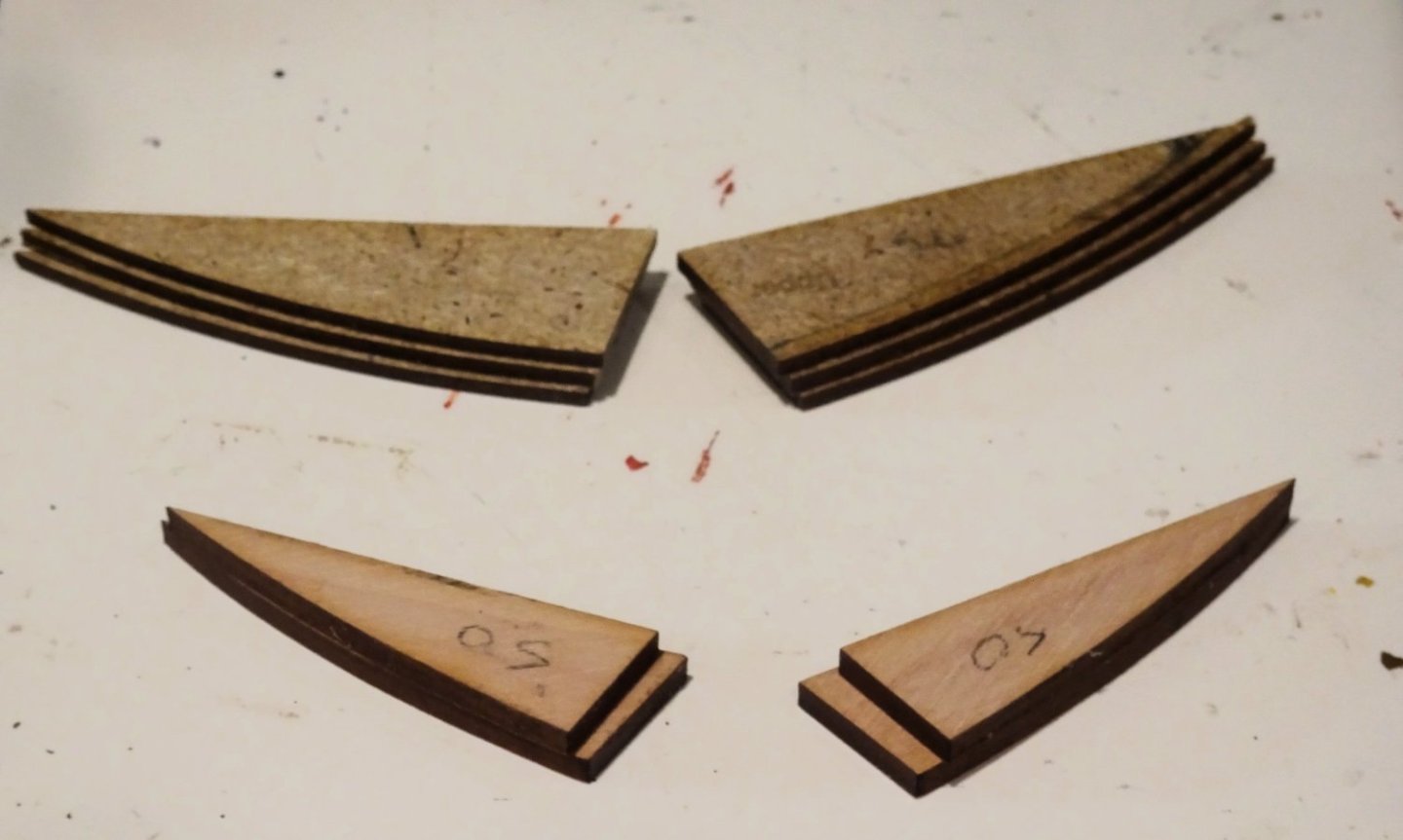
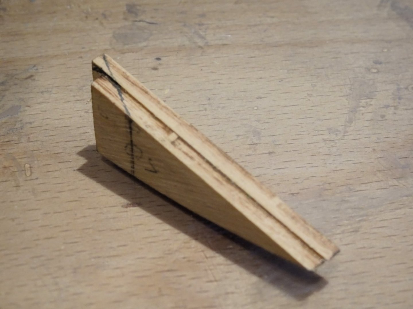
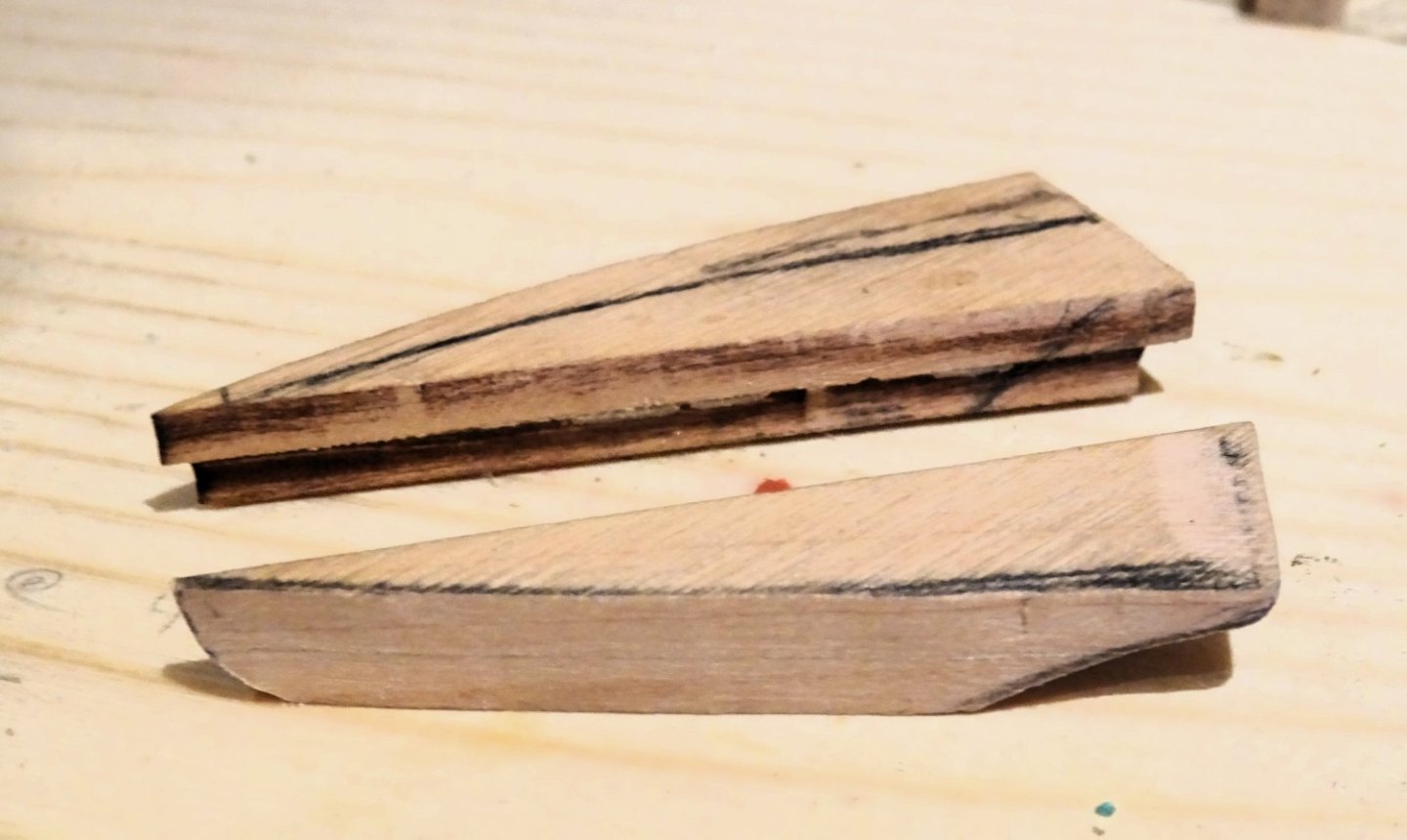
Post Ninety-seven Sorting the ‘Drop’ So, this is the aspired to effect. 2461 This is the Adm plan but the kit plan is much the same. 2479 I continued to tweak the drop to receive the ball. I am trying to avoid the effect of the ball seeming to sit directly beneath the level line of the Finishing. 2488 Starboard side Fiddling around with this stuff surely messes up the surroundings, but that’s to be expected. 2490 Port side The ball surface suffered a little on this side during the paring but I’ll sort that later. 2491 2494 2496 2496 There is a lot of cleaning up to do in the stern area, but now the drop issue has been resolved in my mind I will move onto the Quarterdeck planking. Ahrrrrg.😒 Having moved on and looking for something else I came across these little items that look suspiciously like ‘Drops’. 2498 These are parts 51 on the 3mm pear sheet, mentioned in the index, but not in the Gallery construction pages or the prototype build section 636. Perhaps Chris decided to replace these blanks with the resin item. Still, they are the correct shape to fit beneath the Finishing, and I wish I had found them earlier. I may have to re-visit the Drops, but even if carving the ball is not fancied, the upper part could be used in conjunction with the resin ball. B.E. 23/10/2023


- 648 replies
-
- 10
-
-
- Indefatigable
- Vanguard Models
- (and 1 more)
-
Cheers Thuky, I'm much more comfortable with wood, avoid filler wherever I can. As Harry Callahan said - A man's gotta know his limitations. B.E.
- 648 replies
-
- 2
-
-
- Indefatigable
- Vanguard Models
- (and 1 more)
-
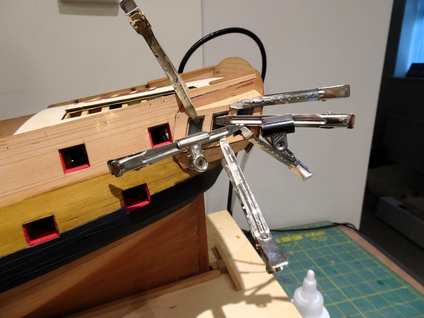
Hi Glenn, The sectioning clips are particularly useful where a light hold is required but additional pressure can be applied using stronger clips along the arms. The aluminium ones can be bent into shapes to provide holding points. Of course, I looked closely at the prototype build and the drop didn’t quite look like the plan, and what I know of how these things are set up. James is obliged to build a strictly oob build to match the contents, and the manual, on the principle of what you see is what you get. The manual does acknowledge a possible struggle to shape the base and suggests clipping the base away, gluing the ball in place, and build up the base using epoxy putty. Personally, I didn’t fancy creating such a complex shape on the model using putty, particularly in the awkward place it is. Others may have a higher skill set. Cheers, B.E.
- 648 replies
-
- 3
-
-
- Indefatigable
- Vanguard Models
- (and 1 more)
-
Thanks Andy, I did try them every which way, but the ball is nearer the fore end than the aft end in accordance with the plan, so there is only one way. I will persevere. Cheers, B.E.
- 648 replies
-
- 2
-
-
- Indefatigable
- Vanguard Models
- (and 1 more)
-
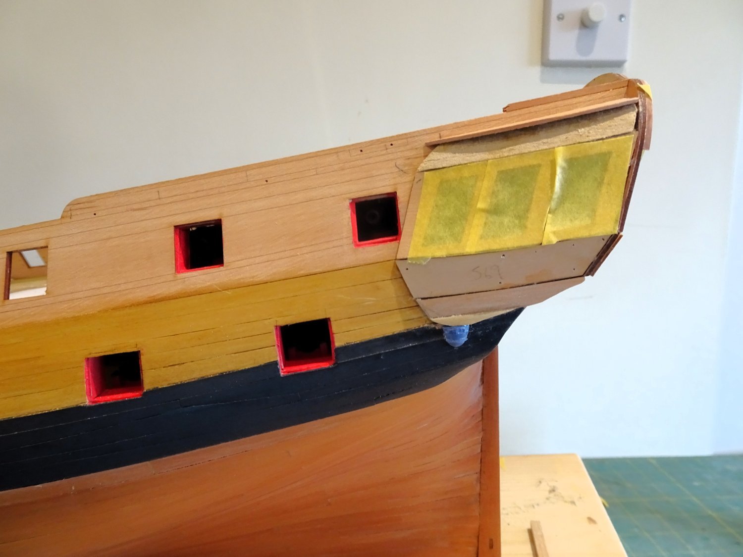
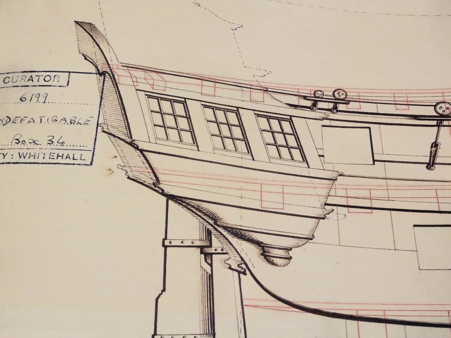
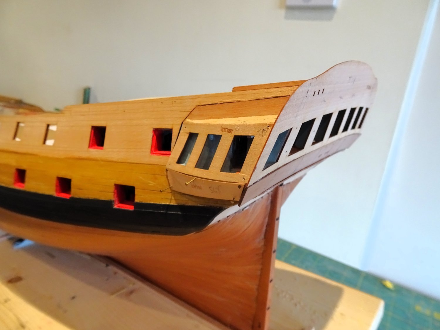
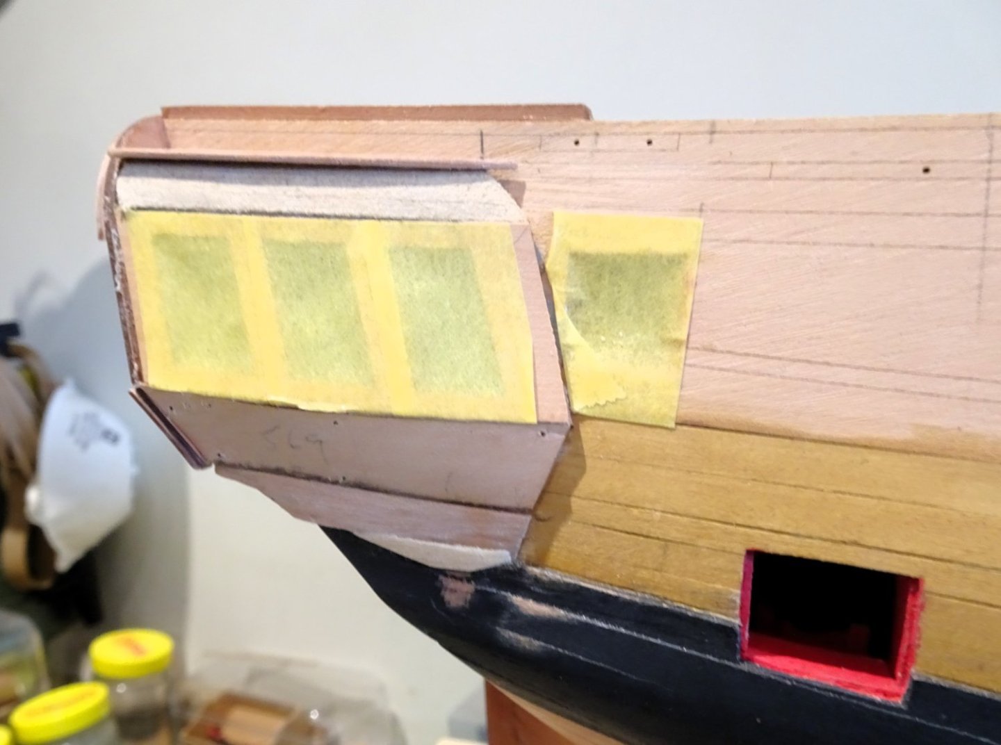
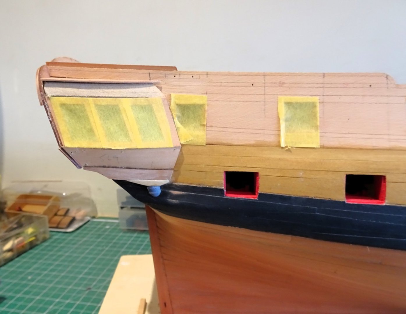
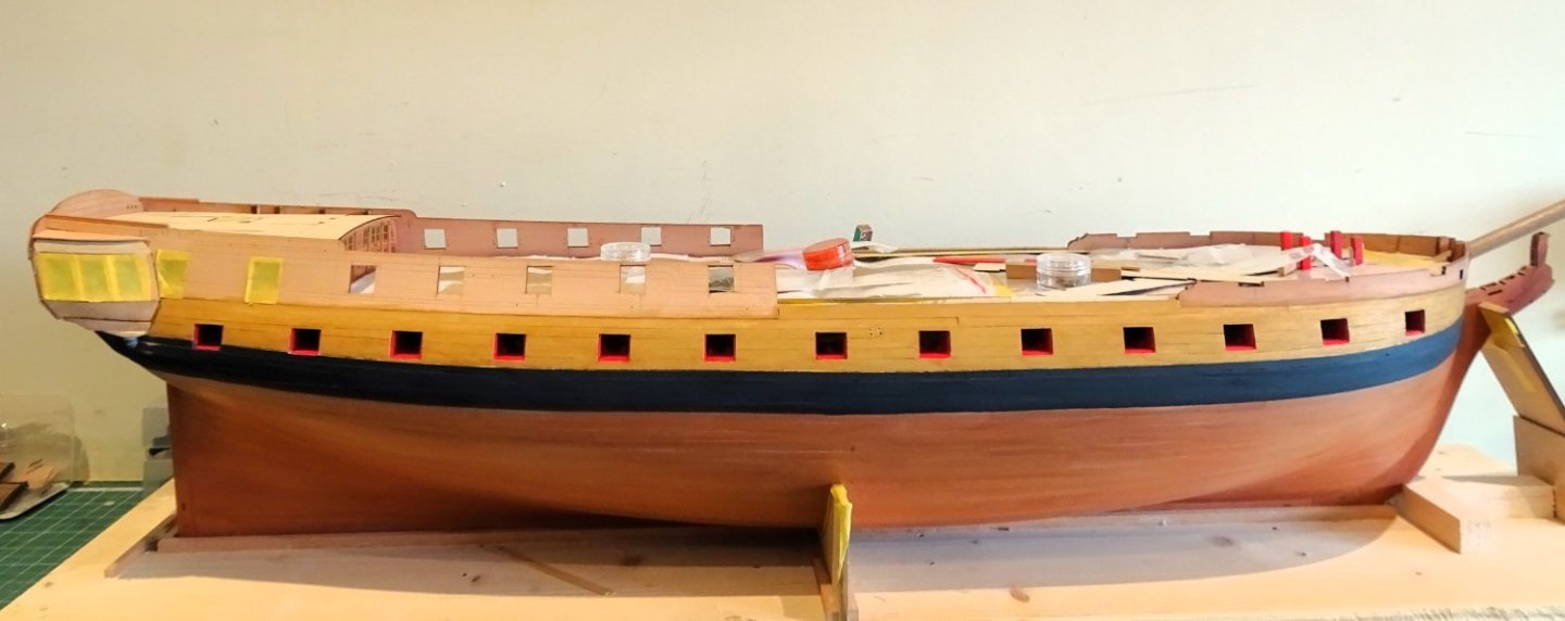
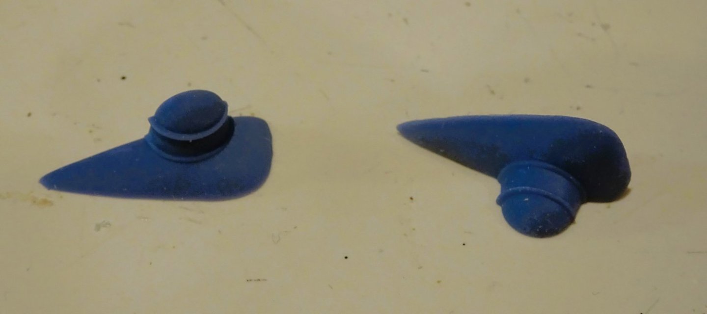
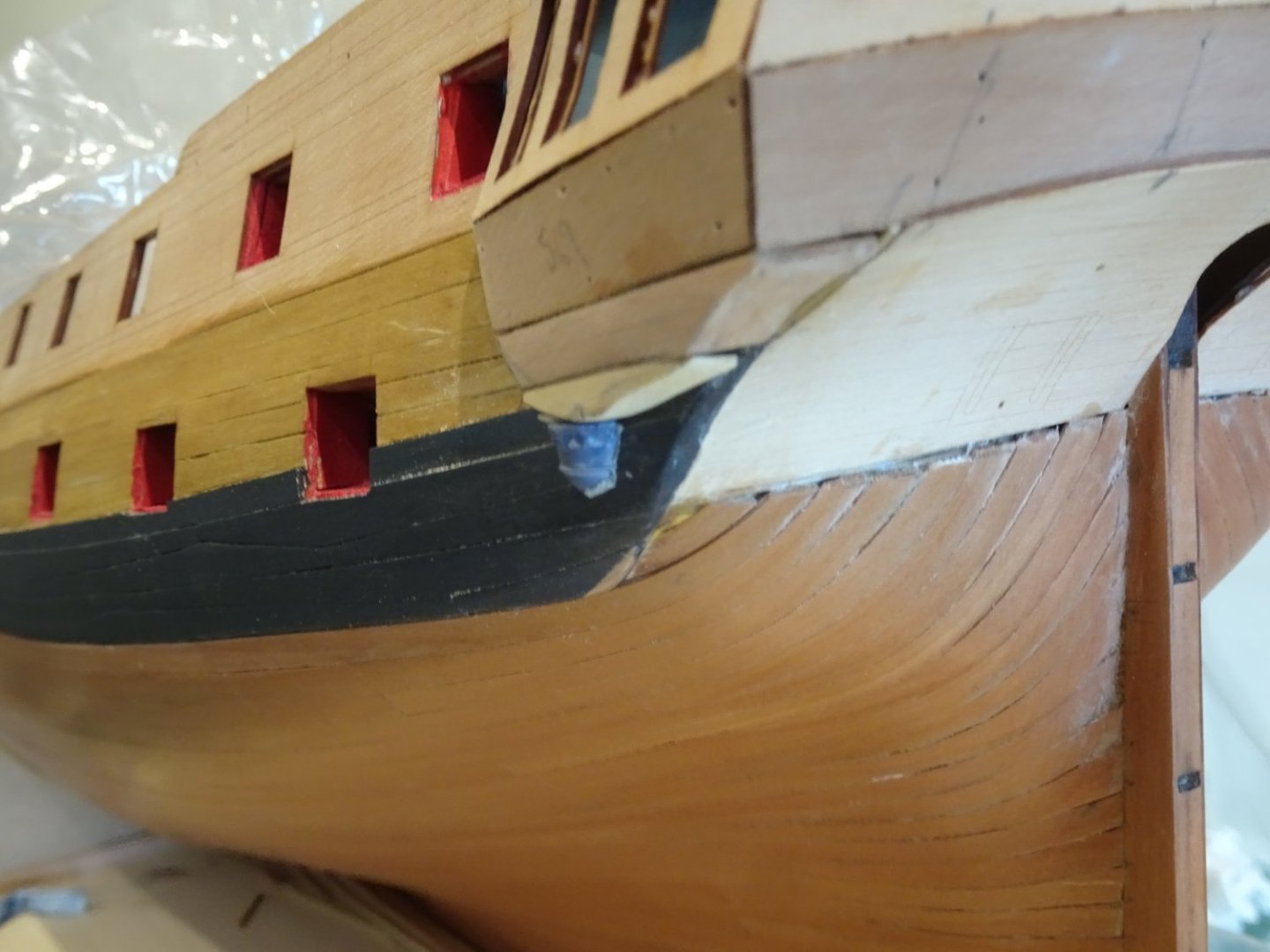
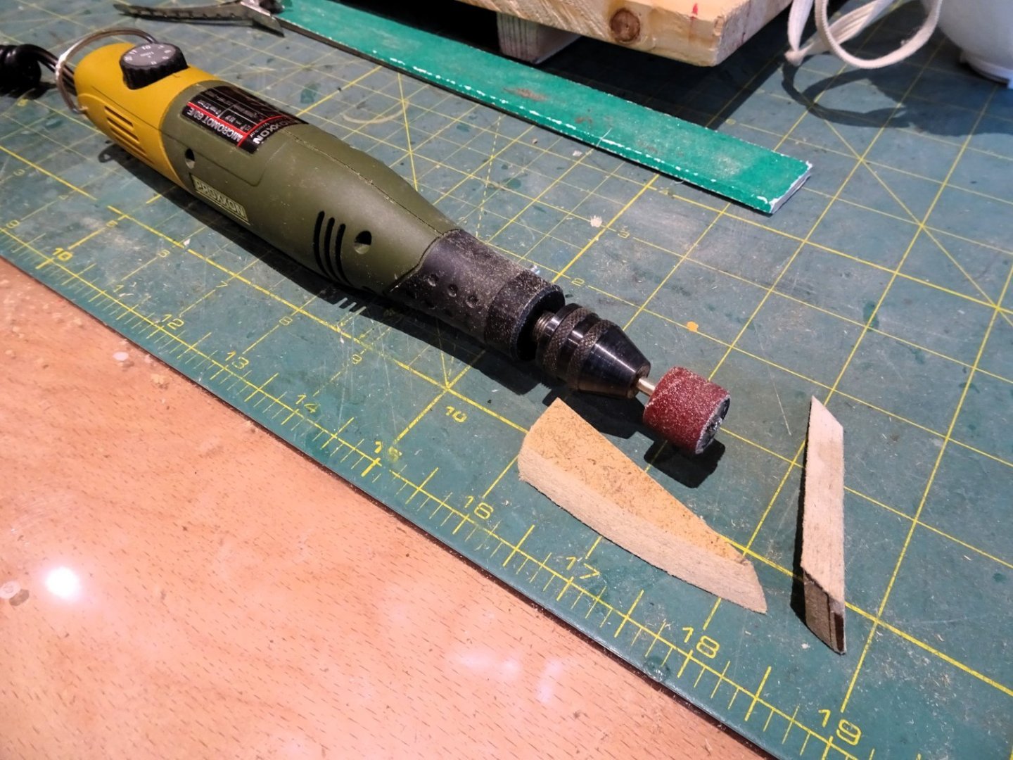
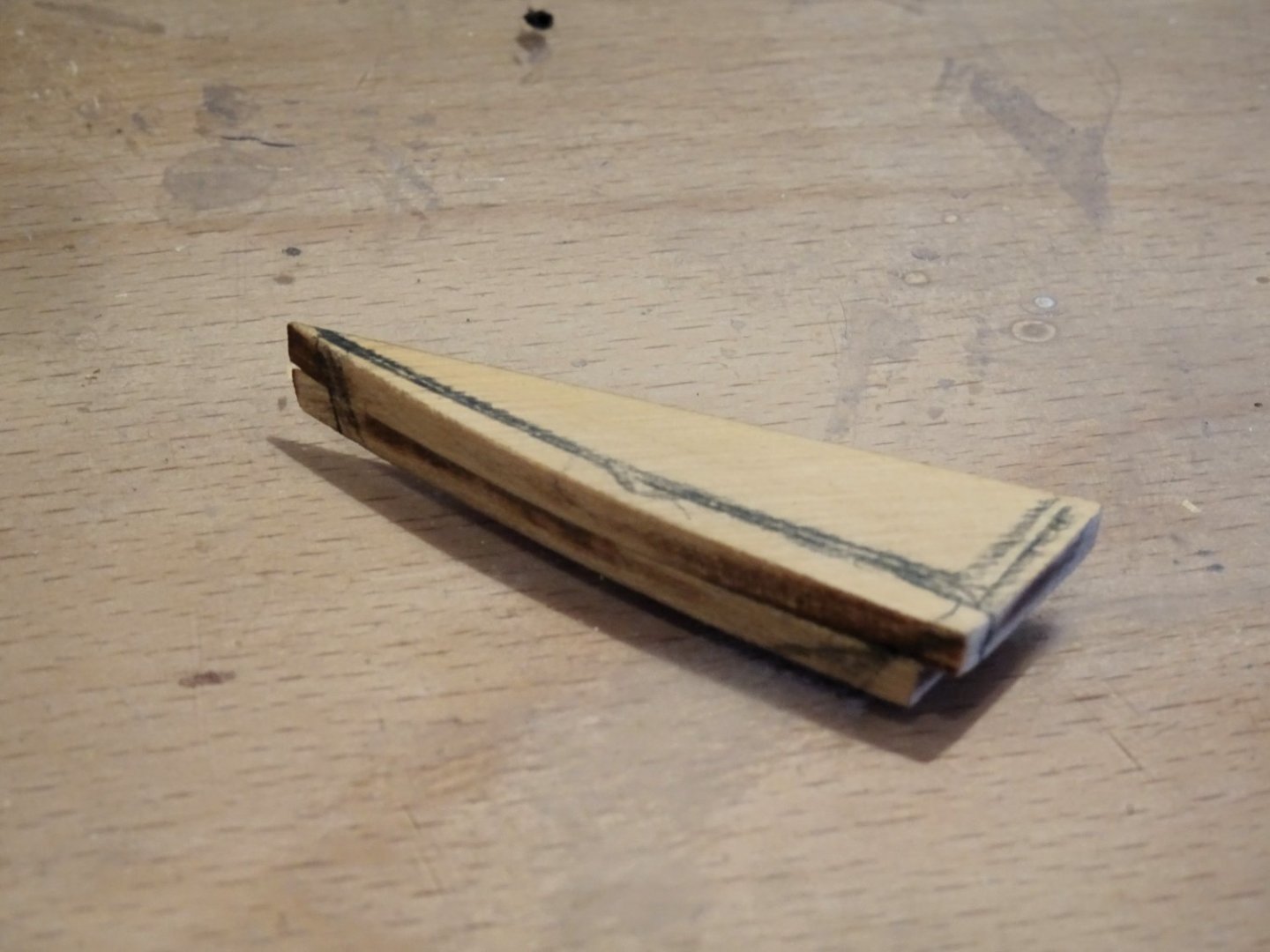
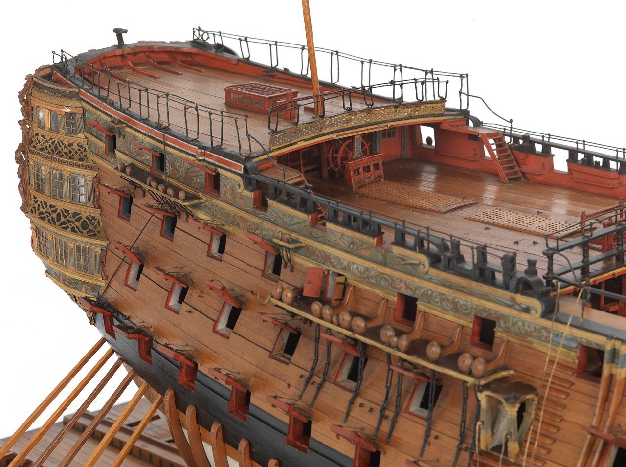
Post Ninety-six The ‘Drop’ Is that fancy little decoration that sits below the lower finishing. 2461 In earlier times this was a more fancy affair than that adorning Indy. 2439 Chris has provided a resin version which at first sight I thought would save a lot of scrap wood and an excess of murmurings on my part. However, the resin drop is described as ‘generic’ in the manual, and attractive as it looks it seems to be the wrong shape to fit the Lower finishing. 2458 2459 It is at its broadest where the finishing tapers towards the forward part of the gallery, and any width reduction threatens the lower ball decoration. I snipped away at the part but could not get something that looked right either in terms of the kit plan or the official Adm plan. (as above) 031 My shipyard assistant gave it close scrutiny and was not too impressed either, so we both failed to see how this could possibly work. I think the issue is that the part instead of curving downwards to meet the ball, is shaped outwards beyond the width of the lower edge of the finishing. If it needs to be cut away to the point of destruction, there seems little point in having it. Still, this is classed as an advanced kit so I should be expected to handle this sort of thing.` 2472 Using 6mm x1mm Boxwood I laminated four strips together and started to shape a replacement that better reflects the plan. 2467 The ‘ball’ was cut away from the resin part and thinned down a little from the back. 2468 I’m getting there but not happy yet. I need to fine down the drop attachment to allow the ‘ball’ to sit a little higher up the wale. I think I’ll be playing around with this for a while yet. 2474 On a brighter note the stern gallery looks superb, and it all lines up as designed. At this stage I’m starting to get a frisson of excitement about the build. B.E. 22/10/2023


- 648 replies
-
- 20
-
-
- Indefatigable
- Vanguard Models
- (and 1 more)
-
I love the stuff you produce Chuck, my Cheerful and Queen Anne Barge are two of my favourite models, and the Longboat which I have yet to complete. To put things in perspective, I am currently building the Vanguard Indy at a cost of around $2000, and I’ve spent way over that in additional timbers, and other associated costs. I am able to indulge my interests, but even so a completed cost of $2300 seems perfectly reasonable for such a special pof model, and my younger self would buy it in a heartbeat. I think it would look very nice simply as an ‘in frame’ model, all that beautiful timber work to display. I think you would also have great success with a pob version. I can’t commit to a purchase as I’m in the twilight years of my modelling career, but then I did buy Indy, never say never eh. B.E.
-
Neat job Alistair, she looks good.👍I found the Pinnace the trickiest to build as well. I hope your health is improving. Regards, B.E.
-
Pleased you like it Cold Fire, and thanks for looking in. Regards, B.E.
- 648 replies
-
- 1
-
-
- Indefatigable
- Vanguard Models
- (and 1 more)
-
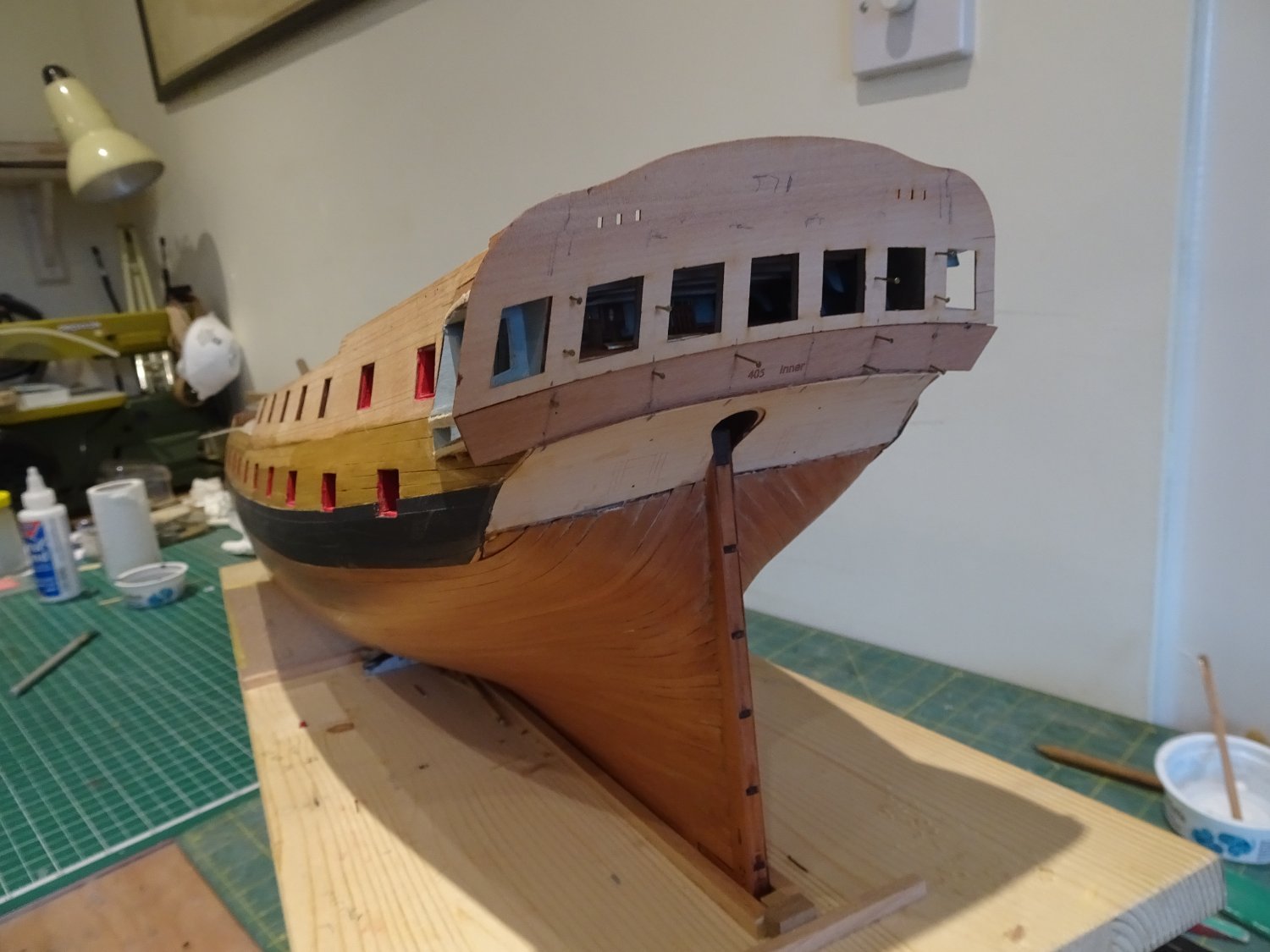
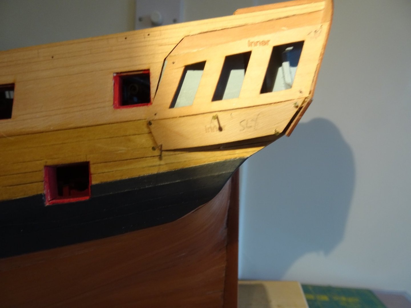
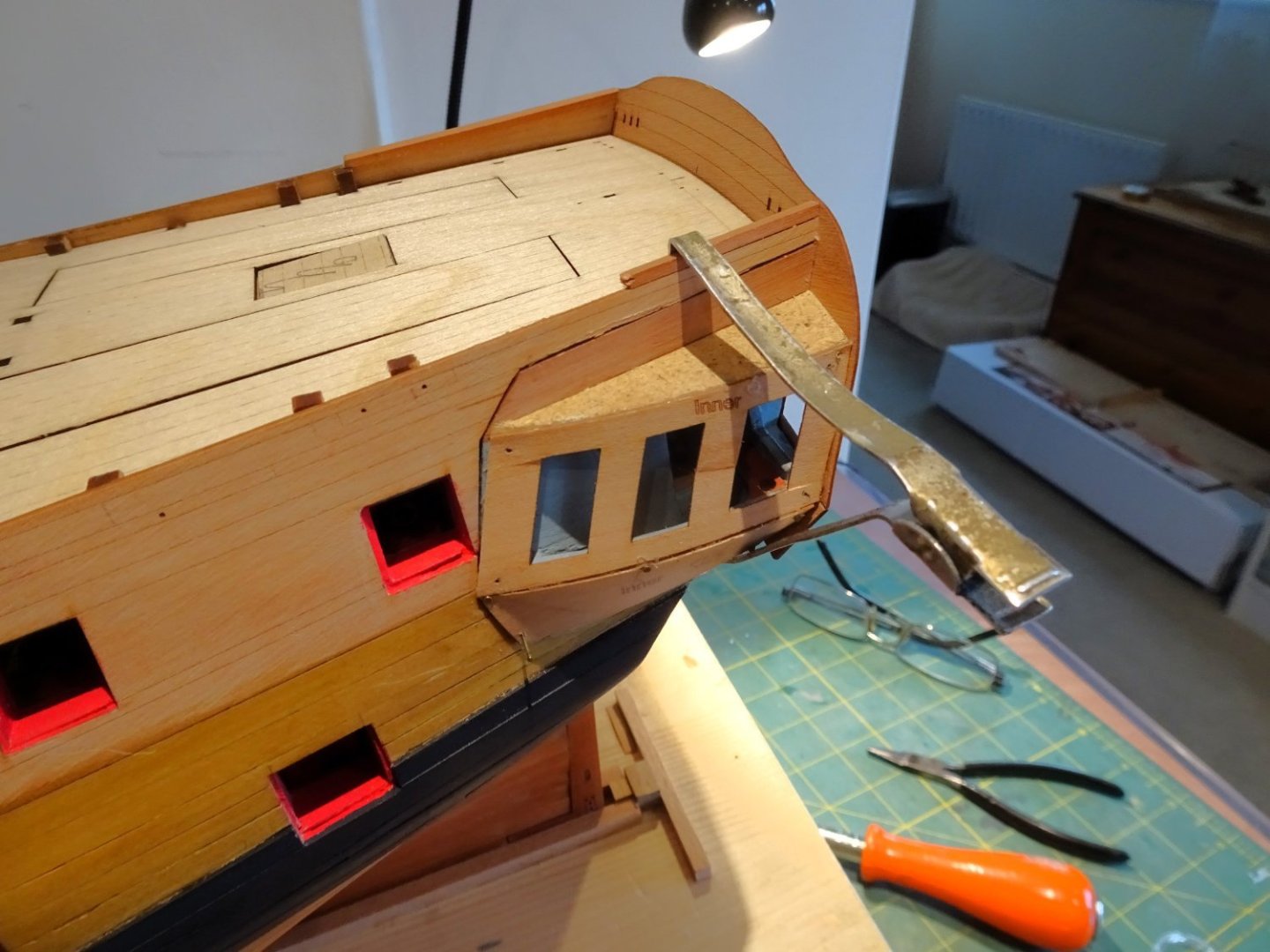
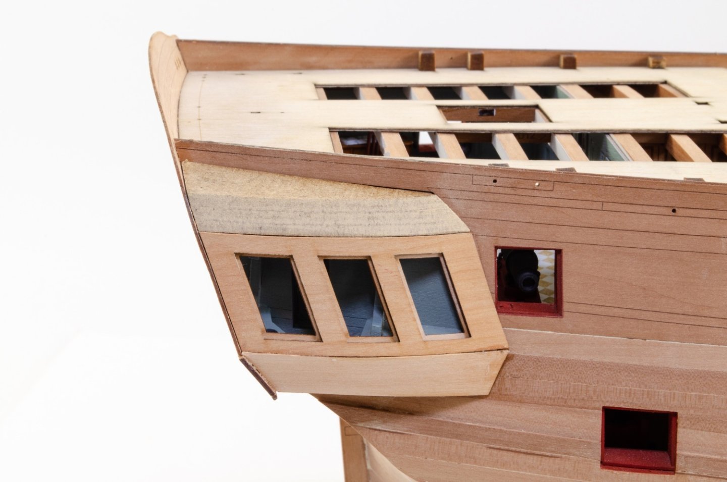
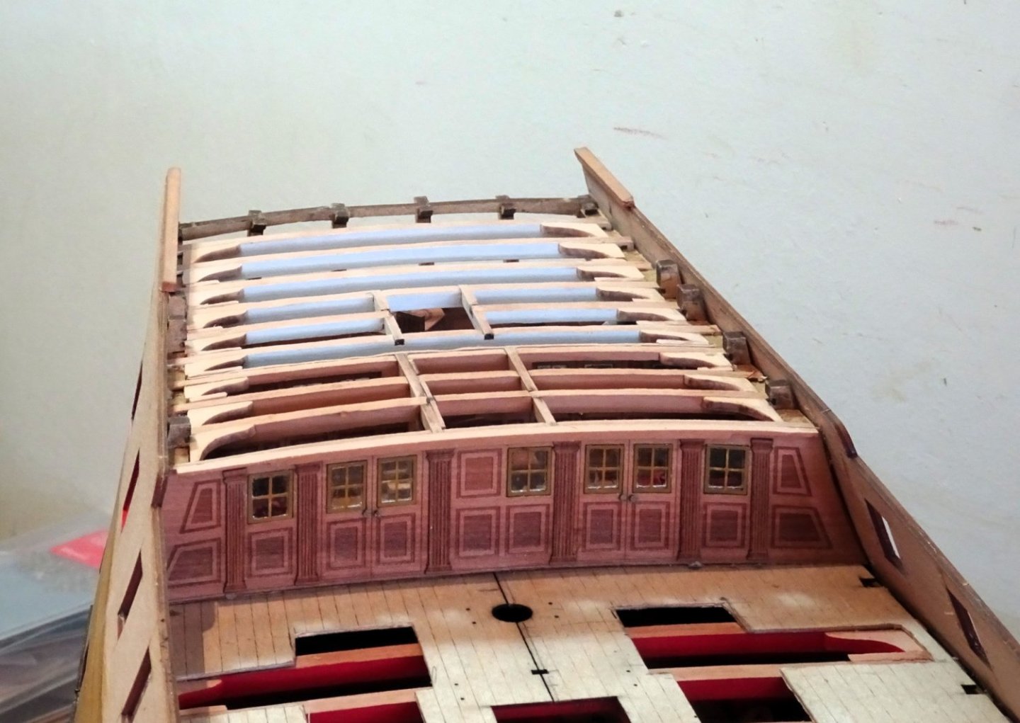
Post Ninety-five Galleries cont’d The outer patterns for the gallery mullions are a perfect fit. Again, I dry heat bend them to conform to the shape. 2436 One must get inventive to hold the parts in place. I find these sectioning clips a great aid to modelling. 2447 For the finishing outer pattern, I found it necessary to pin to hold the part in place until the glue set. At least the gap has now gone. The next tricky element of this section is shaping of the laminated roof and lower finishing of the Quarter Gallery. 2442 The roof requires a sharp clean chamfer on the front edge, a bevel on the aft edge to meet the transom, and a sharp angled edge on the fore side. This is done in a series of steps, mark, sand, re-mark, and check. 2443 The completed items together with the means of achieving it. The lower finishing requires careful shaping to avoid it looking like a lump of stuck on the bottom. The detail is shown on plan sheet 6. The parts fit neatly between the Upper finishing and the Black Strake. 2450 2451 2454 With the part in place the shape can be roughed out in pencil. Initially I am not inducing any taper from top to bottom, concentrating on getting the width and curve to match the lower counter. 2453 A degree of taper is then introduced. 2455 2456 Still held in place with double sided tape at this point but getting close to the completed shape. Fairly satisfied with progress, but there may be trouble ahead. B.E. 21/10/2023


- 648 replies
-
- 19
-
-
- Indefatigable
- Vanguard Models
- (and 1 more)
-
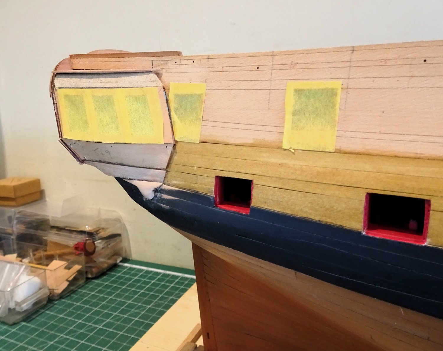
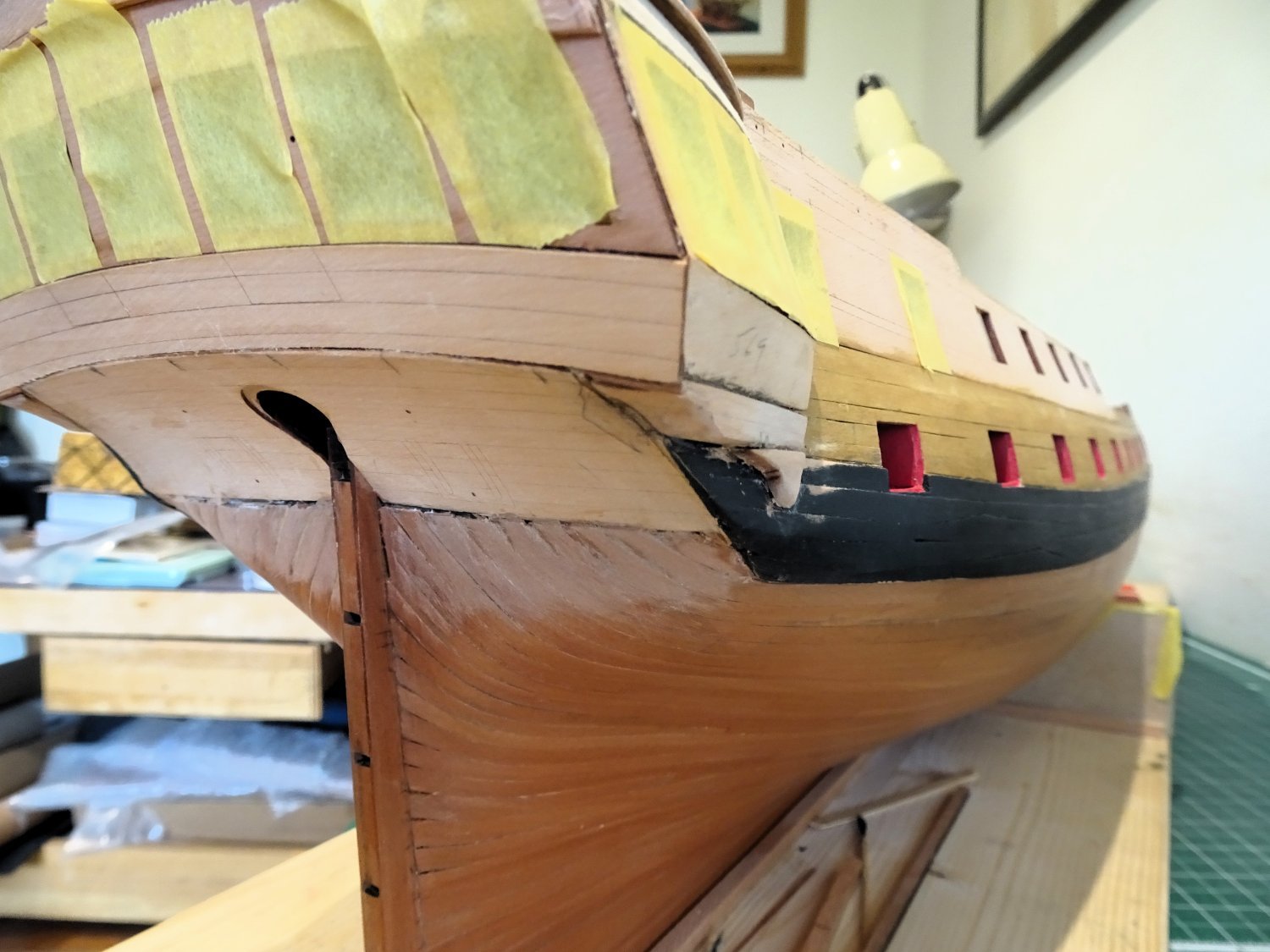
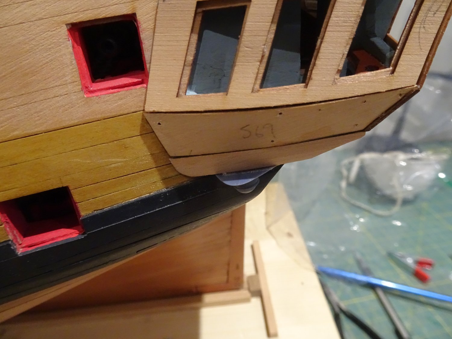
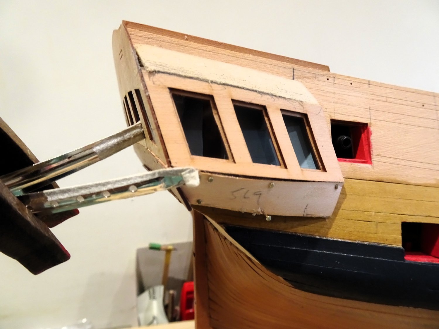
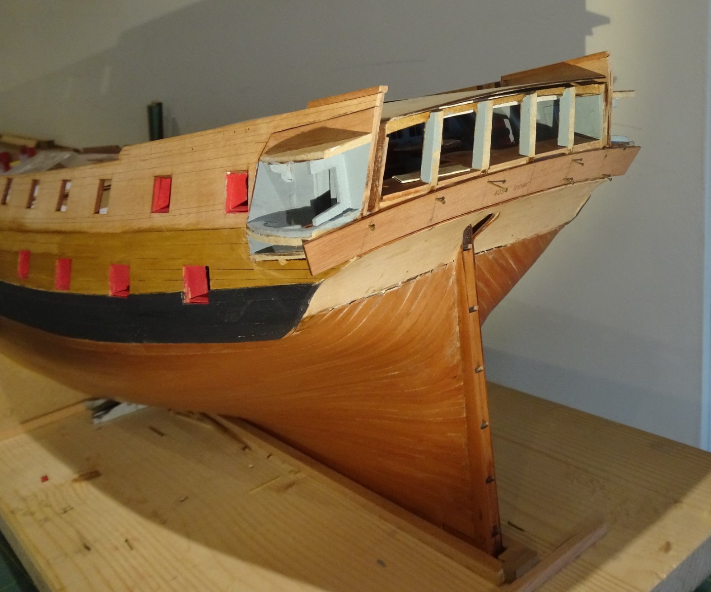
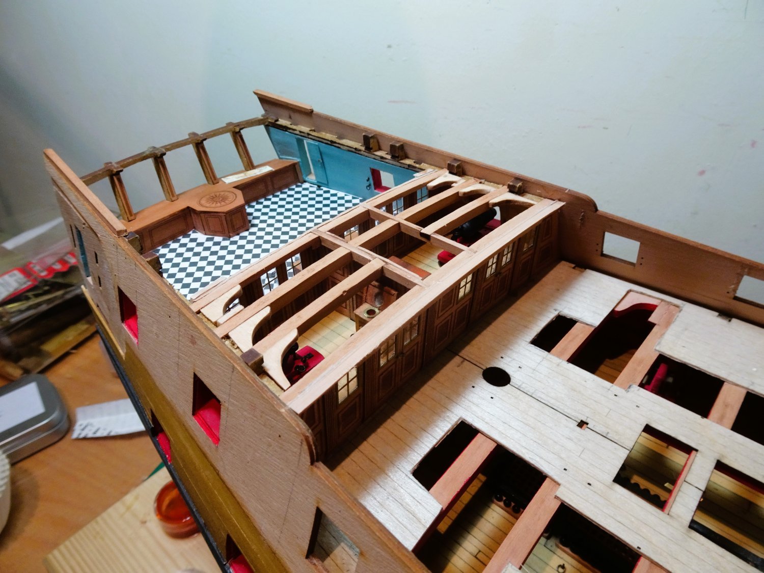
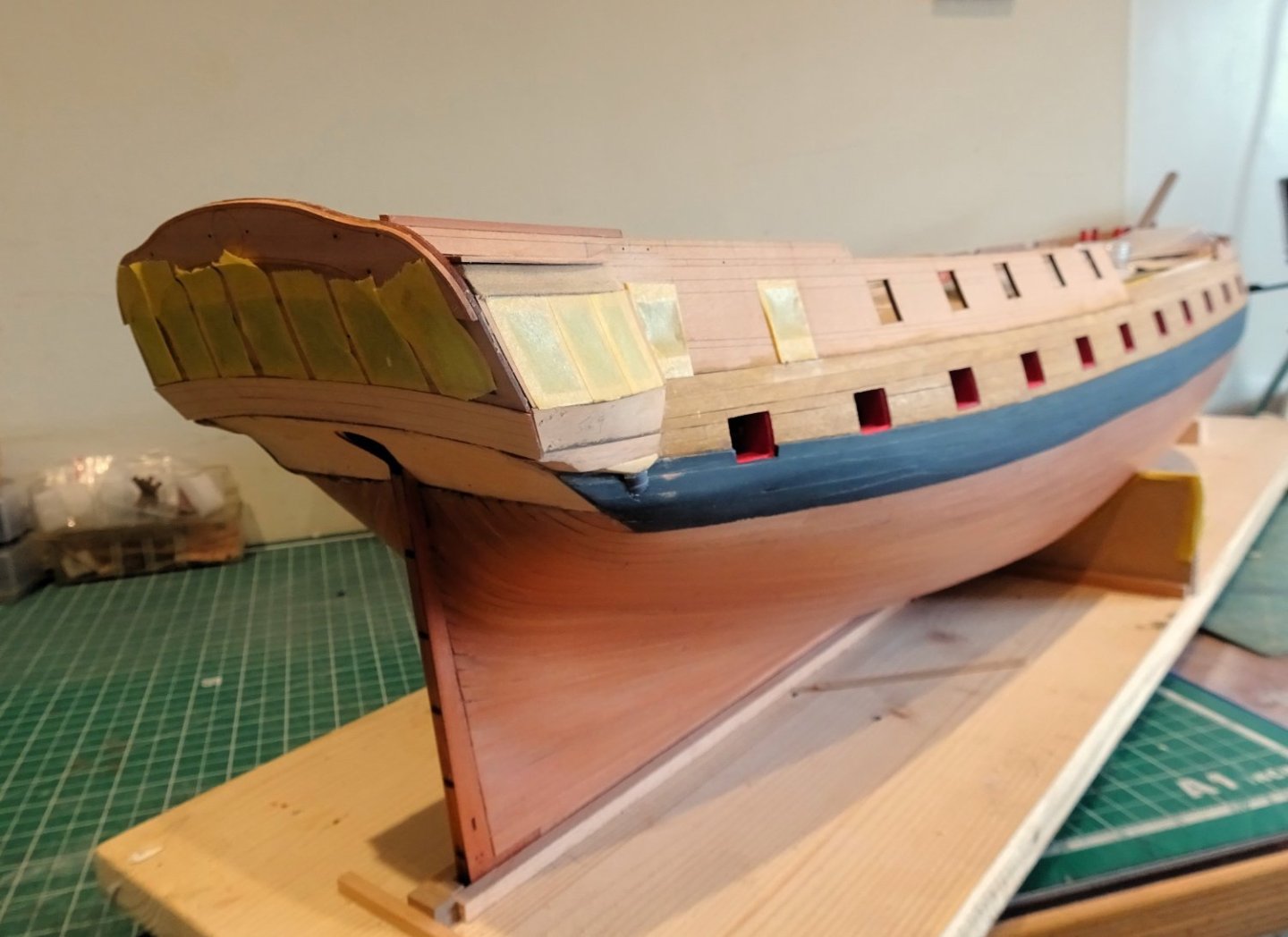
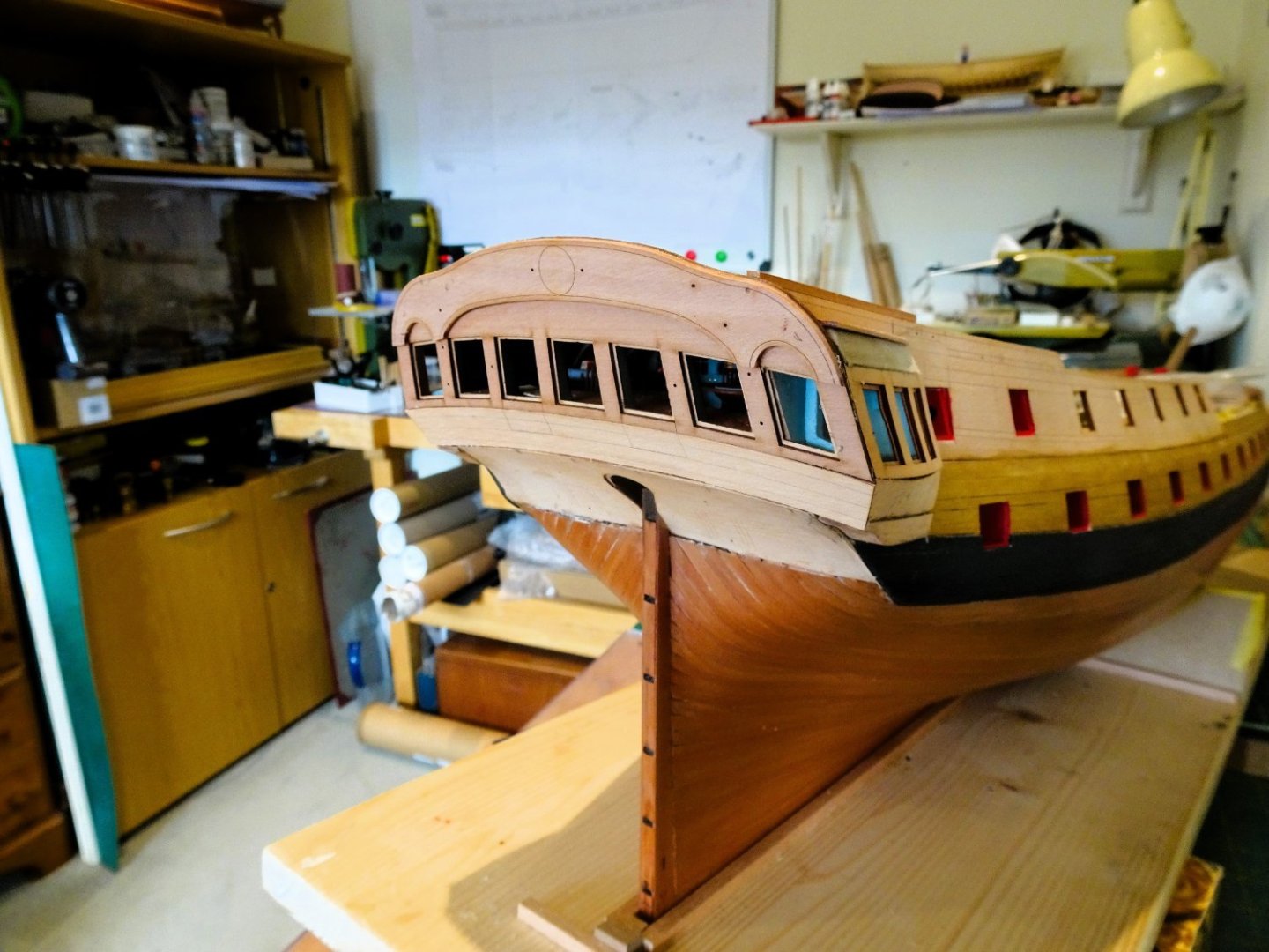
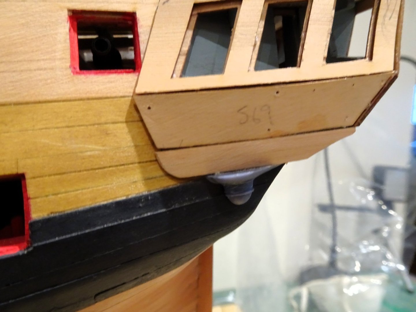
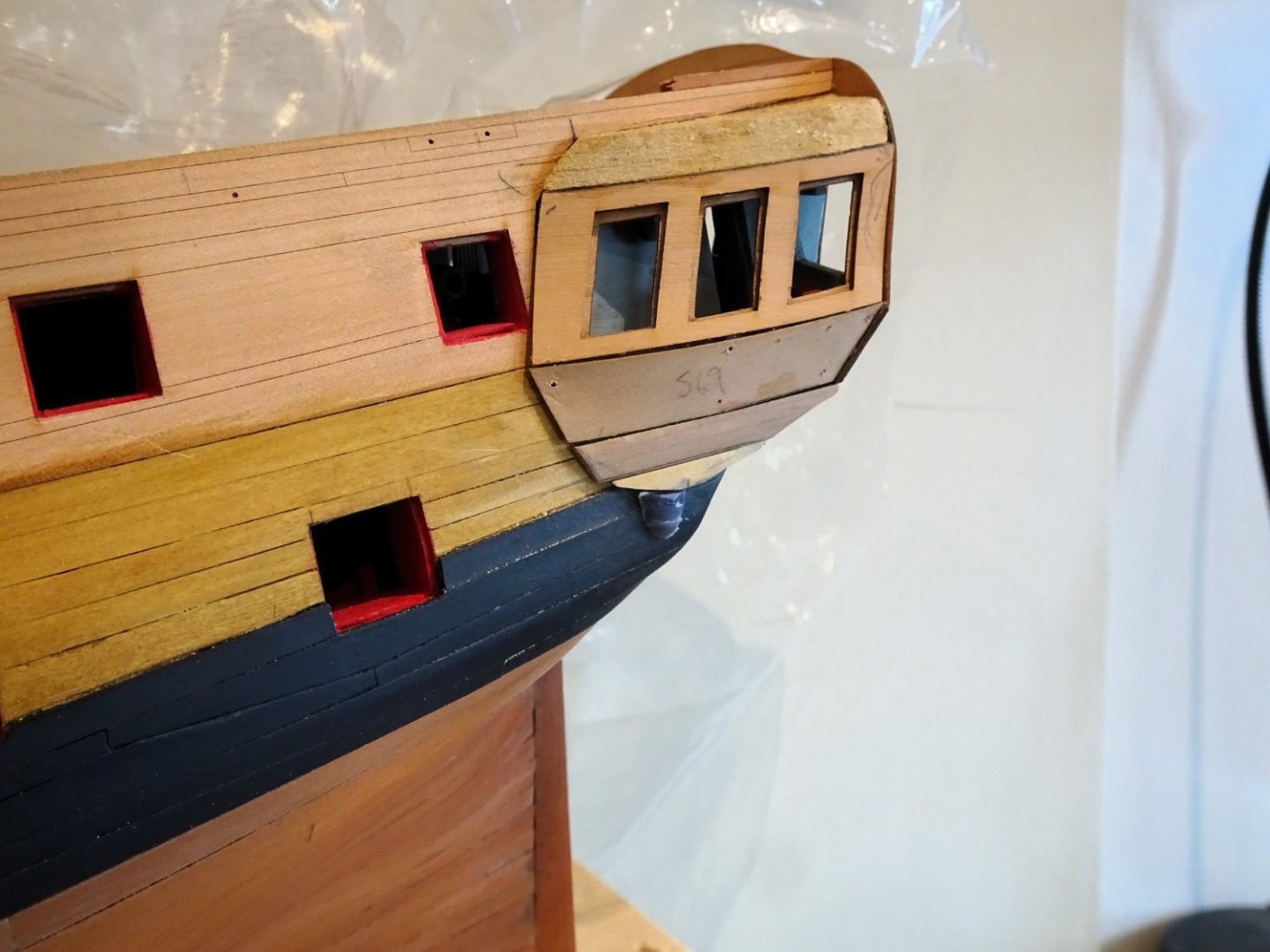
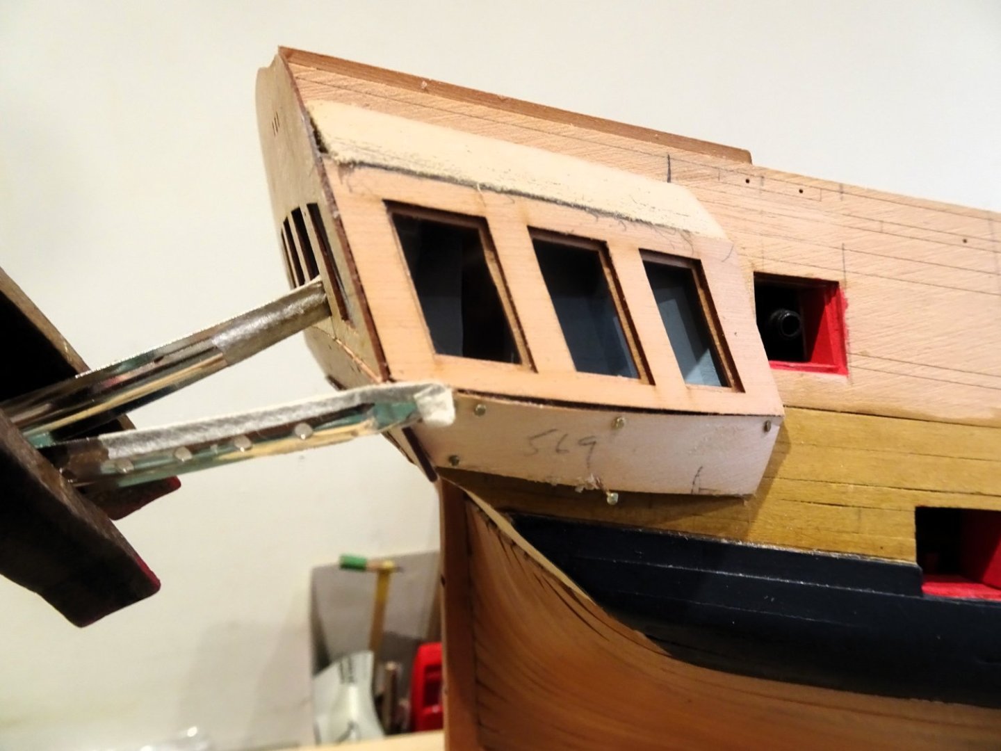
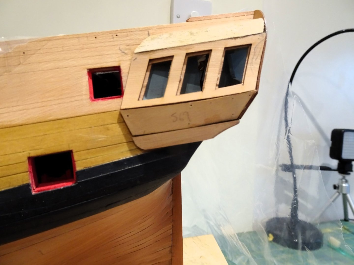
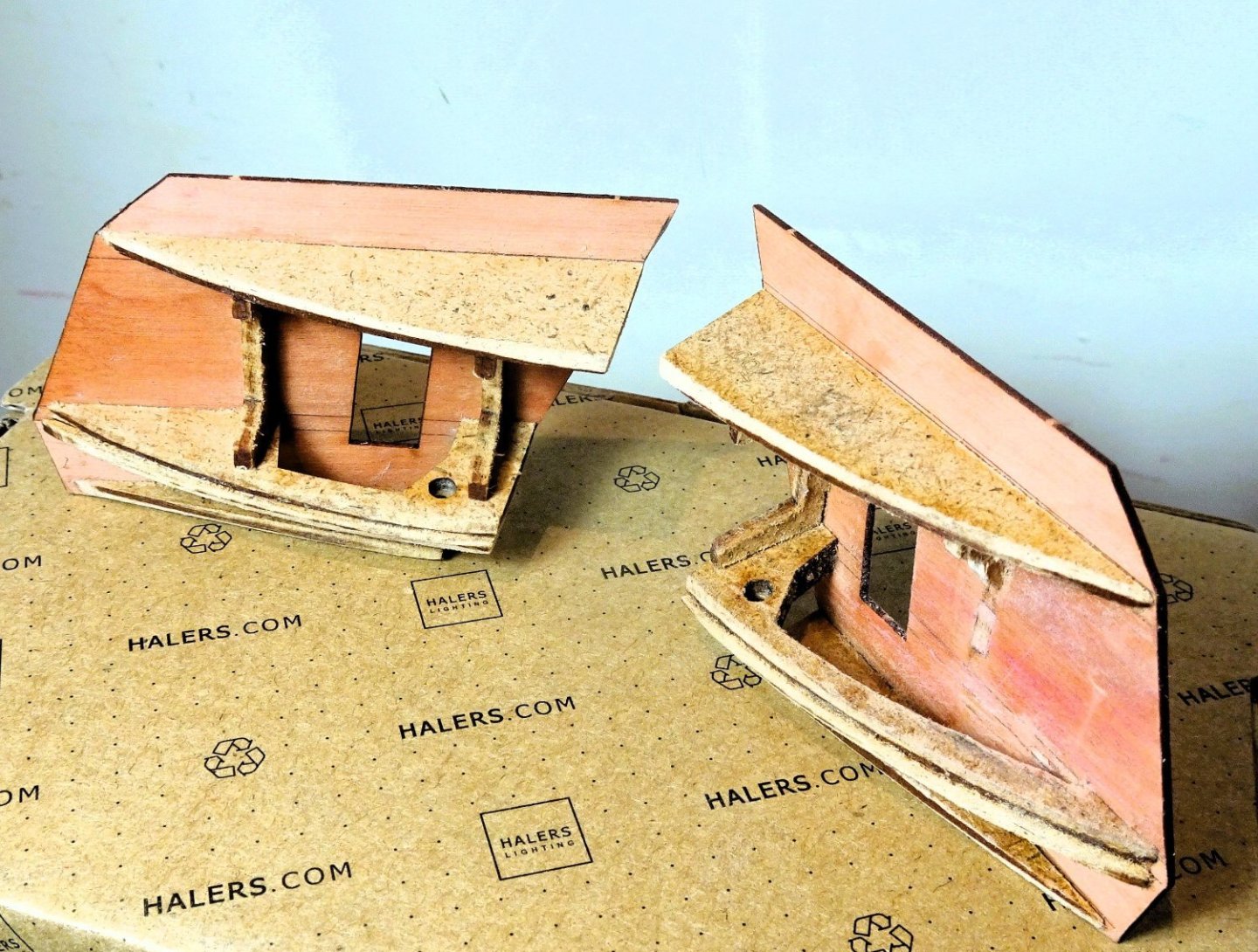
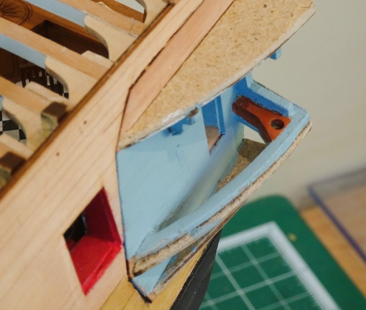
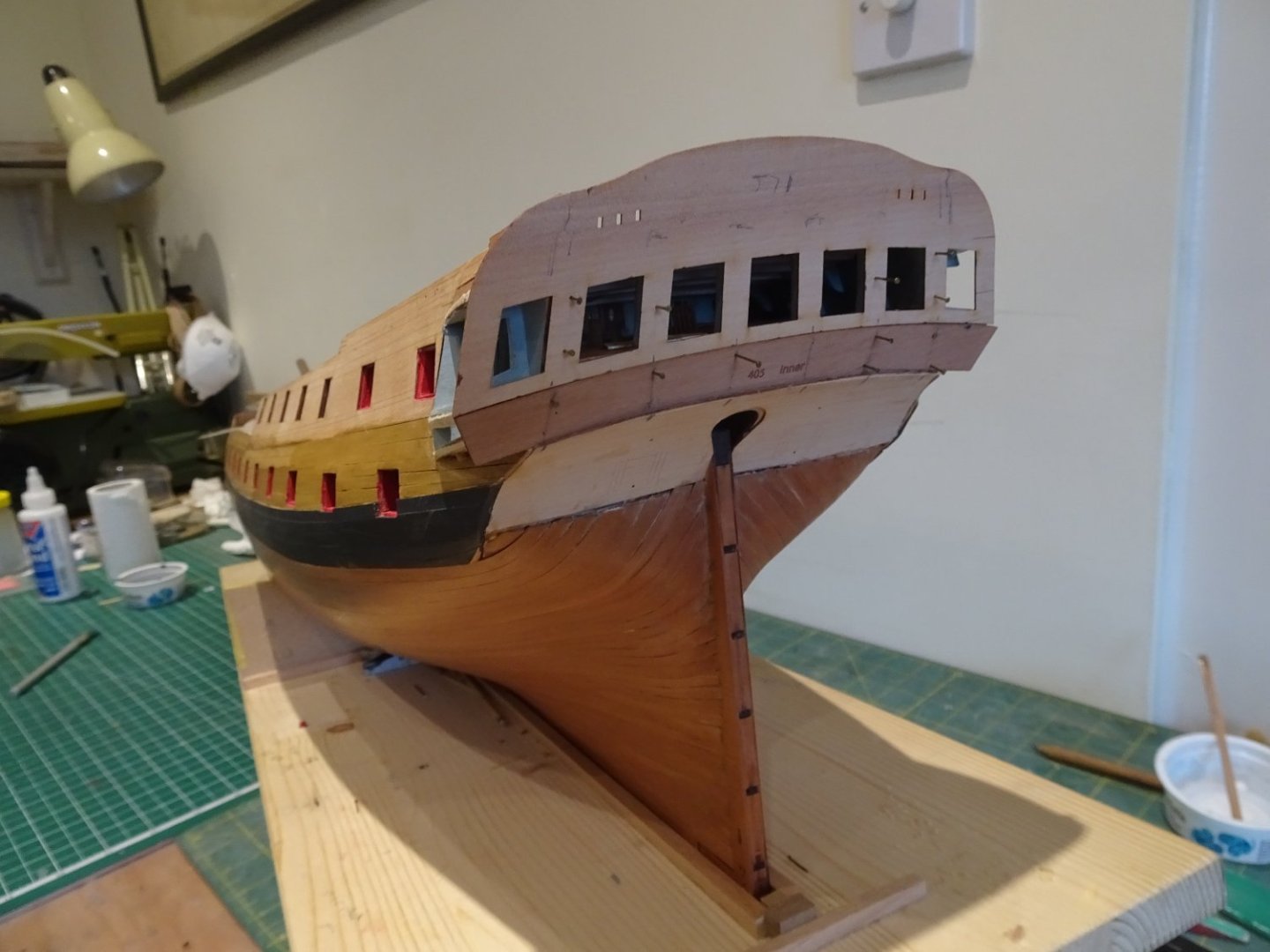
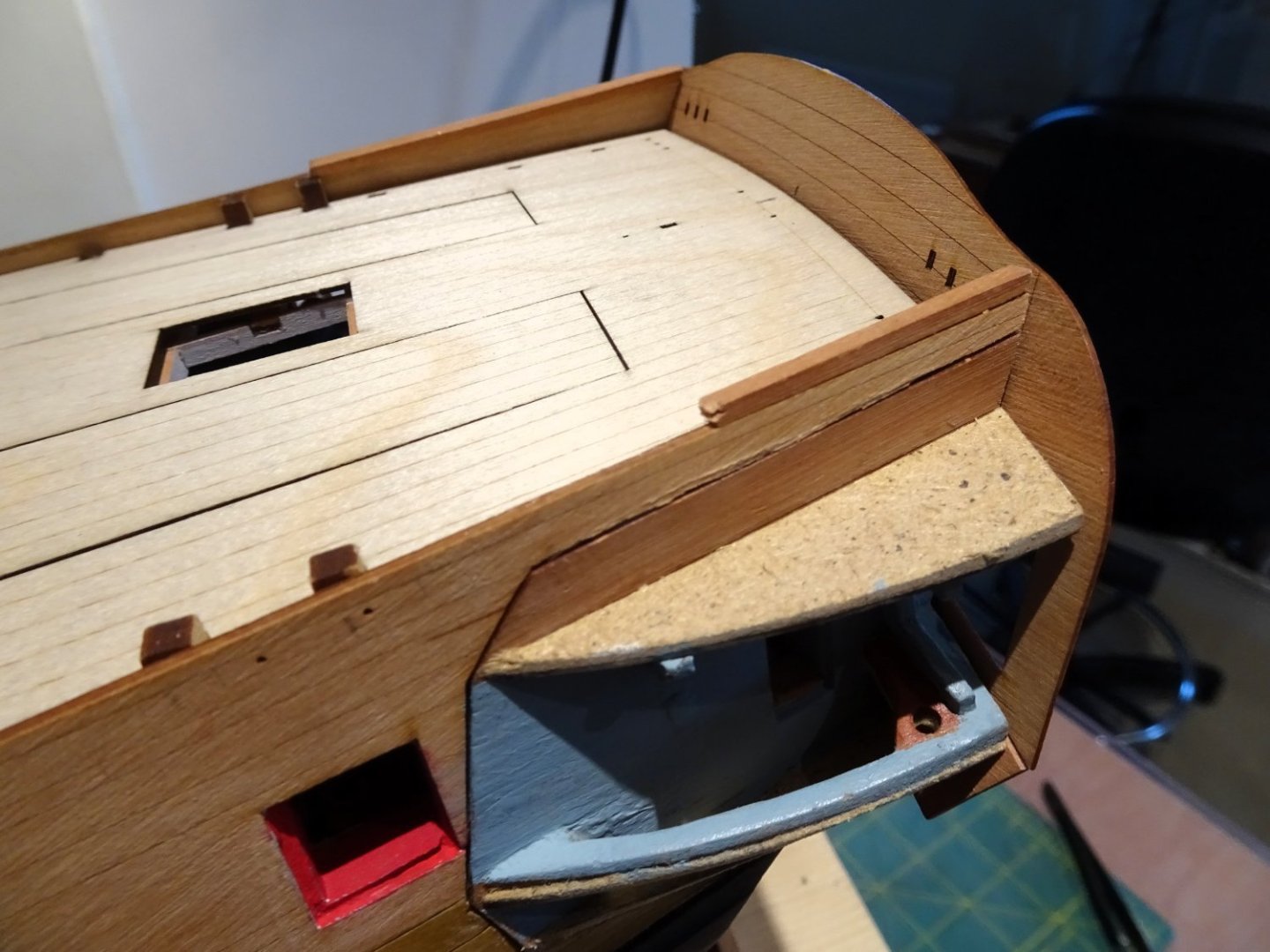
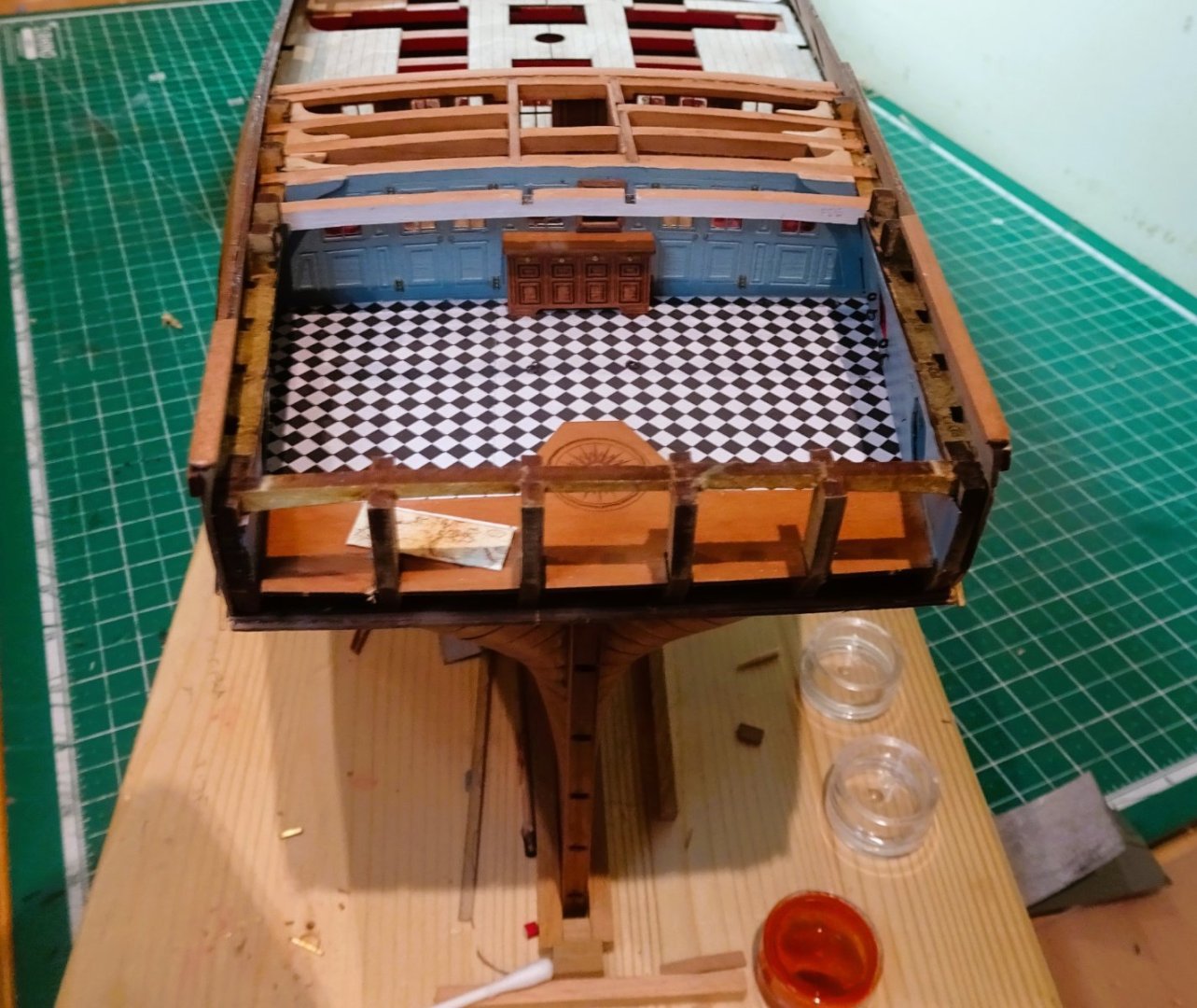
Post Ninety-four Stern and Qtr galleries. This is a critical area of the build, and no matter how many times I have done it before (which is quite a few) I still feel edgy when I begin the task. One of the things I noticed when looking at the manual pics is that the forward bracket of the Qtr gallery assembly does show thro’ the light at an awkward angle, and the gallery beyond the middle light is a shelf not a floor. Prototype build photo This is a simplification for strength and ease of construction. My first action was to modify the gallery assembly by removal of the forward gallery bracket, and the ‘shelf’ element. Fortunately, mdf is soft and cuts cleanly with a sharp scalpel. 2386 I converted the bracket into a mini knee. The modification in its raw state, it still has sufficient stability. 2390 2404 It doesn’t take much effort to do this, and I think it does improve the authenticity of the galleries. With the Qtr gallery assembly fixed in place, slow and careful sanding of the stern frames is necessary to ensure the stern facia and Upper counter sit correctly. Multiple dry run tests are carried out including trying the Qtr gallery windows in place. 2410 As a final act before fitting I painted the inner frames of the stern to match the décor. Unpainted mdf looked unfinished. 2412 The stern gallery is then glued and I’m pleased with the fit against the upper counter. This shouldn’t come as surprise if the set-up was done correctly way back in the build when the lower counter was first fitted. 2417 Note how the top of the tafferal butts against the template pieces I added at the time to represent the capping rails. The trickiest part proved to be fitting the finishing below the gallery mullions. I found it useful to heat bend the part (568) to induce a curve to take the fight out of it. 2426 It also needed a lateral bend at the lower aft end to meet the lower wedge section. 2429 Once pinned into place they were again given the heat treatment to hopefully impart the shape conformation. 2422 I seem to have a small gap at the aft end where it meets the counter, but I don’t view this as significant at this stage, even if a tad annoying. 2425 B.E. 19/10/2023


- 648 replies
-
- 24
-
-
- Indefatigable
- Vanguard Models
- (and 1 more)
-
He's a fine looking boy Kevin, soon be ready to go out into the wide world. Hope Boi is being tolerant of him. B.E.
- 443 replies
-
- 2
-
-
- Indefatigable
- Vanguard Models
- (and 1 more)
-
I've run out of superlatives to describe your work Glenn, you're a very fine craftsman. ps: as an aside is that an old Faraday pouch your using for brush storage? Regards, B.E.
- 840 replies
-
- 4
-
-
- winchelsea
- Syren Ship Model Company
- (and 1 more)
-
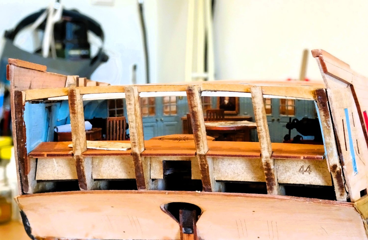
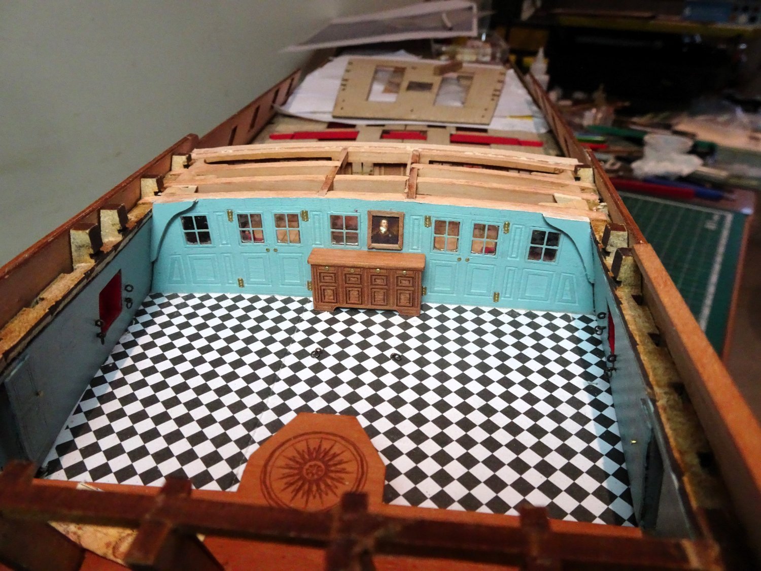
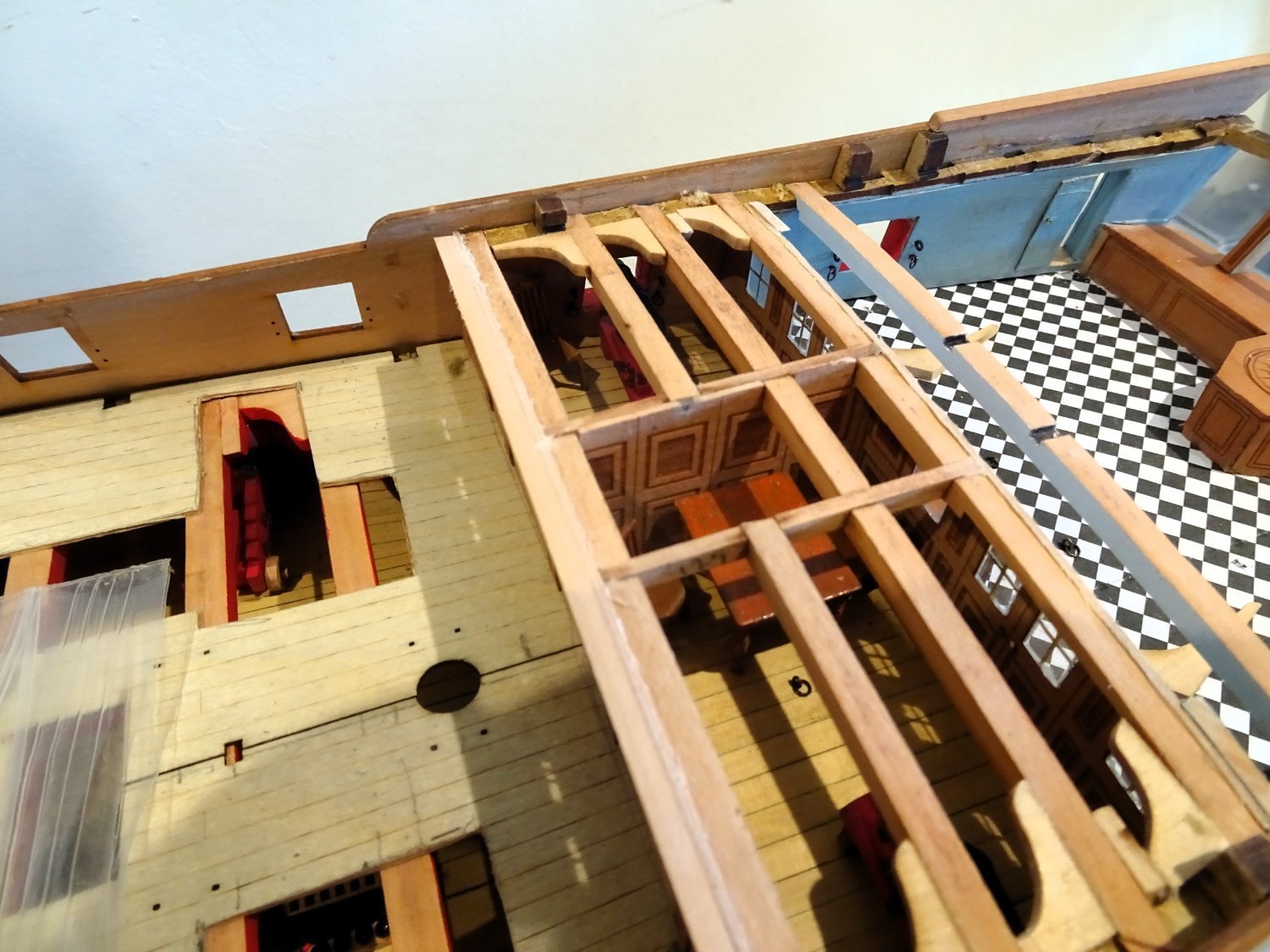
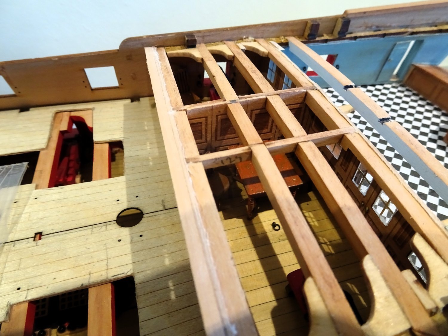
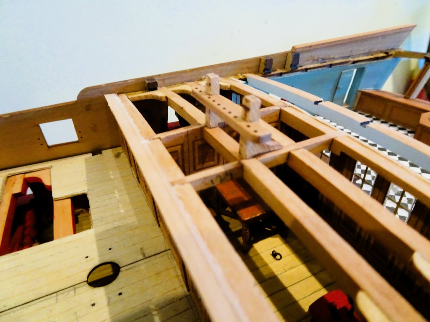
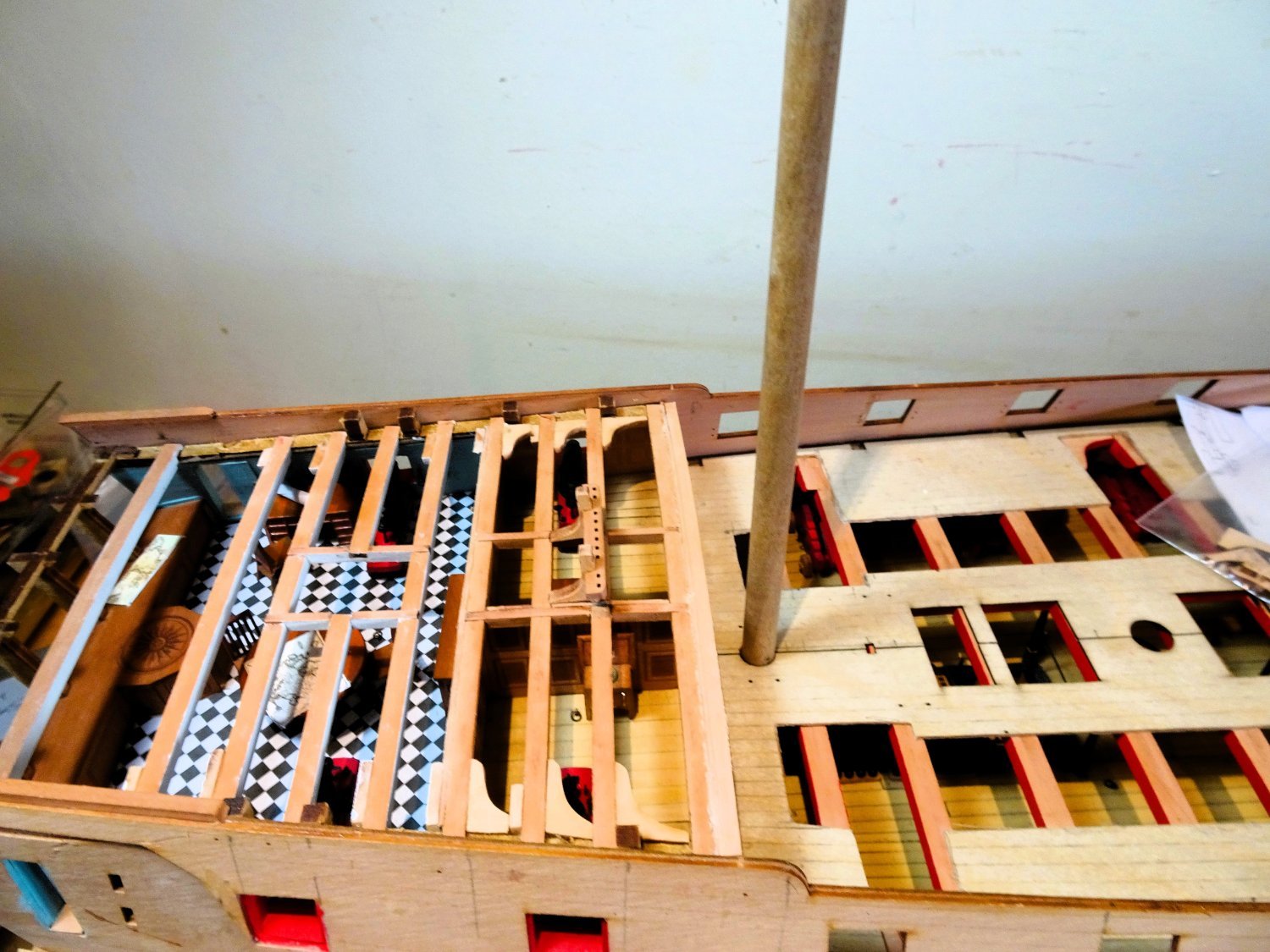
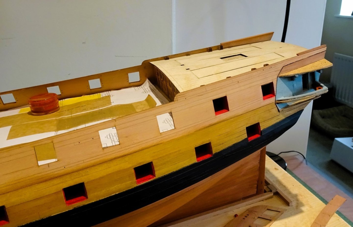
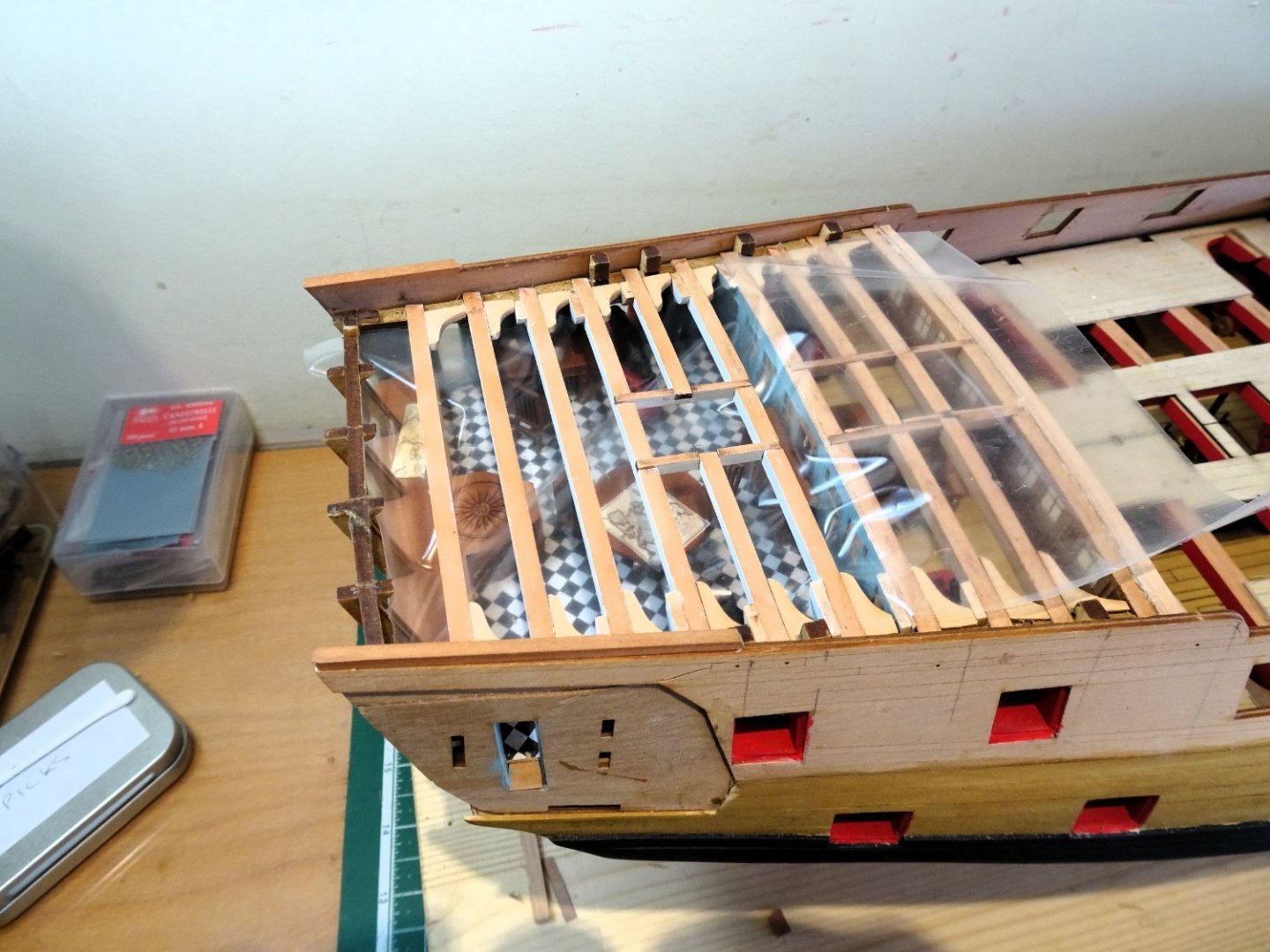
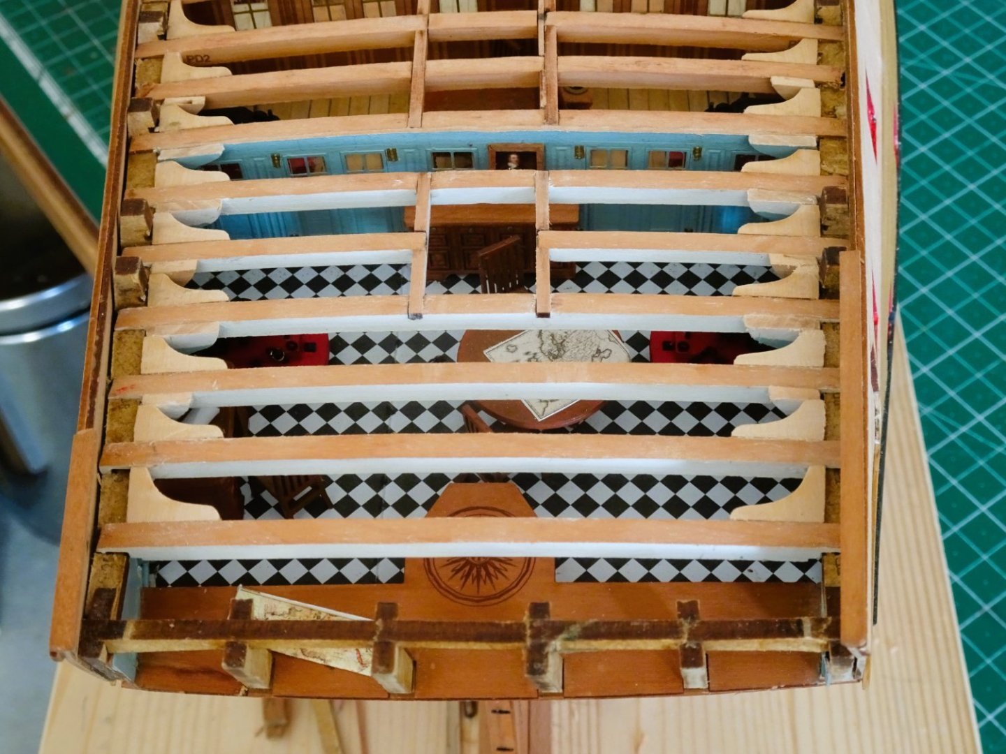
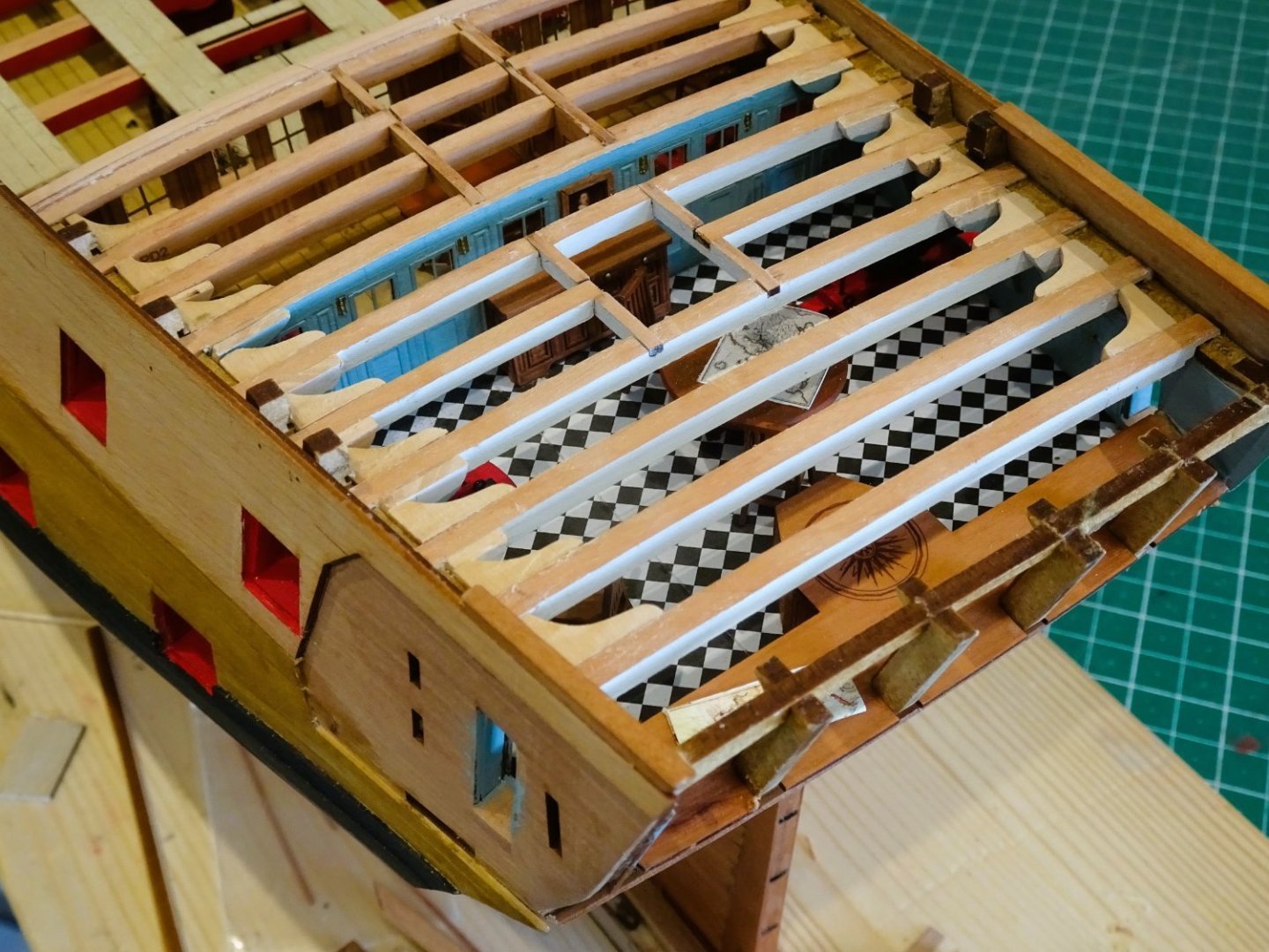
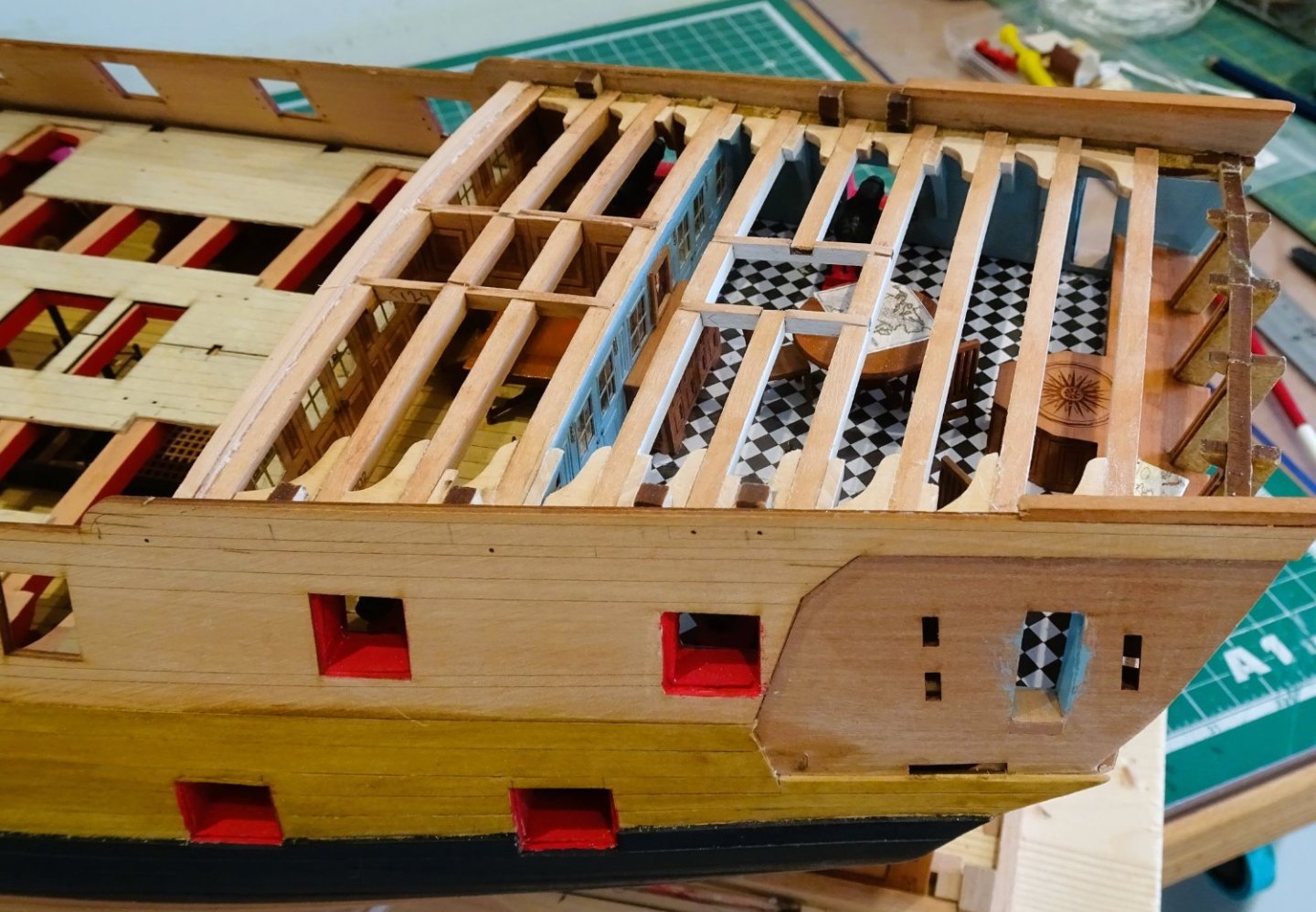
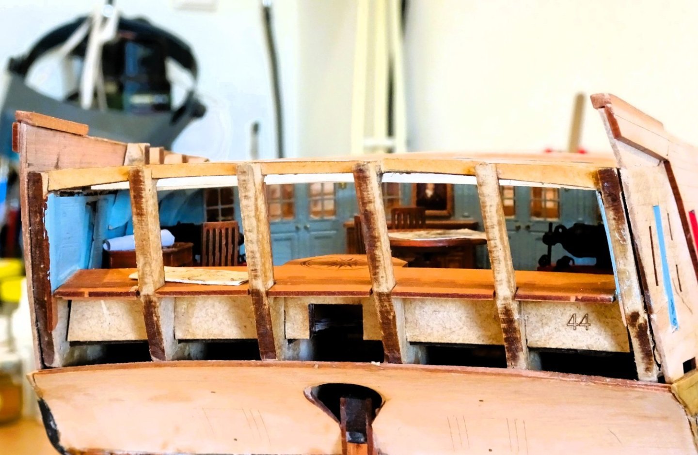
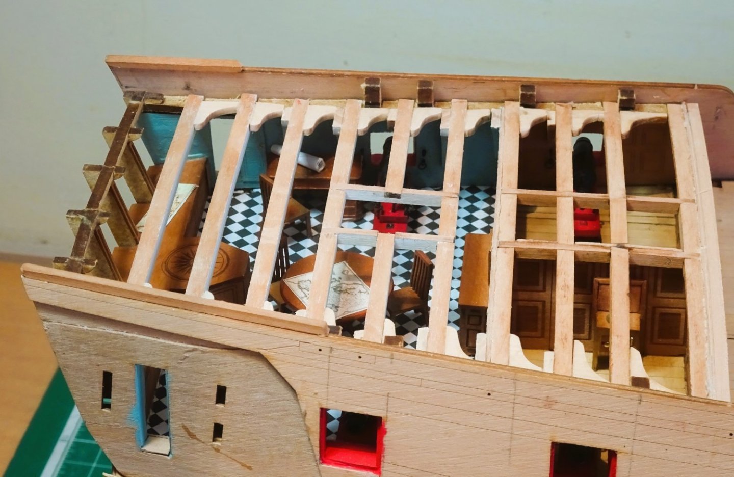
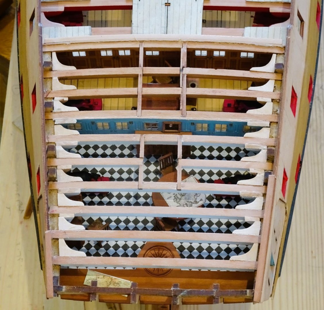
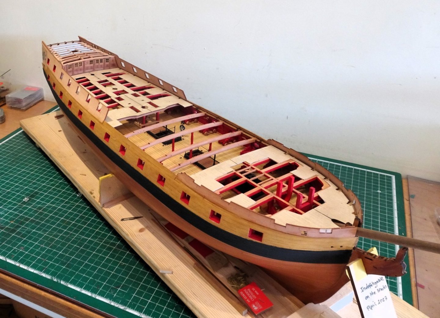
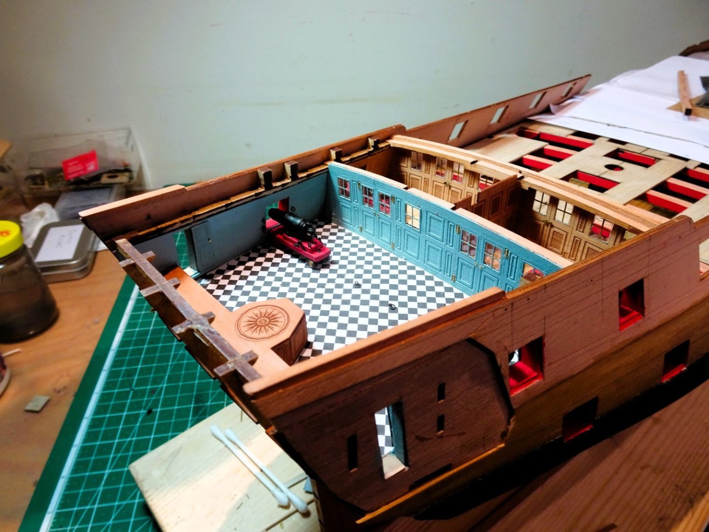
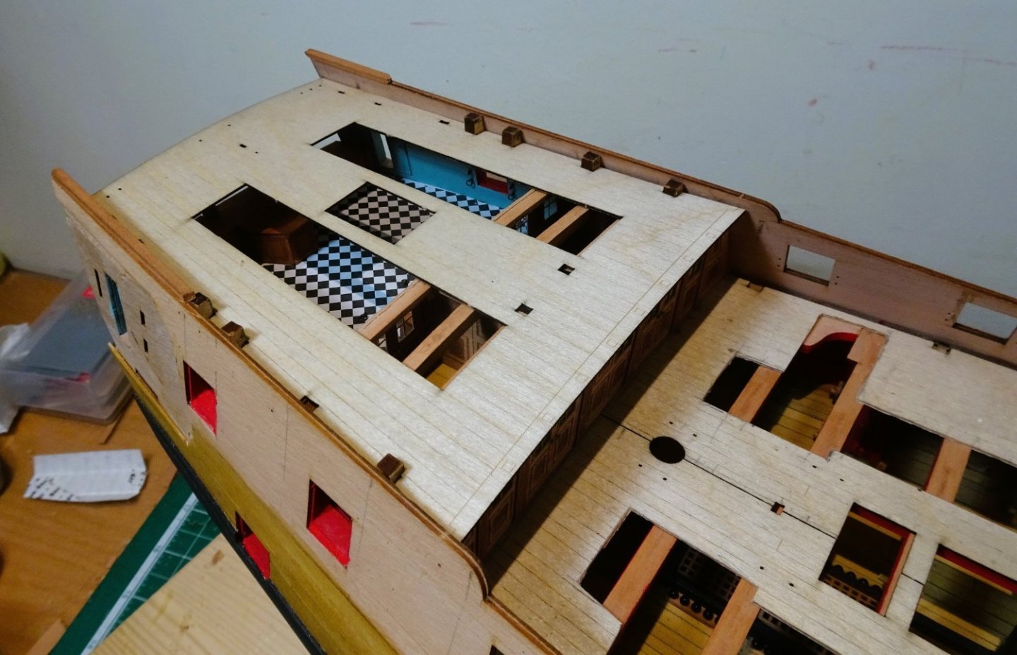
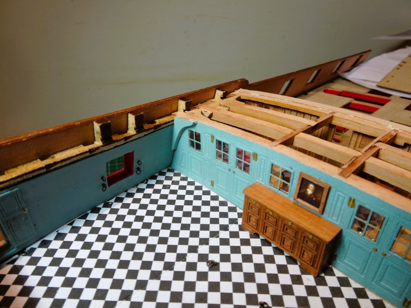
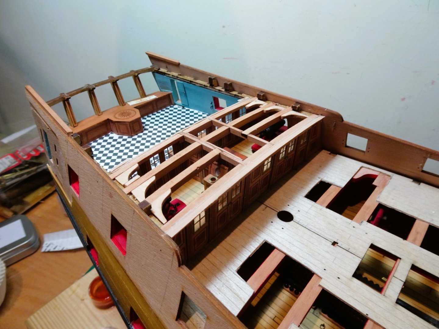
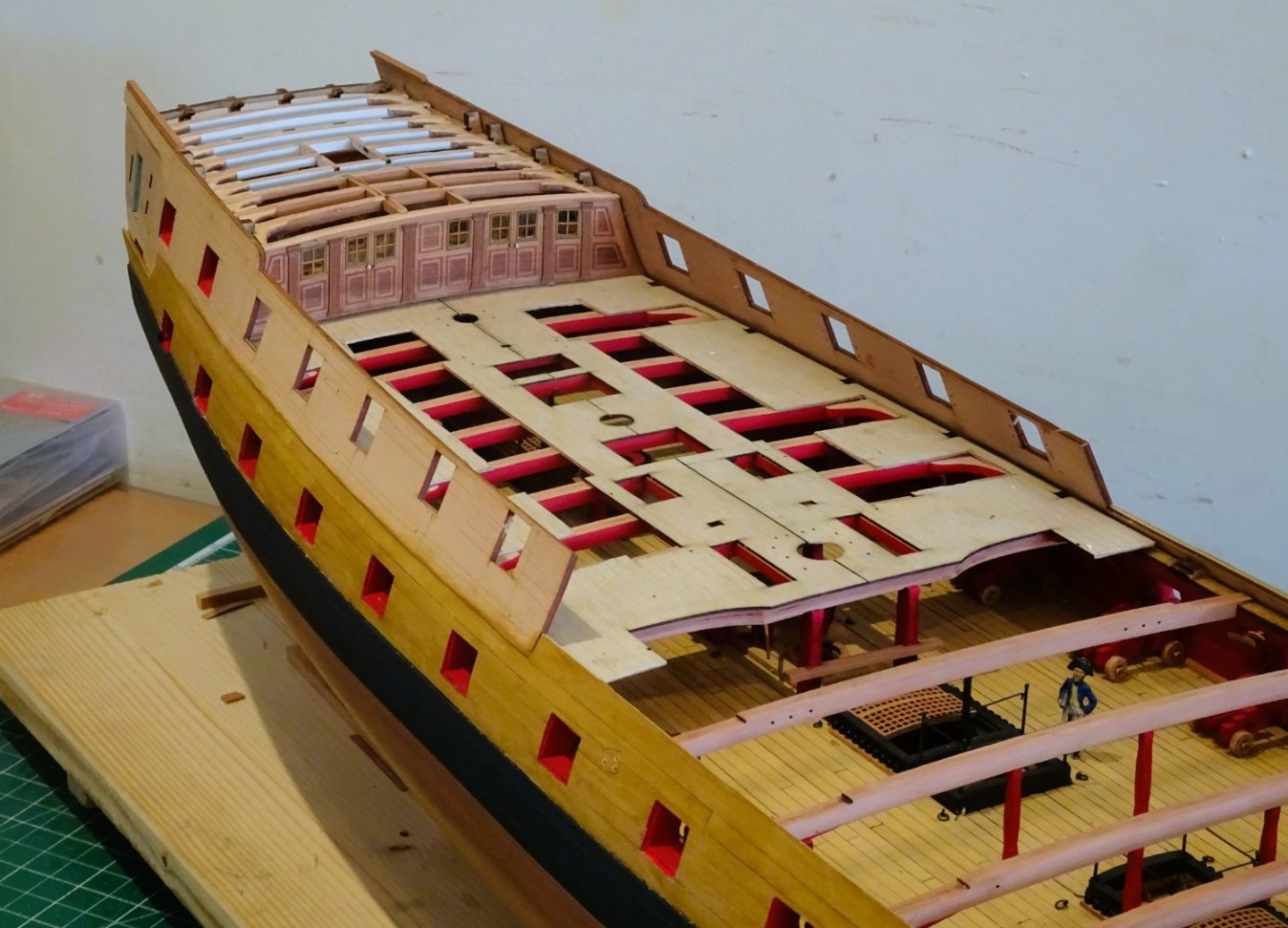
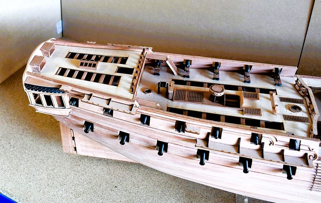
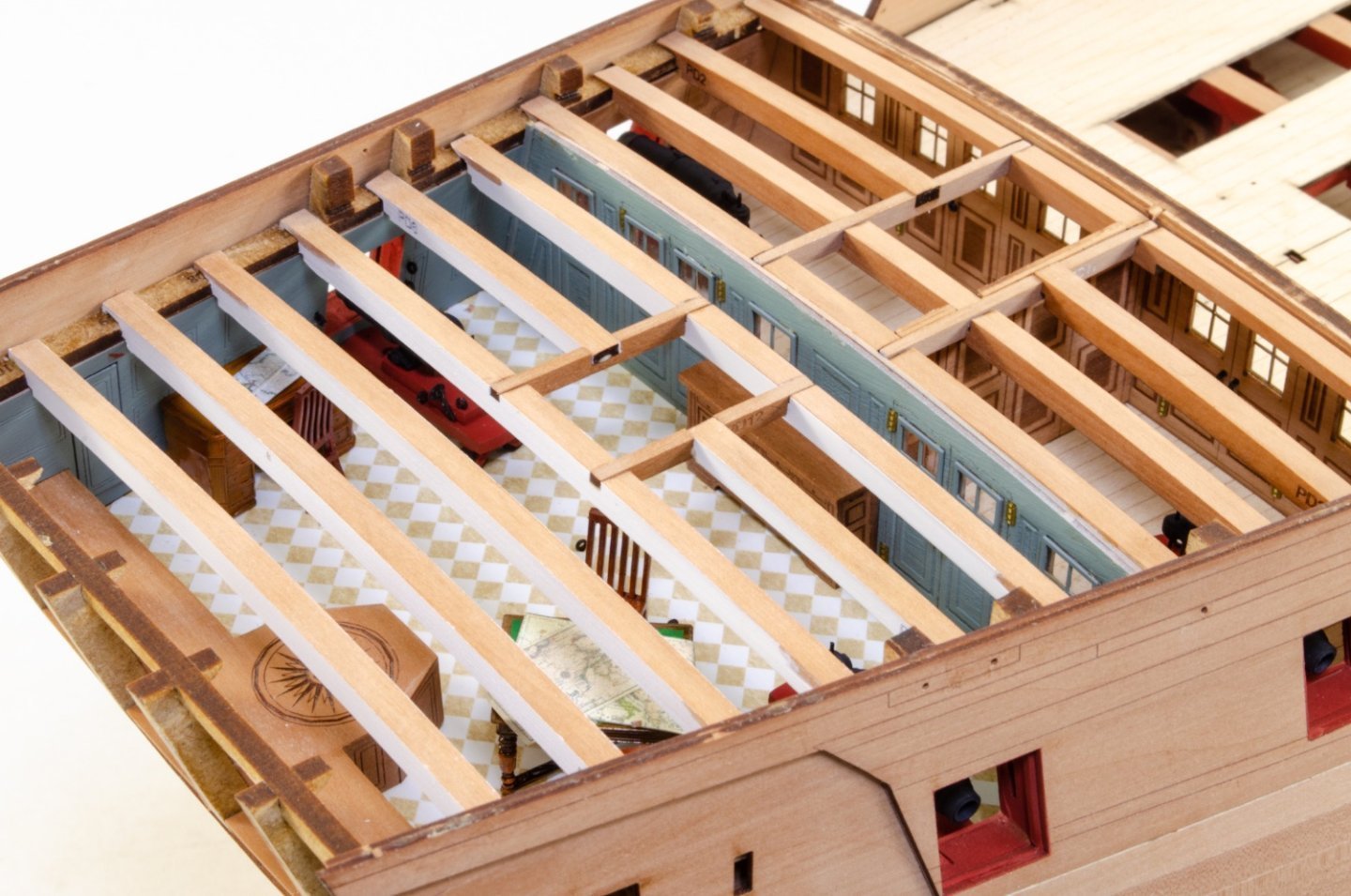
Post Ninety-three A peep into the Captain’s Quarters. The laser cutting of these parts is spot on and Chris has done a great job in providing the makings to allow us modellers to re-create realistic framing without many hours of work. 2363 I had some experience of making Lodging knees for my Sphinx build, and I’m so glad Chris thought to include them on ‘Indy’. 2365 The addition of scale cabin furniture is a nice touch and I’m very much pleased with the effect. 2366 I have no intention of hiding this detail, apart from the margins the Poop deck will remain unplanked. 2367 2371 2374 One of the main issues once the cabins have been completed is keeping dust out during further sanding and cleaning of the deck beams once the Lodging knees have been fitted. 2360 To this end I use some thin polythene threaded beneath the beams and over the fittings. The dust can be sucked off without the risk of dislodging any fittings. 2378 I’ll use the false deck to help keep dust out while I attend to the Stern/Qtr Galleries. B.E. 17/10/2023
- 648 replies
-
- 23
-
-

-
- Indefatigable
- Vanguard Models
- (and 1 more)
-
Cheers, Nipper, I get a feeling of great satisfaction that my log has helped others, part of what we're here for I think. B.E.
- 857 replies
-
- 3
-
-
- Sphinx
- Vanguard Models
- (and 1 more)
-
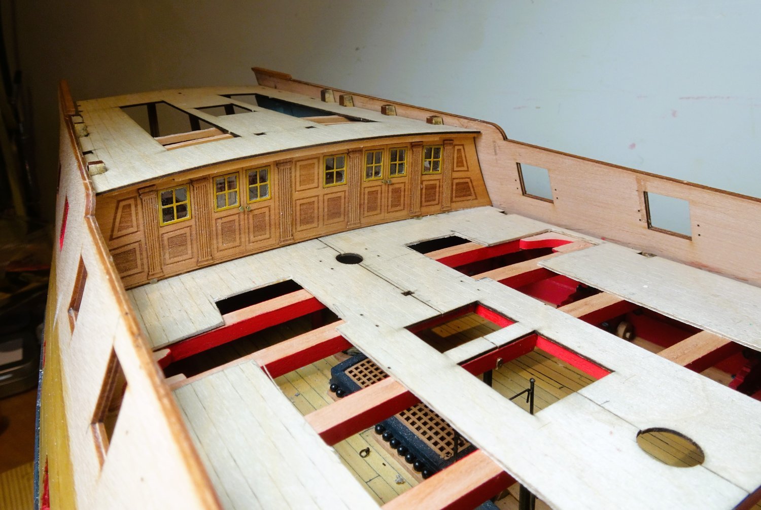
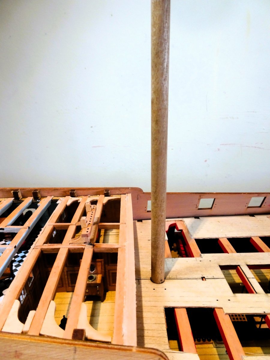
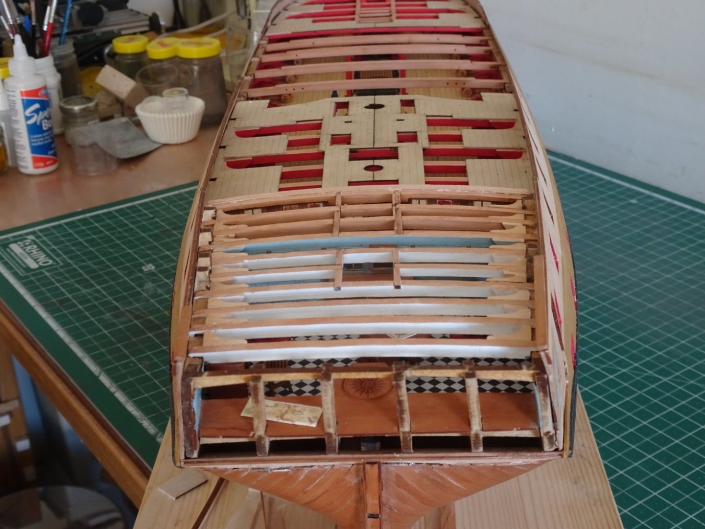
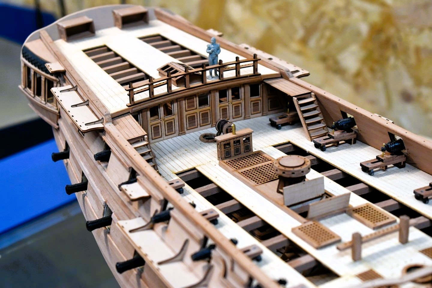
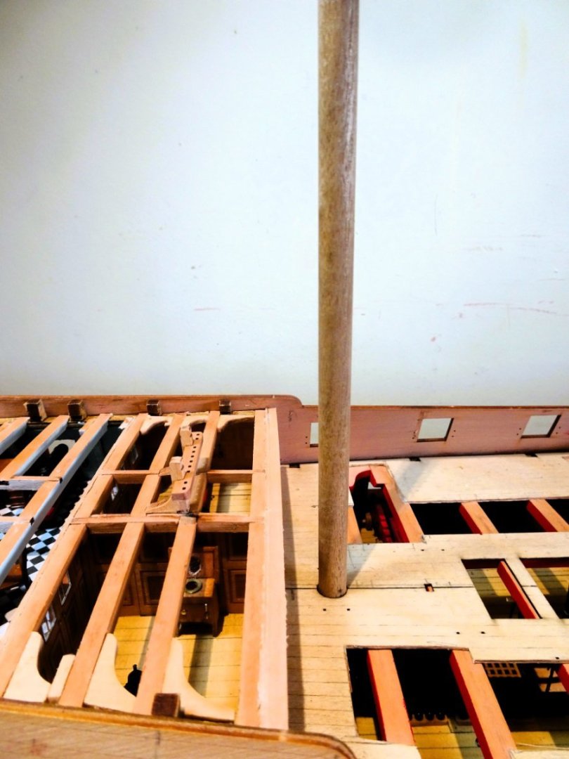
Post Ninety-two Poop deck beams Before I proceed, a small problem to sort. 2300 As can be seen in the above photo the forward screen sits around 1mm above the first Poop deck beam(PD1) This looks the same as the manual photos but doesn’t allow the Poop sub-deck to sit down flush across all the beams. I had initially wondered whether the deck would run flush to meet this ‘rebate’ but decided to sand it flush with the deck beam which allows proper seating of the deck. 2331 2332 I am pleased to note that the Poop sub-deck slips seamlessly into place without any adjustment. There will be much less of it when I get to that stage. Forward cabins The beams have few considerations as there are no full hanging knees to work around the cabin fittings. 2340 The beams and knees fitted into place with the minimum of fuss. The Great cabin This is a different story as there are three sets of full hanging knees to fit, plus two sets of short versions. It takes some careful thought to work out the sequence of beam fitting to give the best access for the long knees without the risk of dislodging any previously fitted furniture, but I found I could progress furniture adding as I moved along. There is scant information in the manual regarding the fitting of knees other than to refer to the plan (Plan sheet 5) For what it’s worth this is the sequence I adopted. The first long hanging knees fit against the screen on the inner side. 2335 These are easy to fit as it is done before any beams are installed. I found it necessary to reduce the height of the knee along the top edge by 2mm to bring it clear of the window frames. 2334 Once fitted they are painted to match the bulwarks. At this point only the sideboard has been fixed into place. The remaining beams of the Great cabin roof are now painted white. 2346 Beam PD5 can now be fitted followed by the second set of long knees which are again painted insitu. The guns are now added, followed by Beam PD7, followed by the last set of long knees. Access is still good to position these. At this point the remainder of the furniture is added to the deck. In my case the rather elegant pedestal table, desk, and chairs. Beam PD8 is now added together with short version knees. Beams PD9&10 follow, no hanging knees involved. Finally Beams PD6 and carlings are put into place, these form the support for the Skylight. Short knees are attached to beam 6 but they need to be trimmed to keep them clear of the gunport. They are necessary to provide spacers for the Lodging knees. 2362 2373 The final action is to add the Lodging knees. 2379 So, the fitting out is complete and it proved less frustrating than I had first imagined. I will post some photos of ‘what lies beneath’ in the next post. B.E. 16/10/2023


- 648 replies
-
- 17
-
-
- Indefatigable
- Vanguard Models
- (and 1 more)
-
Thank you Ron, The practicality of the Bitts position will only really become apparent when the rigging starts. The kit shows only the Mizen Topsail/T’gallant sheets , Boom Topping lifts, and Main Topsail yd braces belaying at the Mizen Bitts. The sheet lines catch my eye; these as you know feed thro’ the sheet blocks beneath the yards close to the cleats and belay where else, but the Mizen Topsail sheet Bitts. The lines are usually run more or less vertically from the sheave to belay. With the Indy set up they are required to angle aft to belay. As a full sail man you would be involved with a lot more lines belaying at the bitts, Reef tackles, and halyards come to mind. This is all academic to me with stump masts only so time I moved on. ps; This is the first time I’ve looked the rigging plans, and I have to say Chris has done a fine job, beautifully drawn.👍 B.E.
- 648 replies
-
- 4
-
-
- Indefatigable
- Vanguard Models
- (and 1 more)
-
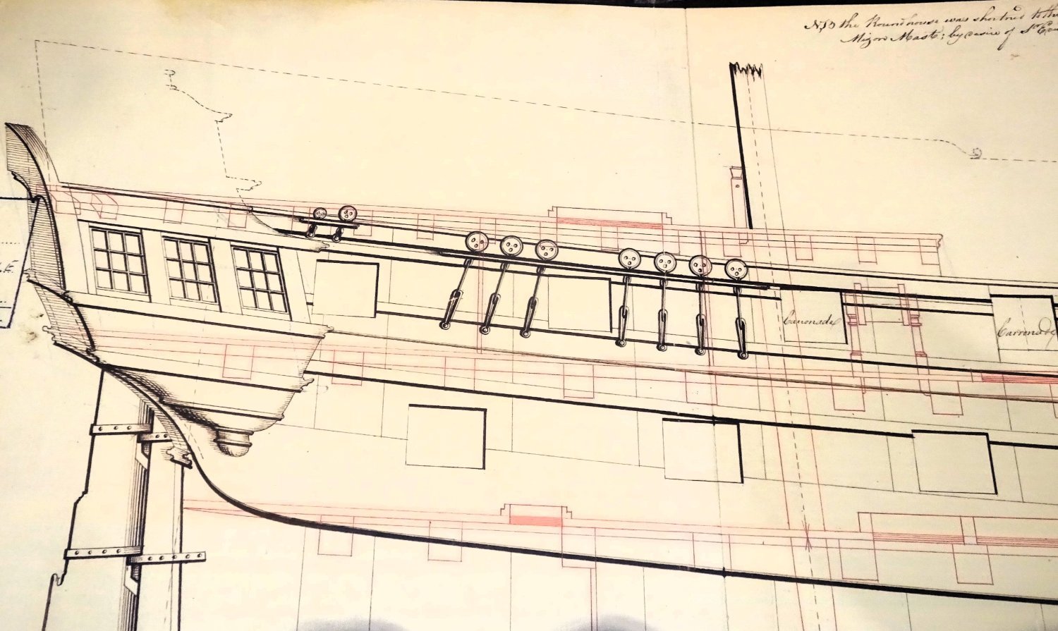
Thanks for looking in Gary, I love that model of Victory, but the arrangement lasted but a few years around the mid 18thc. Victory 1765 The Poop on Victory is similar to how the Poop would have looked on Indy when razeed, but before it was further reduced in depth at the request of Pellew. The official plan only shows the original modification but notes that the request was made and actioned. 2358 You can see from the plan a bitt pin very close behind the Mizen mast and the Skylight, or maybe a hatchway close behind it. On the kit interpretation the Mizen bitts are some 8’ from the mast, which is a long way from the usual arrangement It can be seen that the poop extends beyond the third port and gives some cover to the helmsman. How it was actually configured we shall probably never know, so it’s down to educated guesswork, and I’m still troubled by the position of those bitts. The simplest option for me is to leave them off, that way I won’t continually look at the model and think- should they really be there. Ps I must get back up to Hartlepool, been a few years since I last visited Trincomalee. B.E

- 648 replies
-
- 2
-
-
- Indefatigable
- Vanguard Models
- (and 1 more)
-
Thank you Thuky, Writing this stuff helps me sort my own thoughts, and provides a record of why I did things. In the past I have been asked why did you do that, and I was damned if I could remember.🙄 It also provides me with a break from actual building, and I simply enjoy it. I'm glad you find it helpful. Cheers, B.E.
- 648 replies
-
- 5
-
-
- Indefatigable
- Vanguard Models
- (and 1 more)
-
The skylight in it’s original position did look odd, and much better moved to over the Great cabin. Had the Poop deck remained as originally designed to incorporate the Mizen then the bitts on the Poop deck would have been in order. With Pellew’s request to shorten the poop, leaving the Mizen exposed on the Qtr deck, Mizen bitts on the poop make no sense, they are badly positioned for belaying many of the lines that directly lead down the mast. The one thing common to Bitts is that they are close to the mast. Could there not have been a mast ring on the Mizen, there looks to be room. At this point I have not looked at the kit rigging plans to see where lines such as the clews, lifts, and bunts are belayed as I am not masting and rigging her. It is a tricky business trying to interpret what may have been, but for me it just feels wrong in this instance. I acknowledge the effort and thought you put into the design of these models Chris, I too agonise over details, and we all hope to get things as good as they can be. Always more questions than answers. B.E. exposed on the upper deck
- 648 replies
-
- 4
-
-
- Indefatigable
- Vanguard Models
- (and 1 more)
-
Post Ninety-one Ponderings about the Poop In the early days of development of Indy Chris made a few modifications in this area. development photo Forgot to mention, I have moved the poop skylight back by 3 beams, as I realised it was too close the edge of the poop, so it is now over the great cabin, and not in the position shown. development photo As I moved the skylight back so that it is now over the great cabin, I saw no reason not to add mizzen bitts and belaying cross rail. Sensible modifications based on a practical approach in the absence of any original information. The official Indy plan (ZAZ2371) shows the skylight in its original position, and I cannot find a plan of the modified razeed Indy’s Poop deck framing. We 20th century people have no idea whether Pellew may have preferred the light over the coach, rather than the better lit Great cabin, but aesthetically it certainly looks a lot better. We do know that he wasn’t even very keen on the poop deck arrangement at all, but the Navy Board did not accede to his wishes. 2348 In framing the Poop deck Chris has left the timber arrangement of beams and carlings for the original position of the skylight before Indy was razeed. For an oob build this has no relevance at all, but for my hoped-for arrangement it impacts on the Mizen Bitt placement should I choose to fit them. I had in mind to place the Bitt pins atop the beams and leave that area unplanked, but under the present set-up there is no convenient beam to support the bitts. In reality Mizen Bitts would be set into and bolted to the adjacent deck beams. 2352 One thing that bothers me about the placement of the Mizen Bitts is the distance from the Mizen mast. Most of the lines of the mast, the lifts, clews, and the like, come down thro’ the tops and belay close to the mast, often on a mast ring, even on large Frigates. Maybe Chris’s original idea of racks incorporated either side of the Poop breast rail would work better, they would certainly be closer to the mast. Even so, the bitts are a nice feature and should I choose to fit them I have two options; Maintain the decking in that area, which would hide much of the Bedspace/Coach; which I don’t really want. Or; 2349 Fit a ‘false’ beam (as above) between the carlings above the coach to support the bitts, plus carlings as necessary. 2350 I think I can tweak the position of the bitts by a couple of mm or so either way. 2353 Not decided which way to go, but I’ve some time before the need arises. B.E. 14/10/2023


- 648 replies
-
- 15
-
-
- Indefatigable
- Vanguard Models
- (and 1 more)
-
Thanks Jim, As you can see from your photo above, the screen rises around 1mm above the beam; decision made, I'll sand it flush. B.E.
- 488 replies
-
- 4
-
-
- Indefatigable
- Vanguard Models
- (and 1 more)
-
Sorry you've had a poor end to your hols Chris, especially as it was your first break in eight years. It's obviously dangerous to be out of your workshop, Have you checked whether it's Covid or flu, but either way I hope you are back firing on all four pdq Cheers, B.E.
-
Hi Jim, Sorry to bother you, I have a small puzzlement about the Poop deck beams. Section 418 shows part PDO attached flush with the top of the forward screen, no issue. 461 When the first Poop deck beam PD1 is fitted the screen sits above the beam level as seen on the manual photos in section 454 and as it does on my build. At the time of fitting I thought the deck pattern would run up to the screen level making the area flush, so thought no more about it. However, the Poop sub-deck runs across the screen top, so I thought I would check whether you sanded the top of the forward screen level with the first beam or just fitted the Poop sub-deck over it as is. My feeling is it should be flush, but I didn't want to sand it and then find there is some subtle reason why the screen stands proud. Regards, B.E.
- 488 replies
-
- 5
-
-
- Indefatigable
- Vanguard Models
- (and 1 more)