.JPG.ca33079f5815b861e67b9c2cccd37982.JPG)

Blue Ensign
-
Posts
4,564 -
Joined
-
Last visited
Content Type
Profiles
Forums
Gallery
Events
Everything posted by Blue Ensign
-
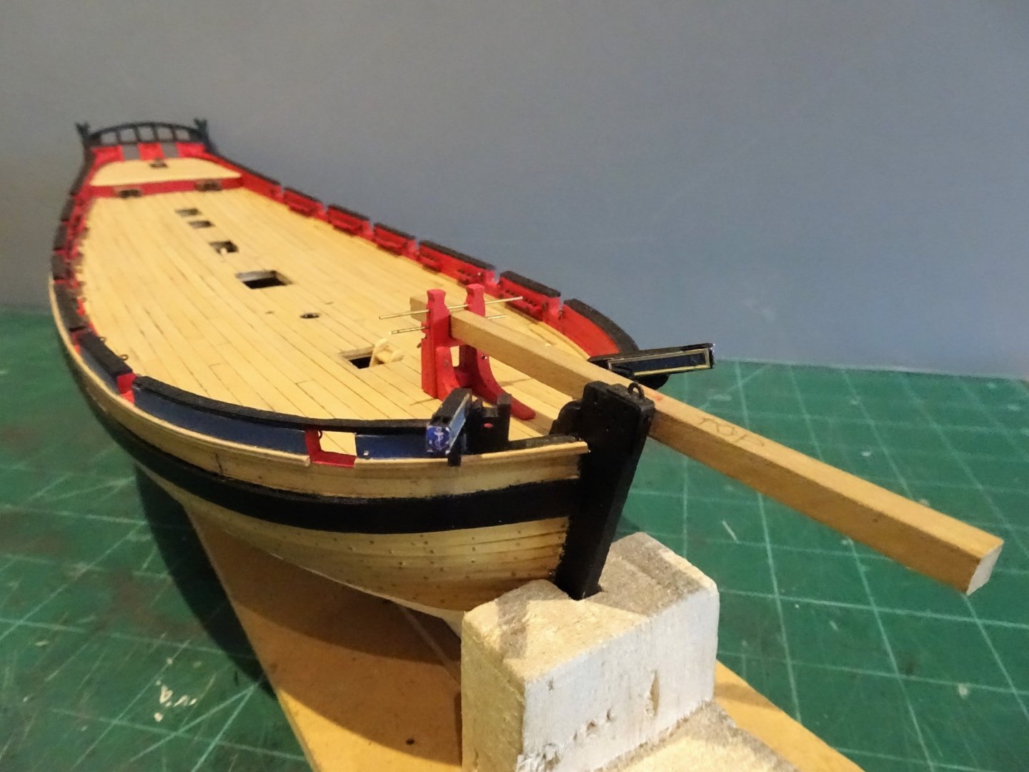
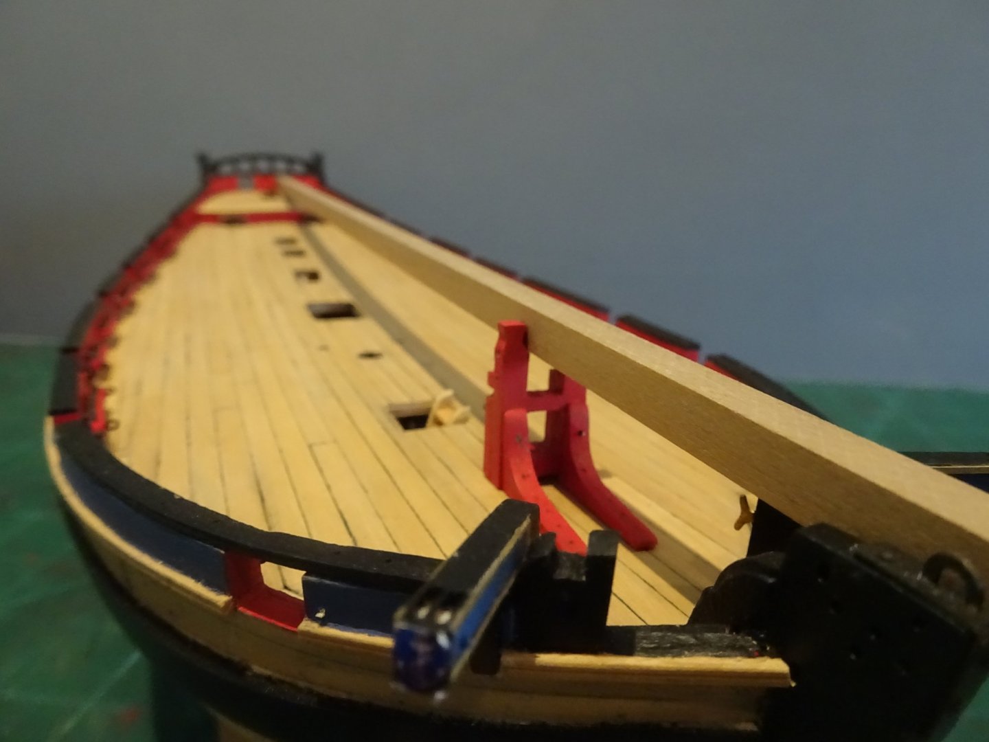
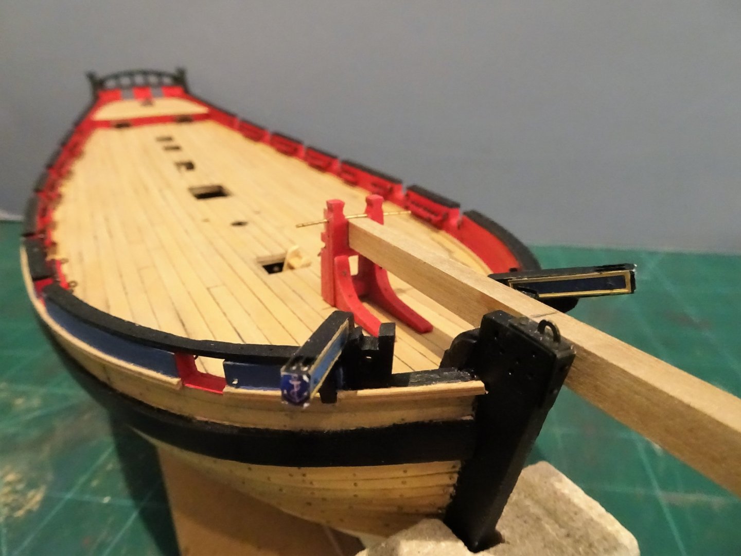
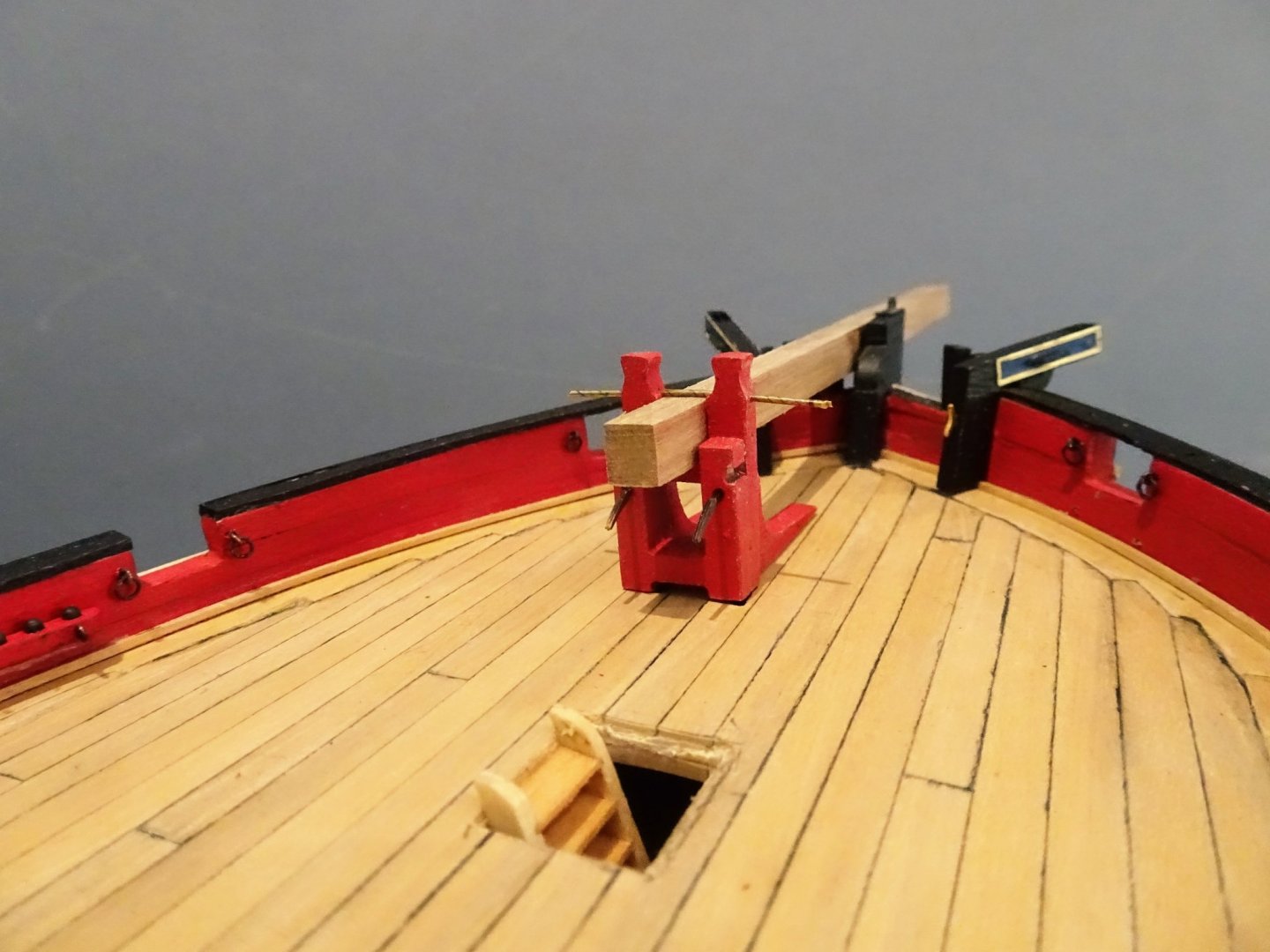
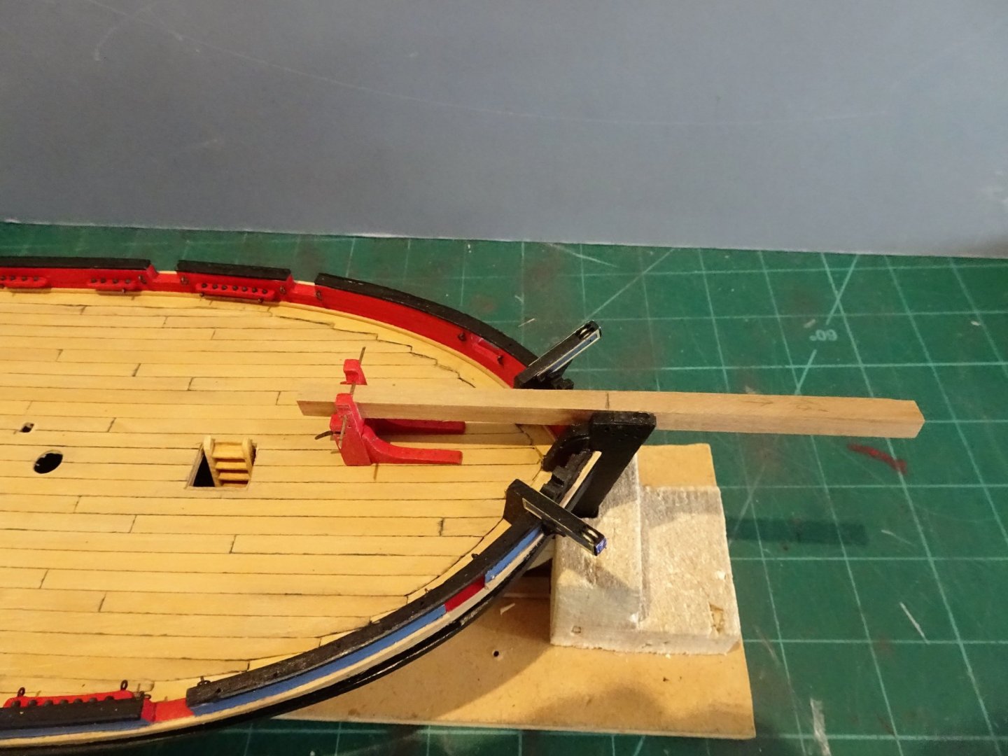
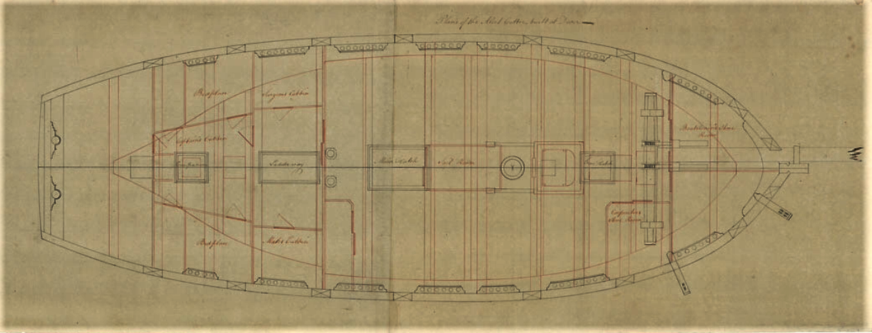
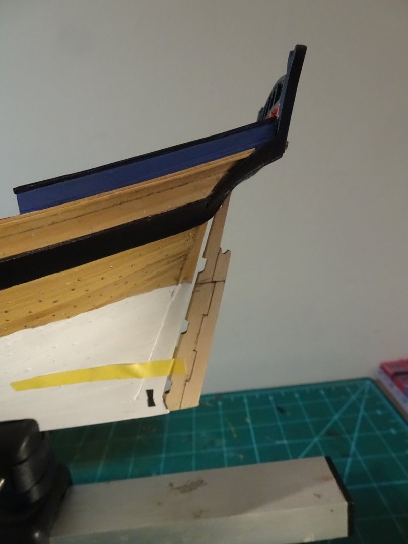
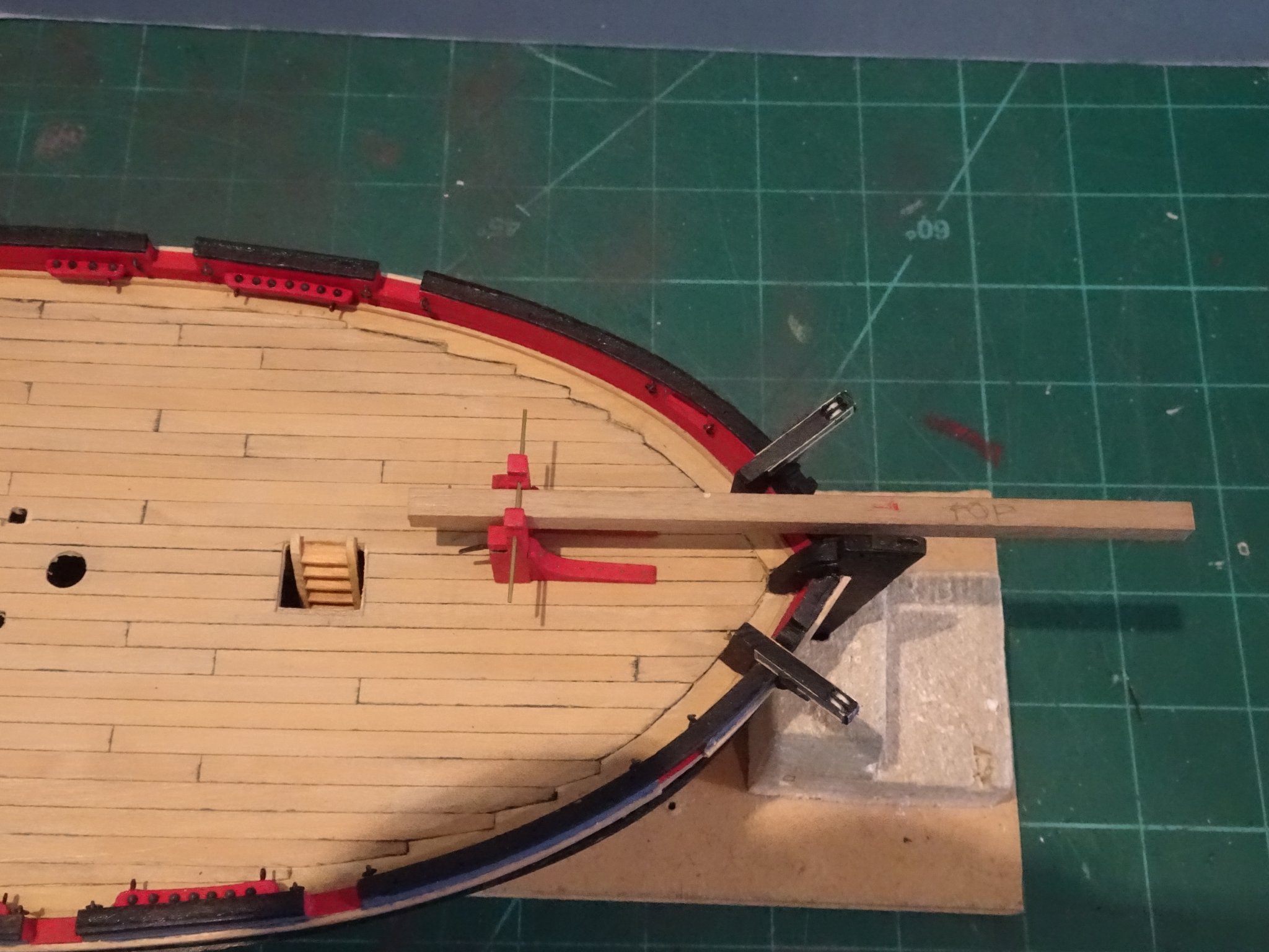
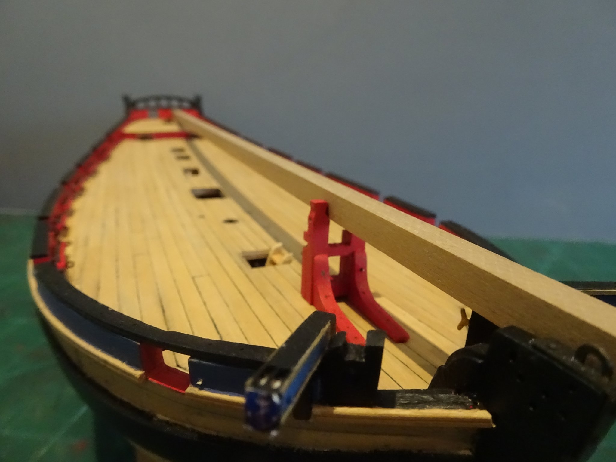
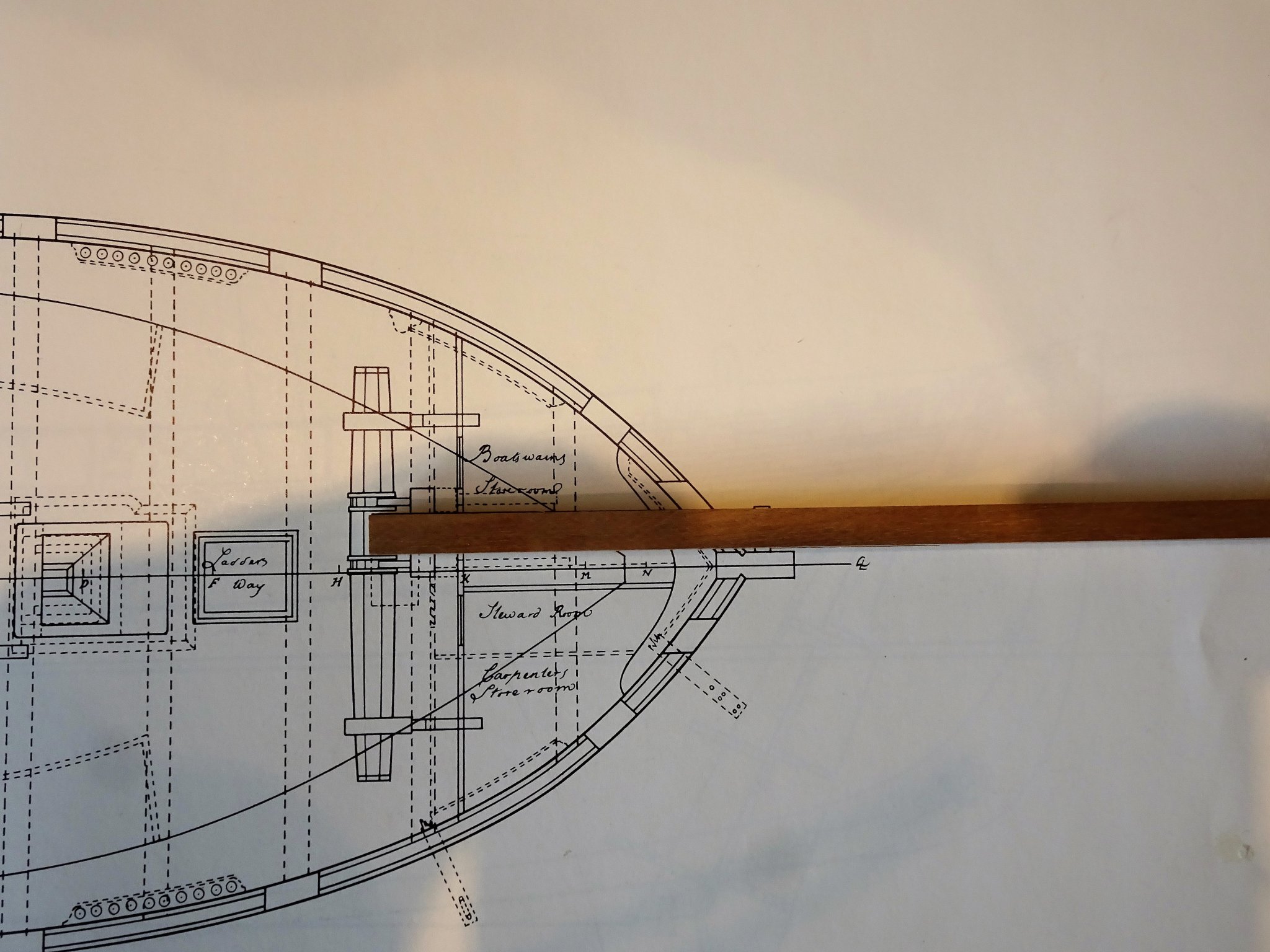
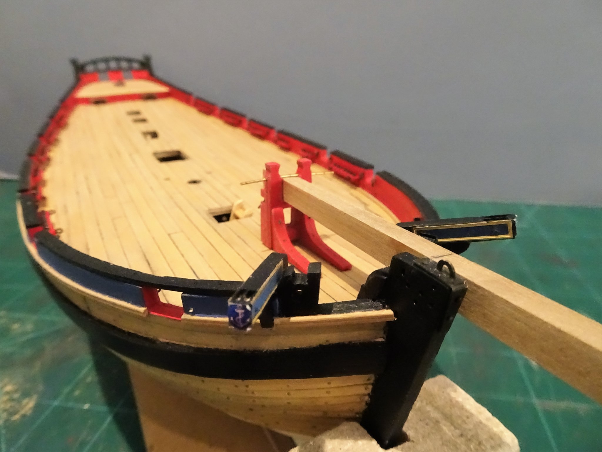
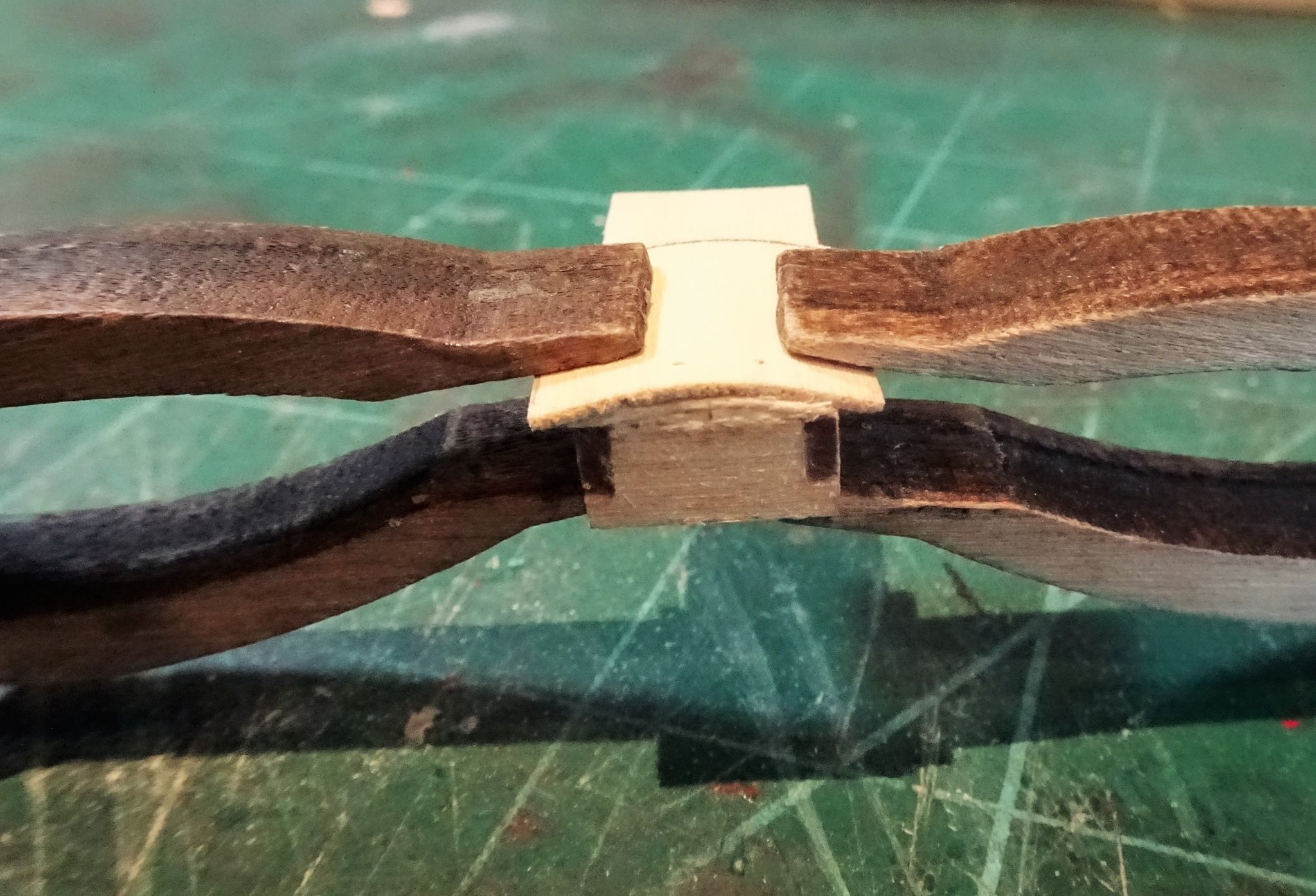
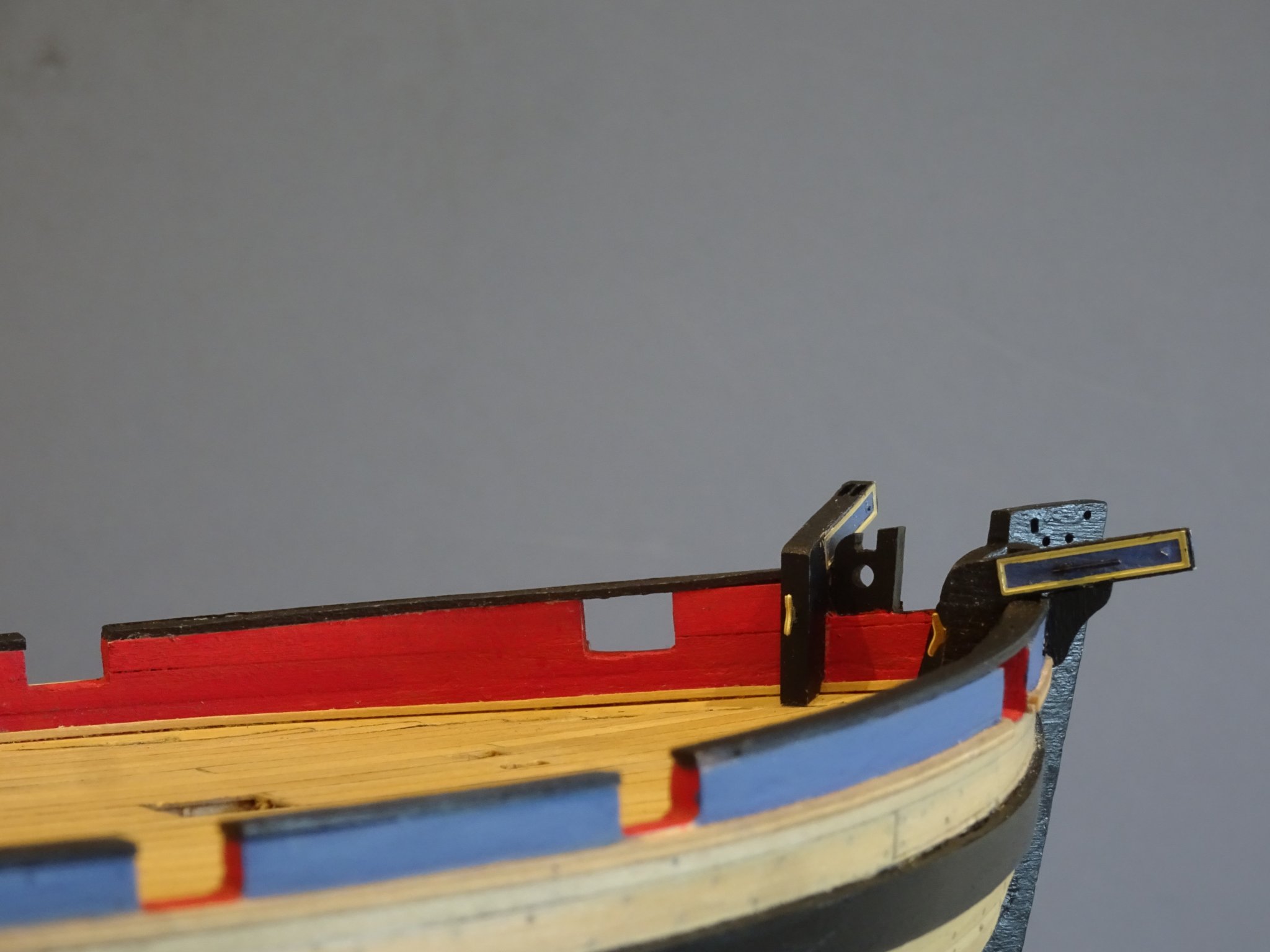
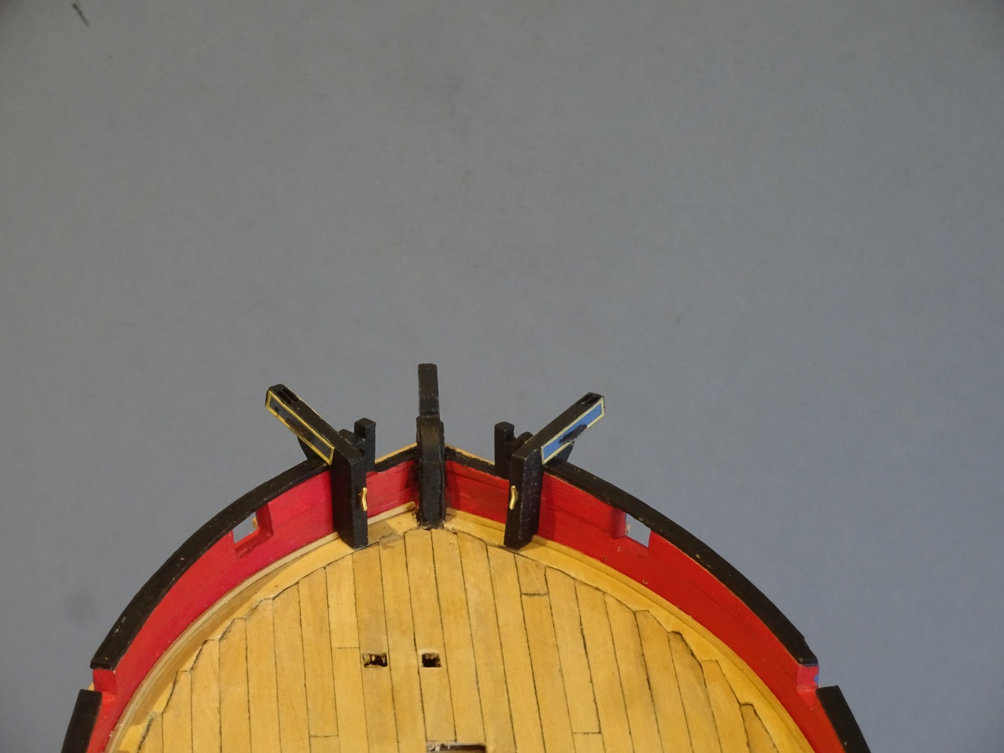
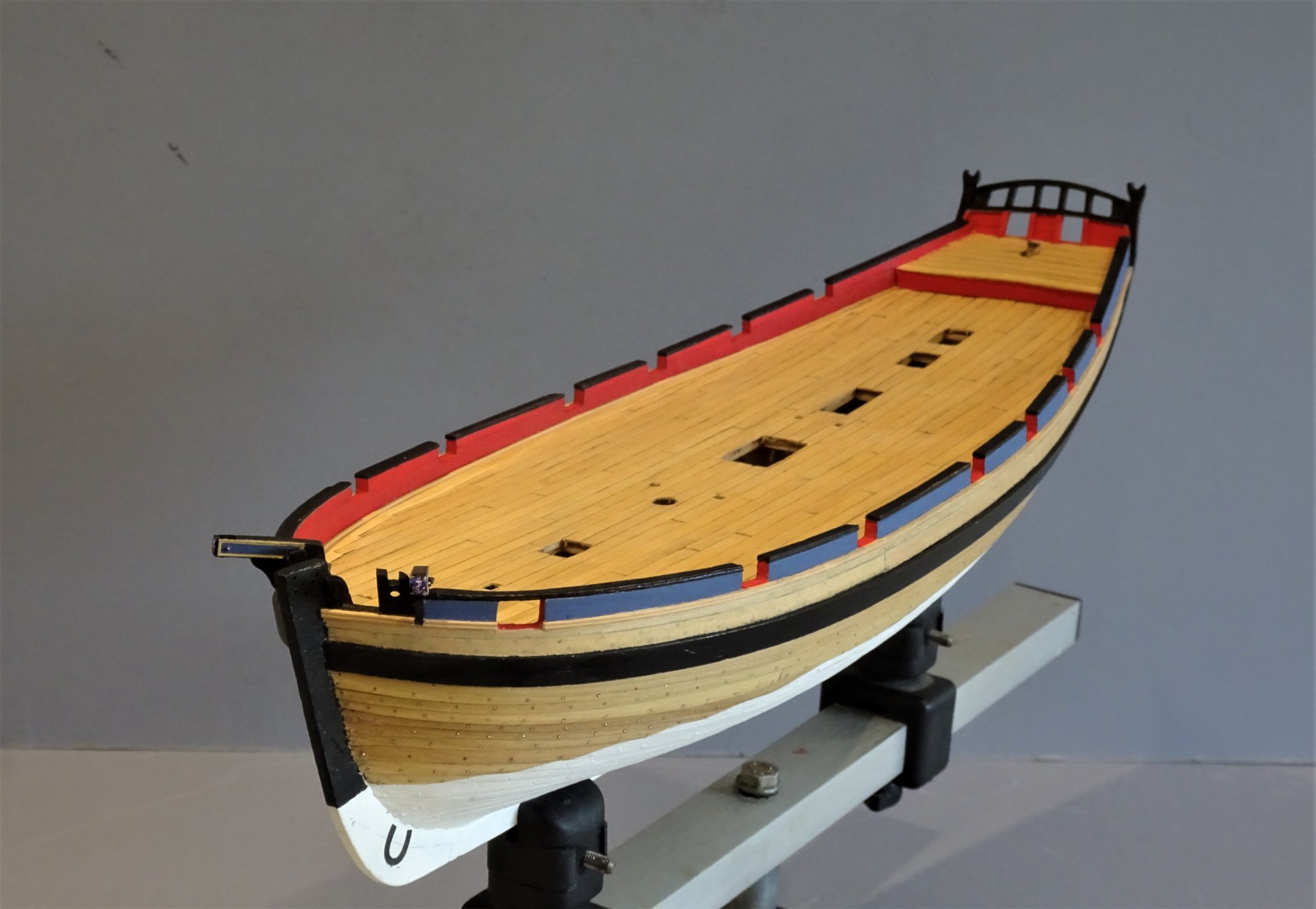
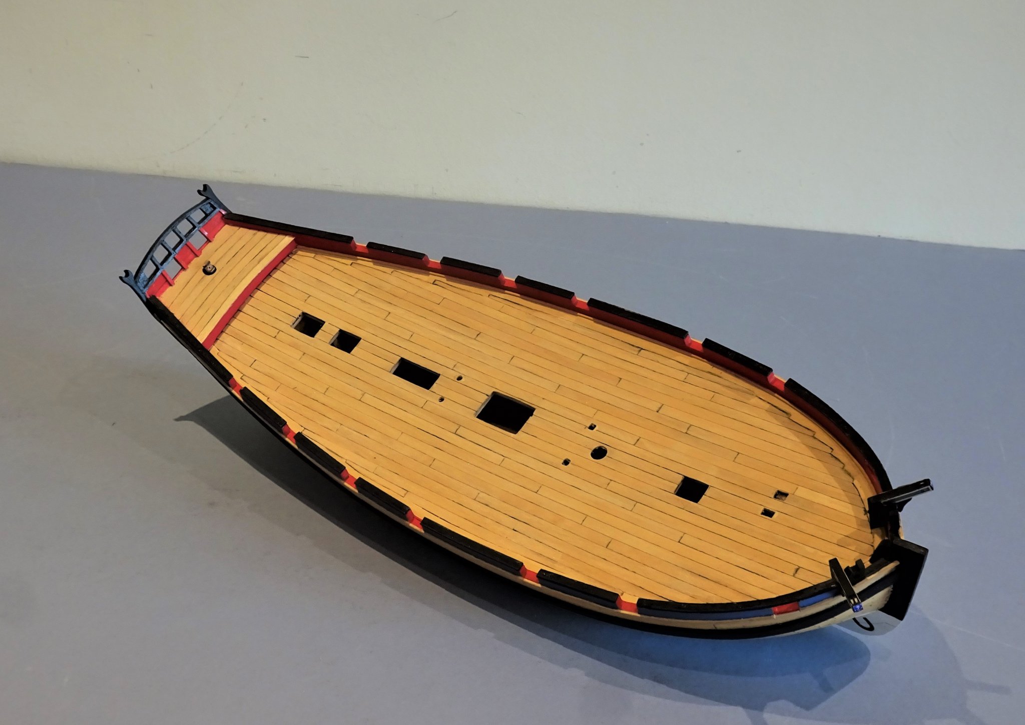
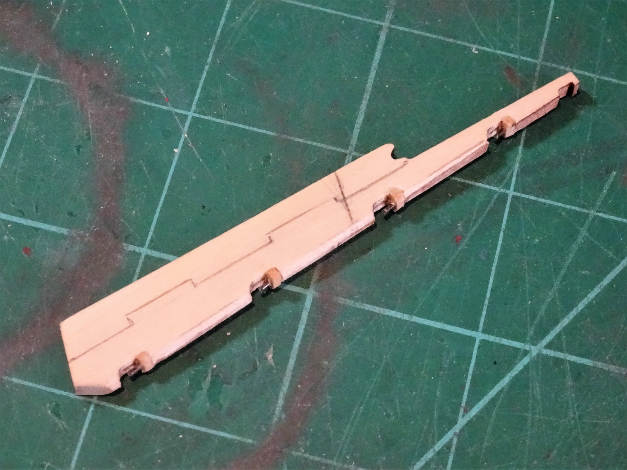
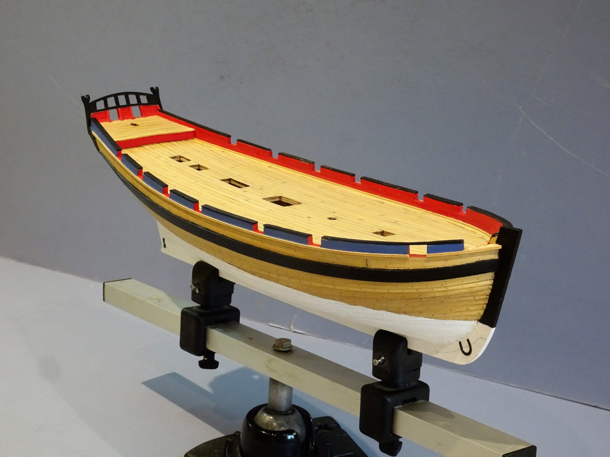
 Cheers Guys, now a bit of a set back. Post 33 Pawl Bitt pins (Bowsprit Step) I have been working on the Bowsprit Step but have hit a problem regarding the dimensions of the Bowsprit which I need to resolve before I can move on. You can’t really consider the Bowsprit Step without looking at the fit of the Bowsprit. There is a simplification on the kit part in that the iron fids used to fix and retain the Bowsprit heel are represented by solid wood top and bottom, formed by the square cut-out for the Bowsprit heel. There is a fid hole and fid indicated in the Bowsprit but this sits forward of the Bitt pins, which makes little sense. 3410(2) I removed the top bar and drilled thro’ to take the ‘iron’ fid. A hole below this was drilled to take the retaining fid for the Bowsprit heel which has a corresponding hole drilled. The inboard squared end of the Bowsprit is shown as 6mm, reduced and squared from some 8mm ø dowel. My own preference is to use square stock, and round the outboard section on the lathe. Now I come to the problem: 6mm square stock will not fit between the step uprights whereas 5mm as shown in the above photo is a good fit. However, the dimensions given in the Alert Book are 18½” which equates to 7.3mm at scale, whereas 6mm is a perfect fit for the Alert book drawings. 3429 6mm stock laid over Alert book drawing at 1:64 scale Note: The Alert book quotes dimensions as relating to the cutter Pheasant which was slightly shorter than Alert and some 34 tons lighter. Her Bowsprit is given as 56’6” L x 18½” ø Pheasant capsized in the Channel in 1781, perhaps she was over sparred. When in doubt I always refer to Steel; For a 200-ton cutter (Alert was 183 tons) Steel gives a Bowsprit length of 64’ (304.8mm) with a 20” ø (7.93mm) By comparison the kit dimensions are a scale 275mm in length and 6mm at the heel (57¾’ and 15” diameter). 3418 3420 3422 The photo’s above show the 5mm square stock in place. Below I compare 6mm square stock. 3428 Without either thinning down the uprights or the 6mm stuff it just won’t fit. I am reluctant to thin down the bitts which look good for scale. However, the evidence of Steel is that the Bowsprit may have been even longer and certainly heavier at the heel. To thin down the 6mm stuff so it fits between the uprights, but leaving the depth the same, effectively makes it a rectangle rather than a square. 3432 Thinned down 6mm stuff to fit between the uprights 3433 3431 I can’t clearly see from the instruction photo’s what Chris did on the prototype to get the fit, whether he modified the mortise or reduced the heel or a combination of both. I can’t settle my mind on how to proceed so I have decided to make a Bowsprit using 6mm square stock using the taper formula given in Steel, the heel will then be reduced to fit between the bitts. I will then let my eye be the judge. B.E 08/11/2019
.thumb.JPG.d14b850c518ed76dd9d76efc52495d00.JPG)


- 335 replies
-
- 9
-

-
- alert
- vanguard models
- (and 1 more)
-
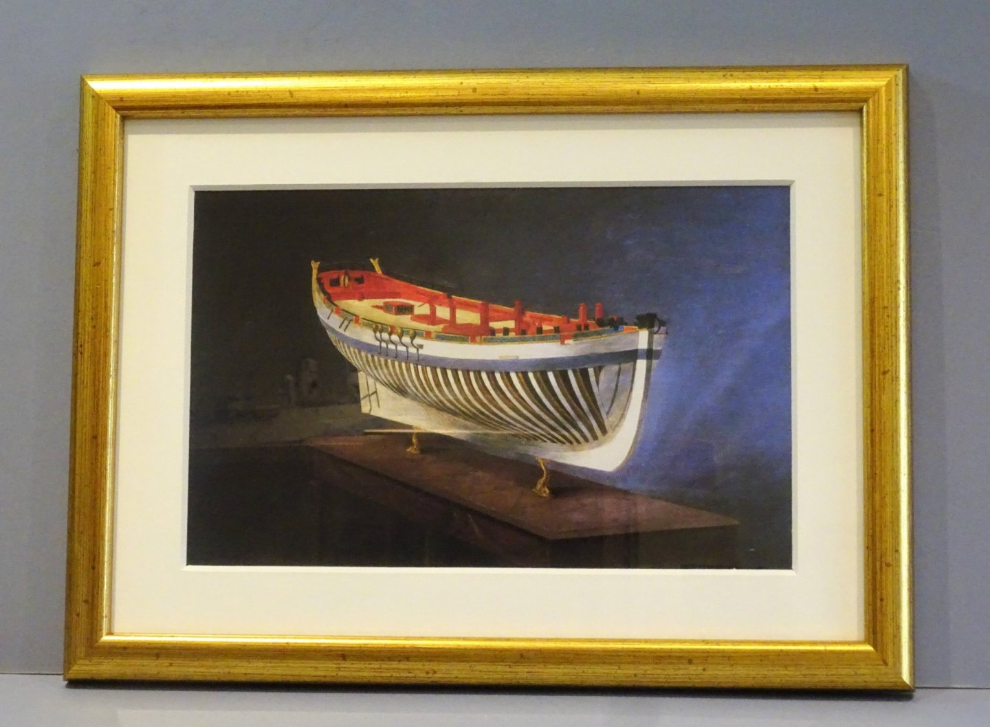
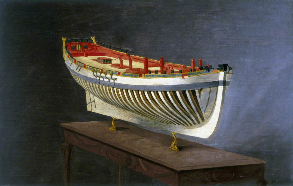
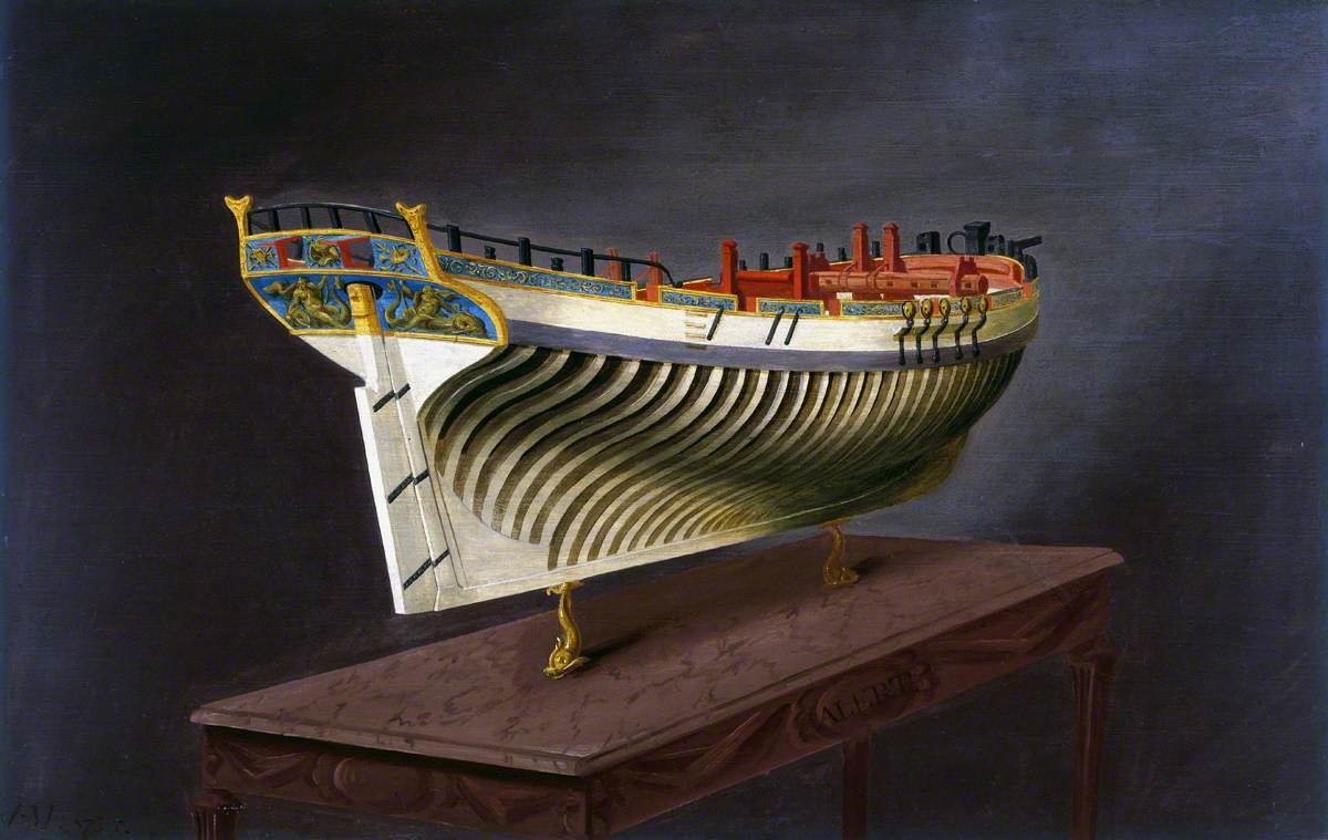
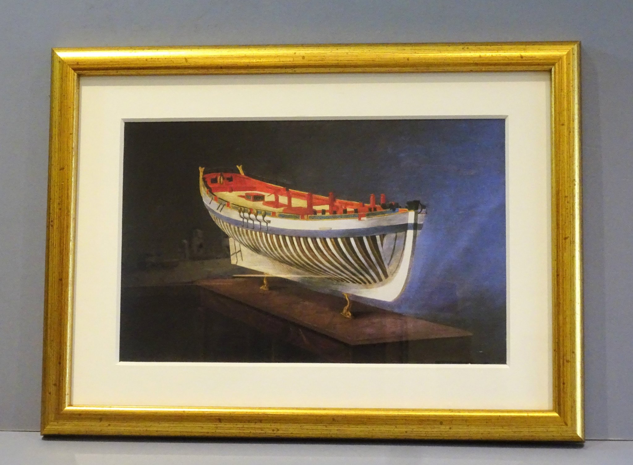
Post 32 A nice delivery arrived today. Whilst I was researching all things Alert, I was much taken by the painting by Joseph Marshall. 3402 When I found out that the Science Museum sold copies, I just had to have one. 3409(2) Can always find room for one more Naval print. B.E. 07/11/2019
.thumb.JPG.4182131289808a8a971a0bb862624f62.JPG)
- 335 replies
-
- 22
-
-
- alert
- vanguard models
- (and 1 more)
-
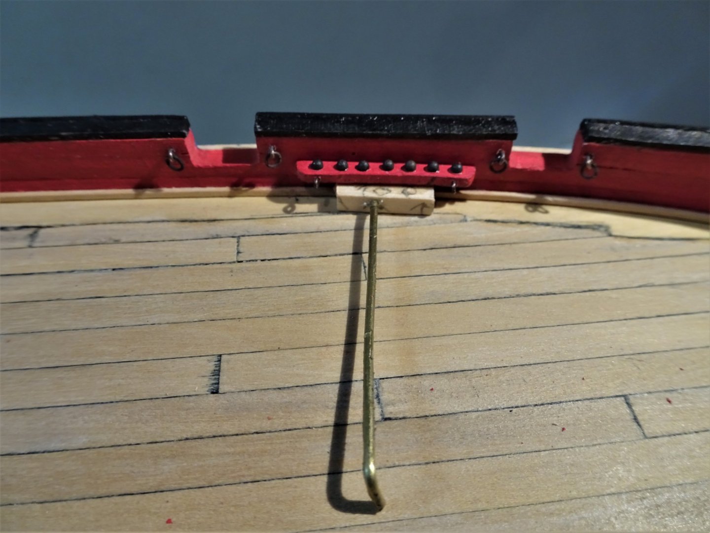
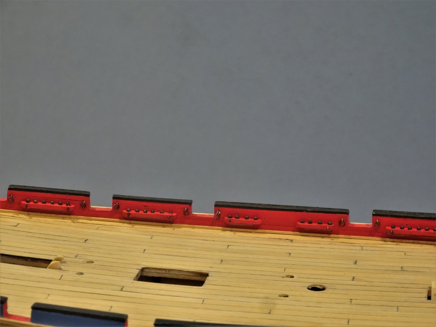
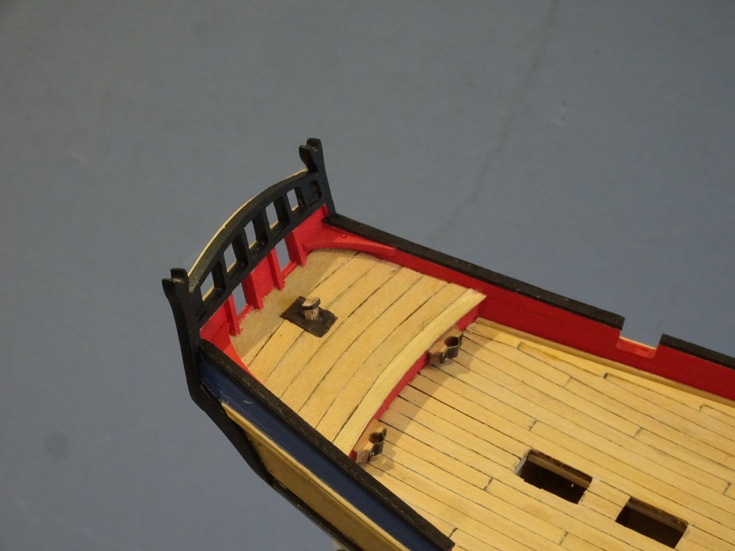
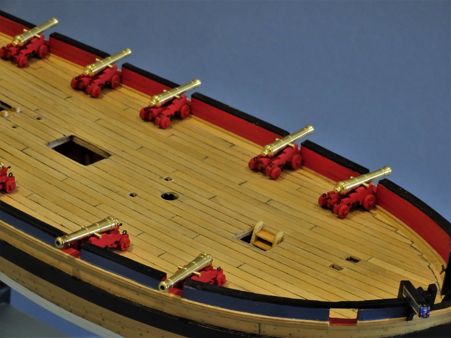
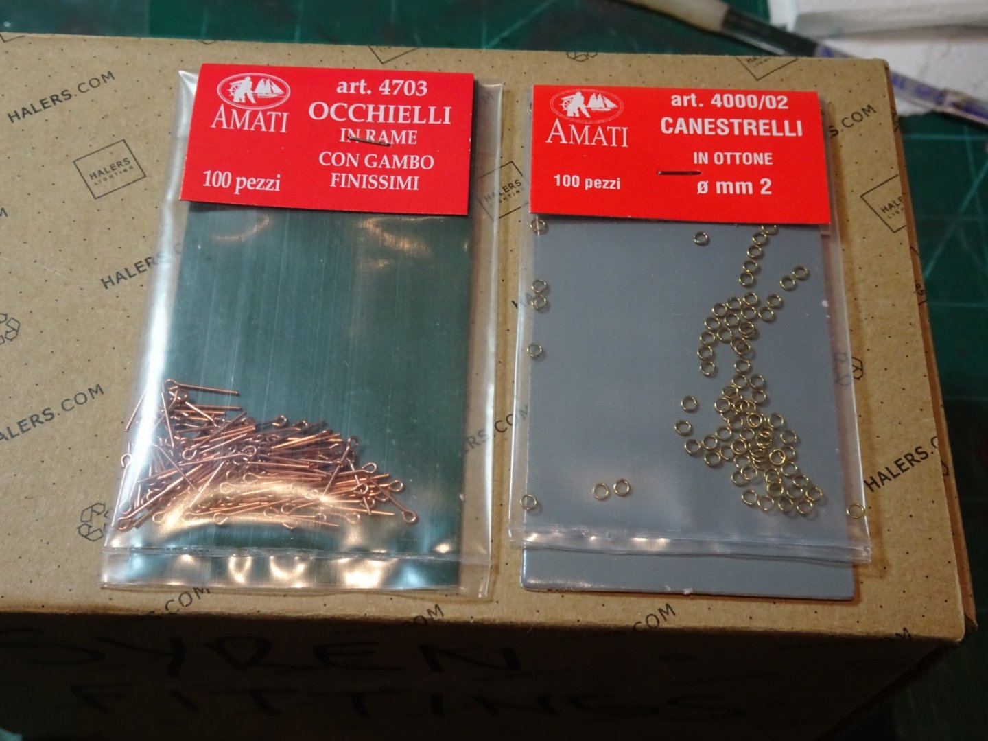
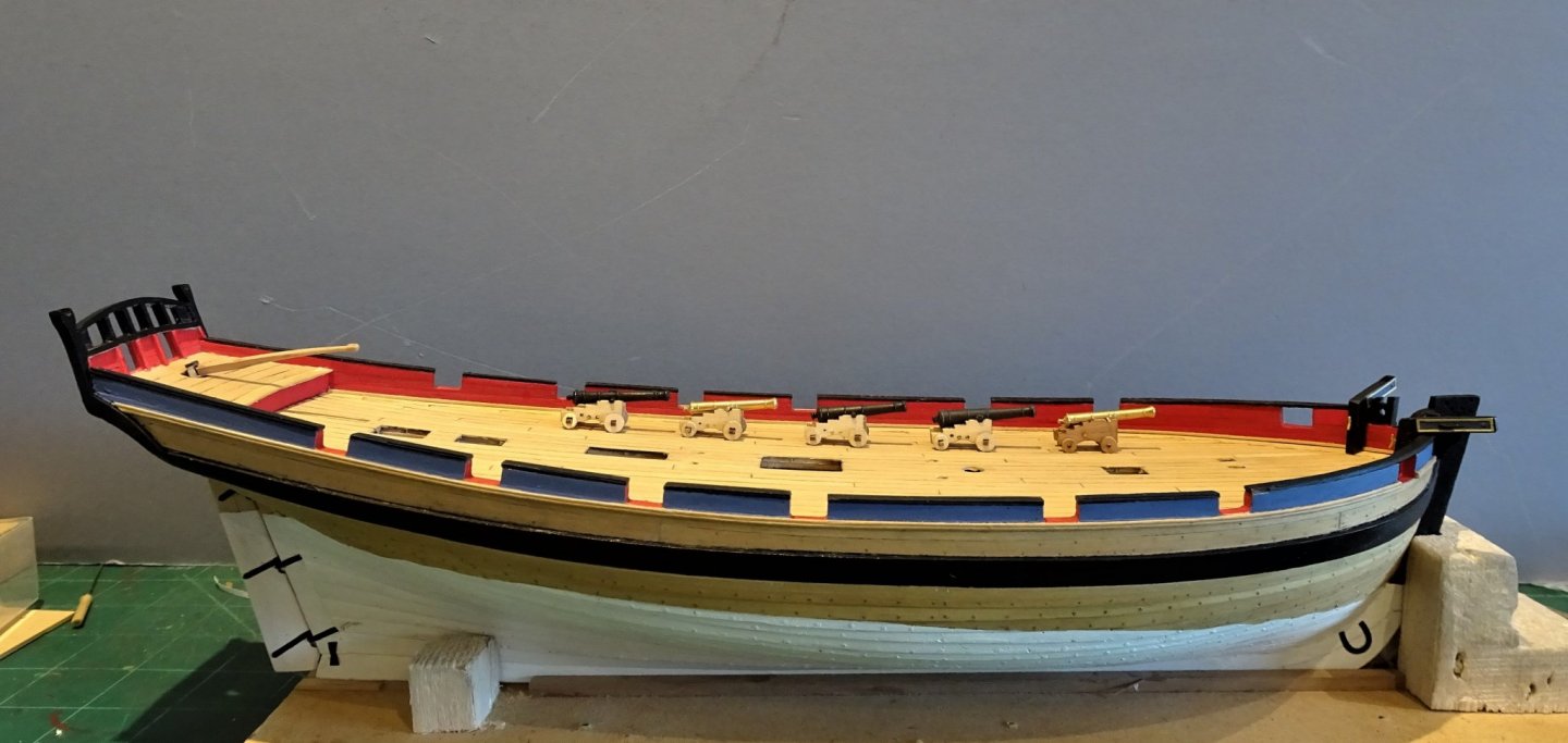
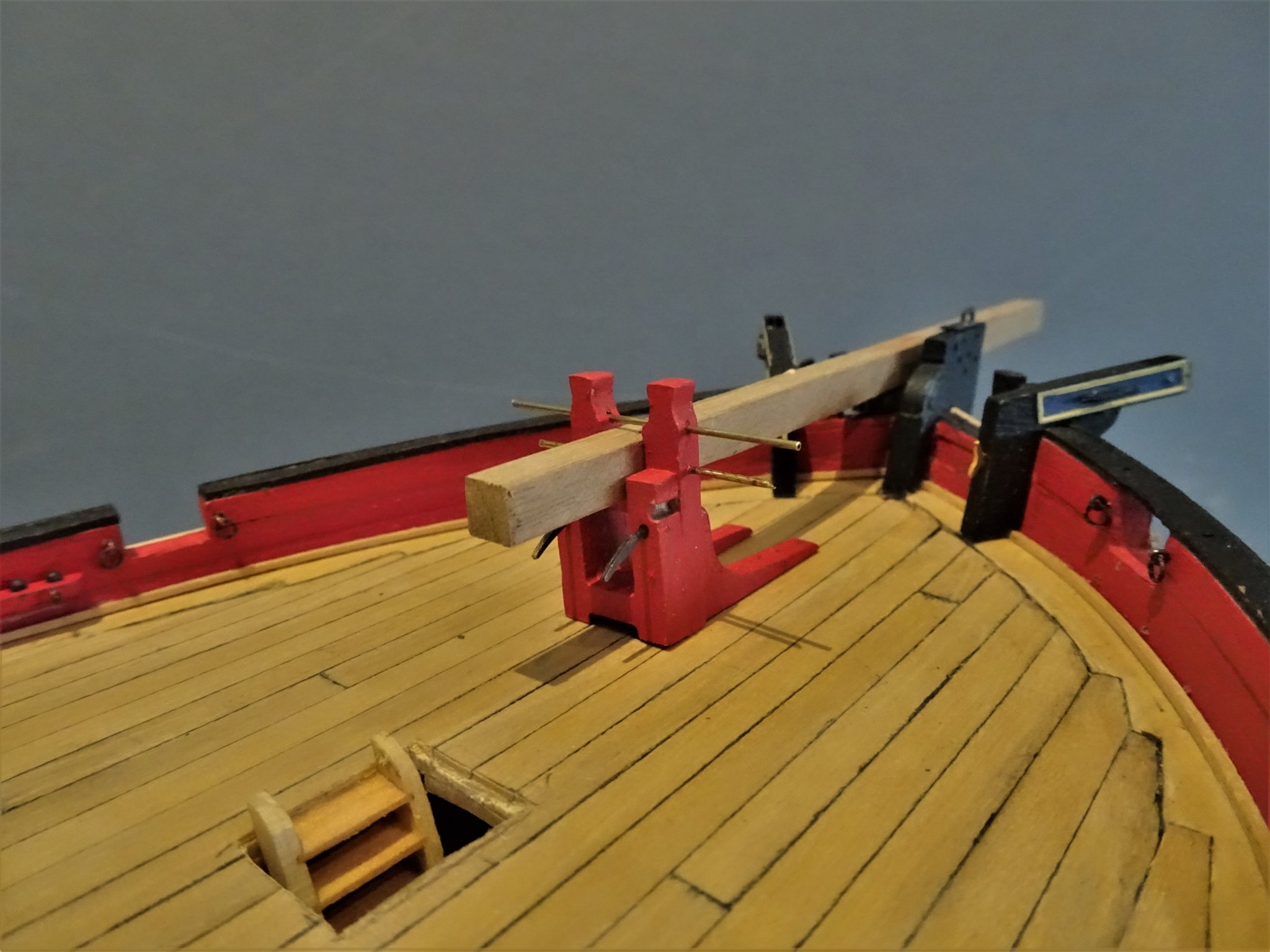
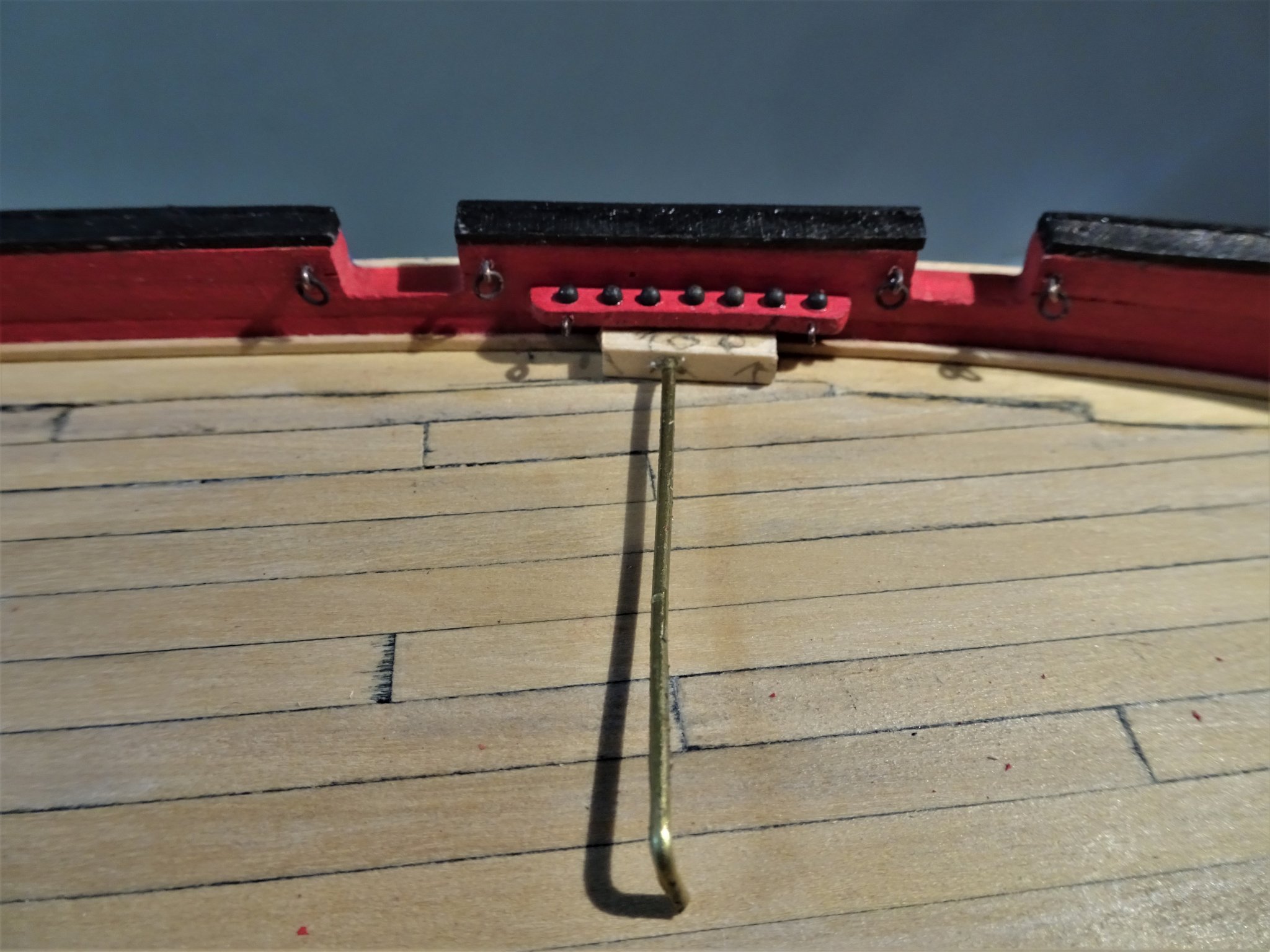
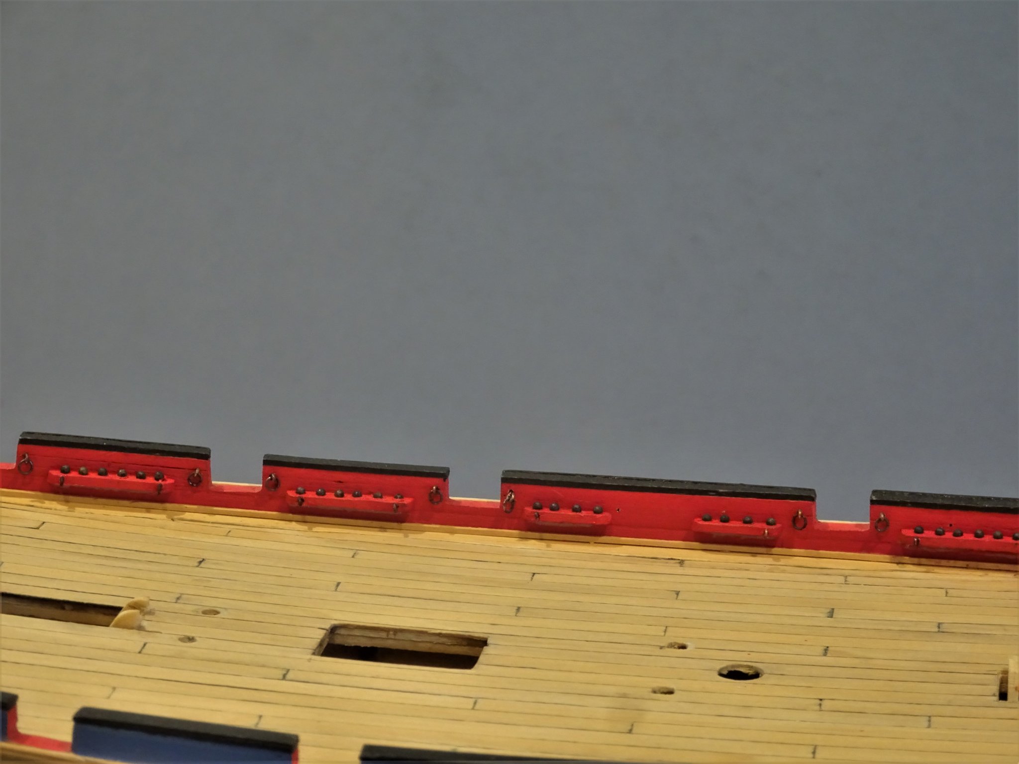
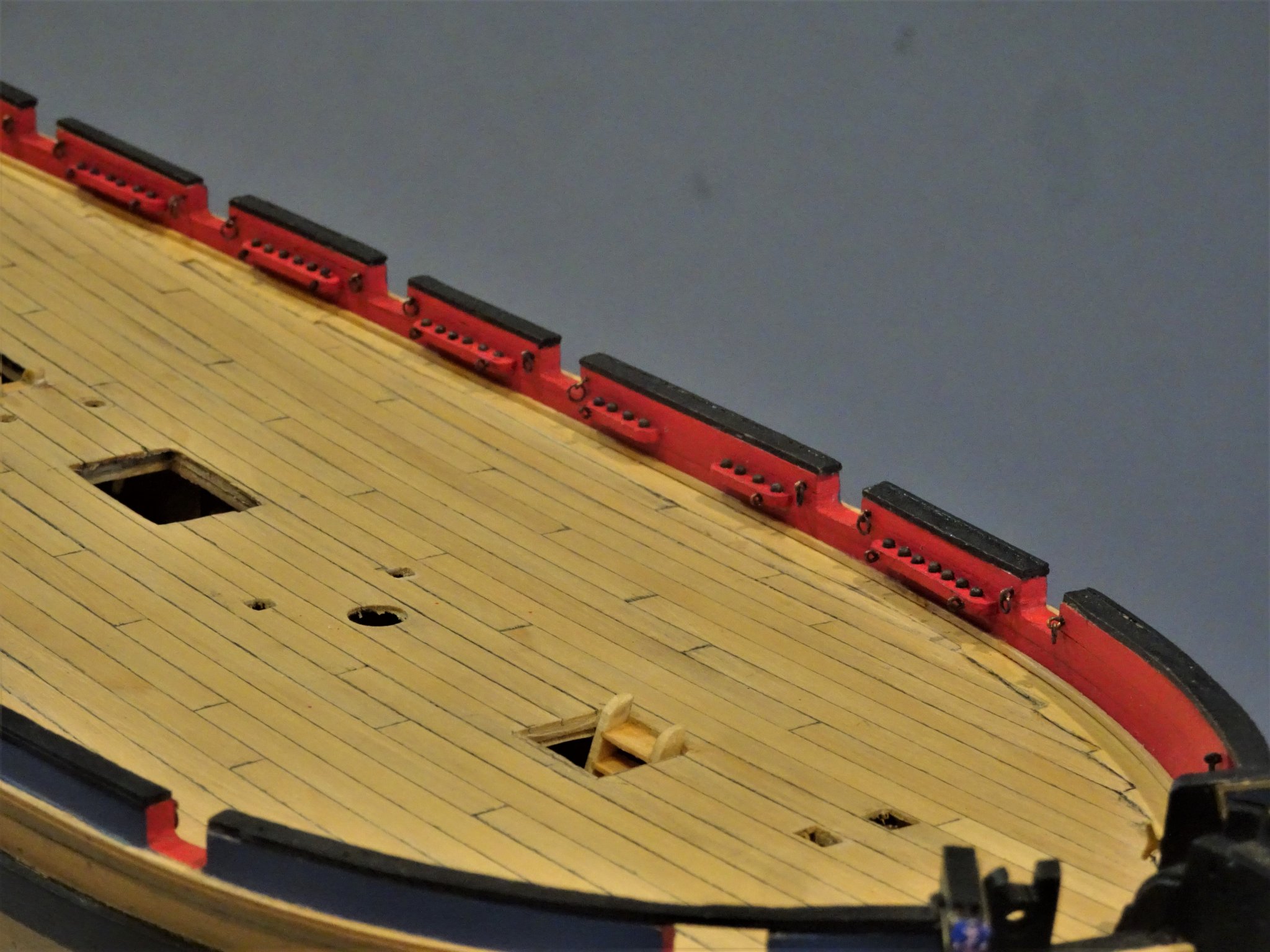
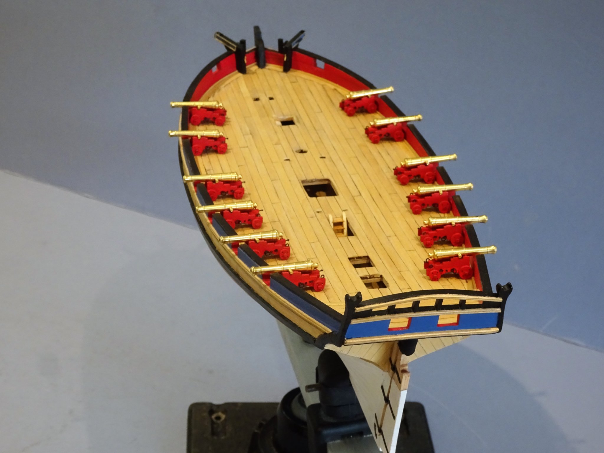
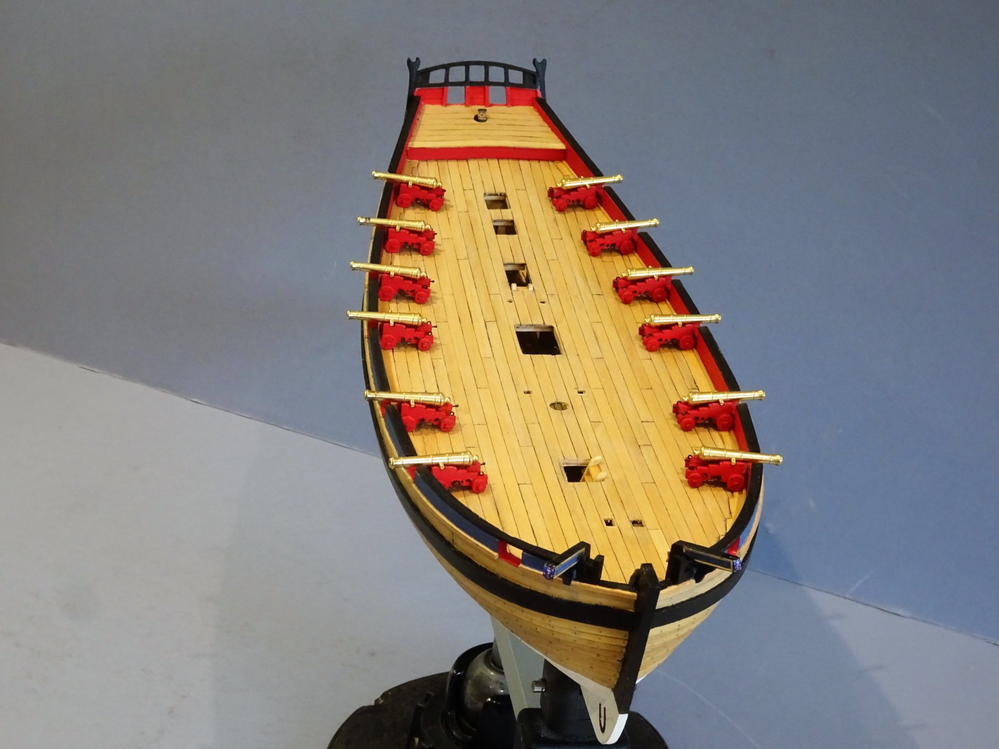
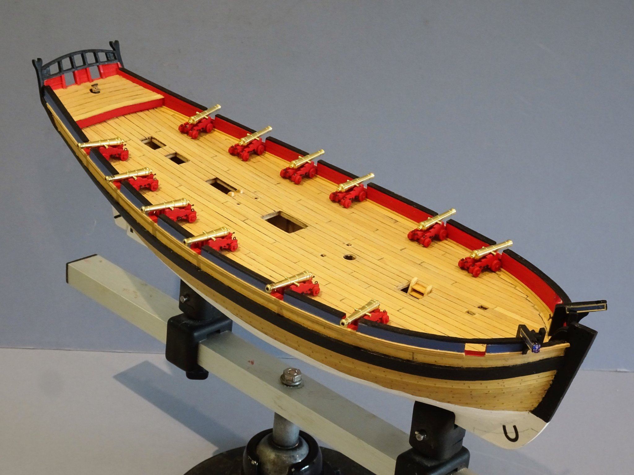
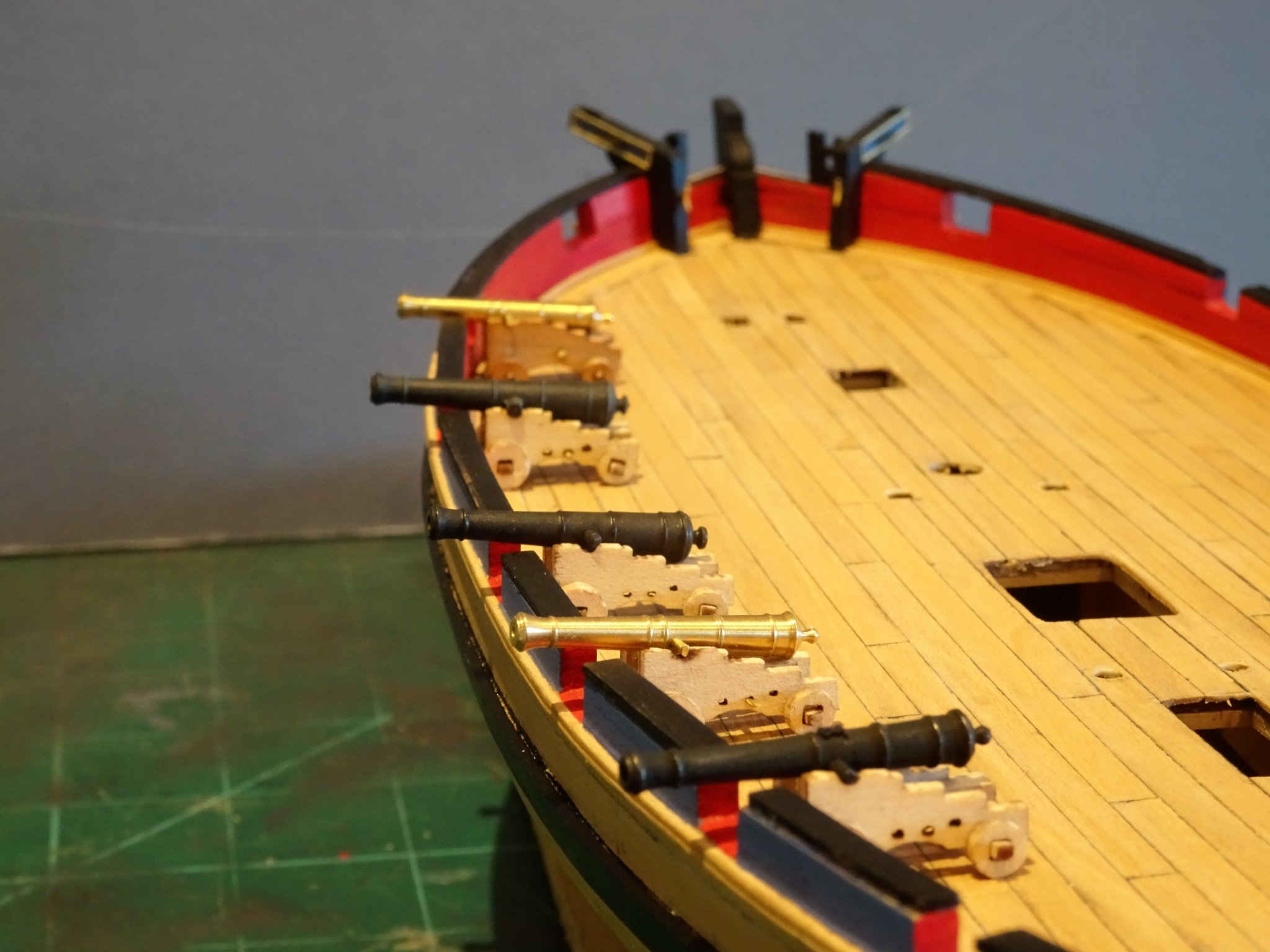
Thanks for looking in Guy, and for your kind appreciation. Post 31 Bulwark attachments This is a good point in the build to deal with the iron work along the bulwarks and other stuff where the centre line fittings would get in the way. Ringbolts and eyebolts for the gun tackle. The kit provides brass pe etch items for the breeching rope ring bolts. All that is necessary is to fit the ring over the open bolt and close it up. However, the kit makes no reference to rigging the guns and if you use the kit tackle and intend rigging, it is wise to check that the intended Breeching rope fits thro’ the provided etch rings. 3381(2) My preferred option is to use Amati fine rings and eyebolts as per the centre example. I think it is appropriate and certainly more authentic at 1:64 scale to rig the guns with breeching ropes and side tackles, and I intend to do so. The main concern is to get the combination and blocks looking right with the carriage. The Breeching rope is 4¼” circ; equating to 0.54mm ø at scale I will use Syren 0.6mm ø line which provides the right visual contrast to the finer tackle lines. I tend to use slightly undersized tackle lines blocks and hooks. There should also be eyebolts to take the side tackle hooks; in the Alert book drawings these are secured to the face of the shot garlands fitted to the bulwark. Shot Garlands These are neat laser cut items and the shot (2mm ø) is also provided. My immediate thought was that the provided shot looked at tad overscale. Naturally I couldn’t resist trying the ball for fit in the muzzle and not surprisingly it doesn’t. The bore for a six pounder is given as 3.675” (how did they measure that close with the technology they had at the time) with a 3½” ø ball. At scale the bore works out at 1.46 mm. and the model gun is 1.56mm; 1.50mm ø shot it is then. 3380(2) This did mean I had to modify the Garlands to take the smaller shot. On the left, 2mm shot; on the right, 1.5mm shot. 3384 Tricky little items to fit I used a guide to get the right height. 3399 The ring bolts for the Breeching ropes are not fixed at this time, they will be attached to the ropes before gluing to the bulwarks. While I was looking at the shot garlands and their position along the bulwarks, I became aware of differences between the kit and the Alert book drawings. There is a much greater spacing between the third and fourth ports from aft on the book drawings, (C2/1) which appears between the fourth and fifth from aft in the kit. The kit follows the arrangement on the Admiralty drawings. The book deck plan drawing(C2/1) shows a longer garland accommodating 11 balls. On the Admiralty plan there are two smaller garlands which seems more logical as a continuous rack would be over eight feet in length. The kit provided garland sits centrally within the greater space which is relevant because as noted earlier the side tackle eyebolts are fixed to the garlands. 3395 I added two shorter Garlands within the space which maintains the continuity of the side tackle arrangements. 3392(2) Not sorry to see the end of this fiddley little exercise. Movin’ on. B.E. 06/11/2019
.thumb.JPG.f5d905fbaa02fbfd88efc5c97880eabb.JPG)
.thumb.JPG.88fd82a7bcc883048e2a37419bb10a92.JPG)
.thumb.JPG.1f950b7896bd1a19d2af0ab024145376.JPG)

- 335 replies
-
- 19
-
-
- alert
- vanguard models
- (and 1 more)
-
It’s a pleasure to follow your builds Nils, you choose such interesting subjects and apply such innovative skills, great job.👍 B.E.
-
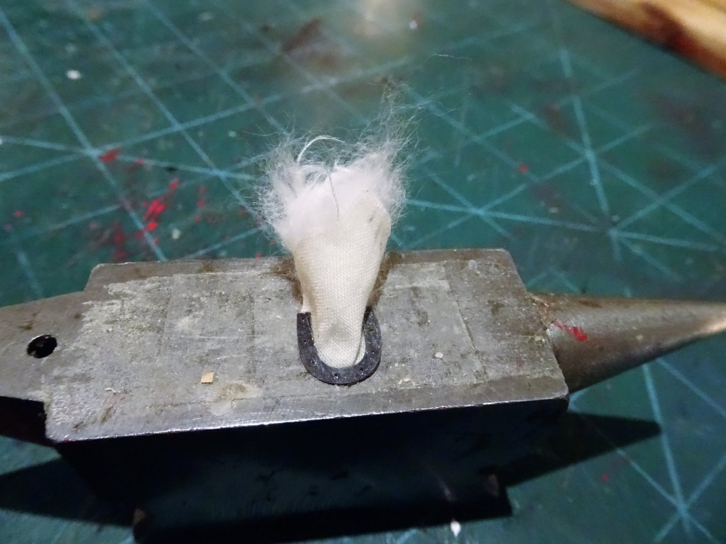
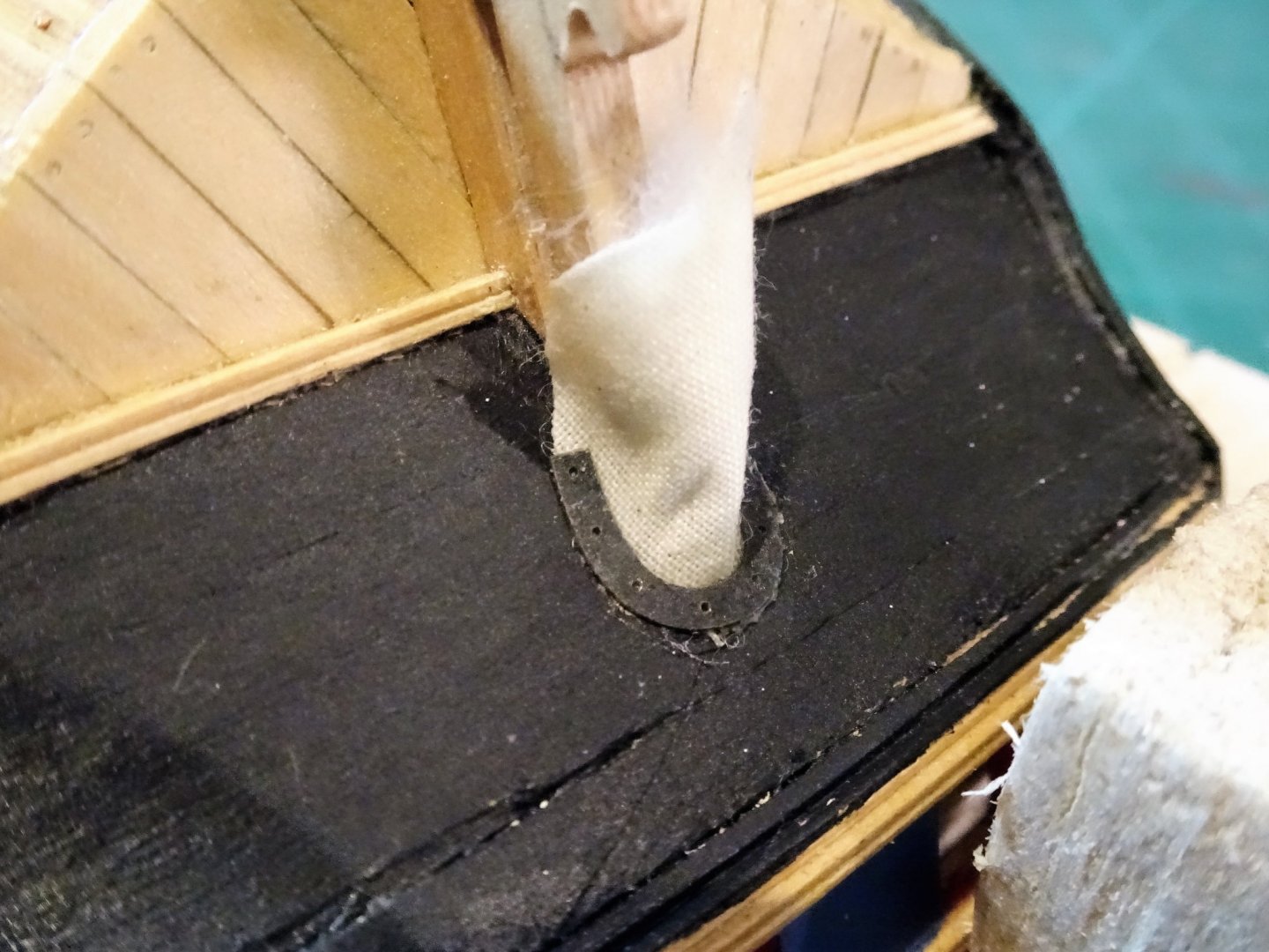
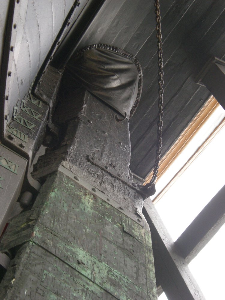
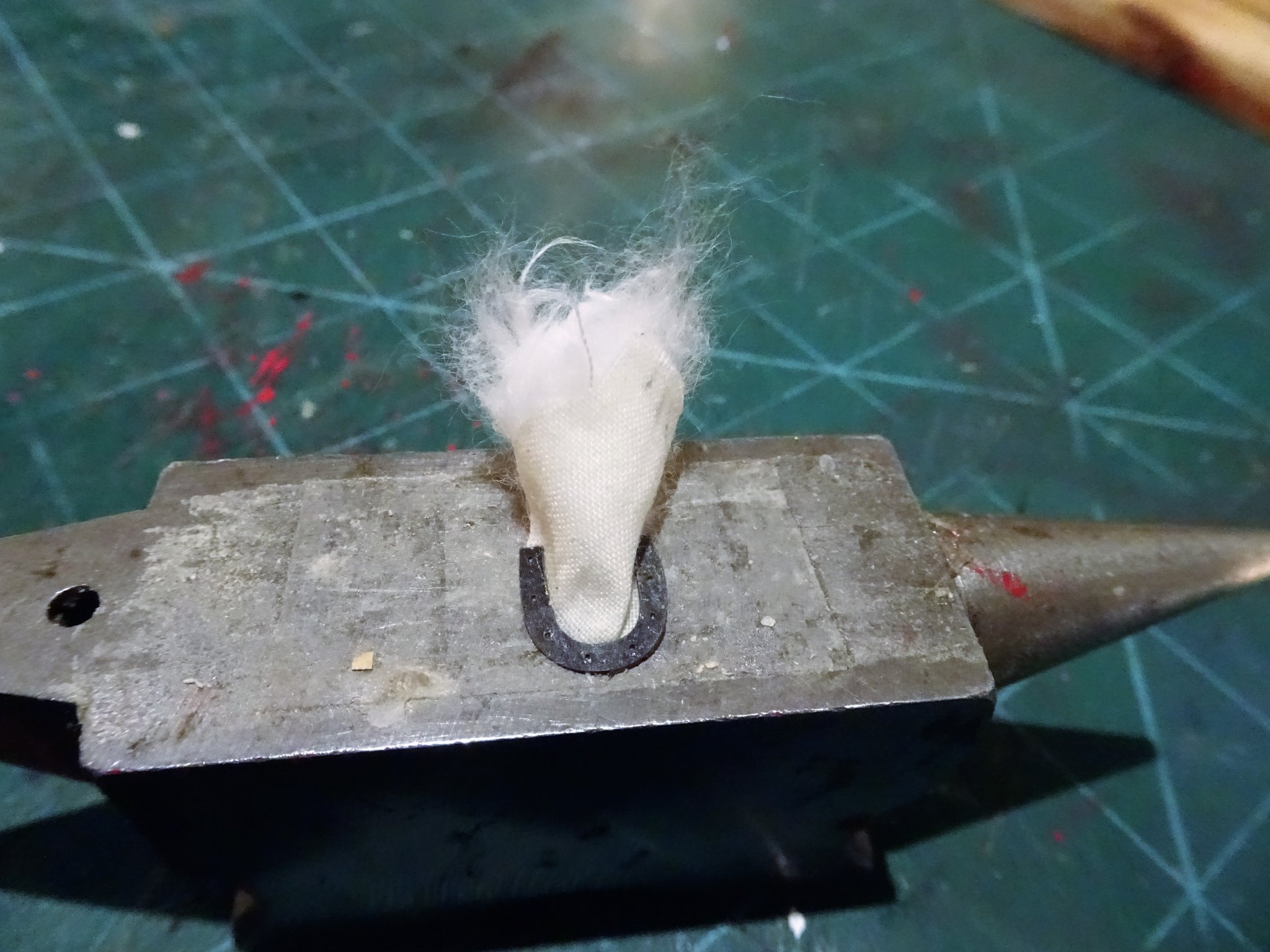
Thanks, Nils and Dirk, once they've been adorned with Chuck's little Royal monograms, and blackened I think they'll look spot on. 🙂 Post 30 - Bits and pieces. The Rudder coat If I am to fit one of these it is best done whilst I can still invert the hull free of all the deck fittings. I fitted one to Pegasus and I thought one would be appropriate for Alert. I am thinking of water constantly entering the space below the platform deck that would be inevitable without one. These are tricky little additions to visualise and there is an element of trial and error involved in their making. This is a shot of the Rudder coat on Victory. Not of a particularly aesthetic appearance they attach around the rudder head below the counter, and spread out to cover the rudder port, whilst retaining an element of bagginess to allow the rudder movement. I make mine from fine handkerchief cotton, the initial pattern is sort of light bulb shaped and having drawn out the pattern the edges are sealed with pva to avoid fraying when cutting out. The difficult part is building in an element of ‘bag’, as the natural inclination is for the coat to cling too tightly to the counter. I try to get around this by using cotton wool to fill out the coat before I seal it down. I remember thinking when I was building Cheerful that those little fibre Horseshoe plates supplied by Chuck may come in useful when fitting a rudder coat to secure the edges to the counter. Now is the time to find out. 3321 Stage one is to glue the horseshoe to the outer edges of the coat, whilst pulling up the centre to provide some bag. Stage two is to use strands of cotton wool to partly fill out the bag. 3323 Stage three is to glue the assembly thus far to the counter. Once set one side of the bag is glued to the rudder head. 3326(2) The bag is then carefully manipulated adding further strands of cotton wool, before gluing the other side to the rudder head. Any excess of cotton is painted with diluted pva, and when dried a scalpel blade is used to trim the edges on the rudder head. 3337 3333 3329 The coat can then be painted with diluted black paint to represent the tarred surface. Where there’s a rudder coat there is a helm coat, I made mine using microporous tape, useful stuff where small areas of tarred canvas are required. 3357 The photo also shows the Transom Knees, and Mizen Mast Steps. The kit provides these together with brass etched brackets. The items are well shaped and represent a combined step to the counter deck and support for the Mizen Mast. 3354(2) I slightly modified the bracket to suit a 3mm ø Mizen mast. According to the detail in the Alert Book, the mast is given as 37’ 2” height with an 8”ø This equates to a scale 177mm length with a 3.1mm ø I will make the mast and store it on the deck. Scuppers. To scupper or not to scupper No scuppers are shown on any of the drawings in the Alert book, and there is only a passing mention of them in the narrative relating to the deck pumps. Likewise, they are not included as a feature in the kit. The only model I have seen showing Alert with scuppers is a beautiful 1:48 scale scratch-built version completed by Daveyjones back in 2014; that really is a very fine model, check it out in the Gallery. I think I will defer the decision for while even tho’ logic tells me that even a low freeboard boat such As Alert would have them. B.E. 03/11/2019
.thumb.JPG.e52da4ccc963fa400f43af253c95ac4b.JPG)


.thumb.JPG.14c79bfa01b6fa78932f71020d4b1b09.JPG)
- 335 replies
-
- 18
-
-
- alert
- vanguard models
- (and 1 more)
-
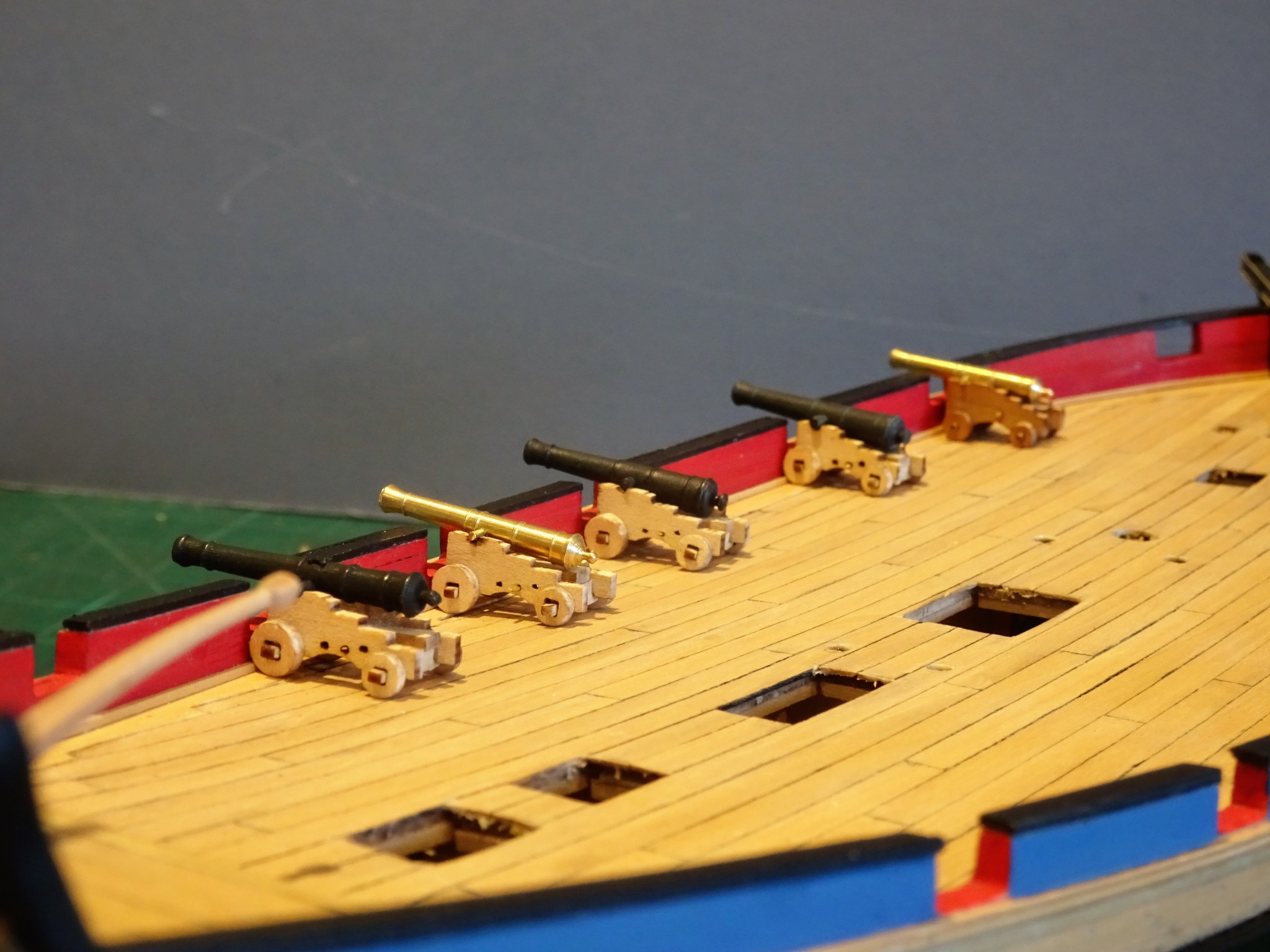
Thank you Dirk, Rusty, and Jim. 🙂 Post 29 Today I received the replacement ordnance for Alert. 3352 3349 3350 3351 These are 29mm Brass guns from RB Models, Poland, and represent good value at £10.00 delivered. The carriages are the kit provided ones. I can now move onto completing the guns. B.E. 31/10/2019


- 335 replies
-
- 19
-
-
- alert
- vanguard models
- (and 1 more)
-
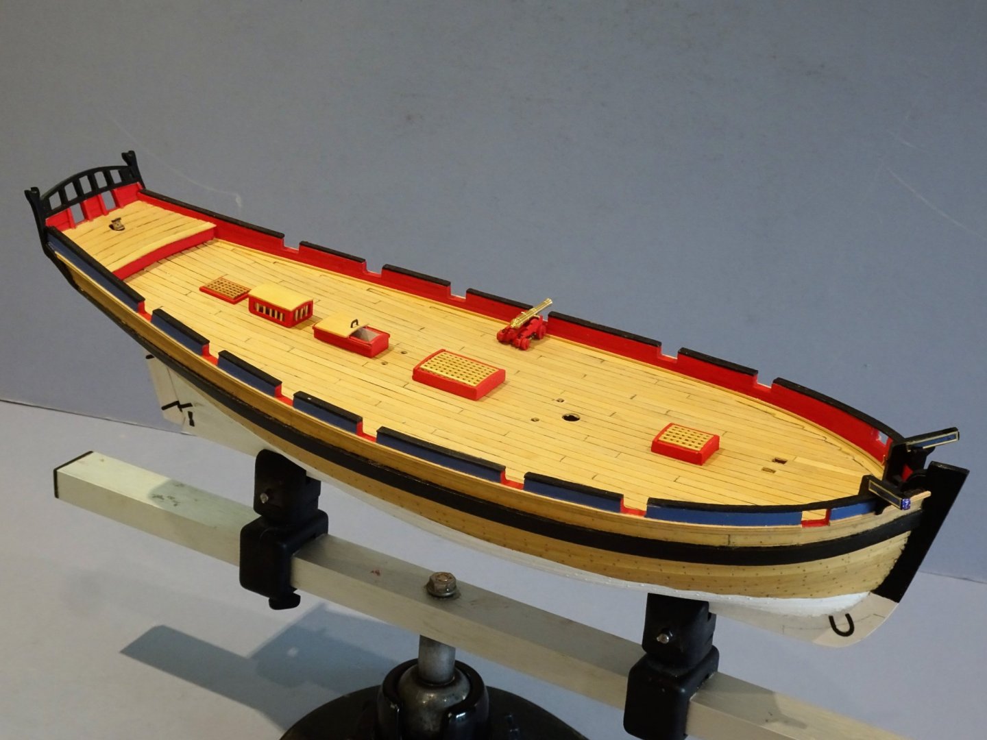
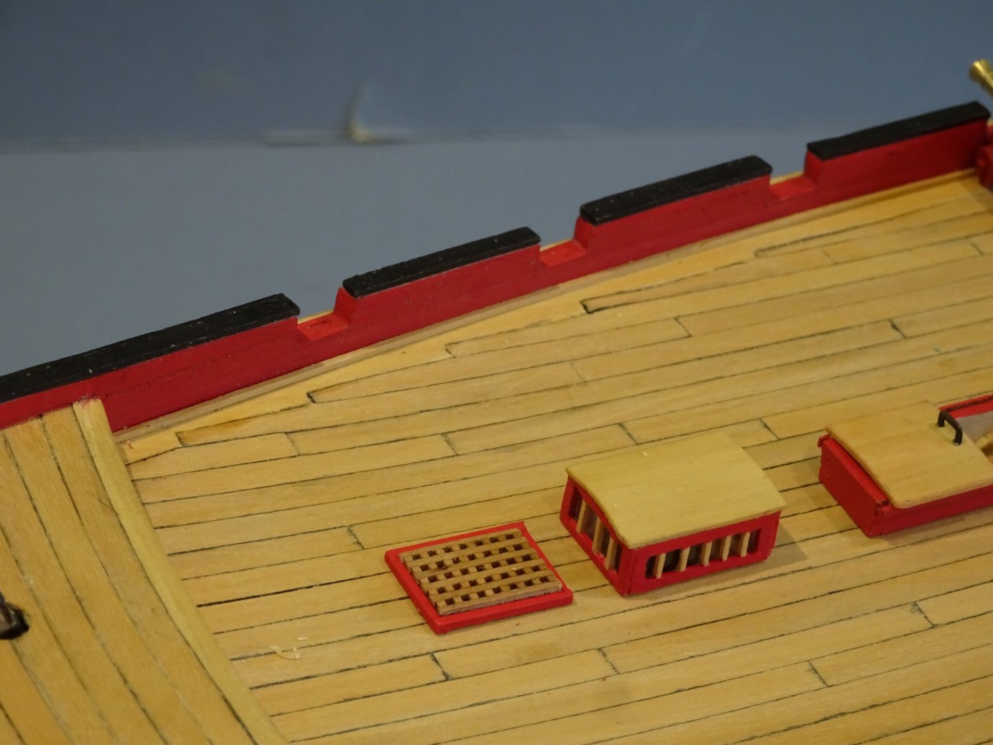
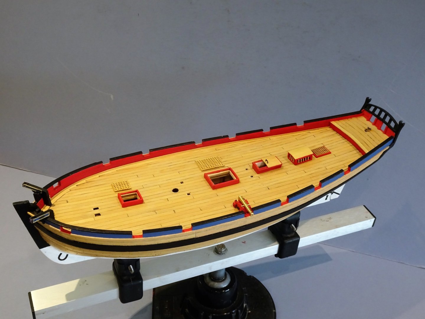
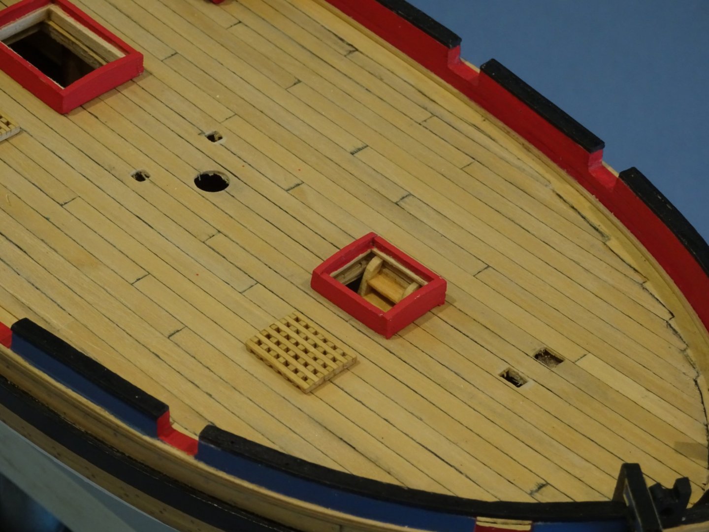
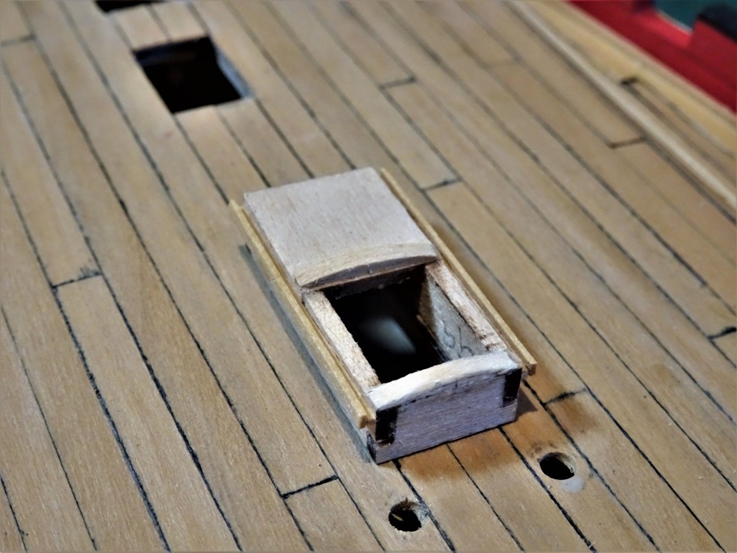
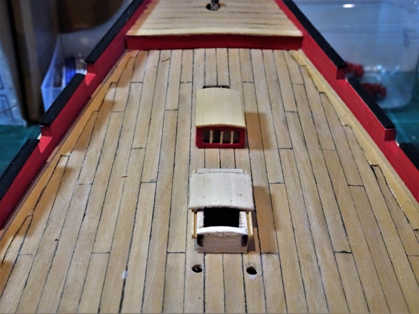
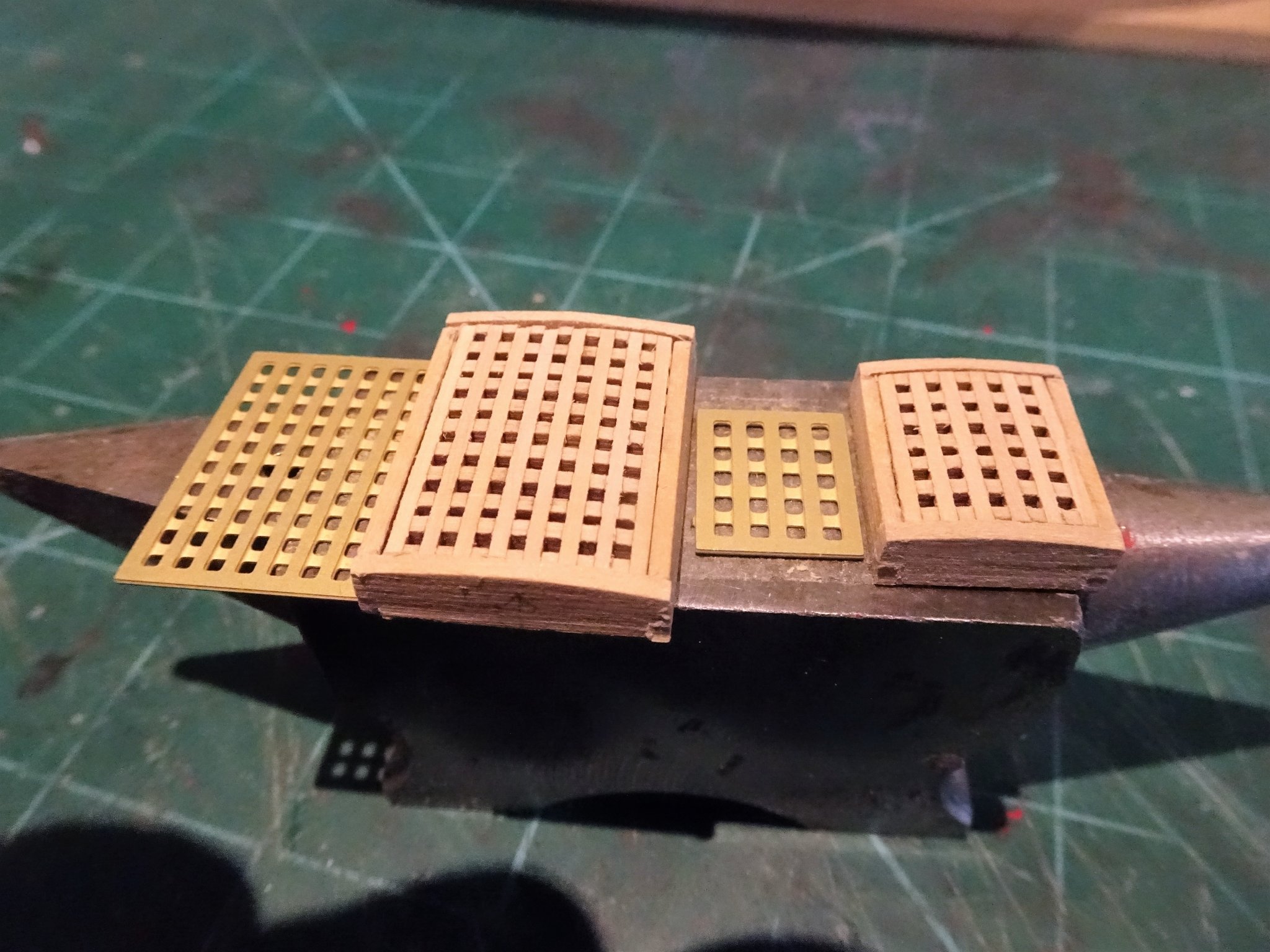
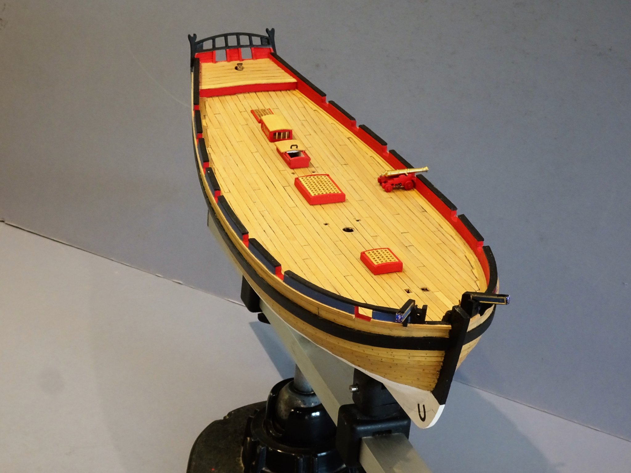
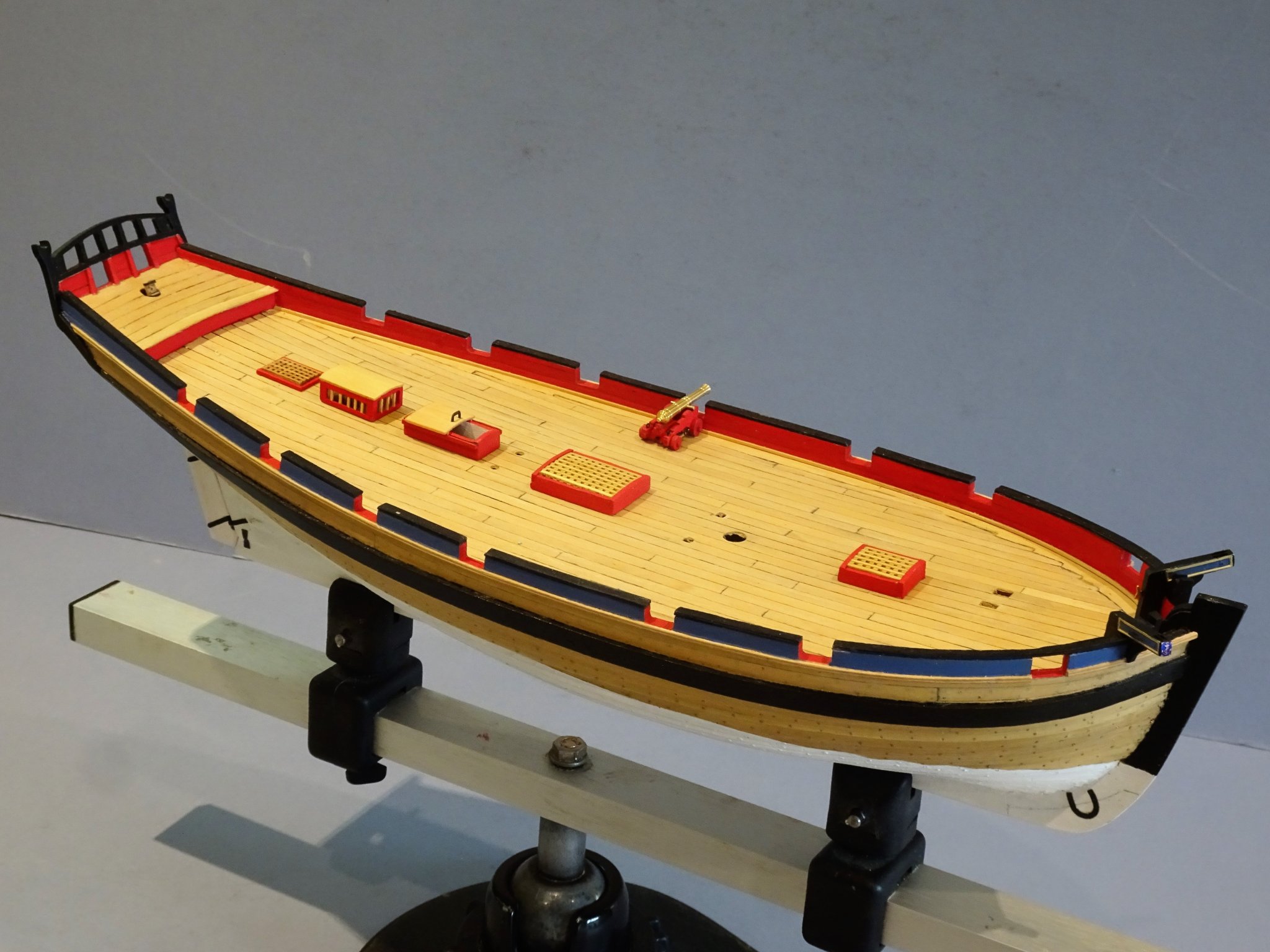
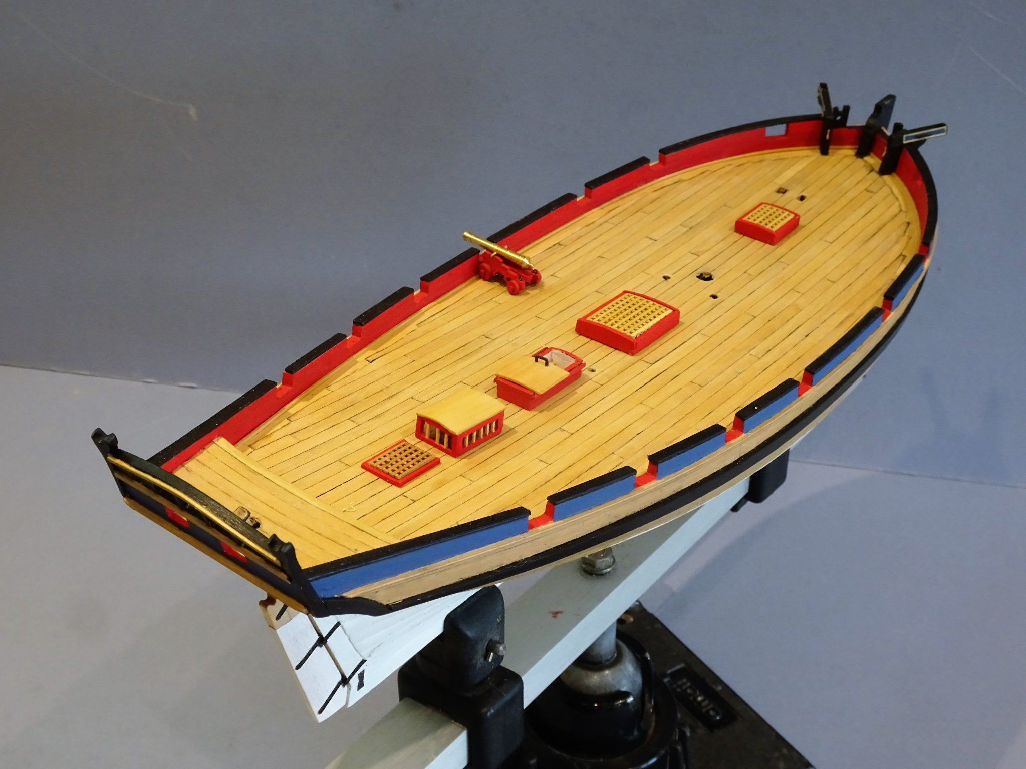
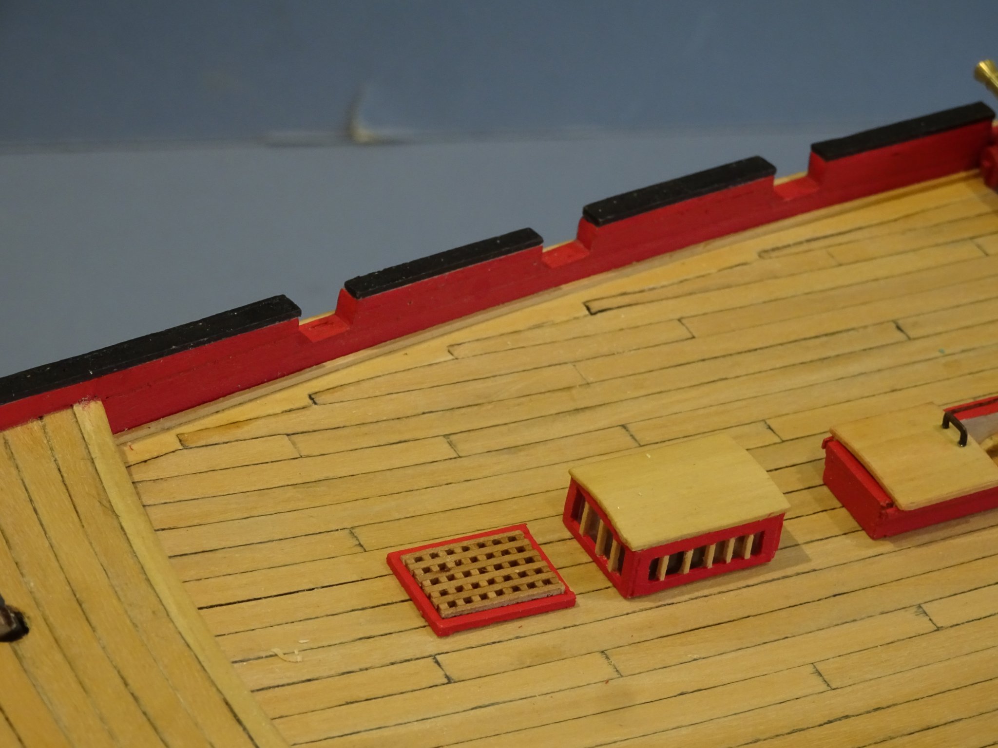
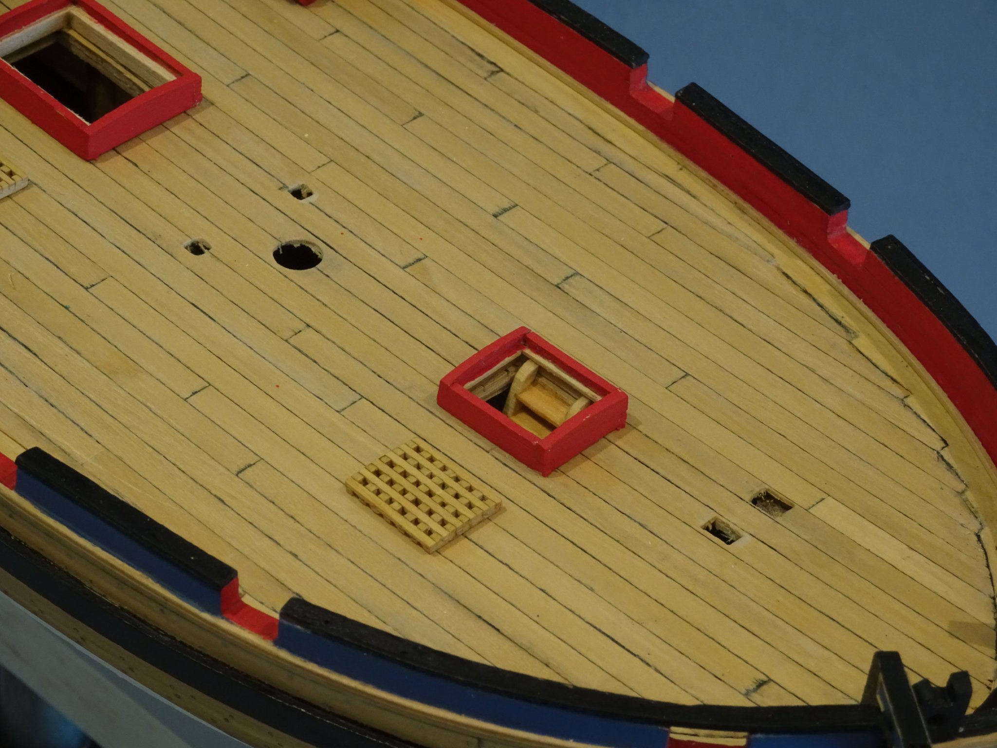
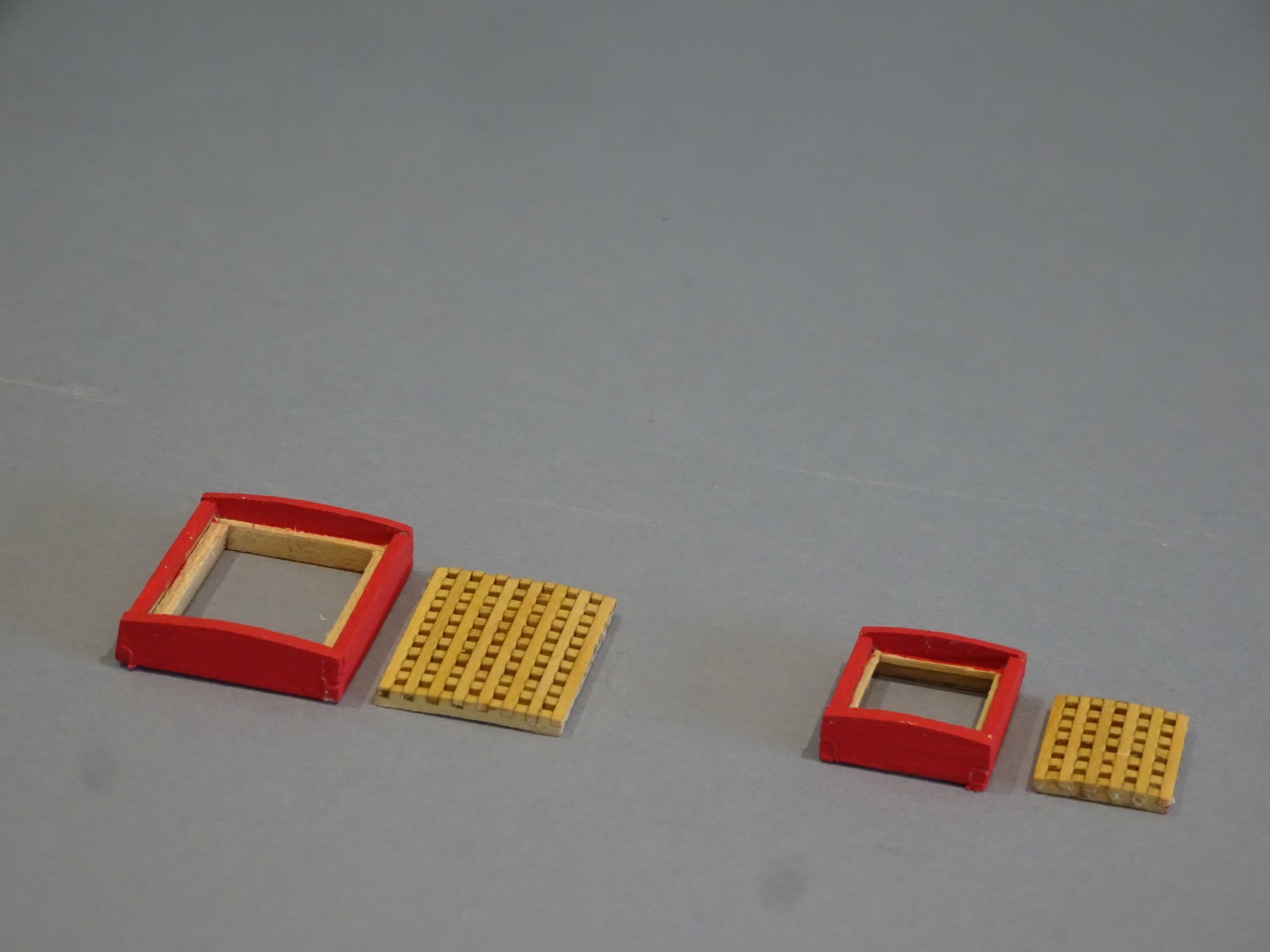
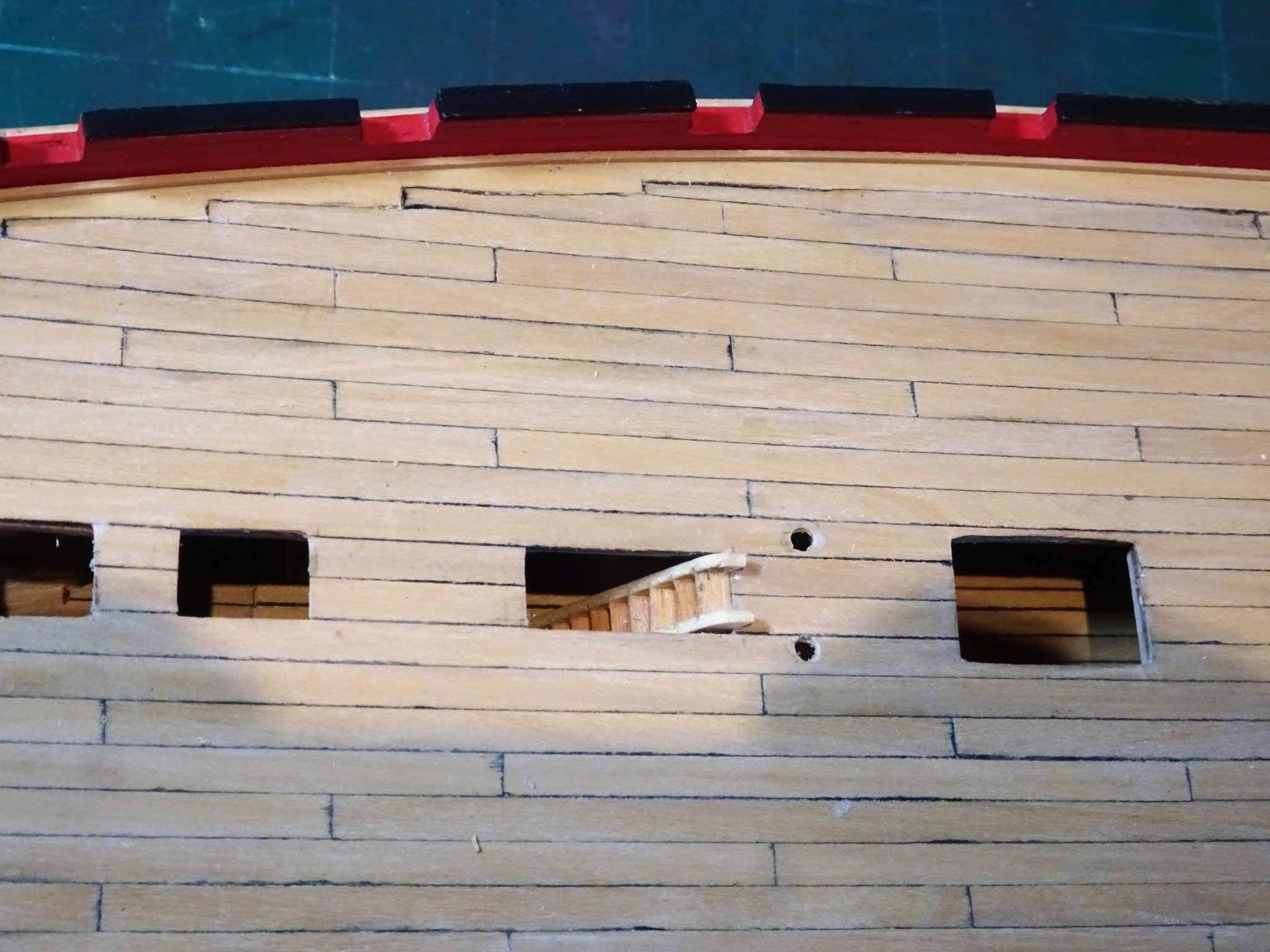
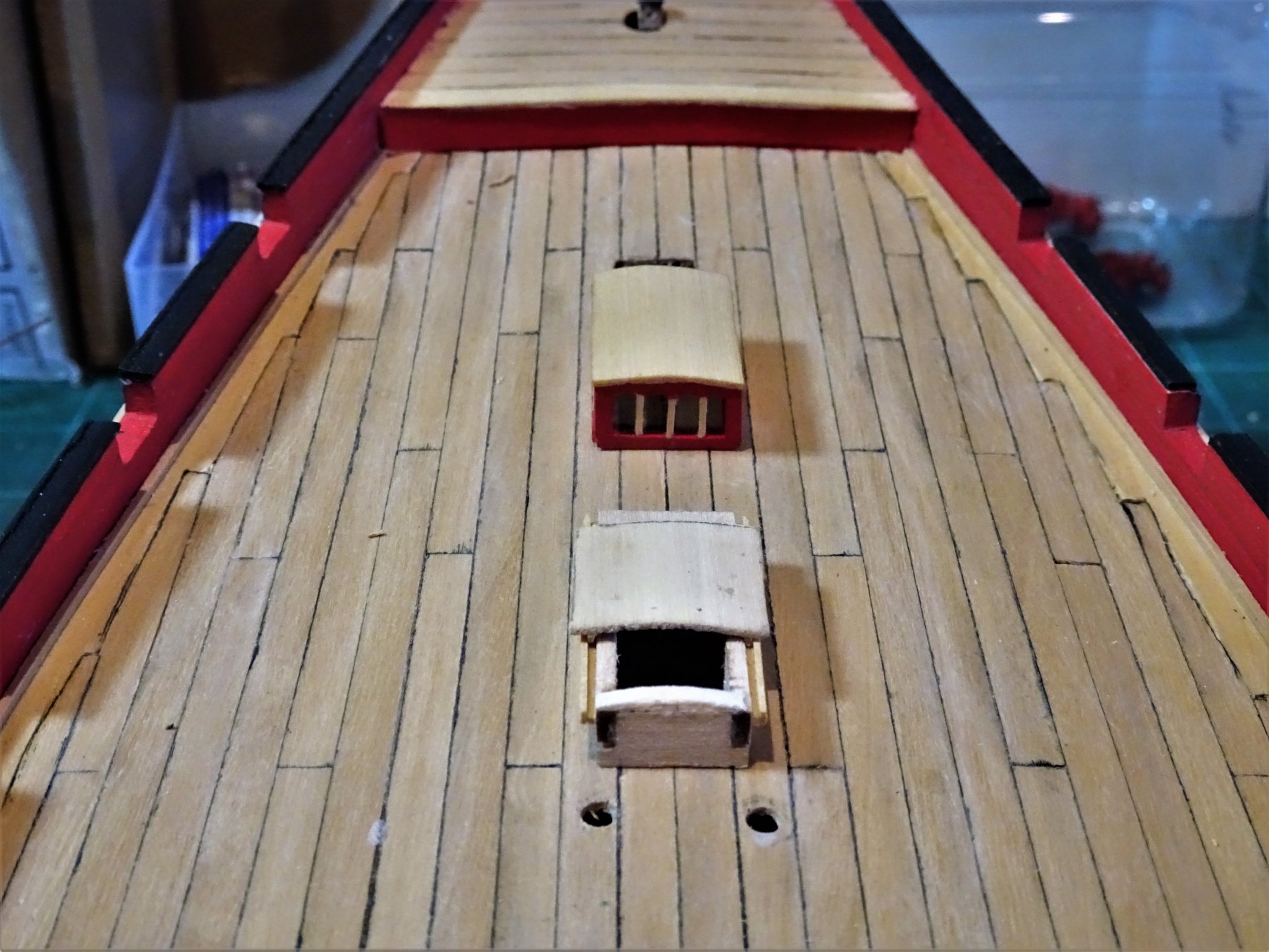
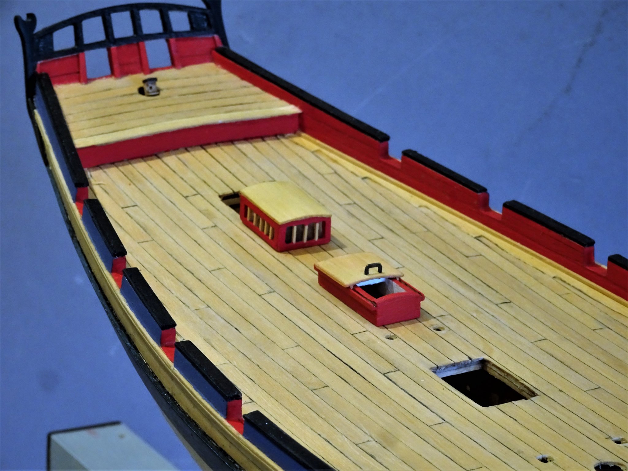
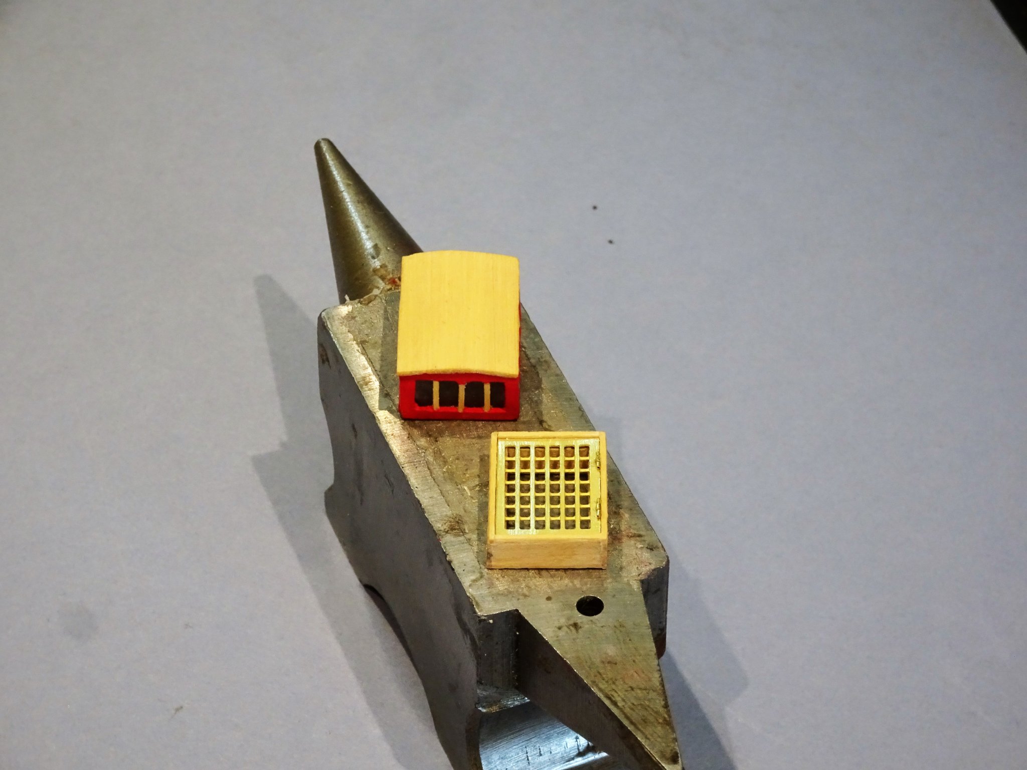
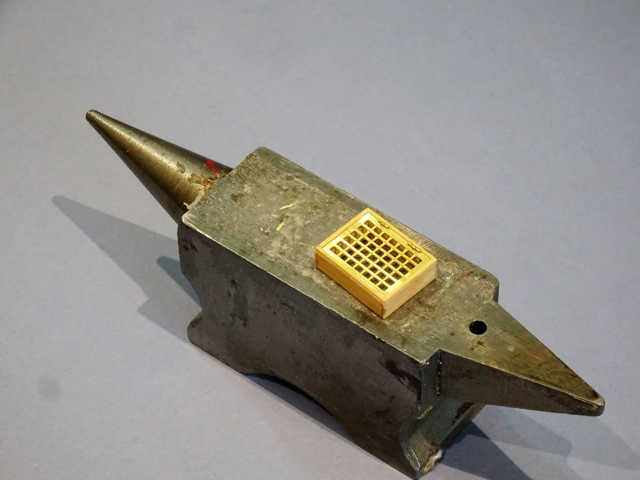
Post 28 Hatches Main Hatch The kit provides a quick and easy method of assembly with pre- cut joints for the Head ledges and coamings, and pe brass gratings. A simple arrangement, and this is the first kit I have come across with brass etched gratings. A good idea perhaps at smaller scales but for me wooden gratings look better and are perfectly feasible at 1:64. The Head ledges lack any round up, and the brass gratings also lack the cut-outs to allow passage of the anchor cables, but I suppose the brass ones could be carefully modified. 3294 My approach is to use the brass grating as a template to form a Boxwood version, and then build the head ledges and coamings around that, also in Boxwood. Altho’ the framing will be painted the Boxwood will provide a far better surface to take the paint. 3316 For the Gratings I am using Chuck’s (Syren) Cambered Boxwood strips and grating jig. These are a good match for scale and take all the pain out of grating construction. Fore Hatch 3315 I also adopted the same approach to the Fore hatch and replaced the kit gratings with wooden versions, and included the ladder leading down to the lower deck. The Bread Room scuttle This is represented in the kit by a solid cover whereas the Alert book drawings show it as a grating. On my kit the laser cut lid was a poor fit to the provided frame and I discarded both. 3308 Because I like gratings better than covers, I went with a grating. This grating is not one of Chuck’s, but a temporary fitting until fresh supplies arrive. 3298 3299 3302 3304(2) 3313 Having made a few fittings, I will now return to do a few other necessary jobs on the hull, scuppers, ring bolts for the bulwarks, and a rudder coat come to mind. B.E 30/10/2019


.thumb.JPG.a1712c7fdcfb8f6eb9b78e41a1dbfada.JPG)

- 335 replies
-
- 18
-
-
- alert
- vanguard models
- (and 1 more)
-
Cheers Dirk, and thanks for looking in Ricky, glad you like it. Post 27 Main Companion way The style has been taken from the Alert book drawings and is the traditional sliding canopy form. It fits well on the 1:64 scale drawing in the book. The head ledges have been represented and the pre-formed parts fit together well. That said there are a few enhancements that can be made to improve the look of the item. The canopy is a tad thick and could stand some thinning down and the fixed part of the canopy has a slight overhang whereas it should really sit in a recess around the head ledges and coaming. 3244 I replaced the sliding canopy with some thinner Boxwood sheet and added a slight round up to the head ledges, which allows for a corresponding curve in the canopy. 3269 I added the runners to the sides so the canopy roof can move to the open position. 3247 I had early in the build installed a lower deck, and a ladder was constructed which can be seen below the open canopy. This is simply to give depth to the model and the impression that it is more complete than it is. 3272 Construction completed, cleaning up and painting now follows. The wood used for the laser cut parts is quite soft and grainy, this is not unusual in kits and is down to cost. 3286(2) I find it difficult to get a good finish even with multiple coats and fine sanding. 3282 3281(2) B.E. 28/10/2019


.thumb.JPG.5912f465a151fd4210a3bf314a780a7b.JPG)
.thumb.JPG.46616cea51378d75d15ba0a2021b2f8c.JPG)
- 335 replies
-
- 20
-
-
- alert
- vanguard models
- (and 1 more)
-
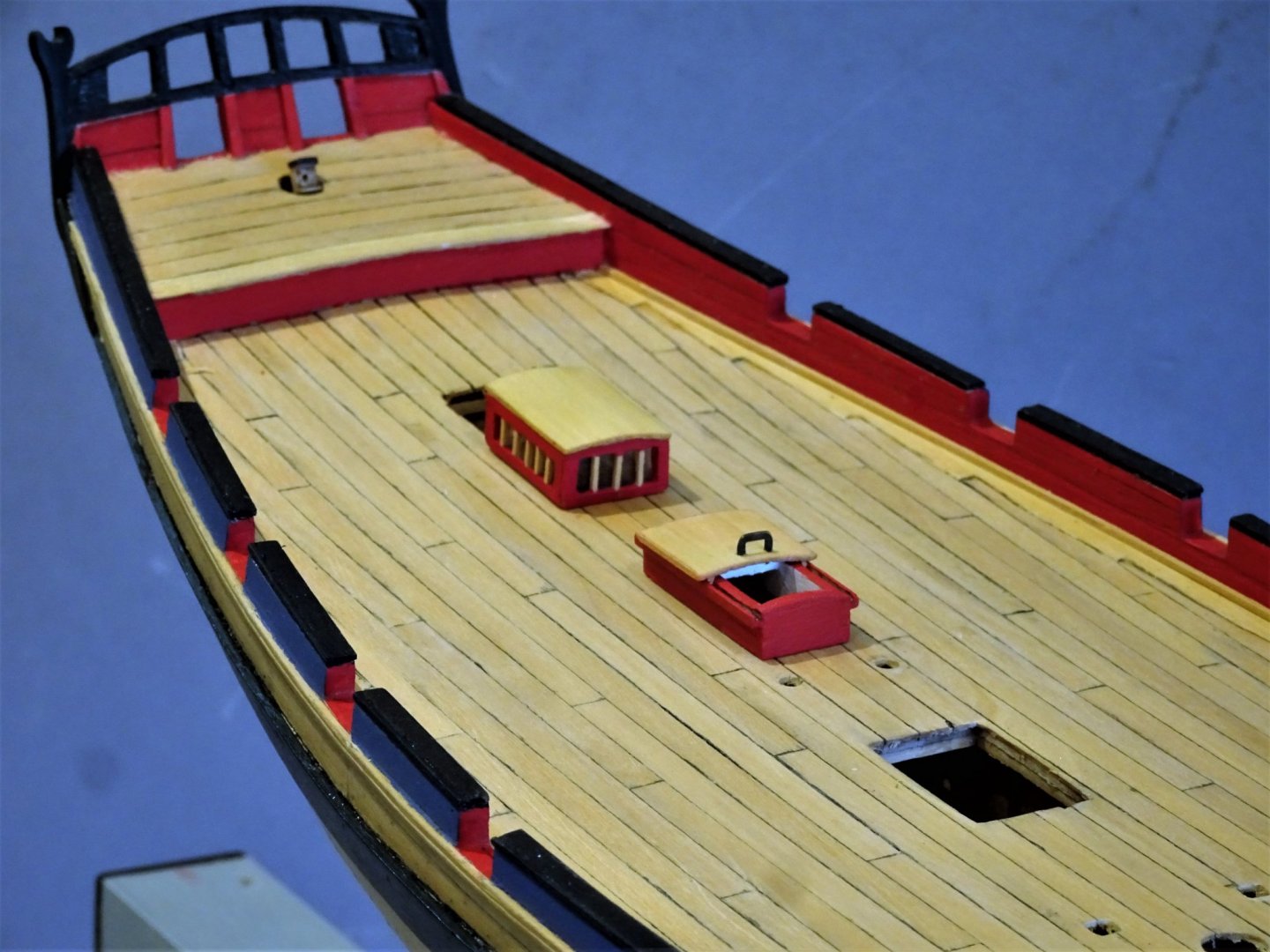
Post 26 Companionways and hatches I will start with the Companion to the Captain’s Cabin, effectively a hinged sky light. This is reproduced in the kit as a brass etched item, with the coamings and head ledges pre-formed in a wood material. These are shaped to reflect the proper joints rather than a simple edge join. The item goes together very well and it is a straightforward assembly particularly for the novice builder. The kit version is as per the drawings in the Goodwin Alert book. A boxy affair with a flat top and glazed square lights. A slight puzzlement is that the kit version has 42 lights contained within the frame whereas the book drawing has 30 lights, which for me looks better, less like a grating. There seems to be as many variations of the Skylight design fitted to Alert as there are models and paintings. Within the Alert book there is a contemporary painting of a model dated 1775 showing a clerestory style skylight. The contemporary model of Hawke (circa 1777) shows the familiar pitched roof glazed sides version. The modern Cole model of Alert has a glazed top but longer, and in a different position. The Irving Kingman model also has a version of the pitched roof style of skylight. I made up the kit version but I tweaked the thickness of the framing to allow for the skylight to sit in a recess rather than just positioned atop the Head ledges and coamings. 3242 Using micro brass tubing I added hinges to allow opening of the light. My preference is for something slightly more interesting than the kit provided item, so I opted for the clerestory style as shown in the painting of the model of ‘Alert.’ The oil painting by Joseph Marshall 1775. The notation in the Goodwin Alert book reads:- An oil painting of the Alert cutter model dated 1775. Various features comply exactly to the modified draught of the Rattlesnake used for the 1777 Alert. These include the squared gunports, the five shroud deadeyes and three backstays chain plates. The painting formed part of the George111 Collection of ship model paintings. This is at variance to the notation in The Science Museum:- who hold the painting, and gives the date as 1755. Perspective view, possibly drawn to illustrate an experimental design rather than an actual plan. a model is known to have been built from design of Sir J Acworth d.1749. - Not part of the series of ship model paintings commissioned by King George III. - Ship is cutter, 6th Rate; eight were in service 1753-1754 Interesting to note that the table on which the model sits, does say ‘Alert’. The paired stern quarter view painting Regardless of these descriptions, the model as painted does look very close in design to the Alert I am modelling. Still I digress. 3241 This is the first attempt of creating the skylight using a bit of Boxwood scrap. My prime concern was getting the scale looking right as I don’t have specific dimensions, but it looks ok to my eye. 3232(2) A view as per Joseph Marshall’s painting. B.E. 26/10/2019
.thumb.JPG.8045508abd9fa56b1c67ec839f6564ff.JPG)


- 335 replies
-
- 23
-
-
- alert
- vanguard models
- (and 1 more)
-
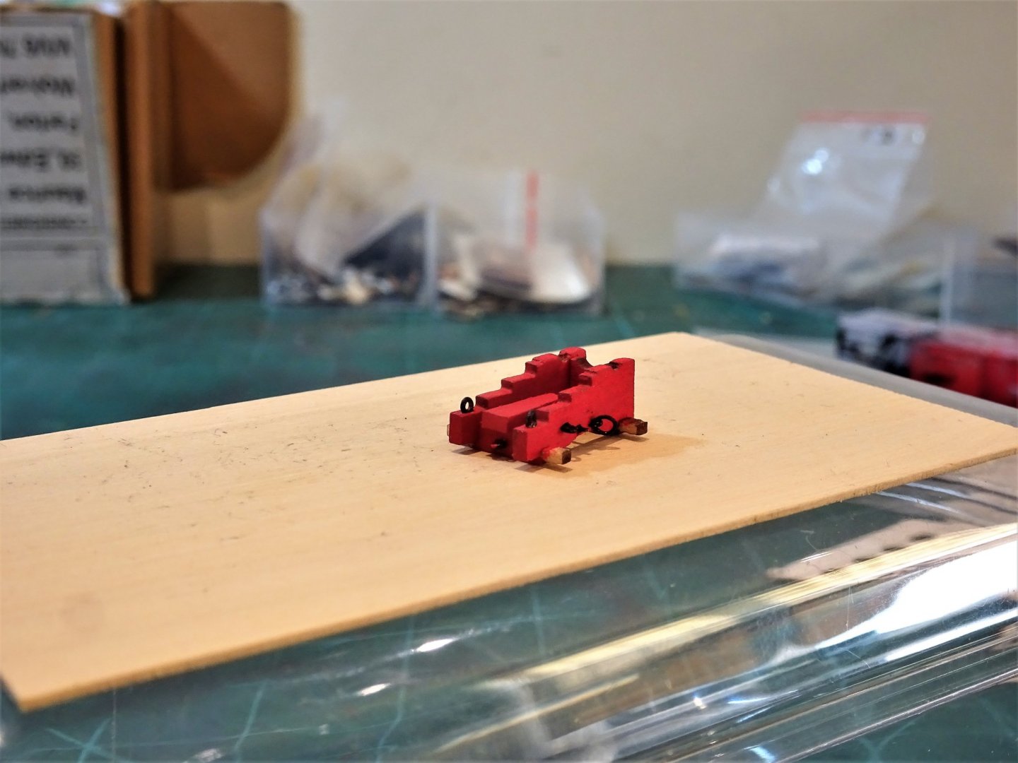
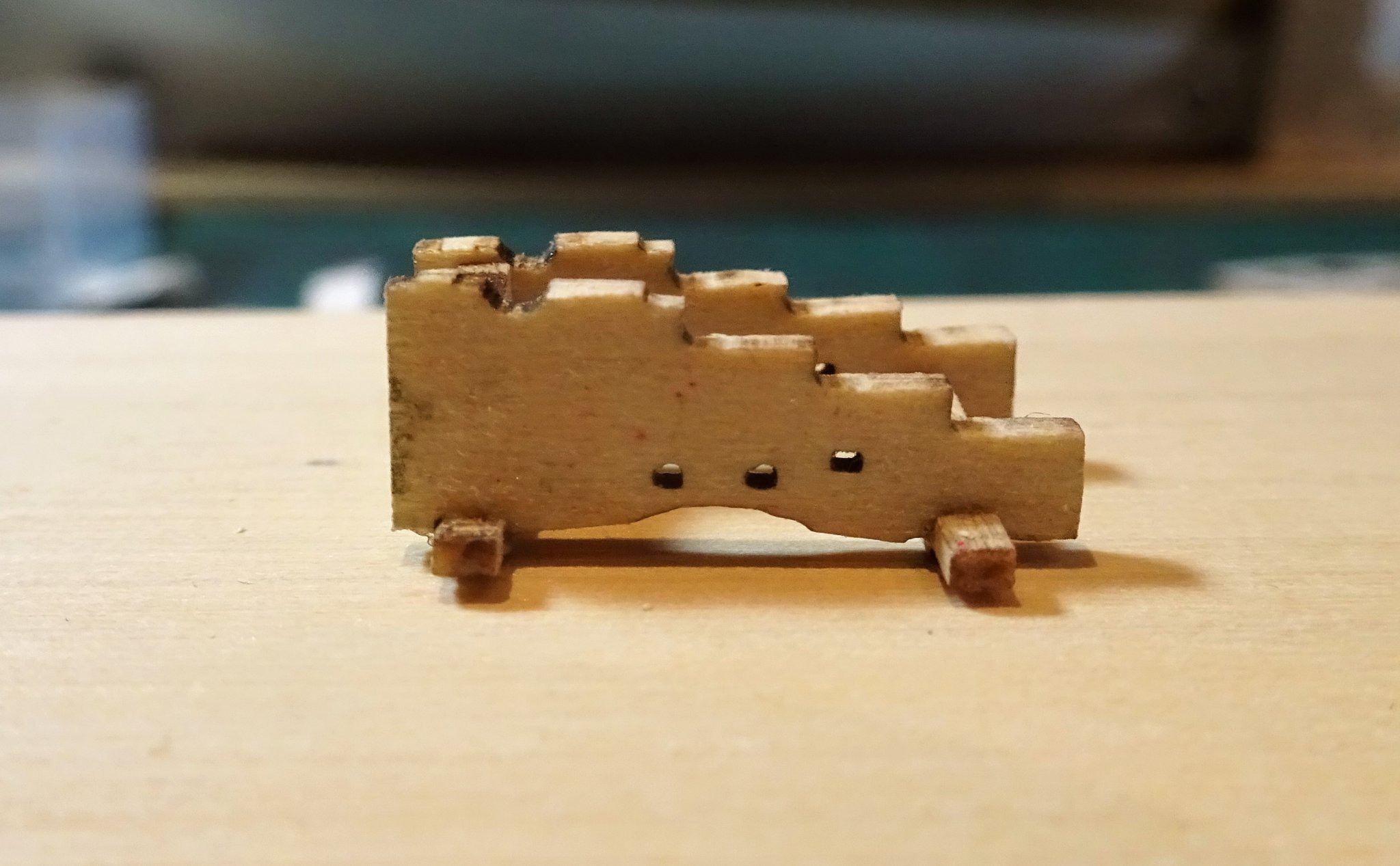
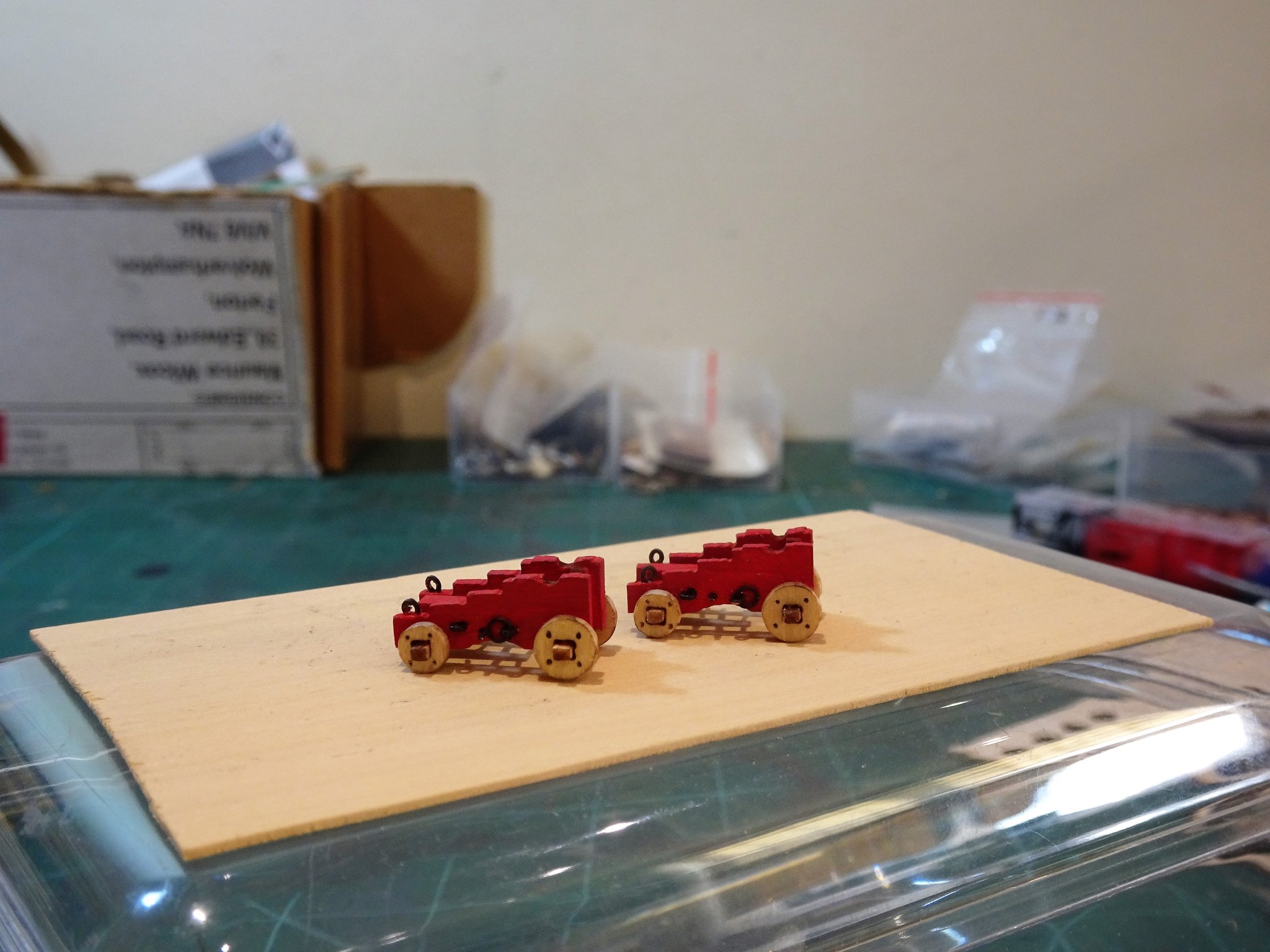
Post 25 Guns Part 2 Moving onto the carriages; The carriage design has been taken from the Alert book and is a good representation for shape. Each carriage consists of five main parts plus the wheels. Cleaning up the parts consists of a light sanding of the laser burn but be careful with the axle pieces they are quite fragile. 3167 I found the carriages easy to assemble, more so than many other examples I have done in the past. I didn’t even need to make a holding jig, just used a barrel to ensure squareness of the setup before the glue dried. There are pre-drilled holes to take the two eye/ring bolts, and the Transverse bolt which spans the two carriage cheeks. 3182(2) The eyebolts and transverse bolt are part of a pe set, but for me the eyebolts don’t work that well looking too chunky for the carriage cheek. 3168 My own preference is to use Amati fine copper eyebolts and rings for carriage fittings at this scale, and I have included additional eyebolts, or hoops as they properly are called, and the ring to carry the breeching rope. 3172(2) Some extra effort is required to make up and blacken twelve sets of ring bolts, and five eyebolts per carriage, but for me it’s worth it. 3170(2) Once assembled a coat of paint is applied and the transverse bolt is blackened and glued into place. 3205 The next somewhat tedious job is to attach all the iron work to the carriages. A puzzling feature for me are the square cut holes in the wheels (trucks) to fit over the axletrees. I expect axletrees to be square but the ends being rounded to fit the wheels. 3009(2) Here the Alert laser set is overlaid with a Syren set, the axle holes are round, and a slight rounding of the axletree allows for fitting. It makes sense to me that the wheel hole is round and the axletree is then carefully rounded to give a good fit. Never mind, for the purpose of the exercise I went with the kit arrangement. 3207 I added the wheel bolts or impressions of them by the simple expediency of marking them using a sharply pointed 9H pencil. On my kit at least the axletree and wheel mortices were not universally a good fit, and I will have to use a fine filler to rectify the issue. This is as far as I am going with the guns at present, there is still a fair bit of fettling to do, and I need to decide on the barrels. B.E. 23/10/2019
.thumb.JPG.754d28c68f277233eafe77cf717bd4b9.JPG)

.thumb.JPG.76eccba4245c7b1175b767a7594941e8.JPG)
.thumb.JPG.89d050bad2dc5a8a173436520979607b.JPG)
.thumb.JPG.a284e073bbc1abbacf24dd7aa71e9b44.JPG)

- 335 replies
-
- 15
-
-
- alert
- vanguard models
- (and 1 more)
-
Thanks Steve, I must admit to looking at the later pics and thinking 'what rubbish planking'.🙄 It is my first attempt at clinker, and I think I could improve on the technique were I to tackle it again, a task I have little enthusiasm for. Still it doesn't look too bad to my eye from 12" or so, but then my eyesight is not what it was.🙁 I always hope the bashing I do on these kits does provide a few ideas for those following on, and doesn't add to their frustration. Cheers, B.E.
- 335 replies
-
- 3
-
-
- alert
- vanguard models
- (and 1 more)
-
Thanks for the heads up Alan I will have a look. I do quite like the Kit guns, but you shouldn't have to work that hard to get them to look anywhere decent. I don't have an issue with either the Syren or RB guns for style, the difference to the kit gun is perhaps the muzzle flare. The Syren and RB guns have a seamless flare that closely follows the design of the Armstrong gun which is period correct, and as shown in the Alert book drawings. The kit gun looks like it has less flare and a reinforcing ring around the muzzle end that looks rather like the style on the model of the Hawke cutter. You pays your money and takes your choice. B.E.
- 335 replies
-
- 1
-
-
- alert
- vanguard models
- (and 1 more)
-
Well done Caroline, cleaned up and fitted out, that will make a nice addition to your Pegasus. B.E.
- 161 replies
-
- 3
-
-
- pegasus
- victory models
- (and 1 more)
-
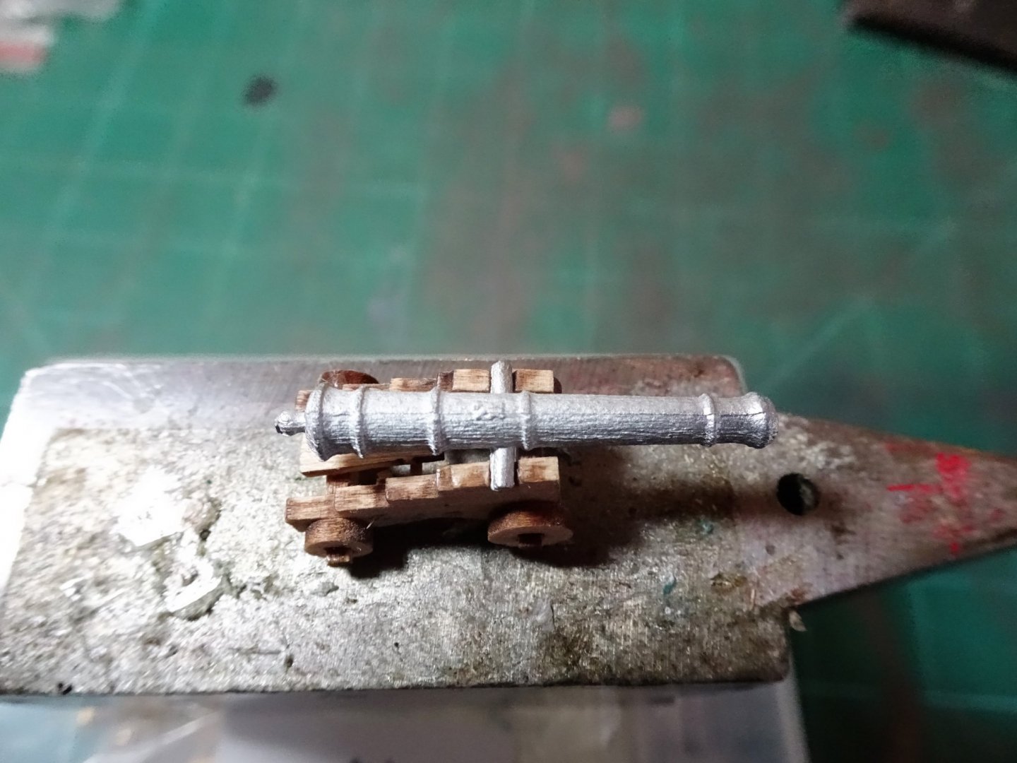
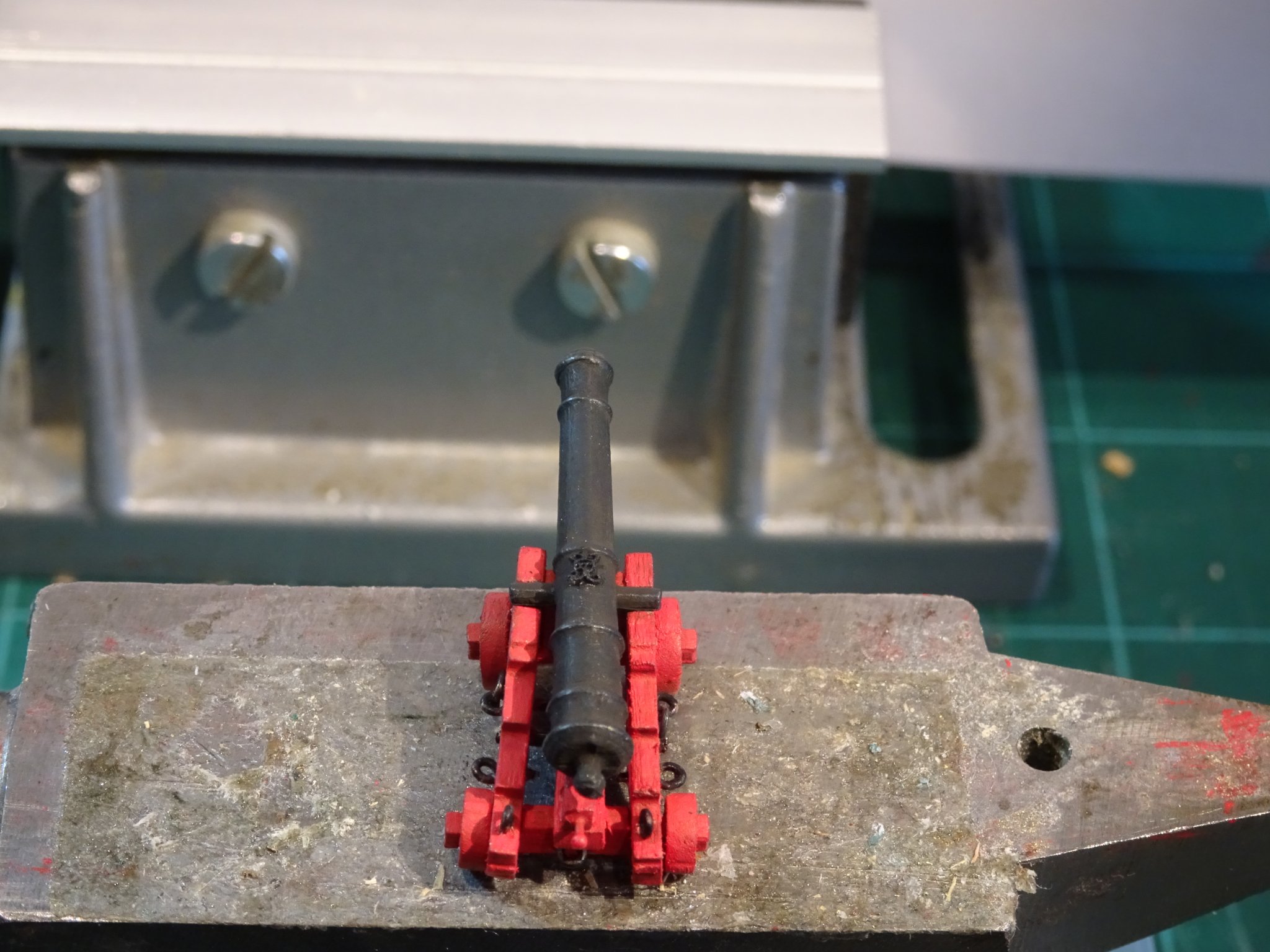
Thank you Kurt and Dave. I did try dowel for the Sheaves, Dave, but also found they split even with a 0.5mm drill, still in the finest tradition of 18th c model making I can always pretend they are bone or ivory.😉 Post 24 Looking at the Ordnance – Part 1 the barrels. The white metal guns do have a nice scale look about them but leave something to be desired in terms of finish. Mine had prominent seams, and there are noticeable longitudinal striations along the barrel, almost like a timber effect. 2995 These are apparent to the naked eye and not just the macro lens. It will prove very difficult to get a clean surface, my attempts using wire wool and files were frustrating with the danger of affecting the reinforcing rings around the barrel and the already indistinct Royal Cipher. 3043(2) The barrels did however respond well to blackening using Casey Brass Black. 3047 I did happen to have a set of Chuck’s excellent little fibre Royal ciphers, the smallest of which fit perfectly on the barrel. There is an alternative Syren barrel in Brass with a length of 11/64” (29.75mm) This is a good match for a six pounder at 1:64 scale. I did check the availability of a resin version with Chuck but these are some time away, pity because his already produced versions are superb, complete with clear cipher and touch holes. 3051(2) Here a Syren 11/64” barrel on a kit carriage. 3053 Here the same gun on an incomplete Syren carriage. 3162(2) From left to right; Blackened white metal Kit gun, Brass 11/64” Syren gun, Blackened Brass RB 29mm gun, Blackened Brass RB 32mm gun, Brass Syren gun on Syren carriage. 3159 From a different angle, at this point the carriages are incomplete. 3161 3157 I do like the proportions of the kit guns, but I can’t live with the quality of the white metal. Chris has since posted that as an upgrade to the white metal guns, cast resins versions will be available. I would suggest that these be made standard even at some extra cost to the kit. I can’t imagine a high satisfaction level from modellers with the metal versions, and for me the shortcomings of the white metal guns do damage the kit quality image. The Brass Syren guns are beautifully made and a set for Alert will currently cost $46.50 for the barrels and $18.00 for the Boxwood carriages if required. RB Models of Poland also produce very nice brass guns, I used their 32mm versions as the six pounders for my Pegasus build. These look a little heavy on the Alert carriages, but their 29mm guns are a good match and very reasonably priced at around £10 delivered to the UK for a set for Alert. Before I make a final decision on the guns I would like to check out the Vanguard resin upgrade and will buy a set if they become available, otherwise it will be between the Brass Syren or RB guns. In my next post I will be attending to the carriages. B.E. 20/10/2019
.thumb.JPG.95ff46a9f2d692687e9c4af44ae31ef3.JPG)

.thumb.JPG.1660c459c3282fc869ef31533827cffc.JPG)
.thumb.JPG.69e8bfa1e77f03ad5f8d0687b7096192.JPG)


.thumb.JPG.3c3fe6a8cad09f14074256fd46c7c6d1.JPG)
- 335 replies
-
- 17
-
-
- alert
- vanguard models
- (and 1 more)
-
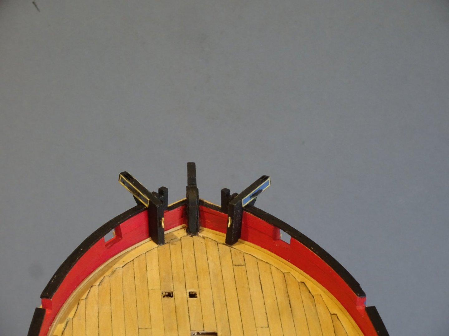
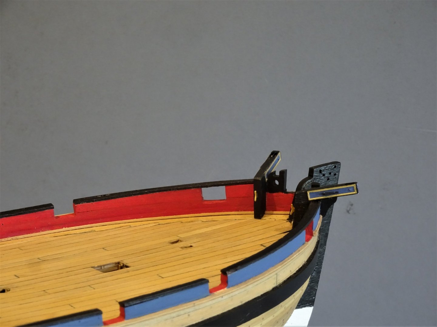
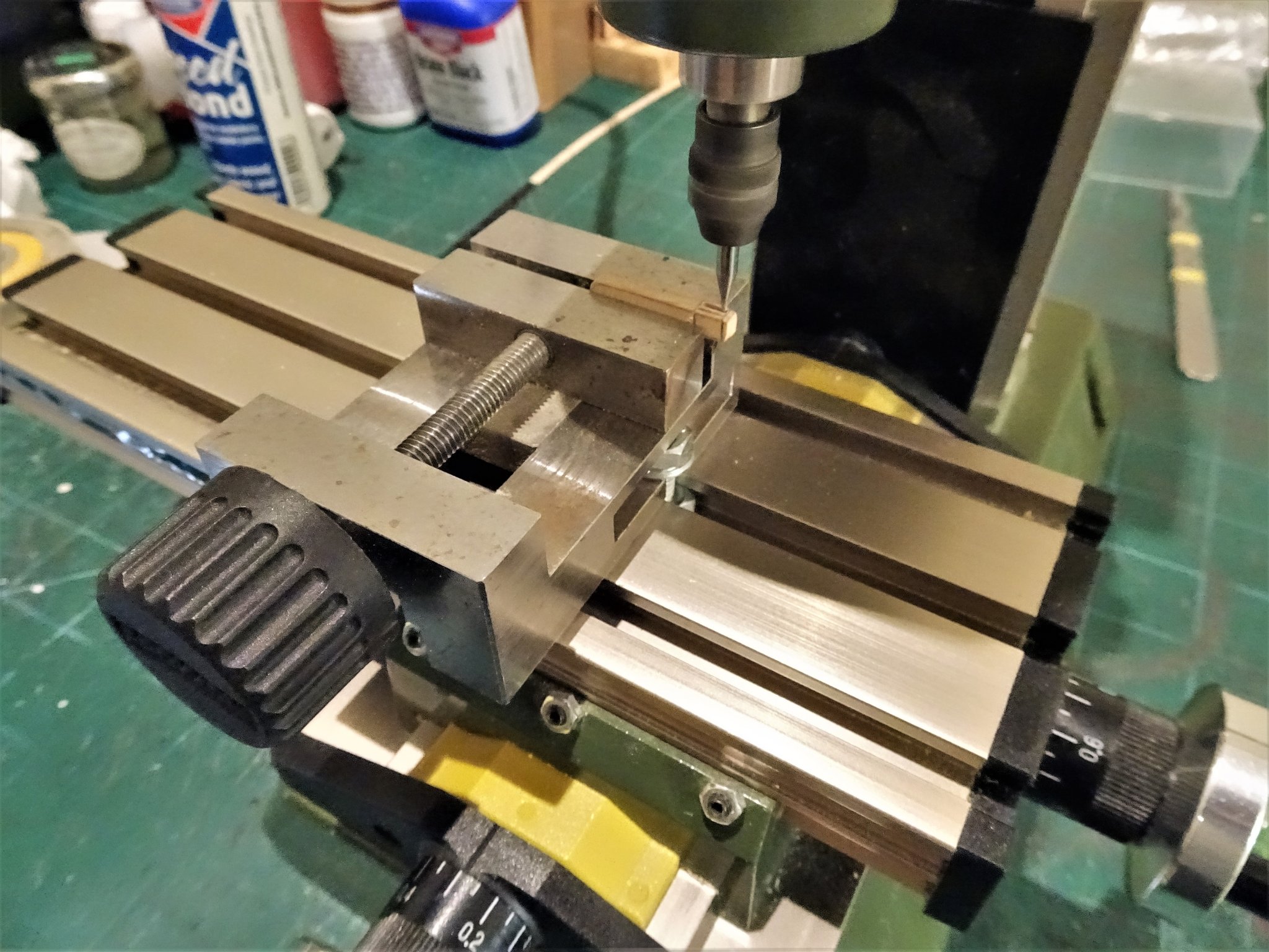
Post 23 Catheads and hawse ports The Catheads are one piece and pre-formed out of some 3mm wood, and have additional brass etch decoration and a pe cleat. There is no reference to sheave holes in the Cathead, but I’m not sure of the wood type or whether it would stand up to slotting. I decided to cut new Catheads out of 3mm Boxwood and cut a double sheave in the end. This will allow for the rigging of a Cat Block and hook, something I like to see on a model. 3066 This is where the Proxxon mill comes in, very difficult to cut these slots by hand at the scale involved unless perhaps if saw cut are made in the outboard end which is then capped. 3091(2) The sheaves are cut from Evergreen Plastic round section and held in place with brass wire. 3147 I did use the brass etch cleat for the Cathead stopper and the decorative border as these would be difficult to replicate at the scale. The border has a very fine profile on it, which I decided to preserve by coating the brass with only very flat matt varnish. The kit also includes a Cathead decoration of a Crown representation. There is no evidence that ships of this period carried such a cipher; Known decorations consisted of Lion/cat faces (hence the name) Star motifs, Fouled Anchors, and simple geometric mouldings. 3142(2) I replaced this with a Fouled Anchor motif. 3140 I added a cleat on the upright to secure the Cat tackle. 3144(2) I used the kit provided Hawse Port parts. 3134 The final addition to the Cathead set up are the support brackets. 3150 3152 3148 I will next have a look at the guns. B.E. 19/10/2019

.thumb.JPG.7ea93ba14776a6afd4d56661612c0b56.JPG)

.thumb.JPG.1a83c86b997aac5c4a30444b32a6469e.JPG)
.thumb.JPG.cee86c6442eca271112f264dc5eb3fe3.JPG)

- 335 replies
-
- 23
-
-
- alert
- vanguard models
- (and 1 more)
-
170 are called Crowsfeet, they were used to prevent the topsail getting caught beneath the Main top. E17 is called a Euphroe, it is a wooden block used to rig the Crowsfeet. B.E.
-
I see you’ve not wasted any time getting started Caroline, it certainly has the look of a Pinnace, looking forward to seeing how it works out. B.E.
- 161 replies
-
- 2
-
-
- pegasus
- victory models
- (and 1 more)
-
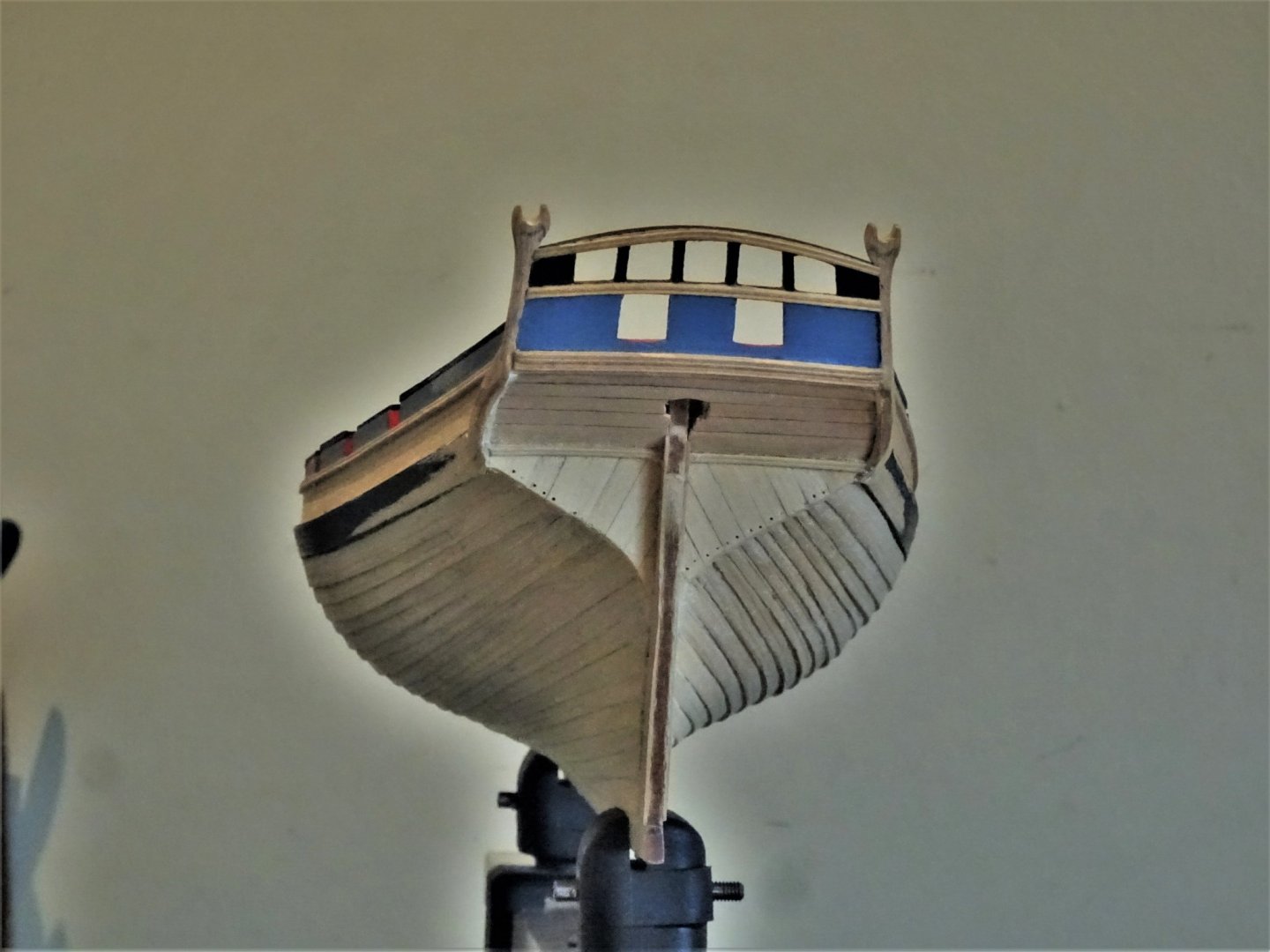
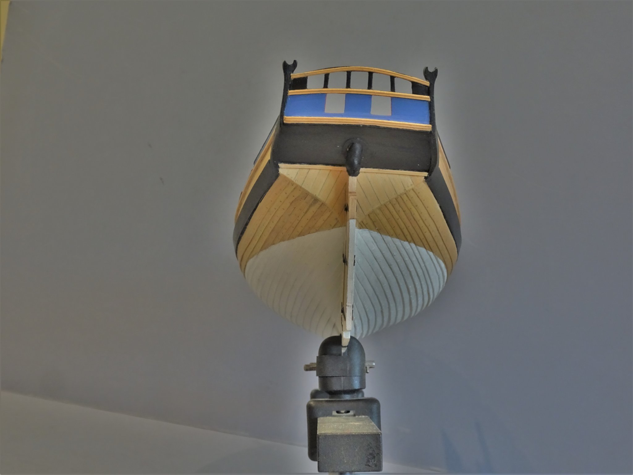
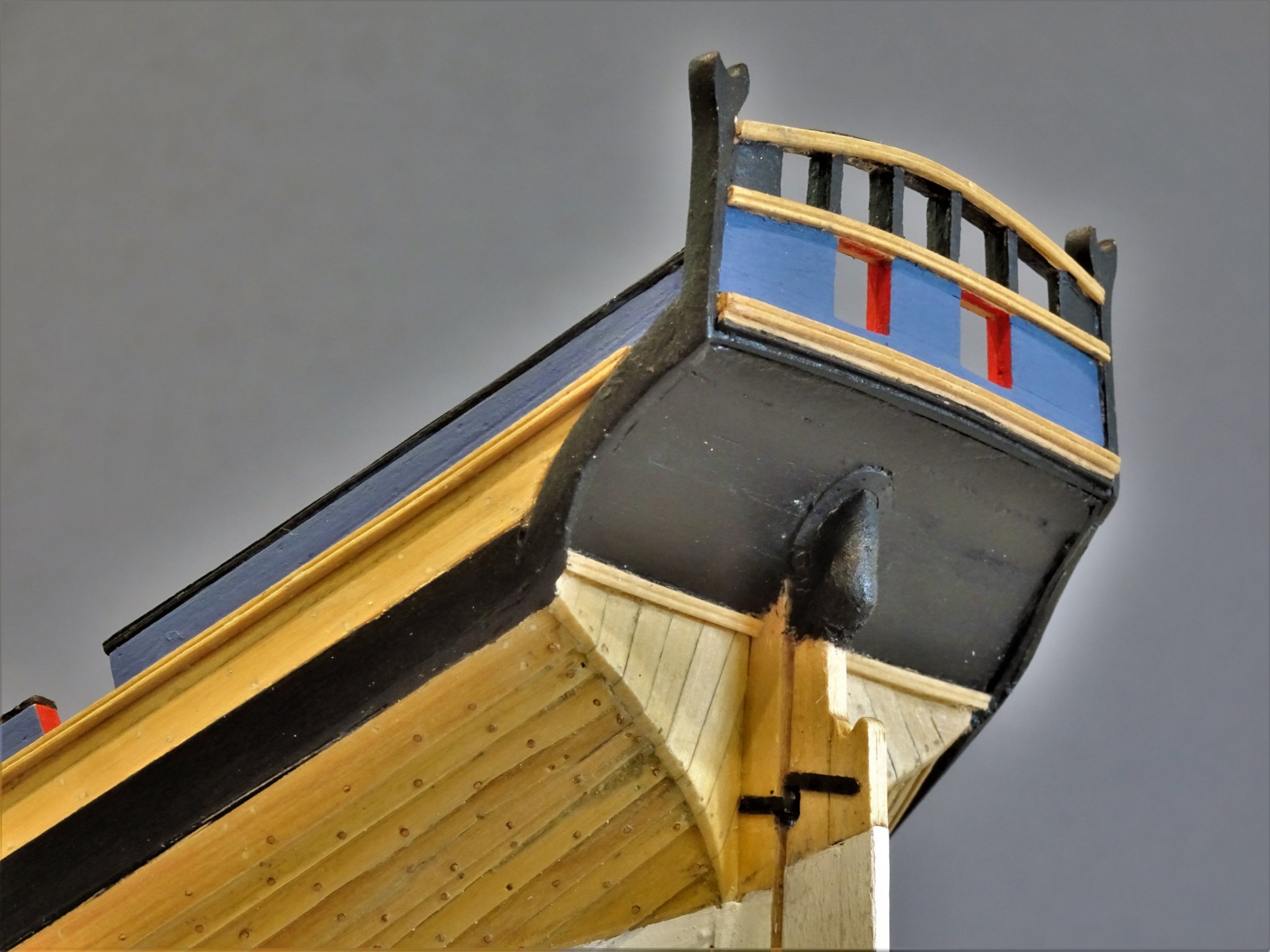
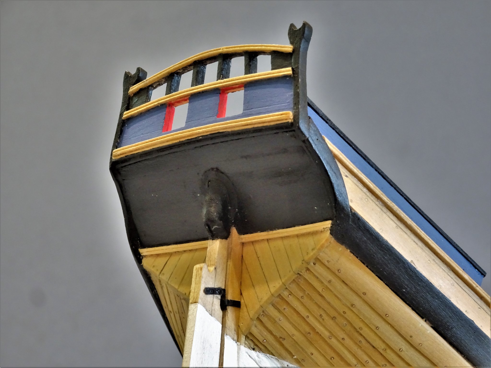
Thank you Dirk, Nils, and Rusty. 🙂 Post 22 Looking at the rudder I prefer to fit the rudder at this stage of the build while I can still fully manipulate the hull before any of the deck fittings are in place. The provided kit rudder is good for profile but does need pre-fit fettling. No mention is given in the instructions that ideally it should taper somewhat from fore to aft and from the hance to the base. There is also a chamfer or bearding on the forward edge of rudders. 2929(2) I have scribed the line of the Back piece of the rudder Those who may wish to enhance the rudder could do no better than have a look at Chuck’s online instructions for his Cheerful kit (Chapter 11) or his own log (p25) 2926 There is a lot of trial fitting of the rudder. For the Gudgeons and Pintles the kit provides pe parts with a simplified arrangement that allows for easier fitting but does not allow for movement in the fitted rudder, and looks slightly odd to those with an eye for the proper set up. I happen to have parts of Chuck’s Pintles and Gudgeons kit left over from my Cheerful build which even at 1:48 scale can be tweaked to suit Alert. I applied this system and it does work, allowing movement of the rudder and unshipping. 2955 Fitting the gudgeons from the Syren kit. 2954(2) A length of wire is used to align the holes for the pintles. 2958 Fixing the pintles to the rudder. 2961(2) I also used the fibre board straps from the Syren kit, which if anything look more in scale on Alert. With everything in place small blobs of pva are used to represent the bolt heads. The final touch to the Rudder head is the addition of the ‘iron’ hoops. These are represented by my old standby slivers of heat shrink rubber tubing. 2964(2) With the rudder completed the tiller can be added. This is scratched from a scrap of boxwood section. A piece of stiff wire connects with a push fit to the rudder head. A question arises in relation to the length of the Gudgeon braces. The kit indicates they are fairly short and contained within the width of the stern post, and this is the arrangement on the Admiralty plans. This is also mostly the case in the Alert Book drawings, but the General arrangement drawing on p52 shows them extending onto the hull, as do the photo’s of the contemporary model of the Hawke circa 1777. The lower gudgeon straps of Cheerful also extend beyond the stern post. 2988(2) I have opted for the short version given that it reflects the admiralty plans. 2984(2) In rudder hanging the aim is to get as narrow a gap between rudder and stern post consistent with rudder movement. 2983(2) The subtle taper of the rudder is apparent in this photo. 2980(2) Lemuel my Helmsman confirms the fit of the tiller before final finishing. Next up – a look at the ordnance. B.E. 13/10/2019
.thumb.JPG.0f7ec4943a6799e25285dcd792c5e0f7.JPG)
.thumb.JPG.cbefe890887be37f8869ce2d2e290fab.JPG)

.thumb.JPG.94448e8cc8caef46160e2b8f420ad2f3.JPG)
.thumb.JPG.ccab2abd6f1a16e38c391b236702a2bb.JPG)
.thumb.JPG.d20b9788c39d44f7882b31e059c26f42.JPG)
.thumb.JPG.df5f0e8d9b3d1dcd71241f5c51251857.JPG)
.thumb.JPG.793e76e373a1ade9c2bd7f7983d98c1d.JPG)
.thumb.JPG.ae2f4ebcfb0d3918cd659bddedc71642.JPG)
- 335 replies
-
- 20
-
-
- alert
- vanguard models
- (and 1 more)
-
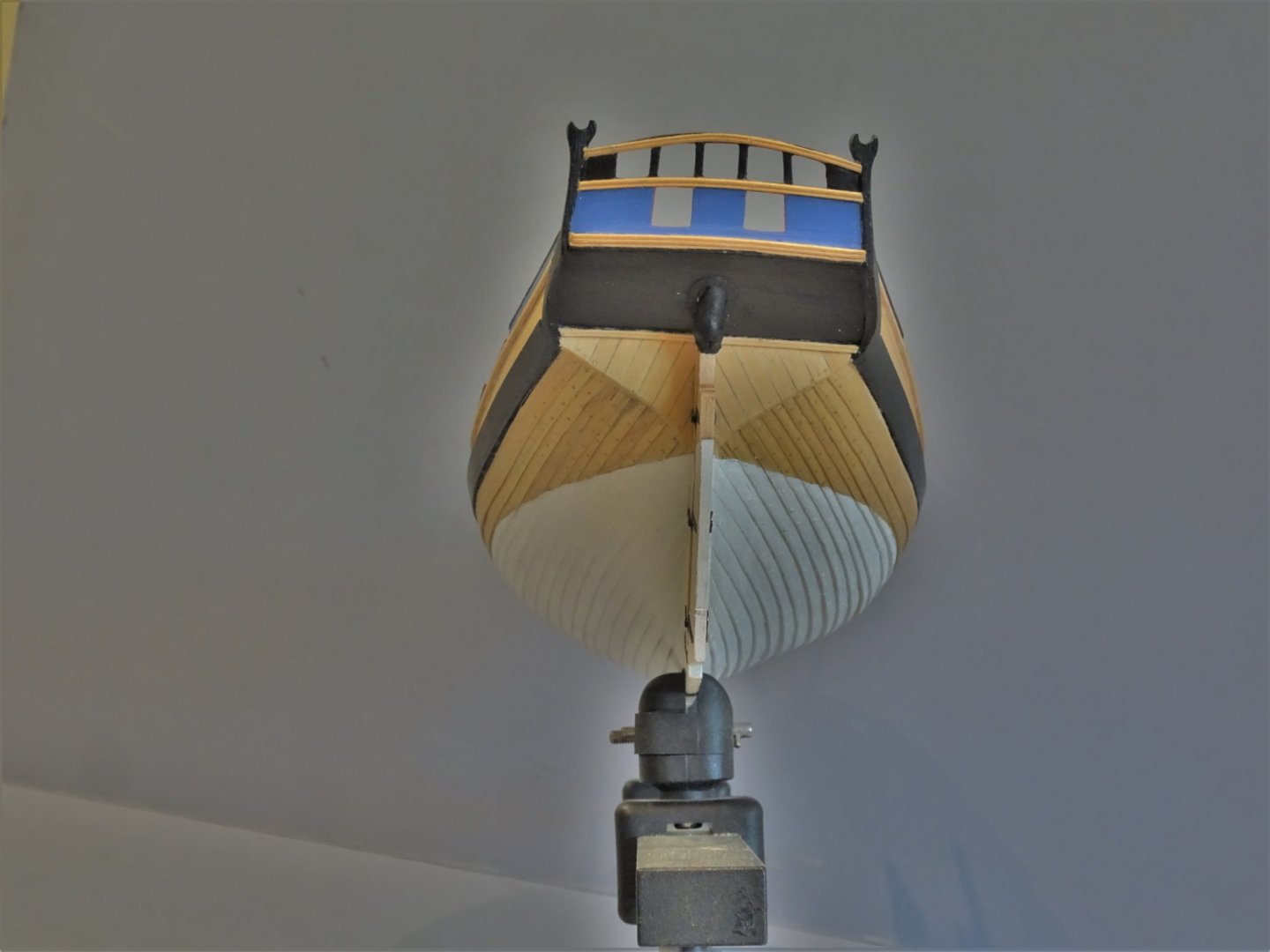
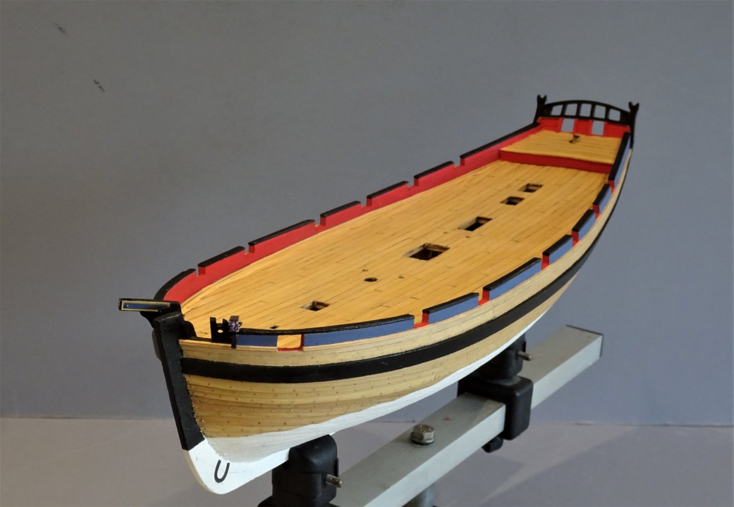
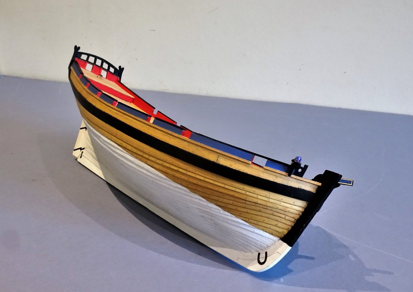
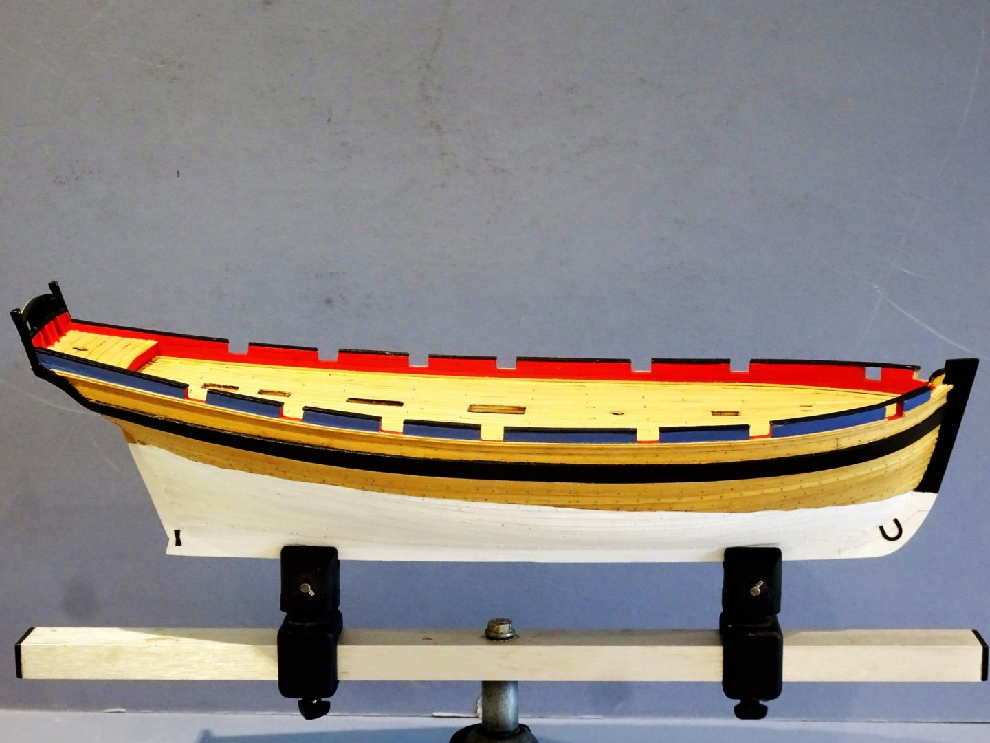
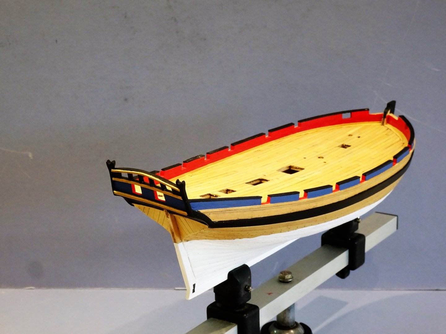
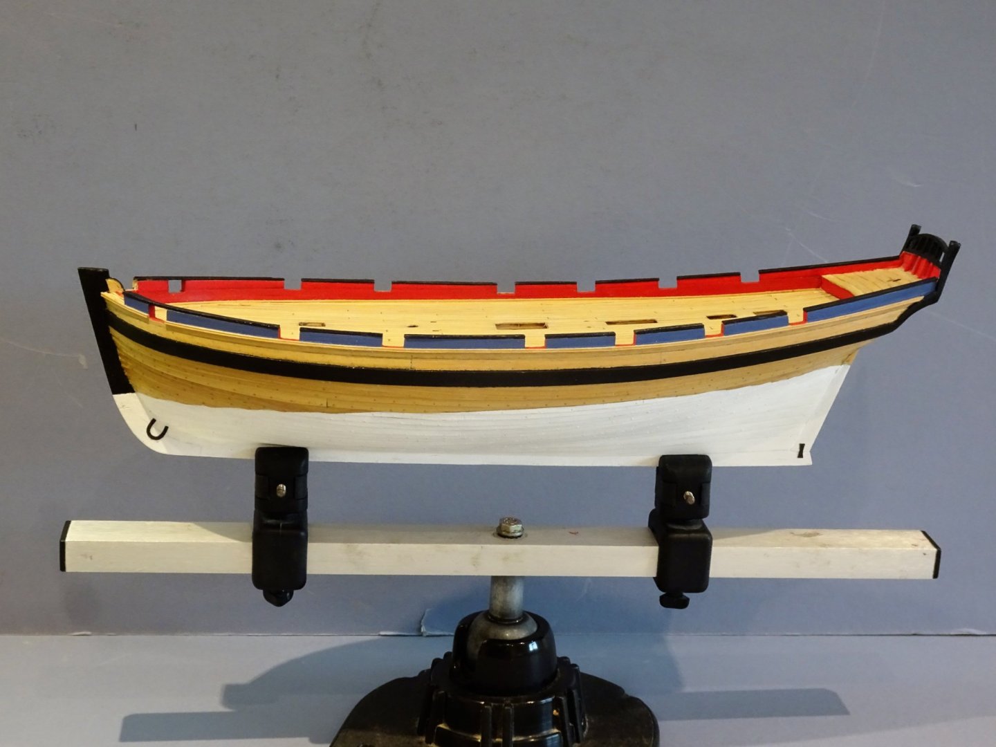
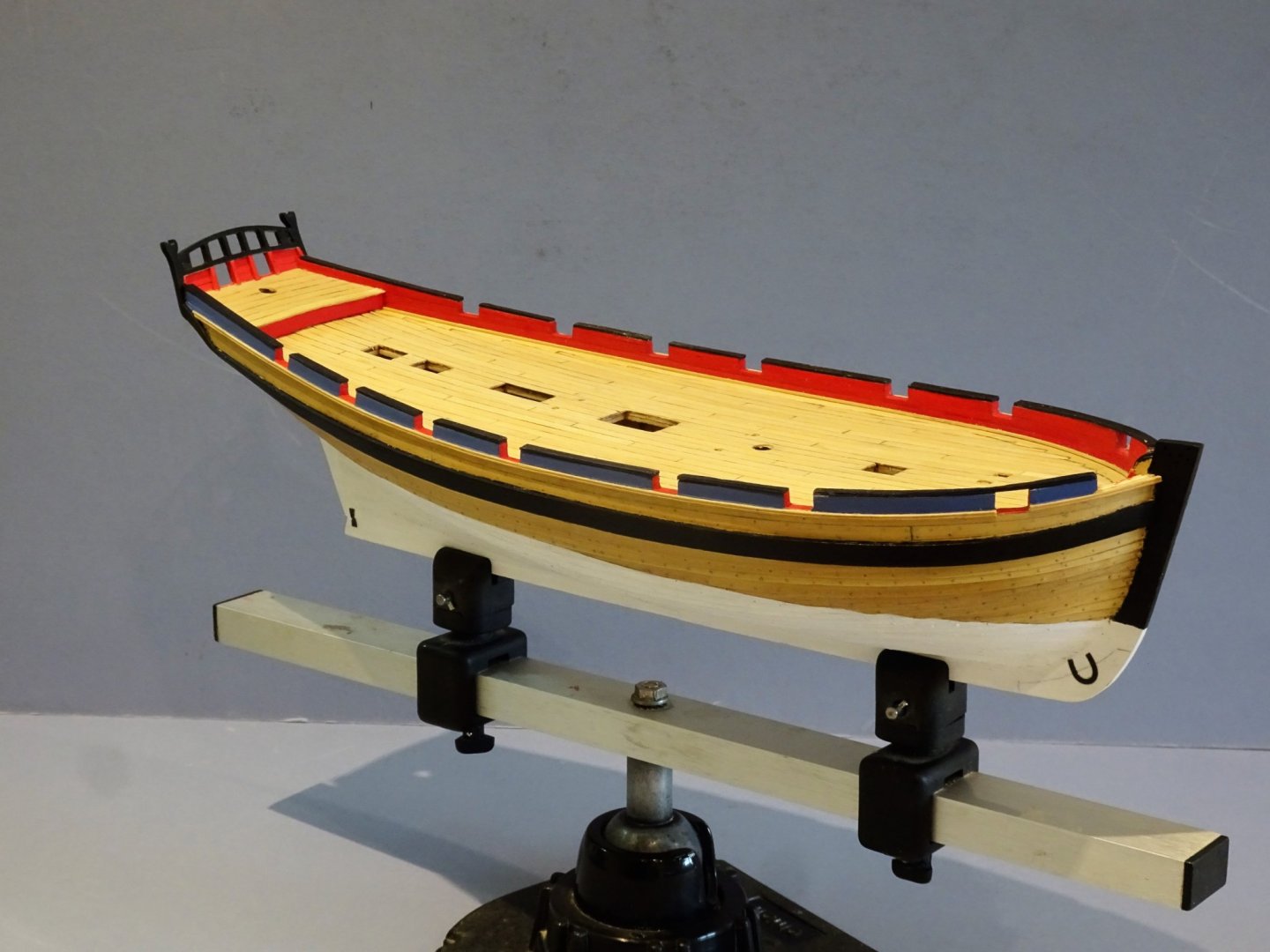
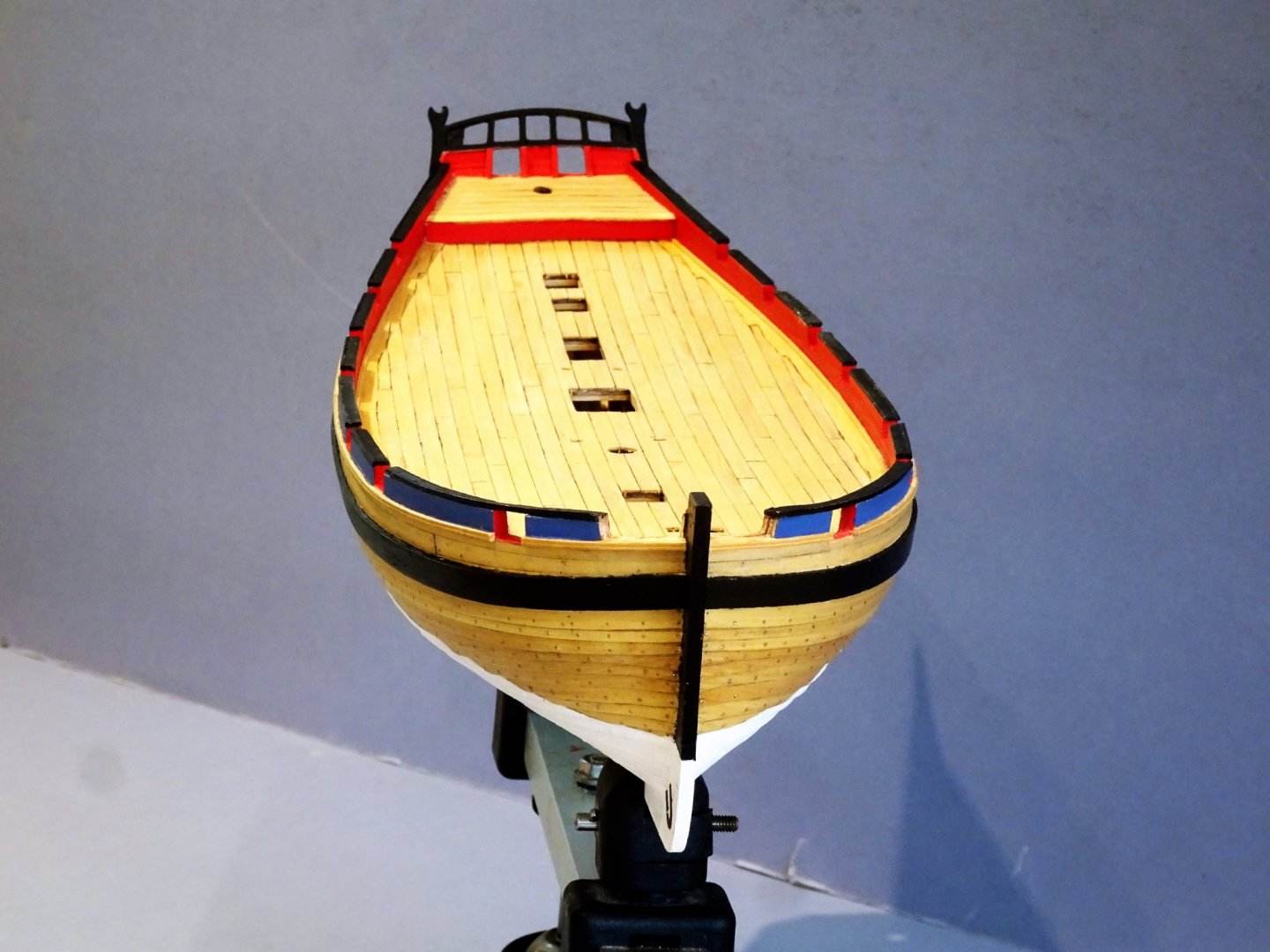
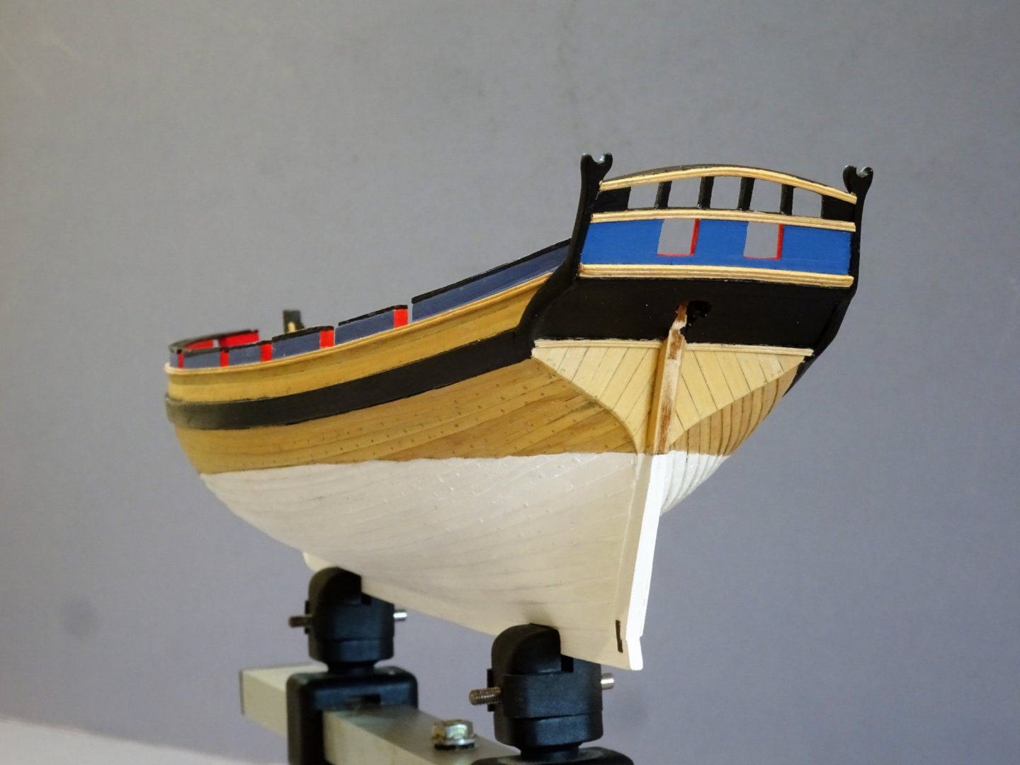
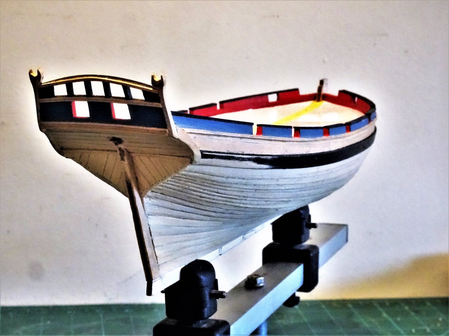
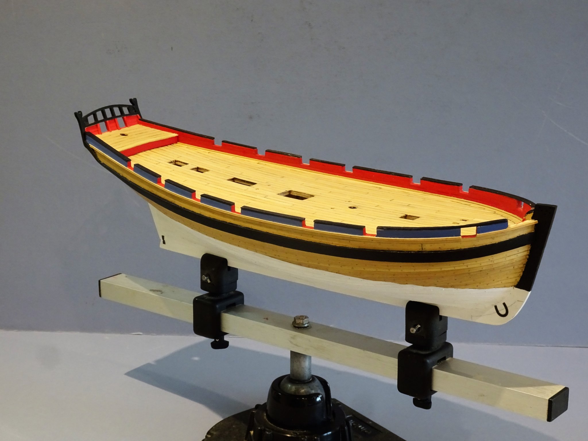
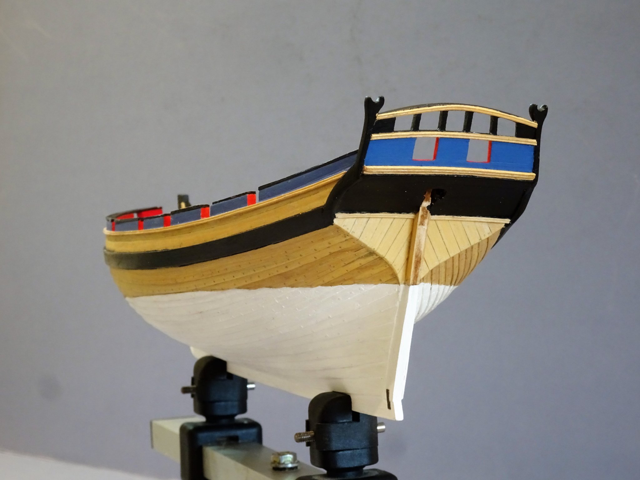
Thank you Nils and Dave, and to those who have looked in on the build. Post 21 Finishing the hull – part 2 With a few coats of white paint applied to the lower hull and being more or less satisfied with the top line, I could at last get some poly on the topsides above the waterline. I quite like the combination of varnish and white paint on a model. 2951 2947 2943 2942 The inevitable stepped waterline is clearly apparent in this shot. 2953 2941 2940 2939 2938 2936 2935 2934 So after four months, and at this point I can review the changes made to the build thus far. The most obvious is of course the clinker planking using thin Boxwood planks cut from sheet material. Clinkering is not an easy option, can’t be done with kit supplied timber, is time consuming, as each plank is individually spiled, and then there’s the application of copper ‘bolts’. My approach has been fairly simplistic but at this scale I think it works even tho’ I would have wished for better execution of the work in places. Above the wale I used Boxwood planking rather than the supplied Pear wood. Scratch made Side counter timbers and extensions to the boom crutches. I really didn’t like the two piece add ons in the kit arrangement which to my eye looked unconvincing. 1 I have also tweaked the internal counter to better reflect the counter timber arrangement. Enhancements to the hatch openings by the addition of carlings. Creating a lower deck view thro’ the openings. Pre-formed Capping rails replaced with Boxwood strip with thinned down width. Sheer and Counter rails replaced with Boxwood strip scribed with a pattern. I am now starting to feel a little happier about the build, altho’ I still wish I had replaced the stem piece with Boxwood. Moving on to the Rudder. B.E. 11/10/2019


- 335 replies
-
- 21
-
-
- alert
- vanguard models
- (and 1 more)
-
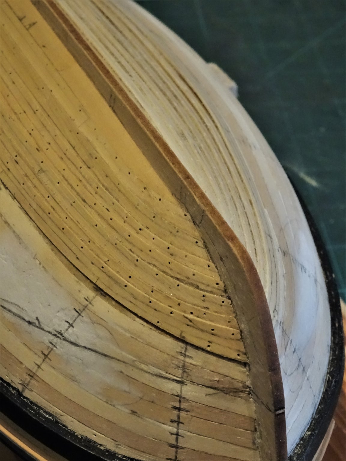
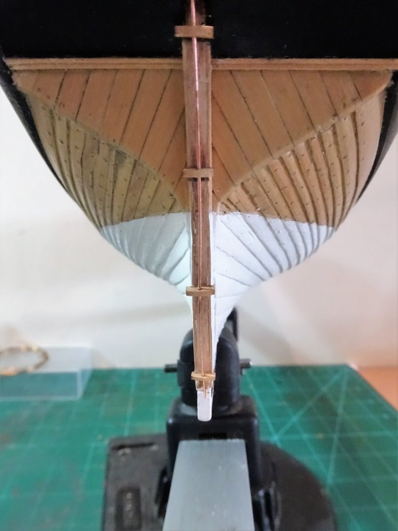
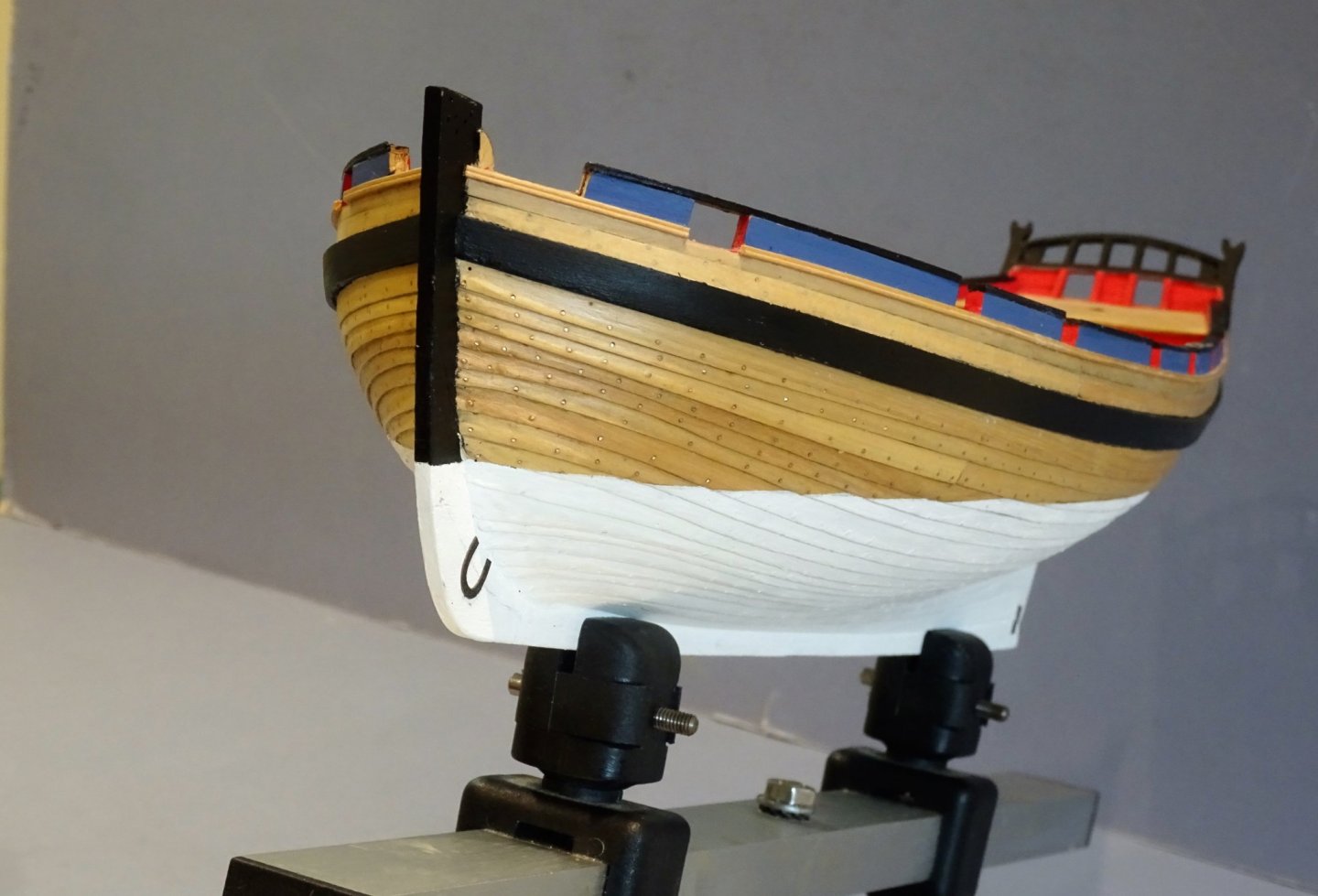
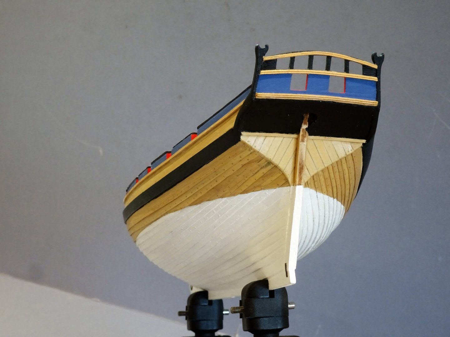
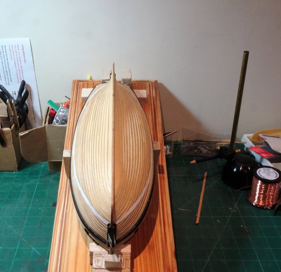
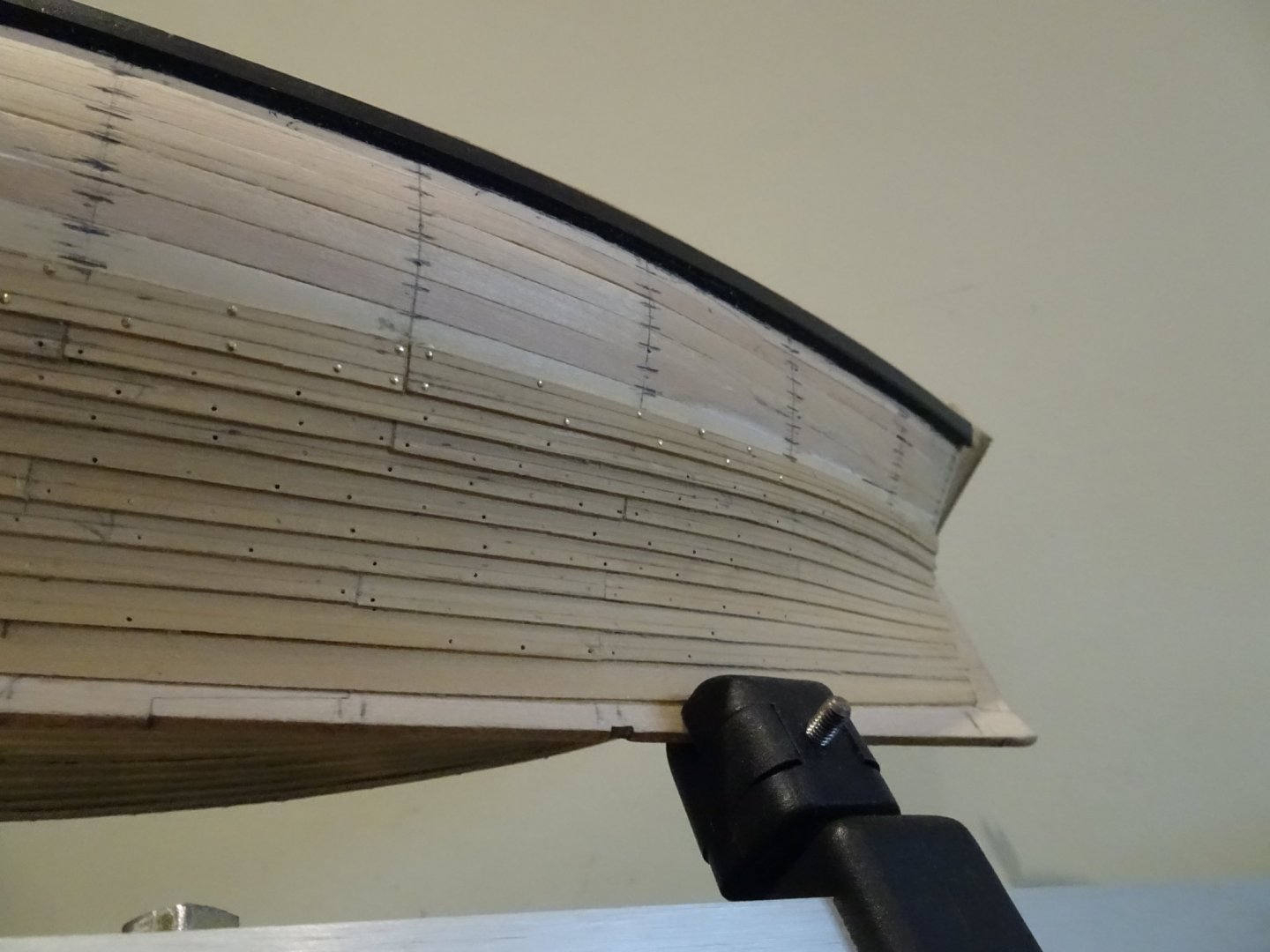
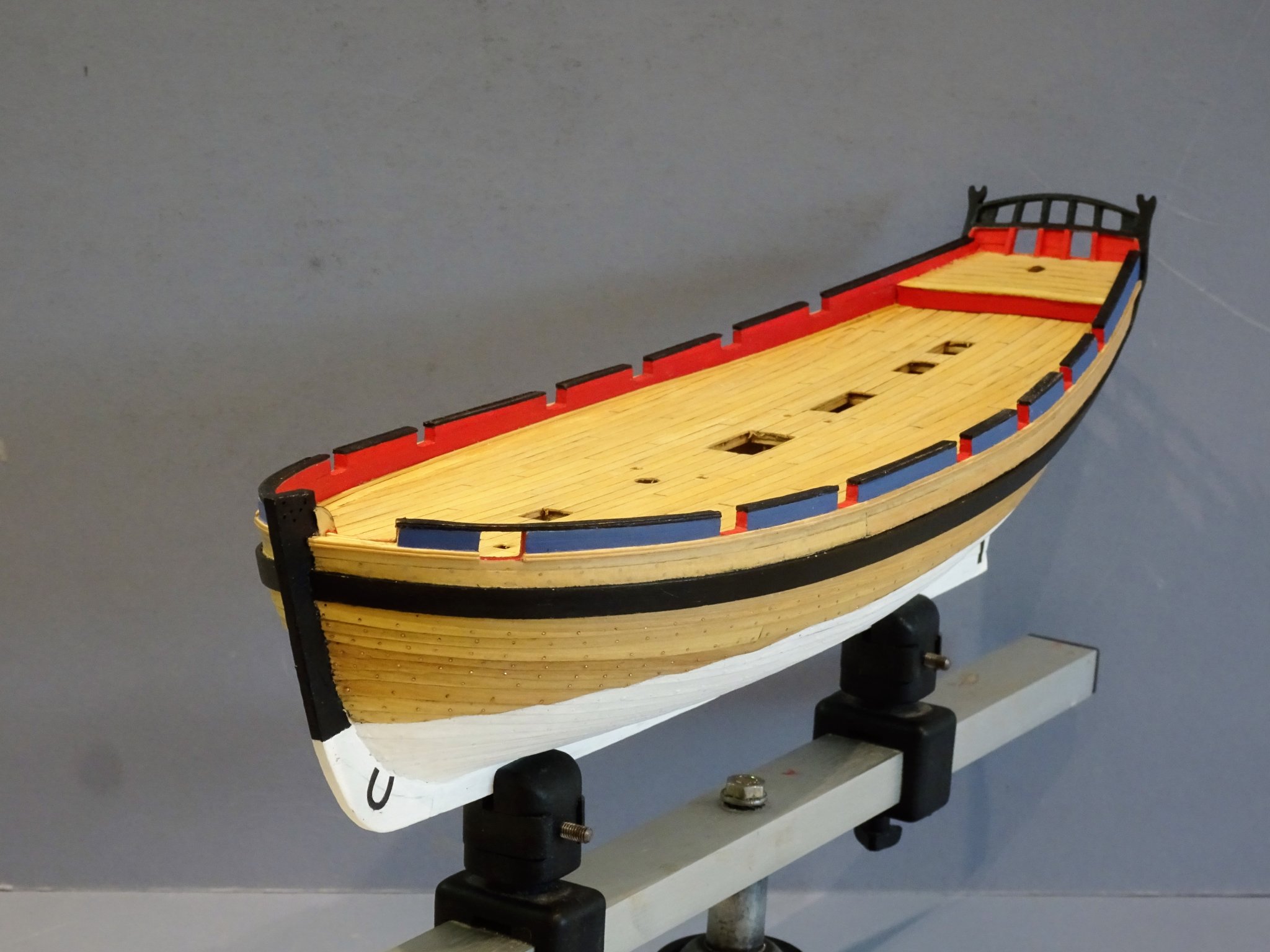
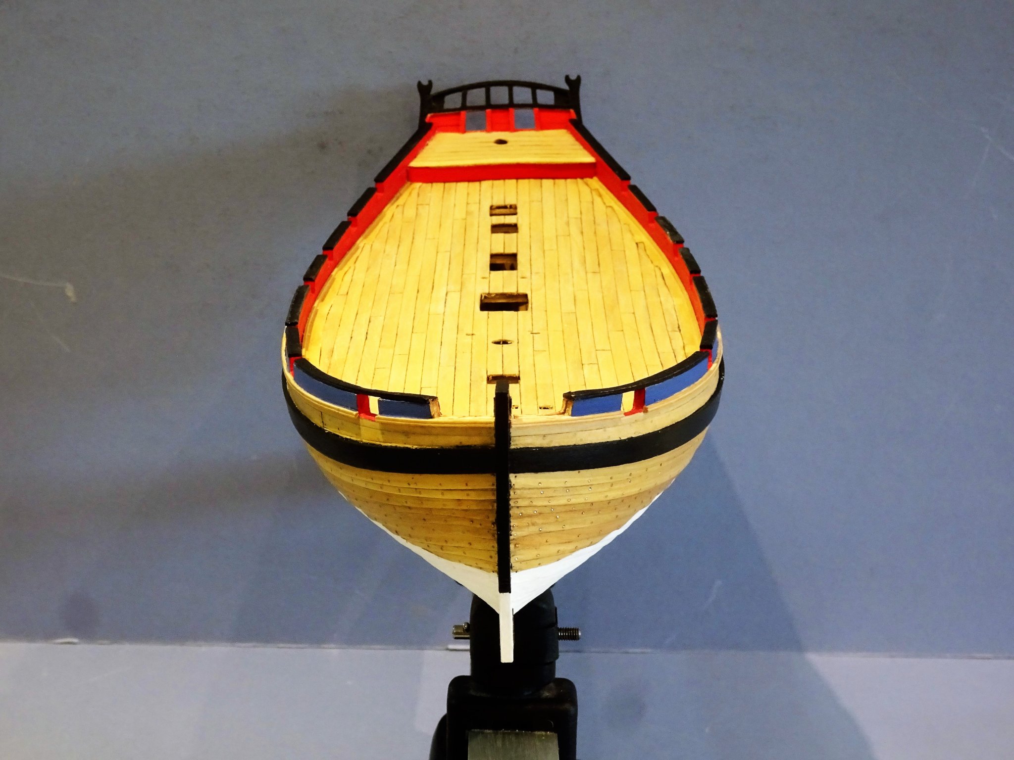
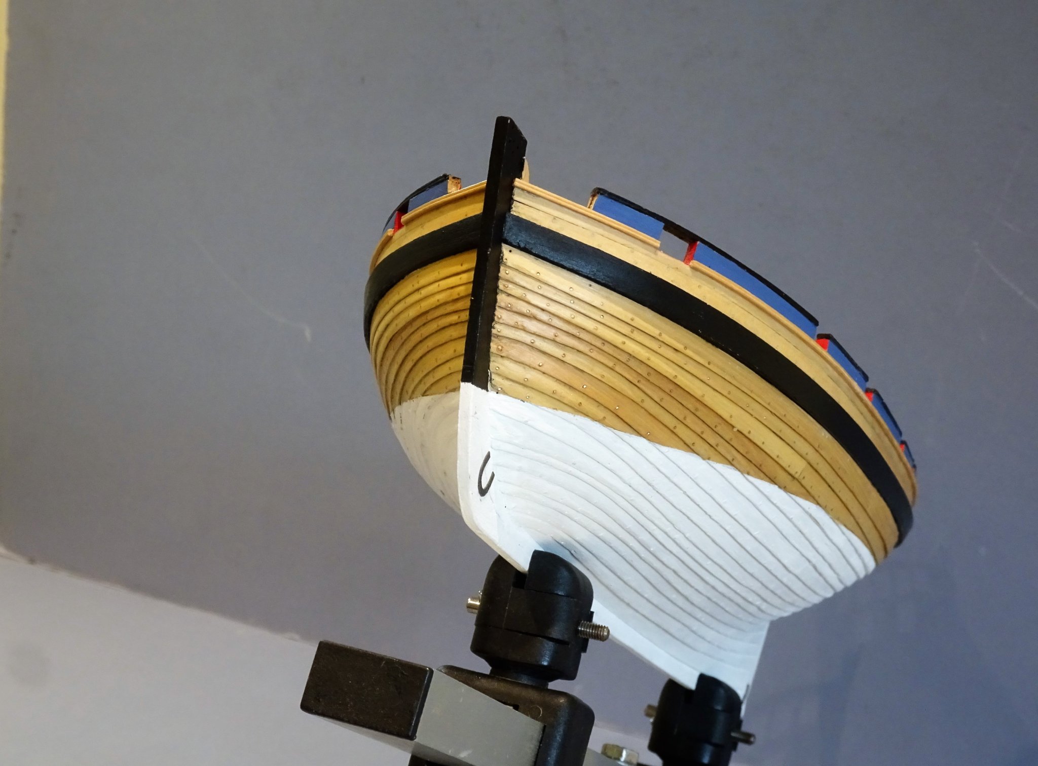
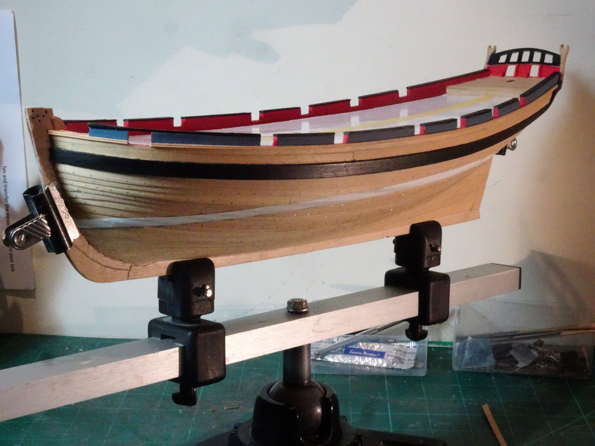
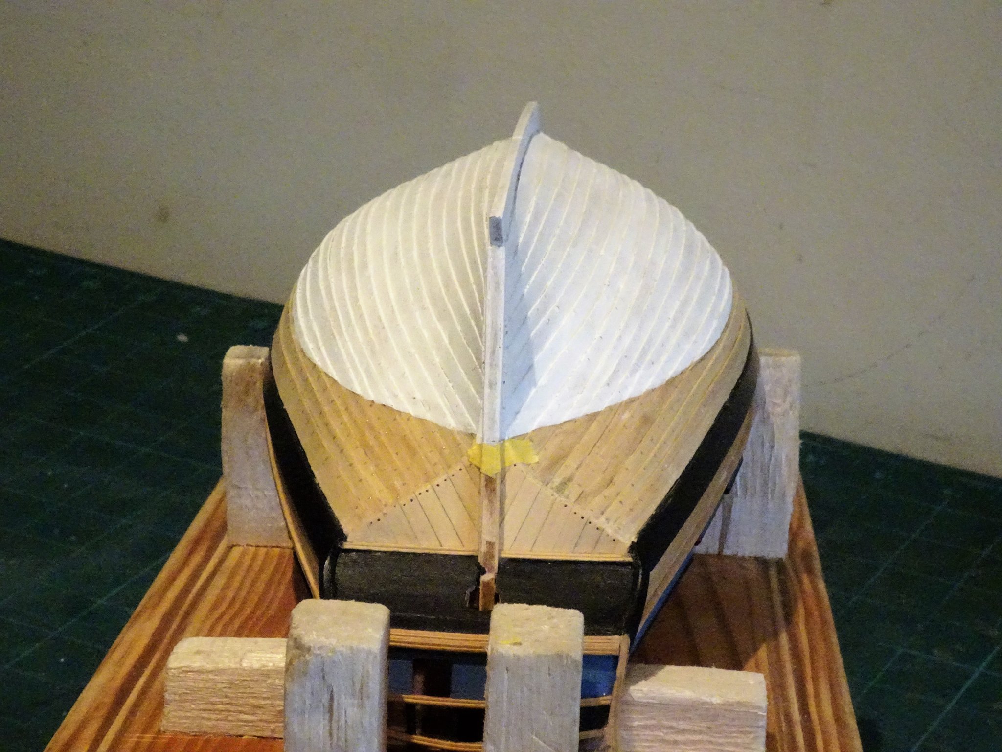
Post 20 Finishing the hull This involves scraping the boards to clean and fair them into the bow and sternpost, and then drilling the estimated 2500 holes for the securing bolts. I have taken the measurements for spacing from the Alert book, which work out to a 7mm spacing at scale. I am using 24swg 0.56mm ø copper wires to represent the bolts. 2814 A week of fairly concerted effort sees the hull bolted. With this done the tricky waterline question remains. Not one of my favourite jobs and the clinker is an added problem. How do I get an effective waterline marked? In marking the waterline, it seems best to me, having set the level at the bow low point, to start at the centre high point of the line and work fore and aft. That way the line runs with the lap and the pencil is not thrown off by the ridges. 2815 Once the line is marked, Tamiya tape for curves is run along the lines to check by eye that both sides look even. 2819 I’ve never found that this Tamiya tape works particularly well, doesn’t seem to have as much grab as the yellow version. 2824 Altho’ I’m satisfied with the line of the waterline, inevitably I’m not going to get a sealed line to paint along, and my main concern is that the waterline line looks good with the clinker effect at model scale. The top line will have to be painted free hand using the tape as a guide. The rub is that once committed it would prove difficult to go back to an unmarked hull. I would hate it to look like a wobbly line, but doing it is the only way to see one way or the other, so time to bite the bullet. I have used a basic white Humbrol acrylic paint to lay down a base coat and assess the effect, but I intend to use a less stark paint for the finish, perhaps Admiralty paints Light Ivory or Coral white. 2832 2838 I am relieved that the top line is far better than I had envisaged just a tiny amount of fussing and tweaking will be required. 2839 2840 2844(2) 2849(2) I will now try to get the lower hull finish looking as good as I can before the upper hull is sealed with poly. B.E. 08/10/2019


.thumb.JPG.8e86582ea709a2798c4362cc8dae358f.JPG)
.thumb.JPG.5f222a58146db60f77253871c487ef2e.JPG)
- 335 replies
-
- 22
-
-
- alert
- vanguard models
- (and 1 more)
-
Thank you Dirk and Dave. The copper wire has arrived and I'm good to go.🙂 2406 Following a trial I am going with 500gm 0.56mm diameter copper wire. So the tiresome business begins, there are some 50 bolt holes per strake and 17 strakes per side. I just hope I come out the other side with some degree of sanity remaining.🙄 B.E. 23/09/2019

- 335 replies
-
- 14
-
-
- alert
- vanguard models
- (and 1 more)
-
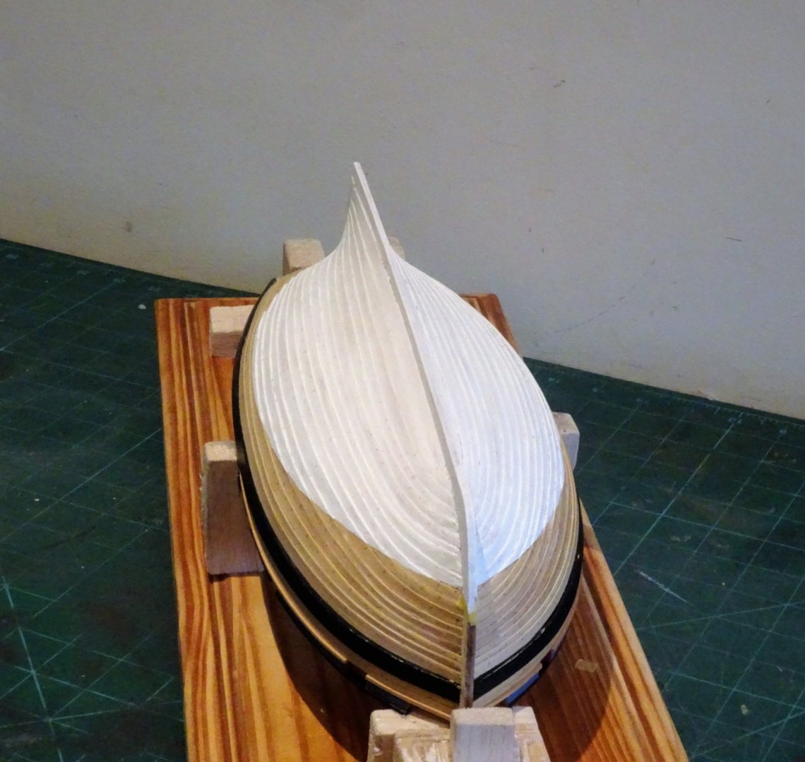
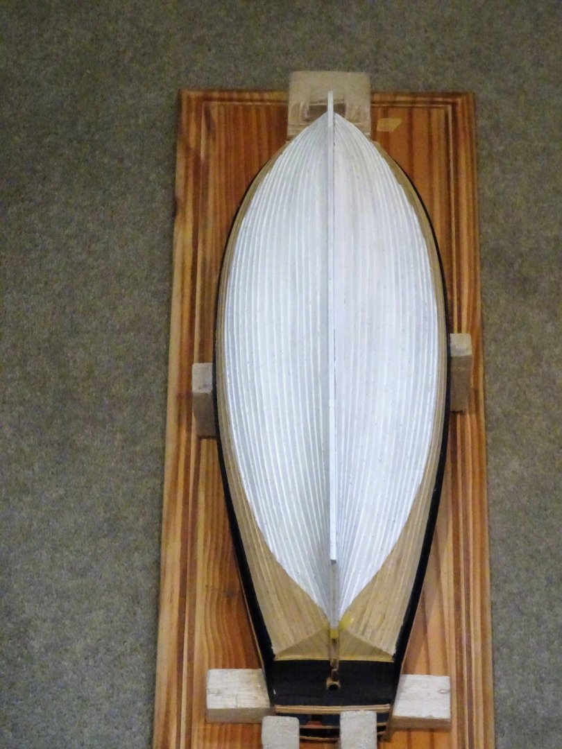
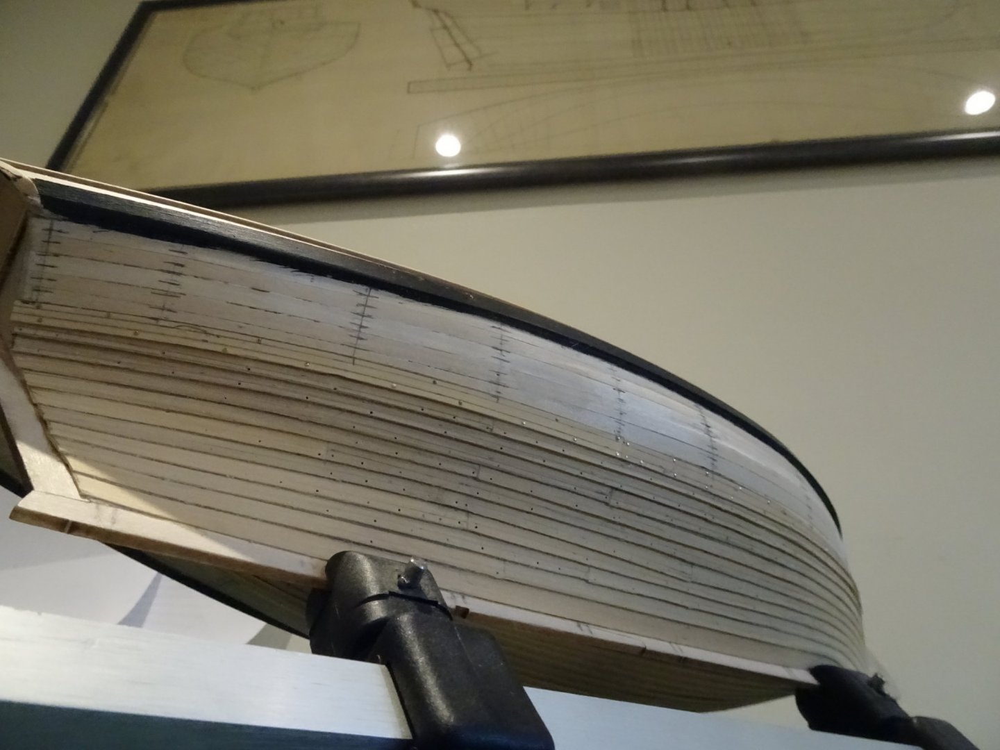
Post 19 The end of a long and spiling road After what seems to have been an interminable time at last all the lap strakes are in place. 2394 2393 The square tuck planking has also been completed. 2388 2381 With the last strakes in place the final shaping of the wale can take place. 2385 The wale at the bow is also fined down a little in thickness. This is not the end of the process, the planks have to be cleaned up and faired at the bows and stern, and approximately 2500 copper bolts have to be inserted to ‘secure’ the laps. I gave some thought about representing the roves as shown on the Alert book drawings but they would be incredibly small at 1:64 scale, and in any case the photo’s of the contemporary model of Hawke don’t appear to show such a feature, simply the bolts. The bolts will be represented by copper wire ca’d into pre-drilled holes cut close and tapped with a hammer to flatten the heads slightly. I now await a supply of copper wire to complete the task, but there is plenty of cleaning up work to do to keep me busy. B.E. 21/09/2019


- 335 replies
-
- 21
-
-
- alert
- vanguard models
- (and 1 more)
-
Thank you Nils and Mustafa. @Nils - still working out a strategy for the copper bolts and roves, but first I will need to clean up the planking strakes.🙂 @ Mustafa - The pins are very fine and easy to remove. I use a fine blade beneath the heads to ease the pins out a little and then remove with mini pliers. Cheers, B.E.
- 335 replies
-
- 3
-
-
- alert
- vanguard models
- (and 1 more)
-
Granado was a little too early for coppering as she was sold out of service in 1763. In the British Navy coppering of the fleet was underway in the 1770's and included not only larger ships but also cutters and sloops. The cutter Alert for instance was coppered in July 1777. B.E.
-
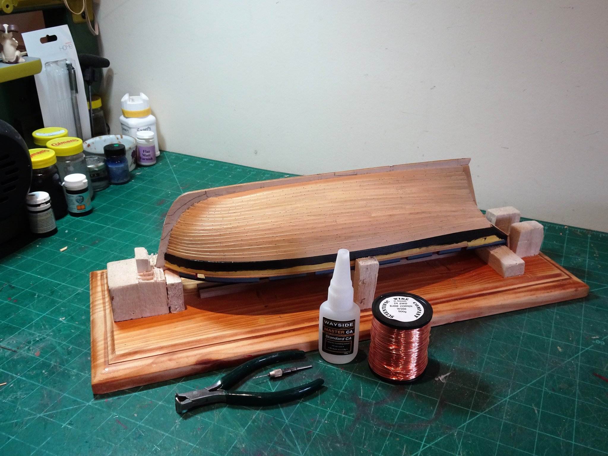
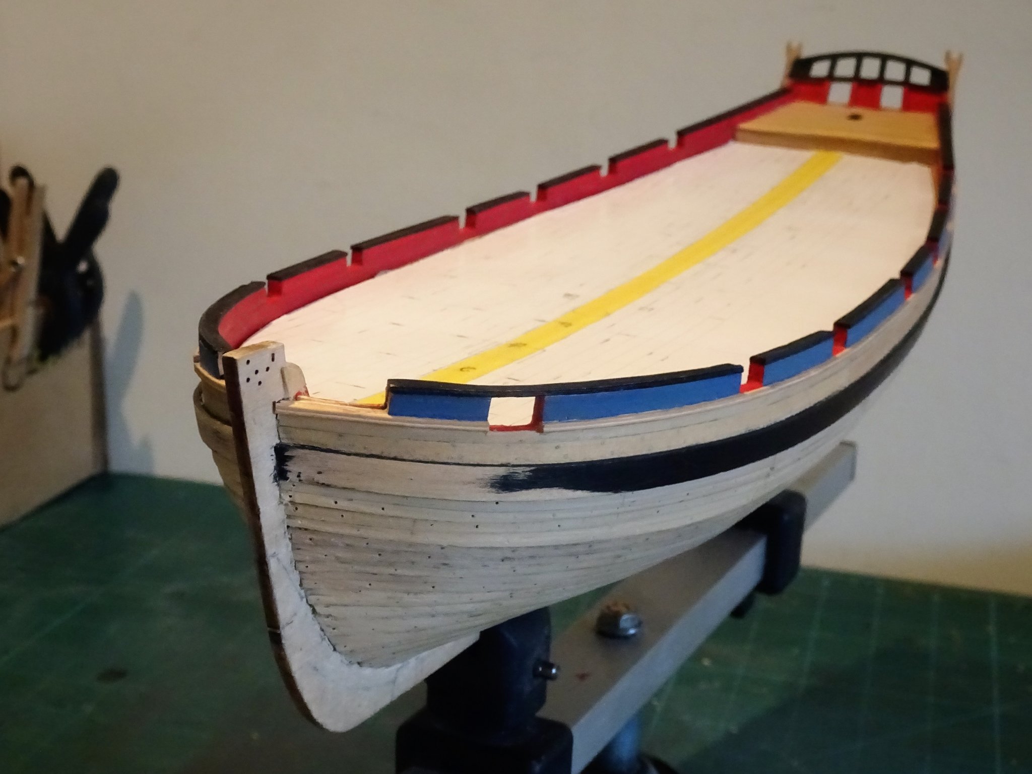
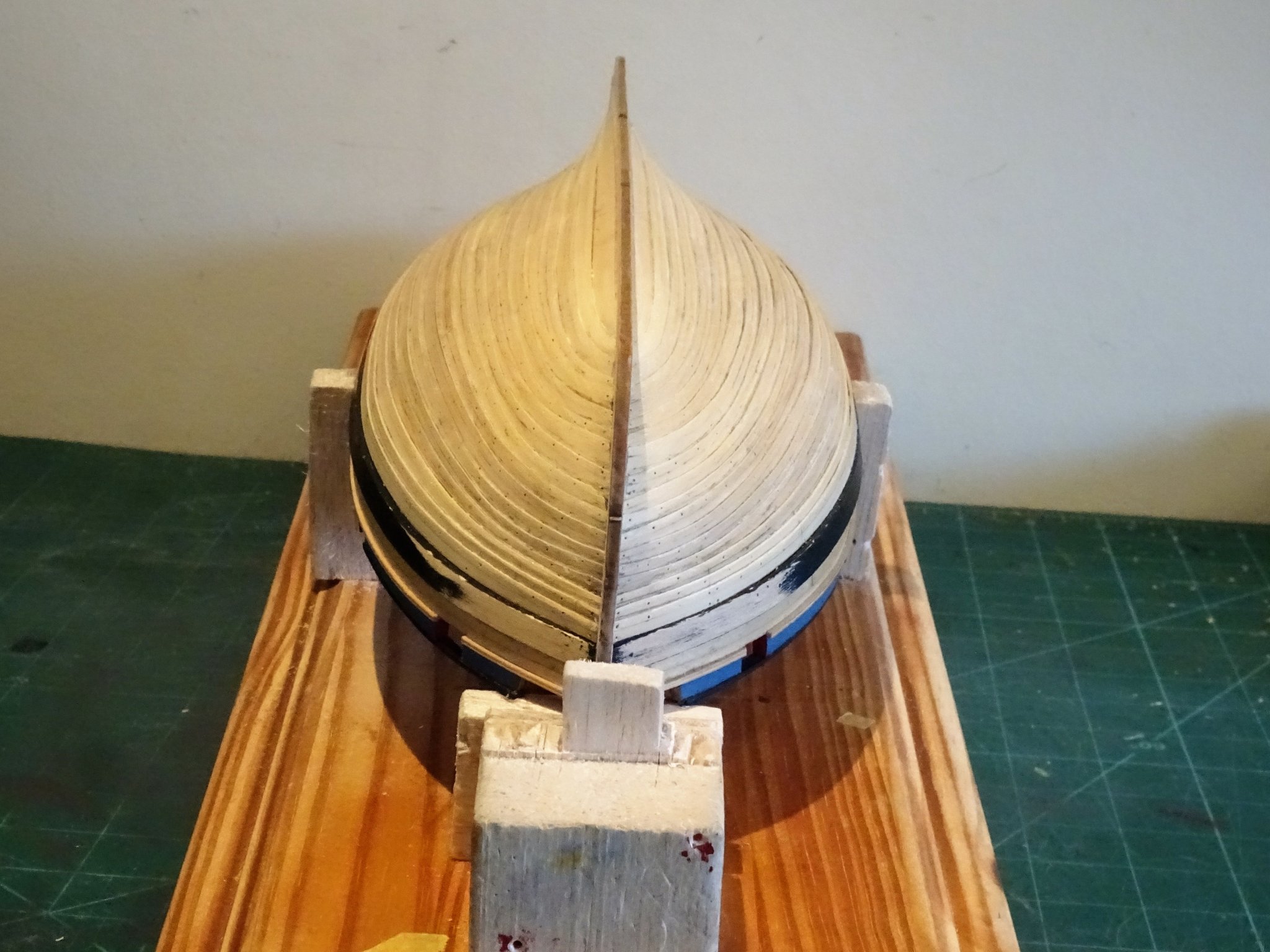
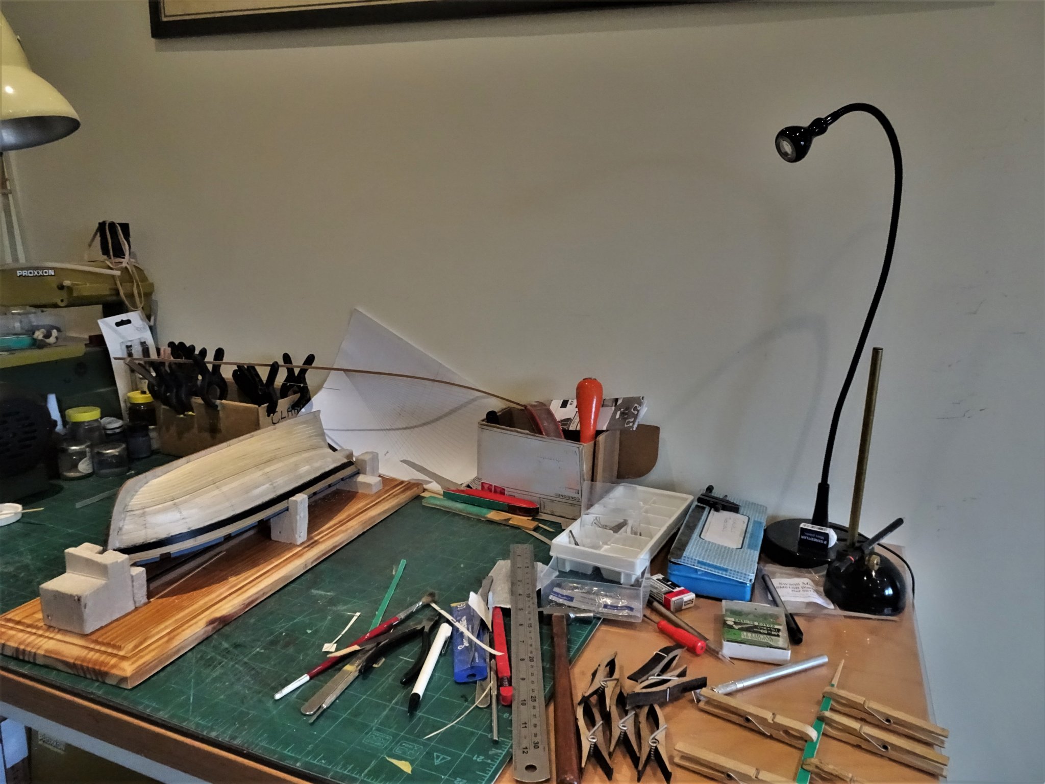
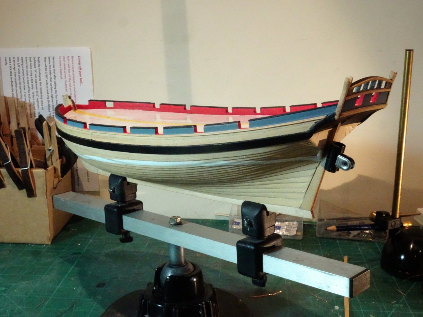
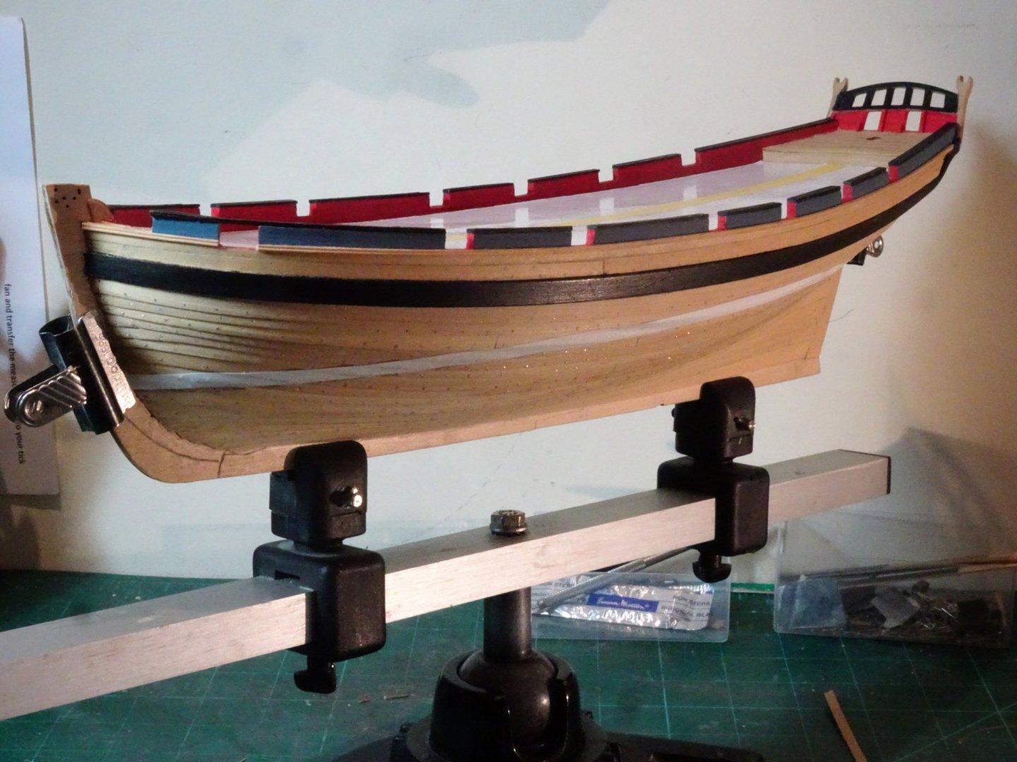
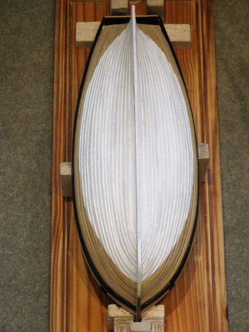
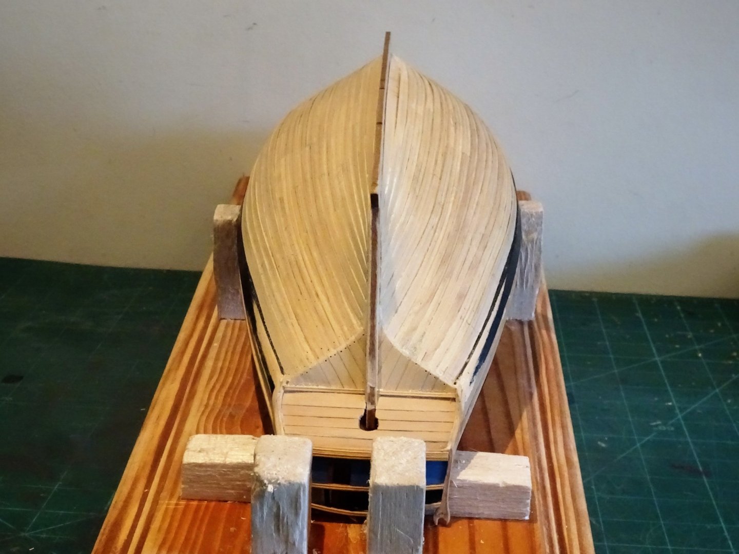
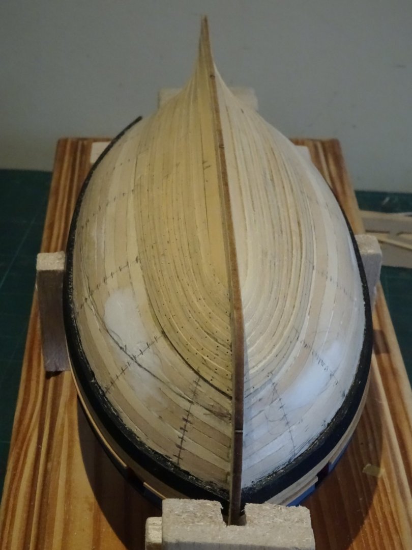
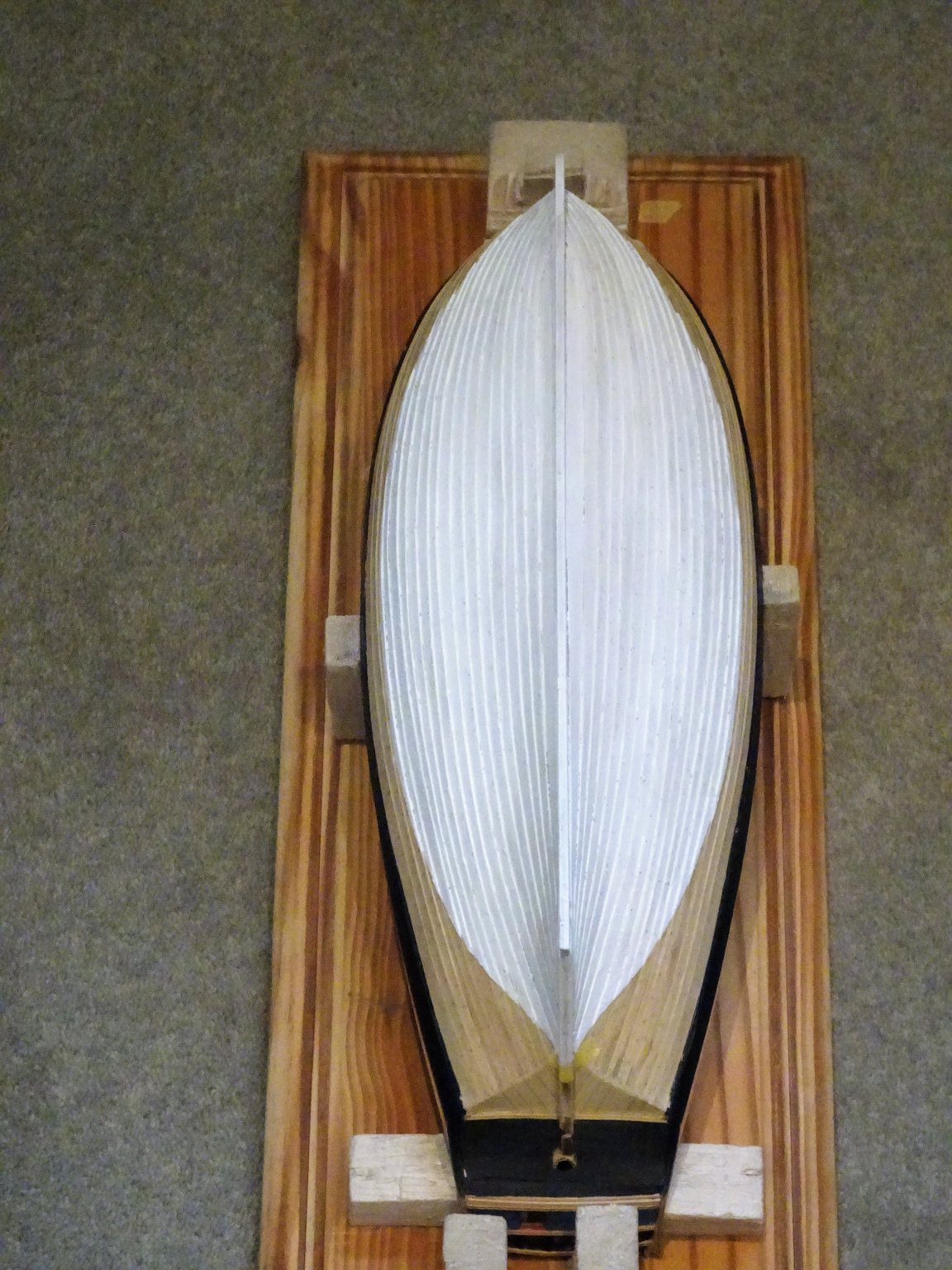
Post 18 Clinkering on. Time for an update, and review of progress. 2033 A fairly slow process this clinkering business, I am doing two strakes per day. 2035 Thus far each plank has been individually spiled, cut from boxwood sheet. I think this will be the case for all of them. 2038 Each plank end at the bow is thinned slightly and an individual rabbet cut in the stem to hold it. Very fine pins are used with the glue to hold the planks in place. I use Amati (Very fine brass pins (A4136/10)) These have a flat head just shy of 1mm ø with a 0.5mm shaft, perfect for the job. 2046 These are then removed. The pin holes aren’t a problem as the lower hull will be painted but will be re-drilled for representations of the bolts to be fitted. Before fitting, each plank is trimmed to the tick marks and is used as a template for the opposite side. 2045 At this stage I have completed 11 strakes and have started to fine down the lap of the strakes as they approach the stem and stern post. All still very much wip at this point but I’m now feeling more confident that it’s starting to look like a clinkered hull. B.E. 02/09/2019.


- 335 replies
-
- 22
-
-
- alert
- vanguard models
- (and 1 more)
.JPG.af8ee3910f7cad93ce3debd818e7f627.JPG)


.JPG.de73f7f4ce7fcca7b2ee2102bd038d2b.JPG)
.JPG.85e8474b32af90cc87732861b9e0a4c5.JPG)
.JPG.6bd310096685fa6749ebd93600875277.JPG)
.JPG.78574b4ba25a297df12b4ad941763125.JPG)

.JPG.3ec0b80dde84886ae4a807bb5b965fc1.JPG)
.JPG.274c9b39ad99454be514560fa814e752.JPG)


.JPG.c04524e7c7f0f34b2586f9d1e384601e.JPG)


.JPG.bf00c1f2bf3994fcbbf316c0dd28ee62.JPG)
.JPG.2fac051e9222029e20a1e6a83e86a4c4.JPG)
.JPG.a154498f53734da250efced74fdc6510.JPG)
.JPG.1df61149aefb50893416a34fd8a67a64.JPG)

.JPG.47fb9b749f95af680b331281547fa7e0.JPG)
.JPG.051e90d7ce0f410fda819094d2b0d5ad.JPG)
.JPG.9a70af15bcc4cdc1364a1db71db0719f.JPG)


.JPG.280a2dab800cc429885552c2899a4459.JPG)
.JPG.a486a77c689813d5ba0c6f1c76bb3987.JPG)
.JPG.2d8f24ce68fd311d5f899cdd35ce4518.JPG)

.JPG.fde55e863af6ebdc43385ef4baa191e0.JPG)
.JPG.ae77c331a3e28328cb2313f17796b444.JPG)
.JPG.78f9722a1c68fe91232f4bca0520aaef.JPG)
.JPG.9edbbe5f03186e89a5d6a30b6c7fd057.JPG)


.JPG.e2bf7299c9bd8aa42d0e93c5f3b20f55.JPG)
.JPG.24f2ef9cef2c807bf44deae81b2361d4.JPG)

.JPG.2ea12d3d248963604c250e64b2aed4e6.JPG)
.JPG.6464f48078a678497edf915e31ee542a.JPG)
.JPG.927e7502223b5f39ad39bd91fb460522.JPG)
.JPG.45c6d765d12c12fd768ae3808417cbb3.JPG)
.JPG.06e58d60a21c7edb7063110e931efbf2.JPG)
.JPG.c3aabe81c4b4c0d63b9e1fdd93b301a2.JPG)


.JPG.b00370421bf008210735fc49b5f59ab4.JPG)
.JPG.16d10ae305dd51e15d46097077674b73.JPG)