

Jack12477
-
Posts
5,674 -
Joined
-
Last visited
Content Type
Profiles
Forums
Gallery
Events
Everything posted by Jack12477
-
 Hi OC ! I'm here, even beat the 3 Amigos getting here from the trifecta build ! Looking good !
- 229 replies
-
- 6
-

-
- trafalger class
- airfix
- (and 2 more)
-
Eric, your approach is pretty much the same approach I took building my version of the kit, especially since my work table was only 2 ft by 4 ft in size.
-
Stage Coach by Sjors - Artesania Latina - WOOD
Jack12477 replied to Sjors's topic in Completed non-ship models
Wow ! Nicely done, Sjors. -
DN Iceboat by MikeR - FINISHED
Jack12477 replied to MikeR's topic in - Build logs for subjects built 1901 - Present Day
Wow ! Very nice Mike. I can just see it gliding across the ice. You did a great job capturing all the detail. Are you going to include a sail ? -
DN Iceboat by MikeR - FINISHED
Jack12477 replied to MikeR's topic in - Build logs for subjects built 1901 - Present Day
Mike, great job on the runner skate. Even the "parking" brake looks great. -
Nice, Greg! Great job on the rust and grunge weathering. Looks great alongside your other warships. Okay, Carl, your turn !
- 1,090 replies
-
- 10
-
-
- showcase models
- vendetta
- (and 2 more)
-
I have to agree with CDW, capsicum is red peppers native to the Americas, see https://en.m.wikipedia.org/wiki/Capsicum. It's related to nightshade which we consider to be a poison.
- 1,090 replies
-
- 7
-
-
- showcase models
- vendetta
- (and 2 more)
-
Gee, if you guys are worried about Denis being so far behind, you two could stop and treat your audience to some fine food. Carl could whip up some of his world renowned Dutch sherbert/sorbet and Greg could fire up the Barbie and rustle up some of those fine grilled Australian prawns. Maybe Denis could then catch up to you. Hmmmmmmm!
- 1,090 replies
-
- 8
-
-
- showcase models
- vendetta
- (and 2 more)
-
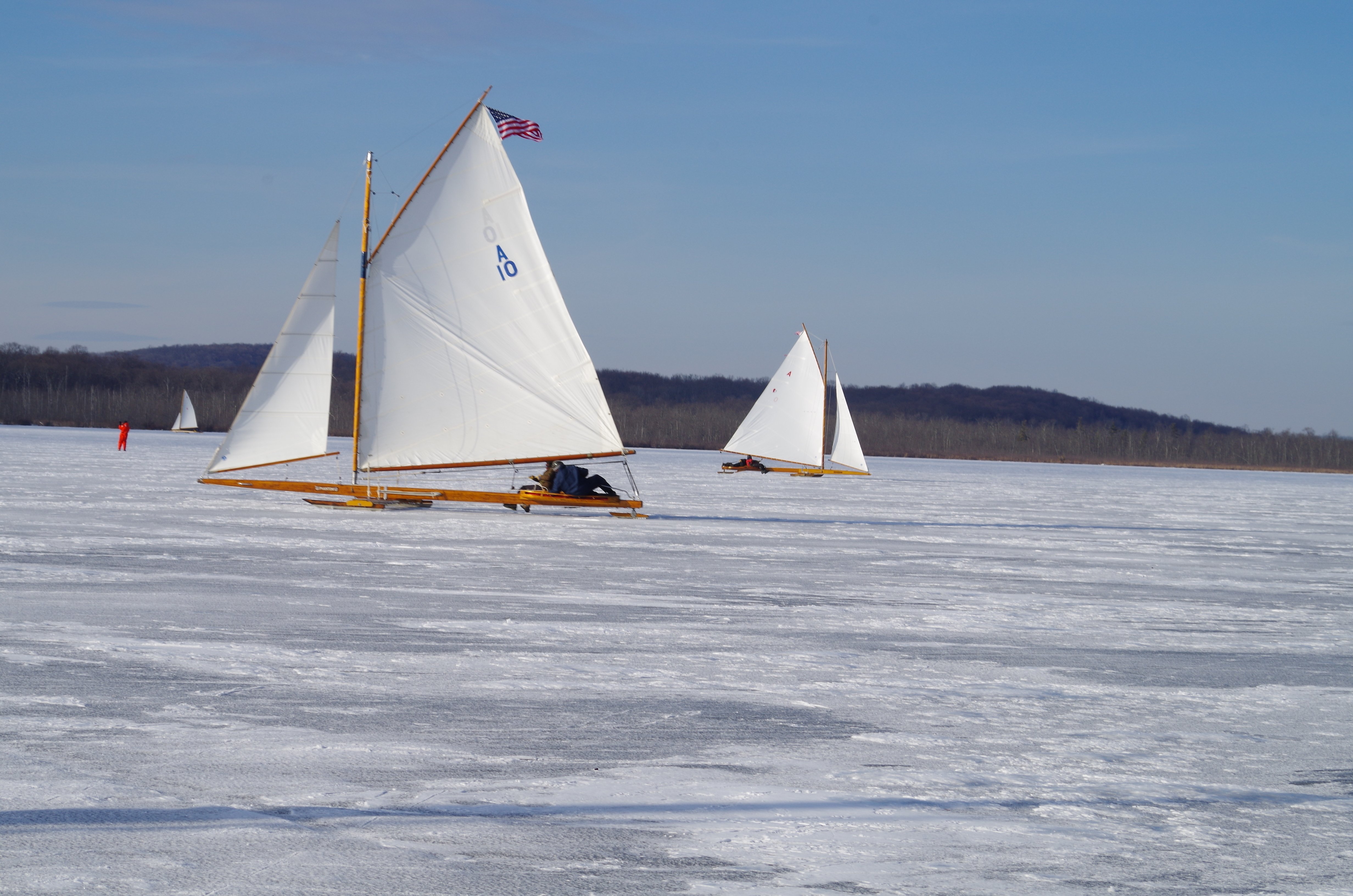
Thanks Tom. Yes some real serious speed. Back in the early 1990s a couple of our club members took our Class 1 50 ft ice yacht Jack Frost up to Lake Winnipesaukee for some serious sailing. They clocked it, using their GPS, at 91 MPH on a 16 mile long run down the lake. This is a 2,000 lb boat.
-
I usually substitute Chuck's (SYREN) wood cleats for the metal ones, he has 3 or 4 sizes.They look much better. Check his site.
-
In the meantime things may get side tracked with family - I got a call the day after Memorial Day (US Holiday) that my younger brother's cancer treatment has stopped working and he's gone into at-home Hospice Care. He's been fighting it for the past 5 years. This cancer has no cure. Drove up to western NY yesterday (550 miles round trip in same day) to spend some time with him and his wife. So I may disappear for a while as I will probably be making quite a few more trips up to see him.
-
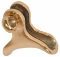
Been trying to fabricate the saddle for the gaff bridle, but haven't been able to make one that looks real on not way over scale. The look like the following pictures. Tried using some 1/16 hollow brass tubing filed down on one side to make a U shaped saddle but does look right to me. So I will keep experimenting.

-
WOW ! I'm with the others Piet, you really nailed it! Great looking model/diorama. Even my wife loves it.
- 378 replies
-
- 11
-
-
- java
- pacific crossroads
- (and 2 more)
-
Let's see ! We have popcorn and peanuts ! Did anyone bring Cracker Jacks too ! <pun intended>
- 1,090 replies
-
- 8
-
-
- showcase models
- vendetta
- (and 2 more)
-
I have a very large bag of roasted peanuts in the shells. You know ! The kind we used to get at the Ball Park. I could always rain the shells down on him after all we rafter sitters are in the peanut gallery, right !?!?
- 1,090 replies
-
- 6
-
-
- showcase models
- vendetta
- (and 2 more)
-
Miter boxes----What is the best one.
Jack12477 replied to roach101761's topic in Modeling tools and Workshop Equipment
Welfalck, the one that uses razor blades with saw teeth is quite rigid thanks to a rigid spine and works well on small stuff. And it is very easy to set for repetitive stuff too. The others I too have trouble with accuracy. -
Given the scale of the boat that certainly looks like a Garrison Flag, Dave. Nice touch.
- 742 replies
-
- 8
-
-
- constitution
- frigate
- (and 1 more)
-
Miter boxes----What is the best one.
Jack12477 replied to roach101761's topic in Modeling tools and Workshop Equipment
I use a combination of these three (available from MicroMark) a: micro miter box (use with micro razor blade saw pictured) b: duplicating jig c: aluminum miter box with saw Never had a problem with the aluminum box dulling the saw blades. I did use a plastic one for a while until I sawed right thru it after repeated use. -
I wish this thread had been available when I was struggling to build the roller for my Willie Bennett model. Likewise your explanation of the construction of the davits for the pusher boat. Nice work, Frank, and great explanation of the process. Your level of detail is perfect.
-
DN Iceboat by MikeR - FINISHED
Jack12477 replied to MikeR's topic in - Build logs for subjects built 1901 - Present Day
Ah yes, the curse of all ice boaters. Model looks good, like the choice of woods. -
DN Iceboat by MikeR - FINISHED
Jack12477 replied to MikeR's topic in - Build logs for subjects built 1901 - Present Day
Mike, do you stil have/sail your original DN ? Tom, the more the merrier