HOLIDAY DONATION DRIVE - SUPPORT MSW - DO YOUR PART TO KEEP THIS GREAT FORUM GOING! (Only 13 donations so far - C'mon guys!)
×


DaveRow
-
Posts
691 -
Joined
-
Last visited
Content Type
Profiles
Forums
Gallery
Events
Everything posted by DaveRow
-
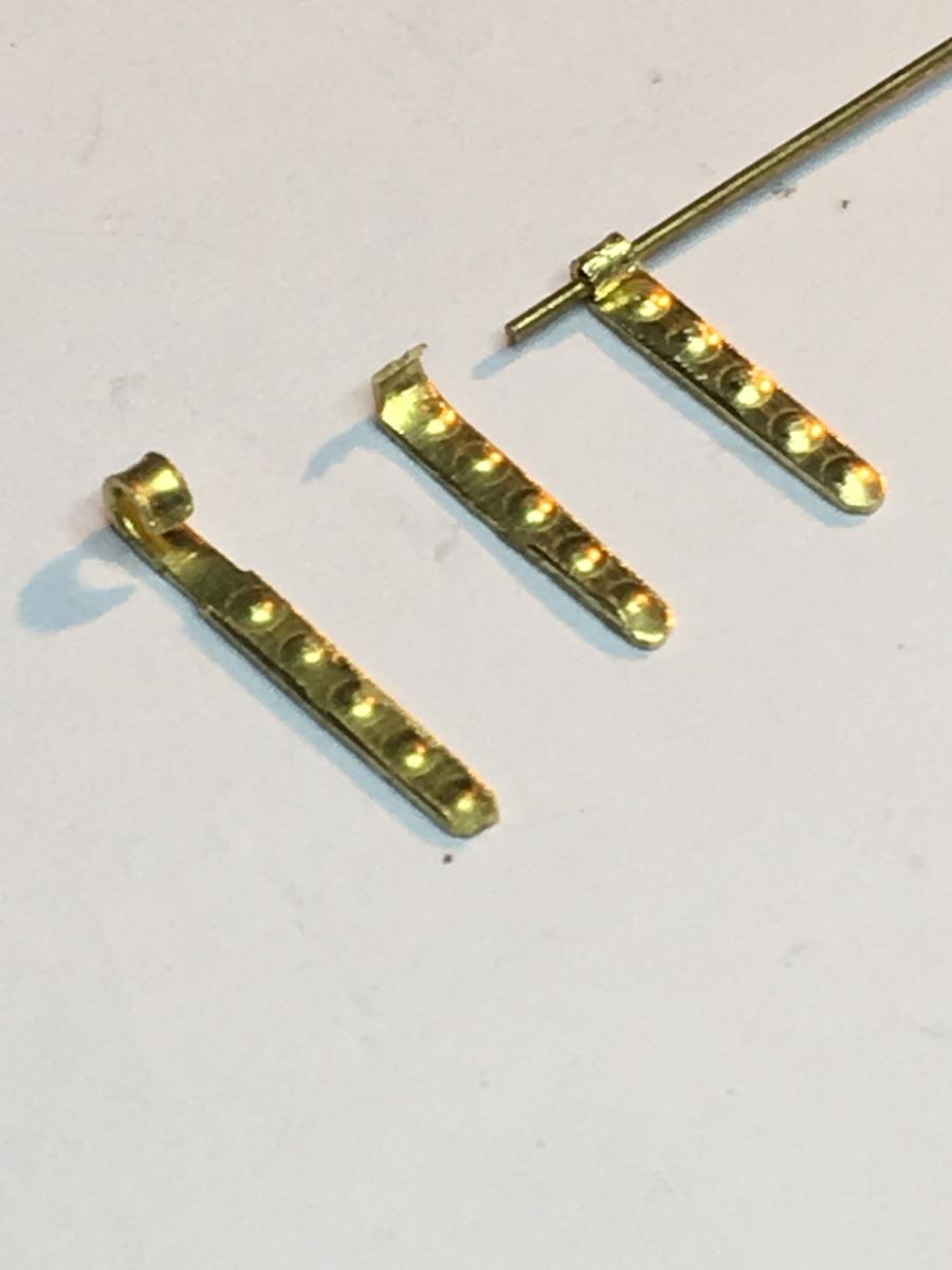
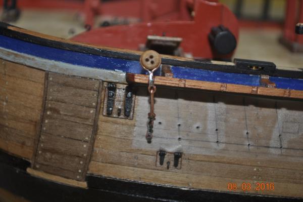
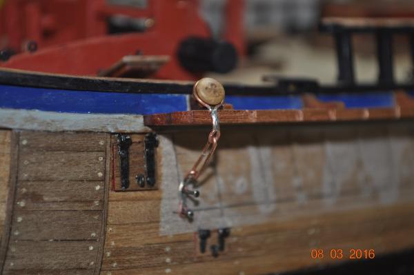
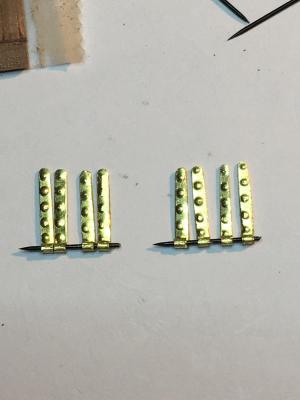
 Chains and links to the channels I mocked up my first(prototype) of the port fore channel chains. I am actually very pleased the way this one has come out. Only another 31 to make like this set for the cats_eyes, + 20 shorter cats, all for the hull channels, another 6 for the back stays, then all the rigging ones. I'll have to work out a mass production line for them ! I used a resistance welding unit I bought from the USA, an American Beauty SC250, to join(weld) the copper wire(many thanks to Pat, Banyan for providing advice on this unit). After a couple of practice runs on wire loops and joints, I got the hang of using the probes. temperature, flux and solder. Very happy so far how fast and neat it joins the wire. Dave R
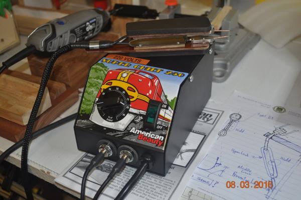
-
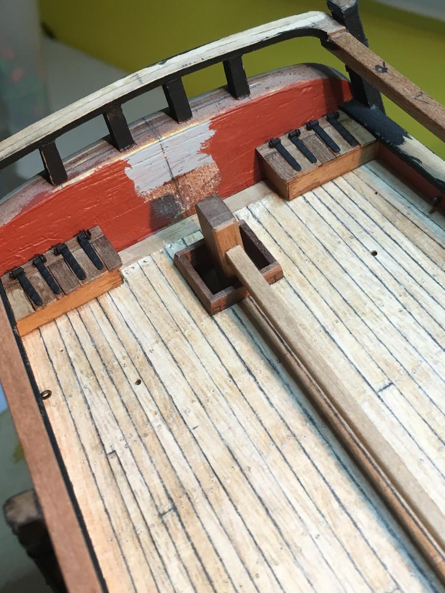
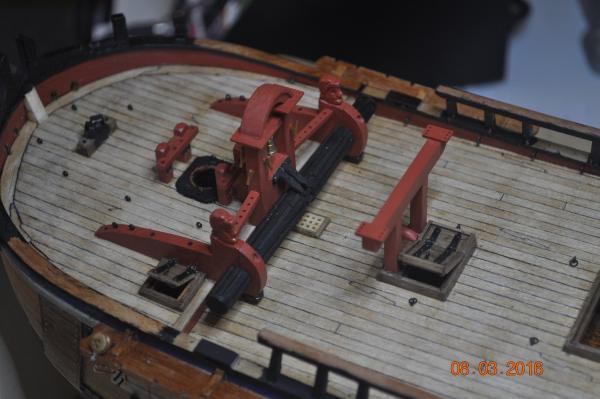
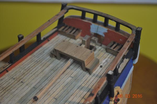
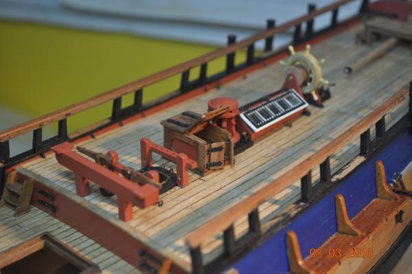
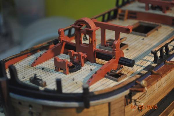
Update in the Shipyard. The time come to fix in place the deck furniture items I have been constructing for the last few months. Here are a few pictures of the items. Fore Mast Area: Mid Ships: Stern: I keep finding eye bolts(for the standing and running rigging) to add onto the deck, best to add in now whilst not so cluttered. I believe I am up to something like 40 now. Still a few other items I have made to go on, wait further in on the build to fix after the middle pulleys and ropes added. Dave R
-
Good work Chris, I agree, you think the planking takes a while, well lots of fun ahead mate. Are you going to treenail the hull ? Dave R
-
Hi Greg, Not sure about the discipline, I kind of wanted to stick with timber belaying pins, I just need to get my head into gear and just do them. If I need more than 30, well another stint. Slow going, but coming along. Dave R
-
Hi Slog, It is an after market housing I got from Rob Mallett of (MTW); mytoolstore.com.au He is in Brisbane, operates from under his home, specializes in small hand tools and accessories. Some time ago I fiddled making a home made Lathe and in talking to Rob, he had previously sourced the Dremel housing. PM if you want to call him for the No. or it is on his Web Site. Picture of an earlier version of the home made Lathe, with housing. I since have bought and set up a Record Power DML305 for spar production. Dave R
-
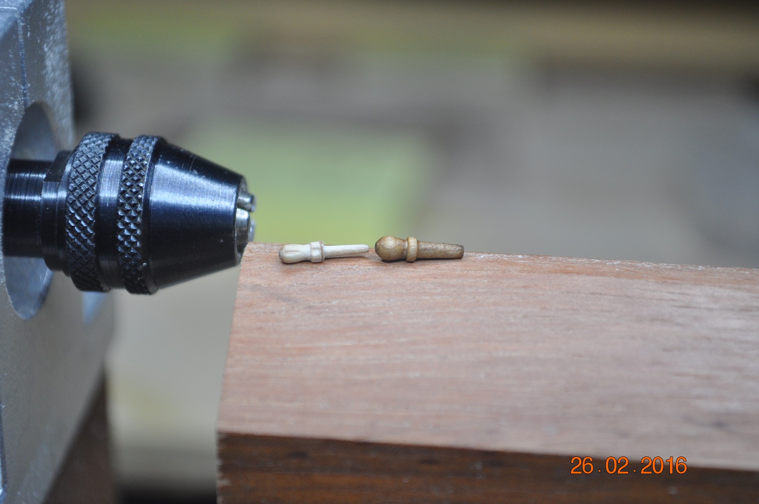
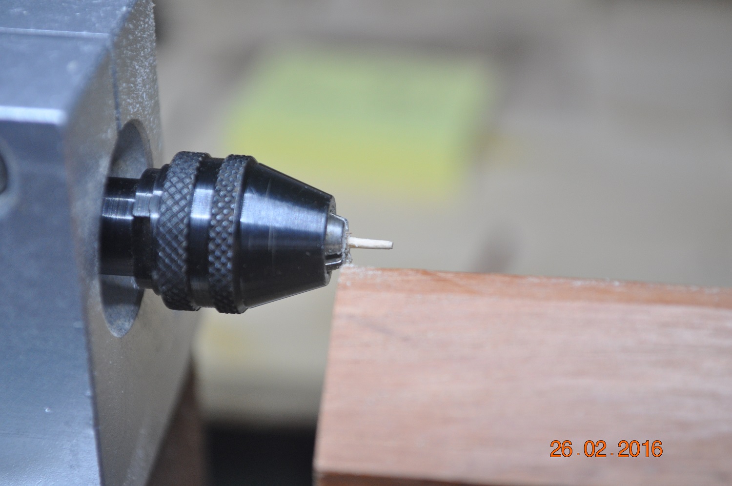
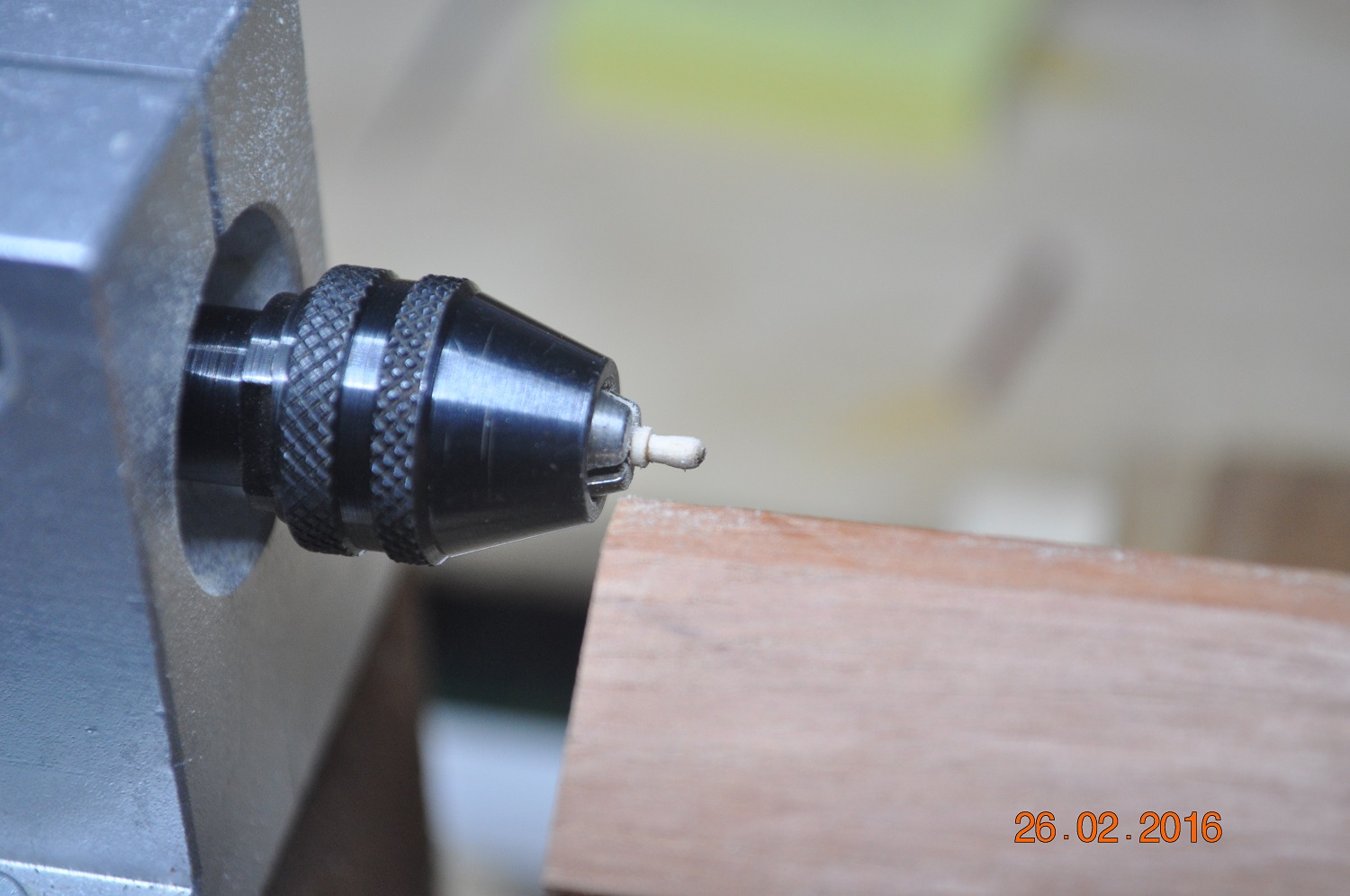
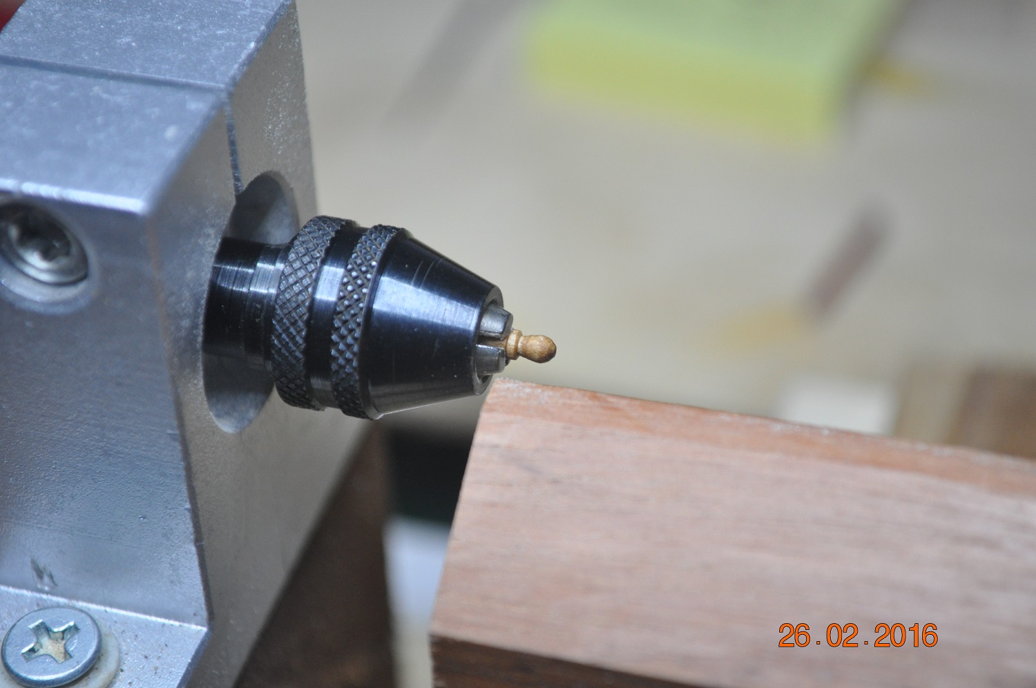
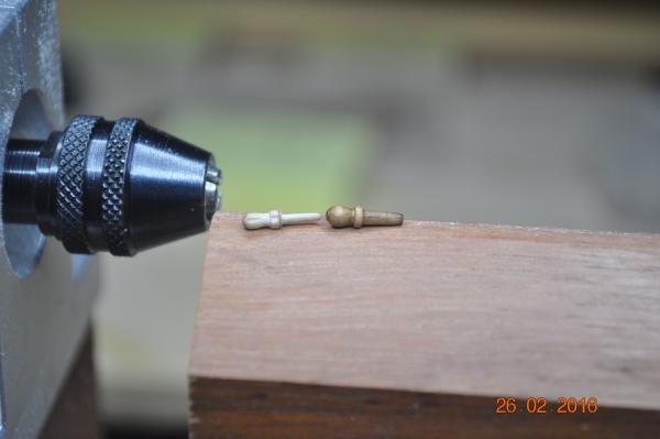
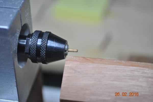
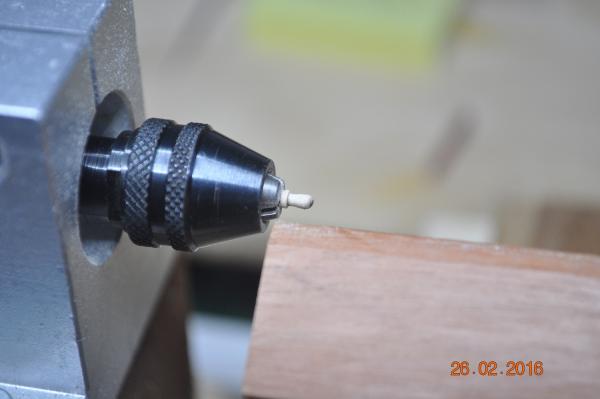
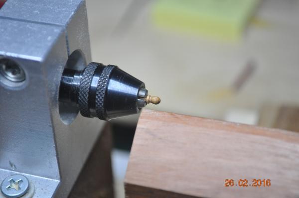
Belaying Pins We touched on this topic some while ago. The smallest timber pins I could find and purchased were still too thick on the shaft end. So I put them through the end of my Dremel chuck and shaved each down. Took a while and with much care produced a batch of smaller belaying pins. The process that finaling worked well: 1. slide the shaft end in first and 2. turn the head down a wee bit 3. reverse the pin with chuck holding the shaft. 4. shaft the shaft down. 5, new and old sized pins. I remodeled about 30 of the buggers. Dave R

-
Hi Paul, Each channel slides(resides) into a slot and together with the knees, when I finally epoxy the lot, they won't be going anywhere. See 1st Pic log #305. The dead eyes/chains to the hull ? I have seen from quiet a few logs, this is where(from the side stay pressures) the lower plates/restraints pull out. I have pre-drilled under-size holes for the pins I use - so each is a tight fit. The plan is also to CA the fitting to the hull side. One could also glue the dead-eye chain to the channel so it takes some % of loads ? Not too keen on that idea. Plenty to think about here ! Dave R
-
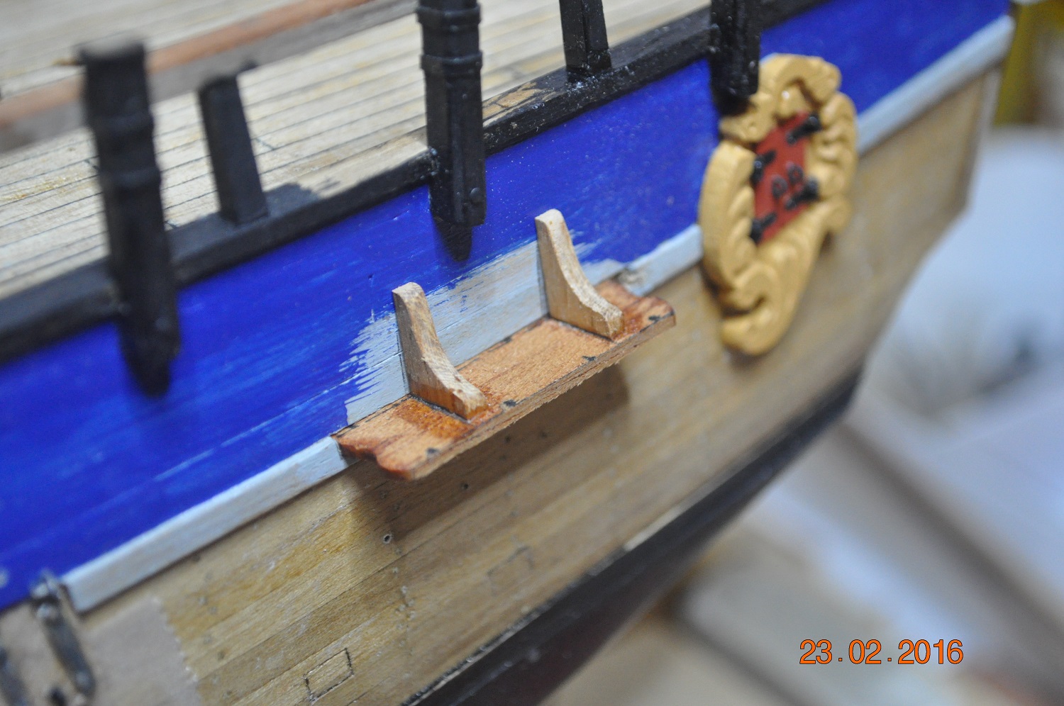
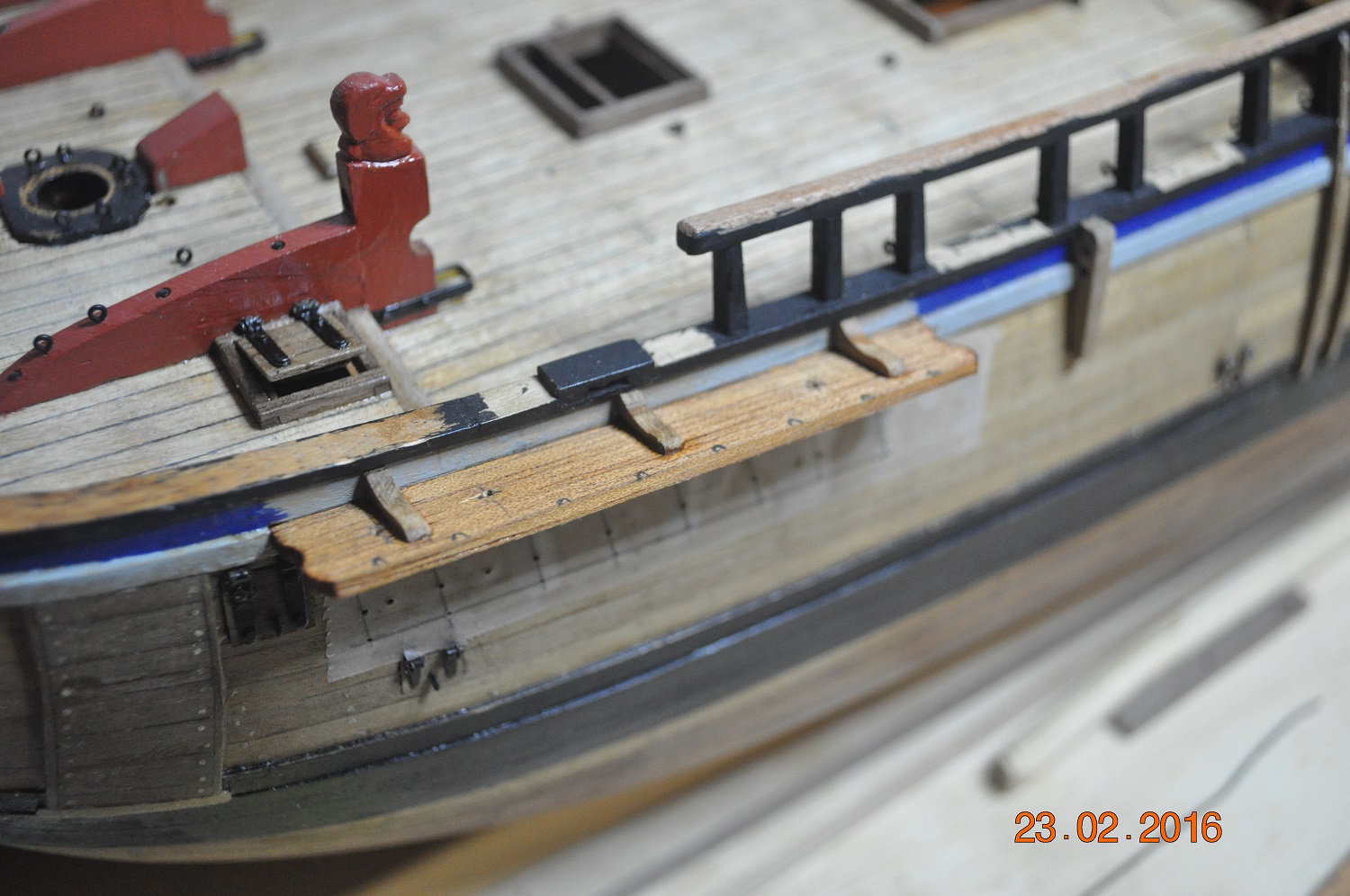
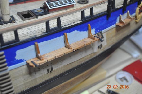
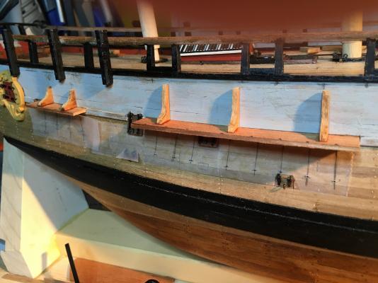
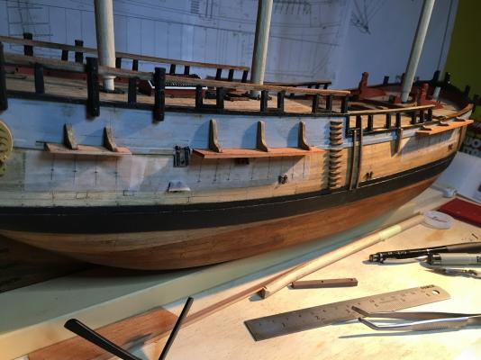
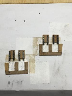
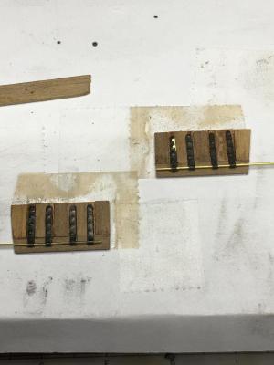
Channel Update, Work continues shaping and fitting the channels to the hull. Positioning the running rigging eye holes for the mast tackle. Studding Sail boom brackets. Recess for the dead eye chain Fore Channel Mizzen Channel Dave R


-
Steve, OMG, I have this to look forward too !! Great effort, looking really good. I'll certainly have to come back to your log when I start the rigging. Dave R
-
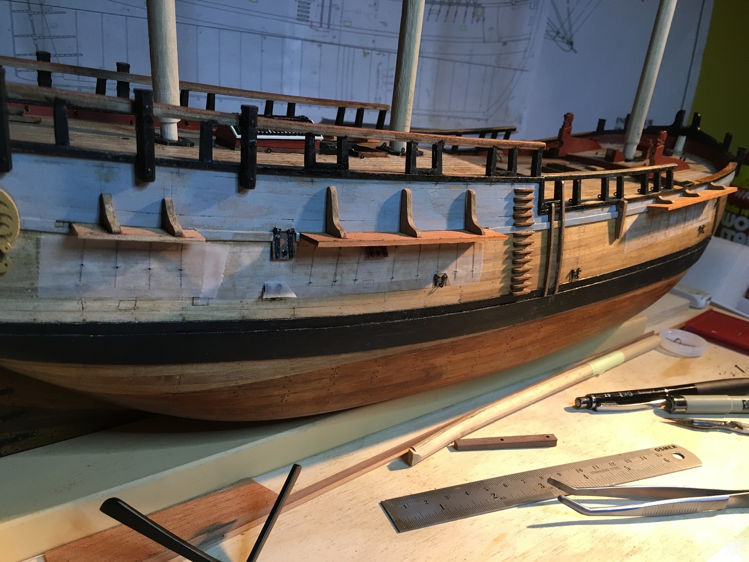
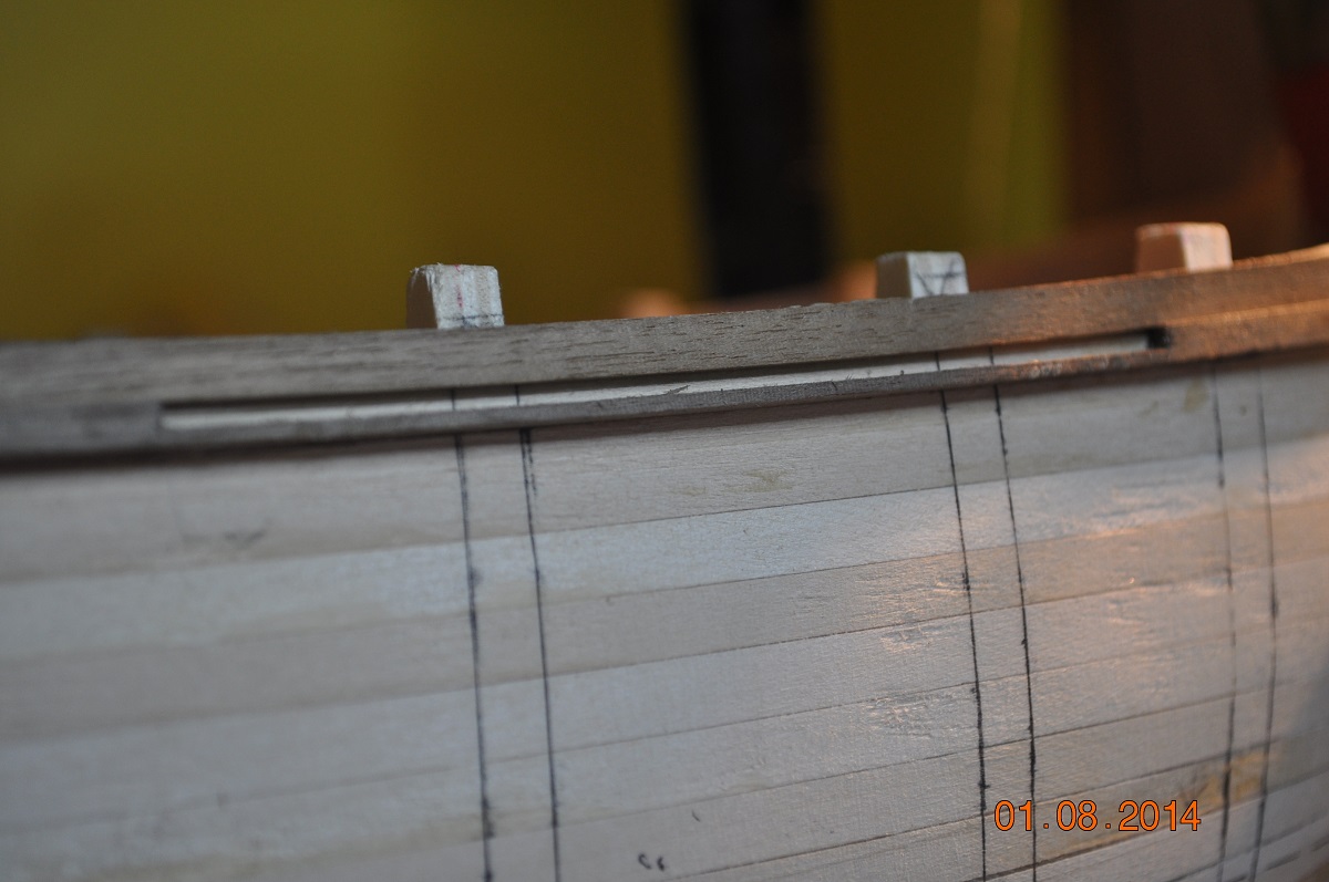
Shipyard is back in action. Started fitting the channels on the starboard side of the hull. Back in Aug 2014: I cut slots in the side rails for the channels to fit into. I had to slide the mizzen channel forward towards the bow 4mm so the stays missed the cannon post. Test fit, not fully glued in yet. Just the knees glued to the channels. Some more work on them(holes for fittings) to go before fully gluing into their slot. When fully glued in place should be nice and strong. Also whilst fitting, I placed some clear tape on the hull to draw through/down the stay lines to locate the chain plate(angles) - drill bottom holes. Dave R

-
Nice work on the hull Dashi I'll look forward to see your shipyard progresses the build. Dave R
-
Hi Pat, The swivel guns are taking a nice shape. You could add/slide a timber handle onto those shafts ? My AB resistance kit arrived today. Cannot wait to get into some test welding, before parts for the boat. Dave R
- 517 replies
-
- 2
-

-
- Endeavour
- Artesania Latina
- (and 1 more)
-
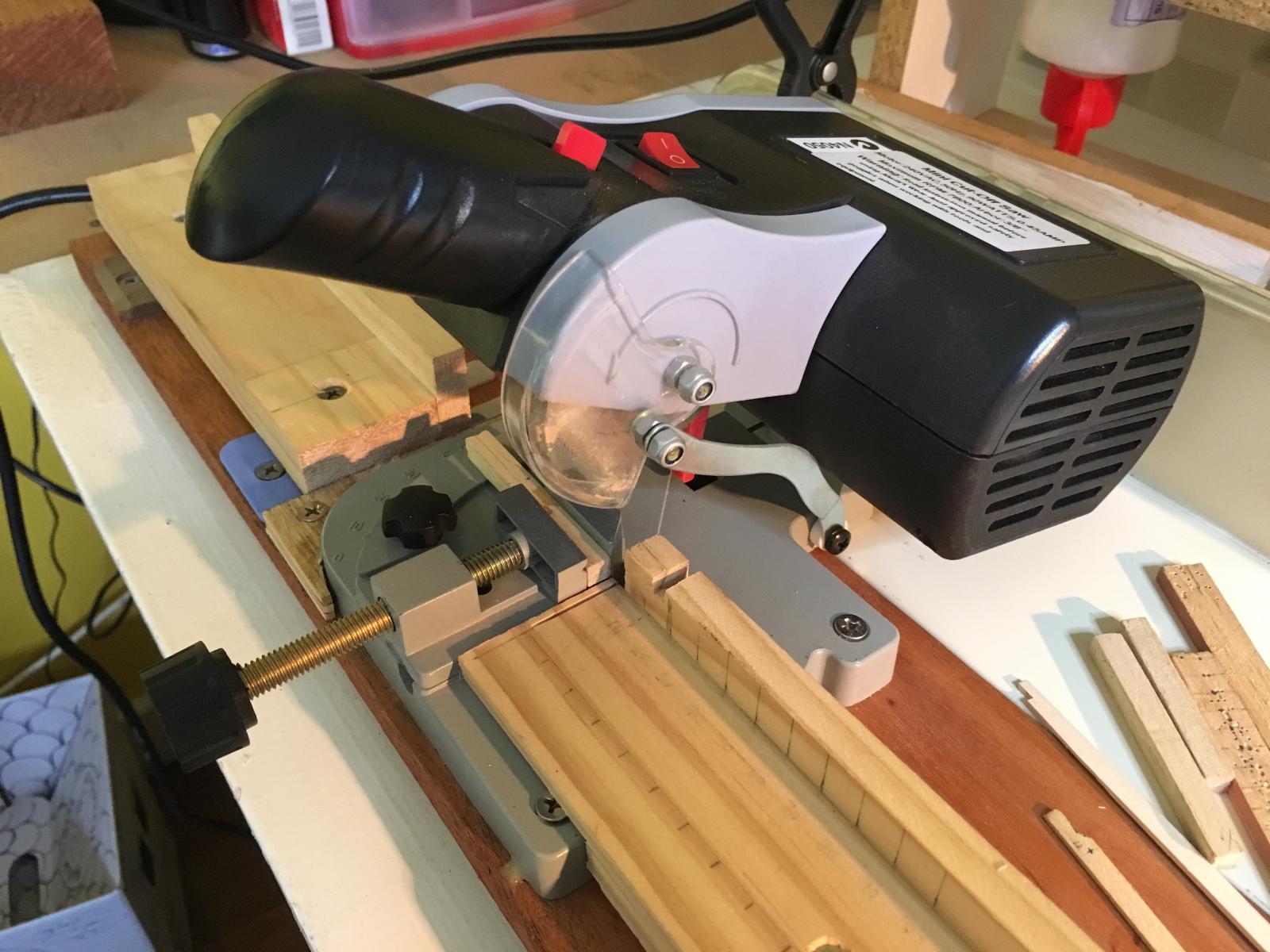
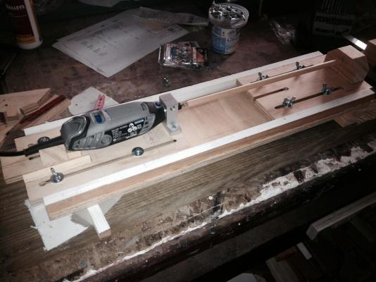
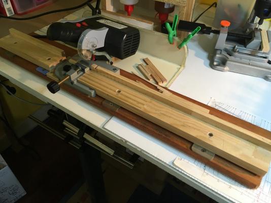
Hi All, On equipment. I bought this little mini drop saw some approx. 12 months ago. I wish I had this little item from the outset of the construction. I did all the planking on the hull, cutting planks by hand. I've added run in and run-out table/s. I can clamp timbers to the back of the tables to hold or for a stop. Recently, I added a metal flashing at the rear to catch dust and off-cuts, I use it so much. If you buy anything, I can recommend this is a must, as it cuts really neat square joints, 45deg to 90deg. I reckon I am up for replacement blade, I have used it so much. Dave R

-
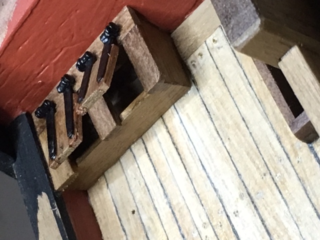
Cabbie, These ones are only glued. very small to put a pin in, and I don't intend to open shut them. At times the glue/joint fails if pressure applied or glue not fully in contact between metal and timber. Usually I glue and also pin(for strength) them into the hatch/lid timbers. Dave R
-
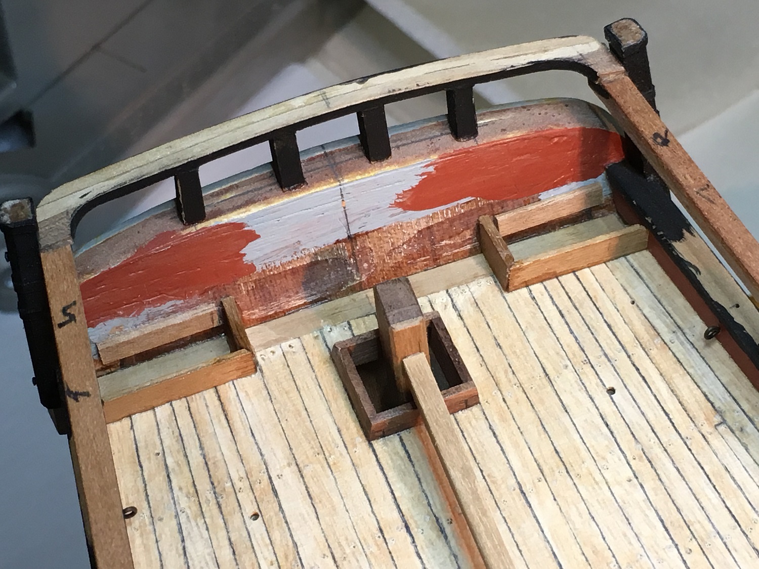
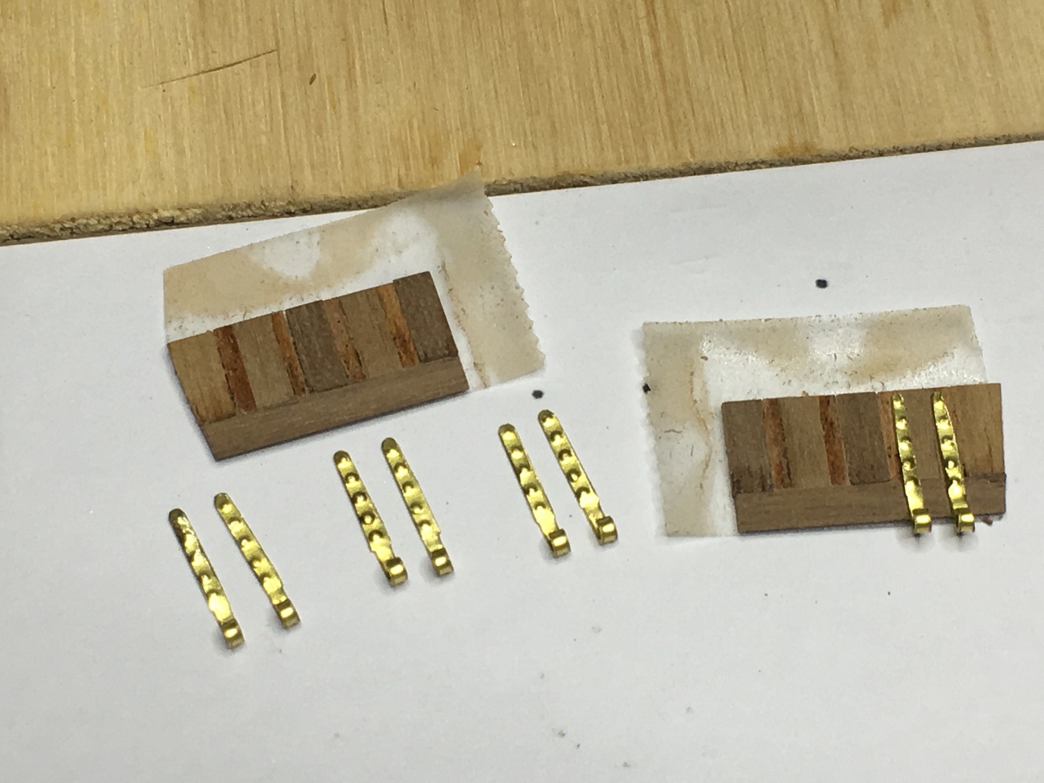
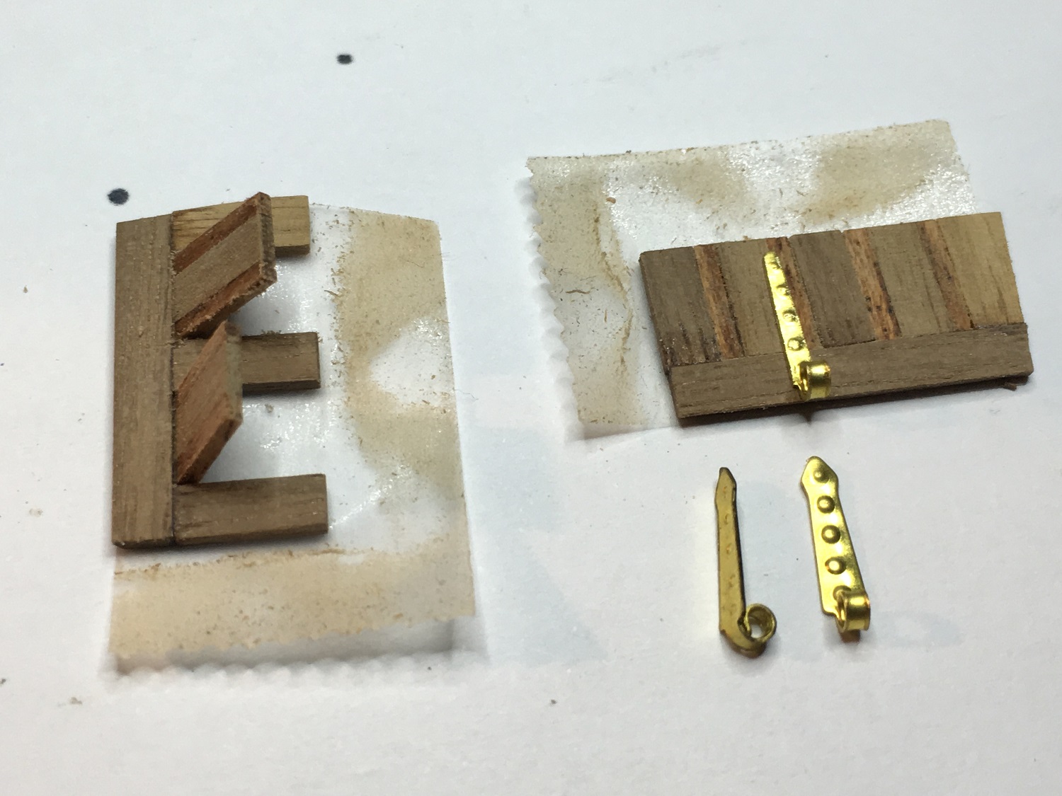
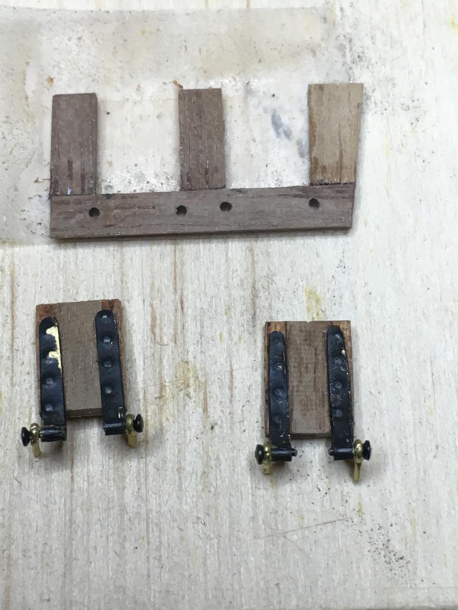
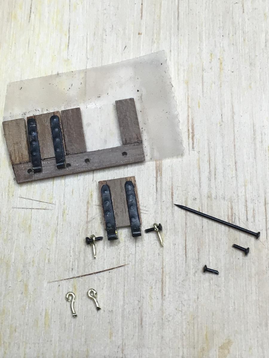
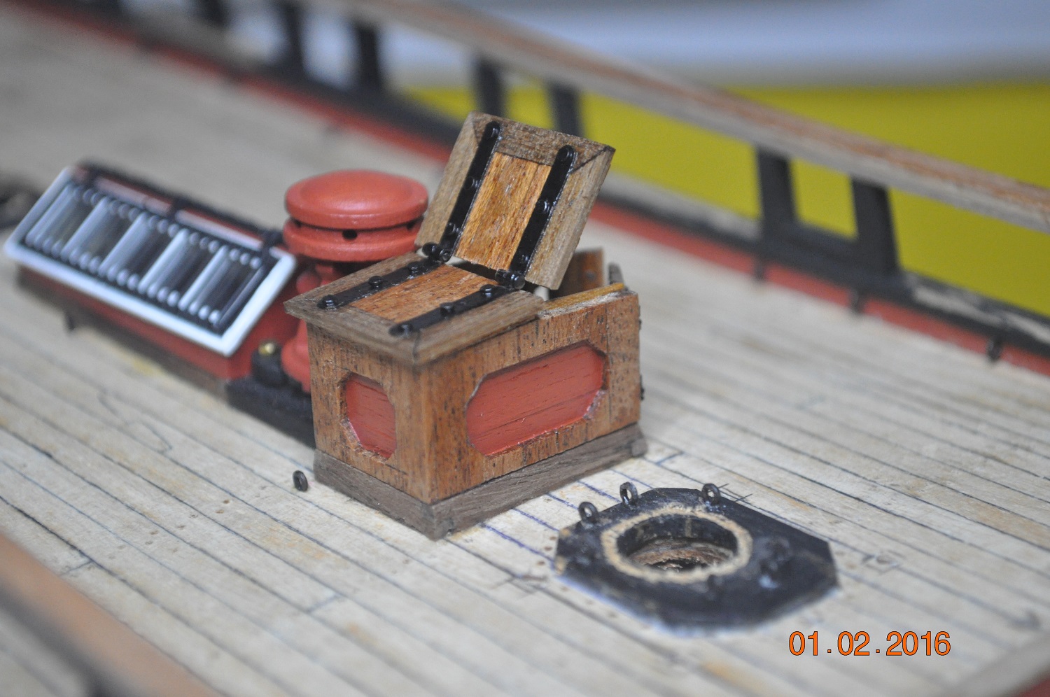
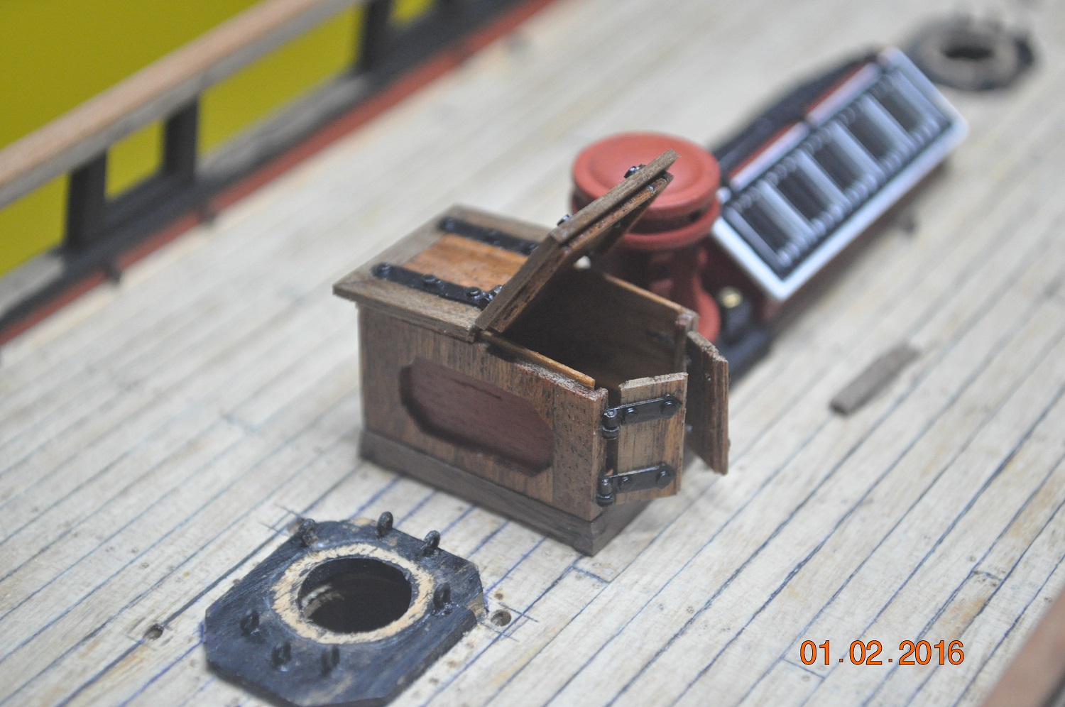
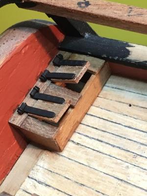
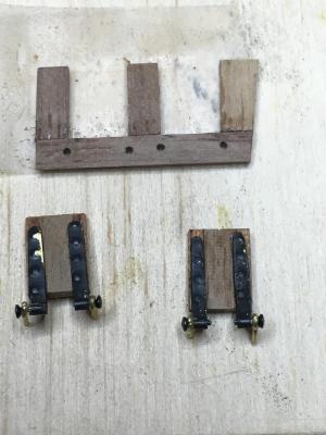
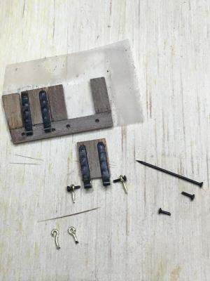
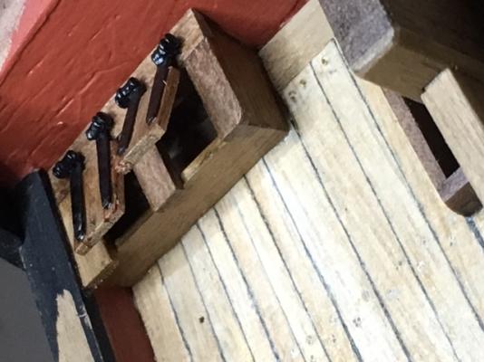
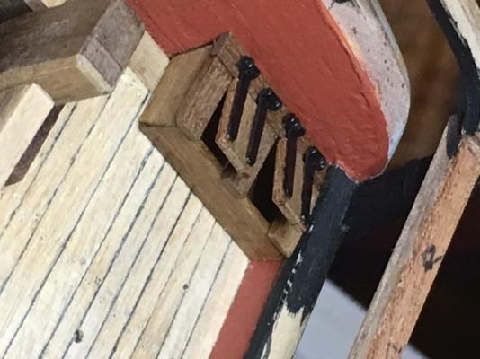
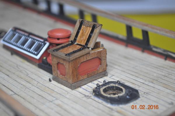
An update to work on the stern Flag Boxes(I believe they are called) Probably used for storing flags and assorted attachments. I thought I'd run a bit of a log on the process I use to make the hinges through to end. I don;t know how some of you modelers make things so small. This is how I do it. Lets start with the plan on the rear deck, the starboard flag box highlighted(from the AOTS): Create and fix in place port and starboard box frames for the lids to fix to: The lids; I made the lid/frame from left over 1mm planks: Selected a purchased hinge to bash into a smaller version for this application. Hinges bashed - grind and filed thinner. The end of each curved to allow a thin bar(actually a model railway pin - so very thin) to pass through as a hinge pinion(is that the correct word?). Blackened and CA/glued to hatches. Make some very small pins(from the railway pin heads) Craft some eyelets(fairly rough but you do not see them in the end really) Loose fix the pins & eyelets to the hatches: After touching up the black, gluing in place, ended up like.... A couple of coats of clear, should bring the timber grain out and onto the flag pole fixtures. Updated - coat of clear. Dave R


-
Progressing well Chris, Glad you are going to the trouble of dropped and splined planks. Makes the planking look original, and after sanding + clear, will look a treat. Dave R
-
Chris(Cabbie) Only 7 pair, you must be nearly finished. I have plenty to do mate. Thanks for the offer though. I still have the rear corner deck lockers and the smallest light port hinges on the port and starboard side of the hull. They are very small. Will have to do them before my eyesight fads, the way I feel with all the detail ahead of me. Back to rustle some feathers in the shipyard. Dave R
-
Hi Mr Slog, I had not forgotten the quadrant bracket, I had enough of this little item, spent so many hours on it, called it quits. Dave R
-
Hi All, Well my shipyard has finally started back from the Xmas break. Has been into action constructing the Companion Hatch. At the scale of 1:60, sure is fiddly timber work and fabricating more hinges. I laminated the sides, to have side cut-outs(red boxes). Unfortunately, the pictures do not show how close the arms of the capstan mix(just clash) with the top hinges. I'll probably lower the lower hatch a bit so it clears. Onto ?, always something else to build. Dave R

-
Going well mate. Gets more interesting the further the planks go up. Dave R
-
Dashi, I believe you may be referring to the planking going past bulkhead 10 to the bow ?. It "covers" runs past the small set of stairs each side, between the mid and aft decks. If this is right, just run the 2nd planks past and add lime planks inside later. Trim with the gunwhale. Thats what I ended up doing. run them past longer than you need and trim back. Dave R
-
Hi there Mr Dashi. You have made a good start to the model. The planking is a challenge, esp. to the bluff bow. For details check out other Endeavour logs. Plenty on this site. I'll be looking in from time to time to see how your shipyard is performing. Dave R
-
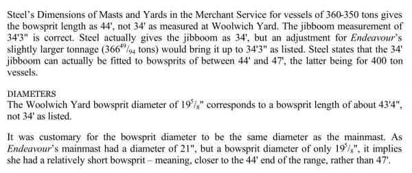
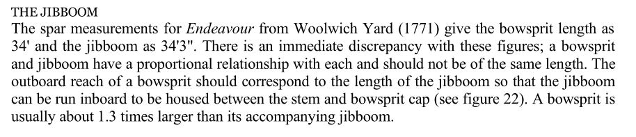
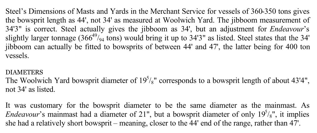
Hi guys Remember their are no exact plans of the HMB Endeavour. Whether the actual vessel had a 44' or 34' bowsprit ? By posting the above, I am interested in others views or other information available to support a bowsprit length. I am inclined to construct a 44' bowsprit because: a) I have not done the rigging yet in my limited knowledge of the period, I can only go by evidence available c) Functionslly, design wise, a 44' bowsprit would be likely d) but the bowsprit may of been shorter for a reason we do not know about. I wouldn't go changing it it was already built. I am fairly sure I will go for the longer, as my build is my interpretation of the Endeavour. Dave R
-
Good start on the 2nd layer planking Chris, After I tapered and beveled the edges of a plank... oh memories.... I used steam after soaking for a lot of my 2nd layer planks. I held the plank in place while it cooled down, worked good enough for me. Dave R
-
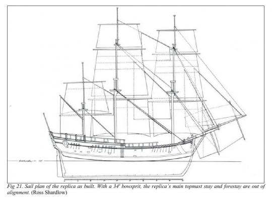
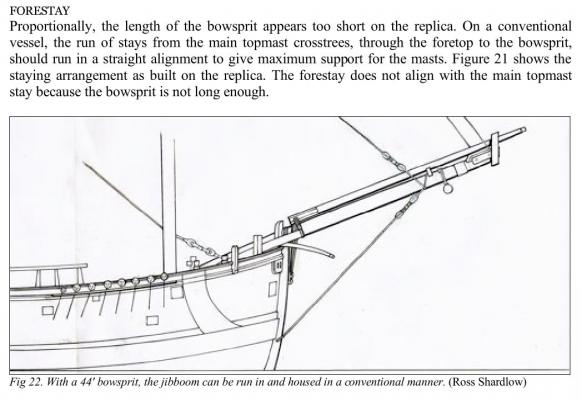
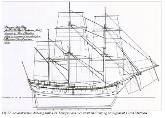
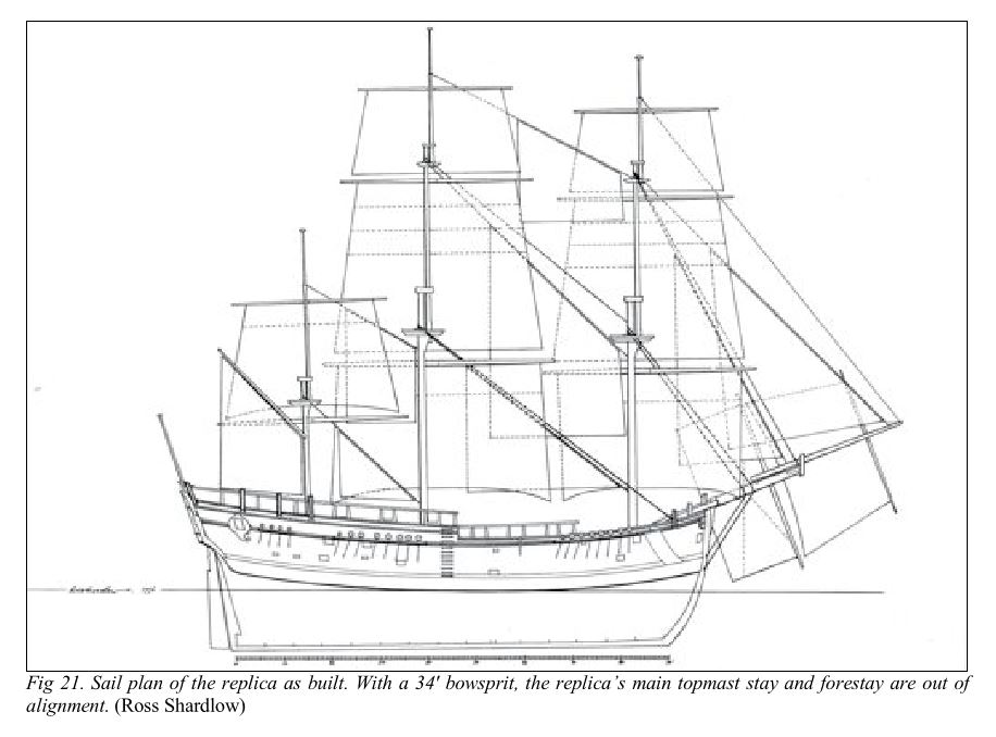
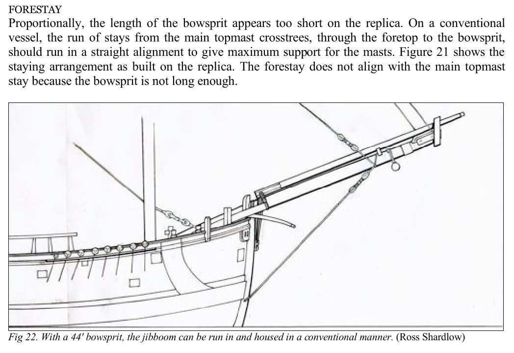
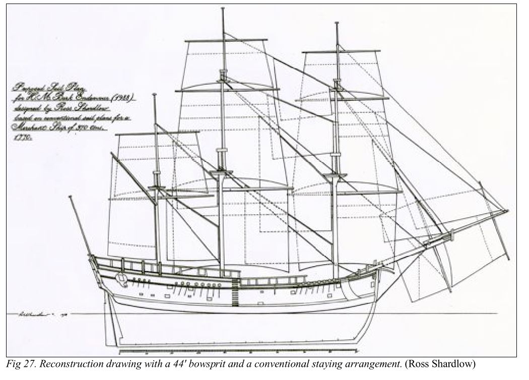
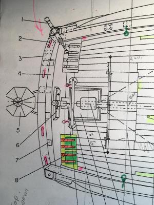
Hi all Model Endeavour shipbuilders. My shipyard has not started back to work yet in 2016. Something about, school has not started back yet. However I have been reviewing the documentation I gathered some while ago on the Endeavour, related to the masts/rigging. I found a report a Mr Ross Shardlow(artist) prepared some time ago(1994) relating to the Replica of the Endeavour. It dealt with “a Case for a Taller Mizen Mast” and also a case for “a Longer Bowsprit”. Whilst the report Ross prepared related to what some may say "shortcomings" of the Replica, it does way into some interesting design aspects of what we all construct. And I like details.. Have some of you seen this report. ? “a Case for a Taller Mizen Mast” I have no doubt most of the models we are constructing have the taller Mizen mast – some 10ft taller than the Replica. The Mizen cap is at approx. the same height of the Main top. This is what is indicted in Karl Marquardt ‘s “Endeavour, Anatomy of The Ship”. “a Longer Bowsprit”. The sketch below shows the Endeavour Replica with a 34’ Bowsprit. This is similar to that which Karl Marquardt indicates in the “Anatomy of The Ship”. The AOTS takes the Woolich Yard bowsprit length as measured from the Fore topsail sheet bits forward to the head. I believe that is correct. However the run of stays forward to the bowsprit are not straight. Ross however puts a case forward for a longer Bowsprit of 44’, whereby the jibboom can be run and housed in a conventional manner. We are also told there is a relationship between the bowsprit and Jibboom with ships of the erea. So the Sailplan with a 44’ Bowsprit would look like. Ross Shardlow mentions a couple of possibly reasons why the bowsprit is at 34’. How the bowsprit spare was possibly measured from the knighthead or rot around the stem head. However the compelling facts for a longer bowsprit for me are: 1. Having the ability for the jibboom to be housed fully on the bowsprit Fig 22; 2. Steel’s list a 44’ bowsprit, matches the 19 5/8” diameter of the Woolwich Yard bowsprit diameter; 3. The run of stays from the main topmast crosstrees, through the foretop(foremast) to the bowsprit is the conventional arrangement Fig 27. 4. A longer bowsprit is indicated in several engravings and depicted by Sydney Parkinson in his sketches; 5. The headsails would be further foreward, better for running with the wind. So what to do ? A 43’ Bowsprit (an extra 10’ = 50mm at 1:60 scale), this may not be too bad. Dave R