


JSGerson
-
Posts
2,649 -
Joined
-
Last visited
Content Type
Profiles
Forums
Gallery
Events
Posts posted by JSGerson
-
-
As I mentioned, I have no experience with square rigged sails. That being a given, going from 1:75 to 1:100 is a big difference (to me at least). Take a micrometer, and measure the thickness of the sail cloth and figure out what the scale thickness is. If it sounds reasonable, then use it. But, if scales to something like 2" thick sails, for example) I'd think about using something else. A thought just came to me. If you look at real sails, they are semi-transparent; you can see the shadows of the masts through them. What if you use grocery store plastic bag material. I mean the kind groceries are put it as you go through checkout. They are semi-transparent, very thin & flexible for the scale, strong, and some come in a light beigse canvas color, and you can glue parts together. Just a thought.
-
I have never installed sails as I have only completed one square rigged ship. My logic, with no experience to back this up, tells me to add the sails after all of the standing rigging is done. It's called standing rigging, because that is what is left when the sails are down. If there are any required blocks and other do-hickys (that's a technical term) needed for the sails that could be installed prior to the sails, those should be pre-installed.
Here's something to think about, you could install furled sails instead of the full blown sails (that's a play on words🙂). It would allow the viewer to see more of the ship's details but still have all of the running rigging. Think hard about what material you are going to use for the sails. Any cloth will be out of scale. The cloth will be too thick and maybe too stiff, the cloth weave too big, and any actual stitching on the sails, too large. I've seen model makers use fine cloth, silk, tissue paper (kind used on flying balsawood framed planes), and even thin formed plastic. It's all a matter of effect and the skill to pull if off.
-
You used the term “ballistic netting” That netting is used to hold the crews’ hammocks for airing when not in battle and as a shrapnel barrier during battle. So, I suppose the term “ballistic netting is somewhat correct.
Take a look at Post 224 Robnbill’s Mamolli Build 1:93 scale (close to Billings Boat 1:100) to see how it looks when filled.
As for order of rigging, that is a matter of personal preference and skill. I’ve only done one other square-rigged ship, the Rattlesnake (which you can use the link in my signature) and I followed the theory of rigging the ship as it would have been done for real. In that case, I partially rigged the bowsprit at its base first, then moved next to the mast steps from the fore mast, back to the mizzen, rigging those portions of the masts. Then to the next mast step up, interconnecting the mast as required etc. I was trying to work from closest to the mast outward towards the bulwarks to have the least amount of rigging interference.
Other builders build their mast completely off ship to have the maximum access to all the nooks and crannies. They assemble all three steps and place as much stuff onto the mast they possible can before installing the mast as a unit onto the model. This creates a lot of loose rigging hanging from the masts which must be meticulously tracked and not get them tangled.
In both cases the yard arms were built off ship. I left mine loose held in place as would they be on an actual ship. Others pin the yards to the mast. Some people work stern to stem, some stem to stern. There is no “right” or “wrong” way. How am I going to rig my Conny? Probably some combination of all methods.
-
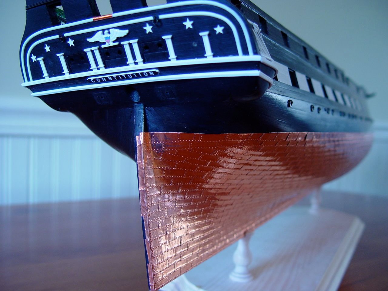
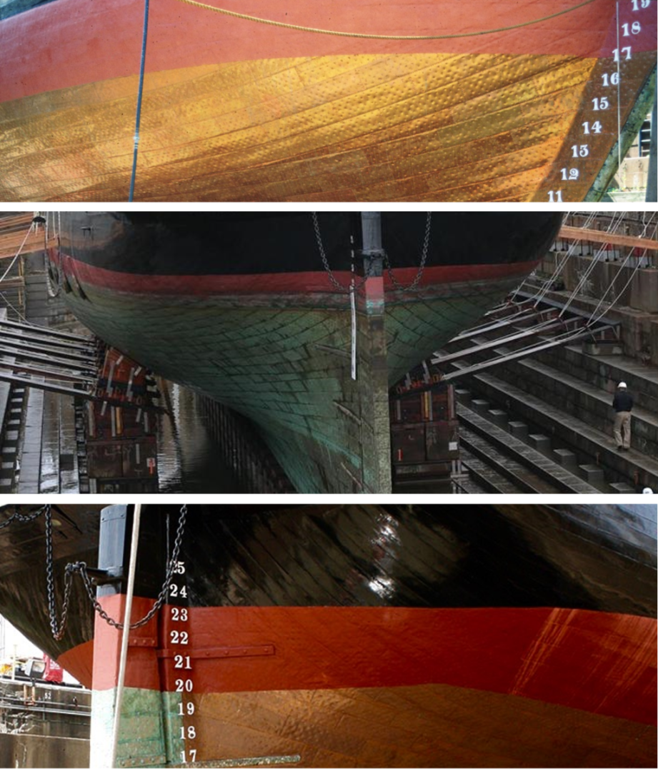
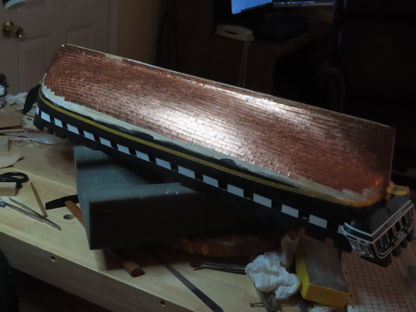
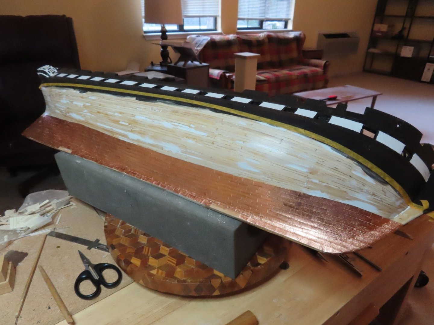
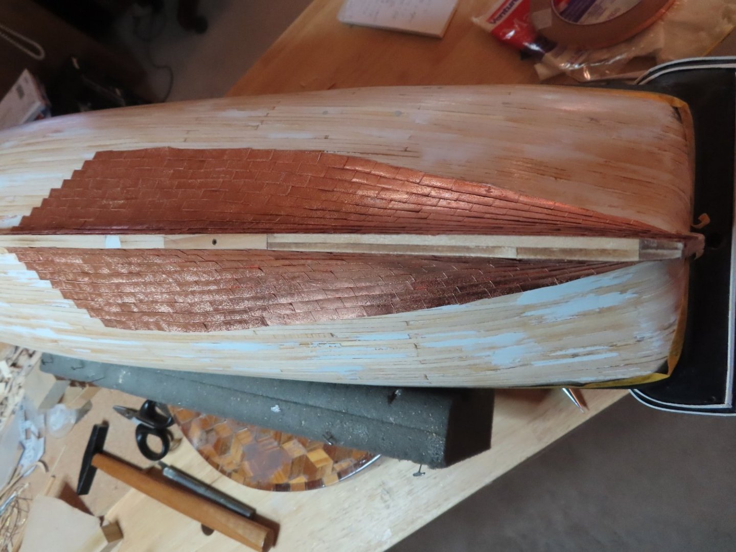
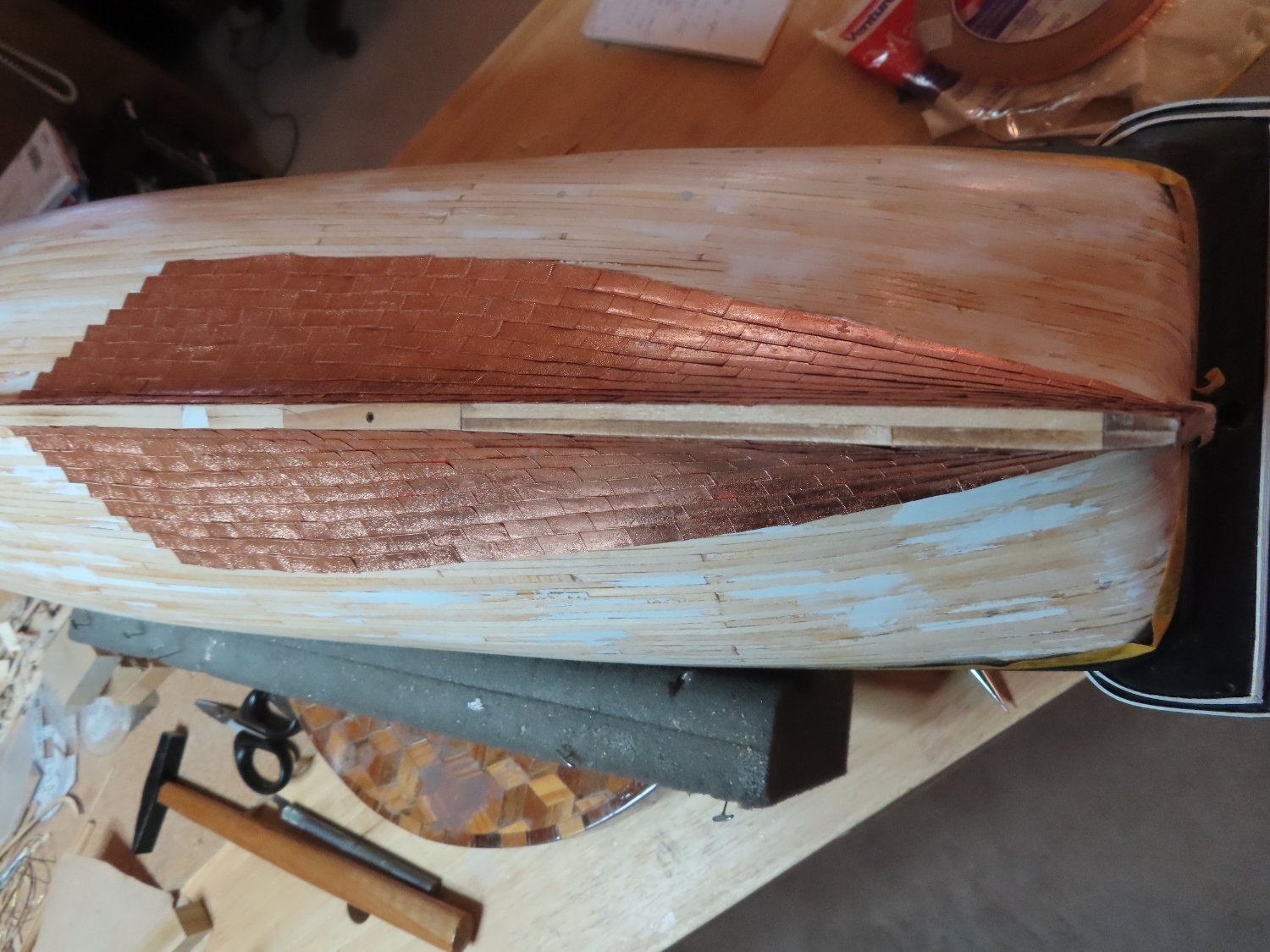
Now I am approaching the top edge boundary of the plating. Up until now I had been using Robert Hunt’s practicum as a guide to perform this task. His plating method used a double capping row to end his coppering. This method is shown in numerous guides as one method which copper was done, but not the only method. The actual ship, it turns out, uses a different method, at least it does currently. It may have used different patterns in the past, but since my model reflects the current version for the most part, Mr. Hunts method is incorrect for the current method as you can see from the pictures below. I had started to create the double copper capping row but ripped it out when I realized the discrepancy. I still have about 3-4 hull rows to the water line, plus the stem, keel, and stem edges as well as the rudder, to plate.
-
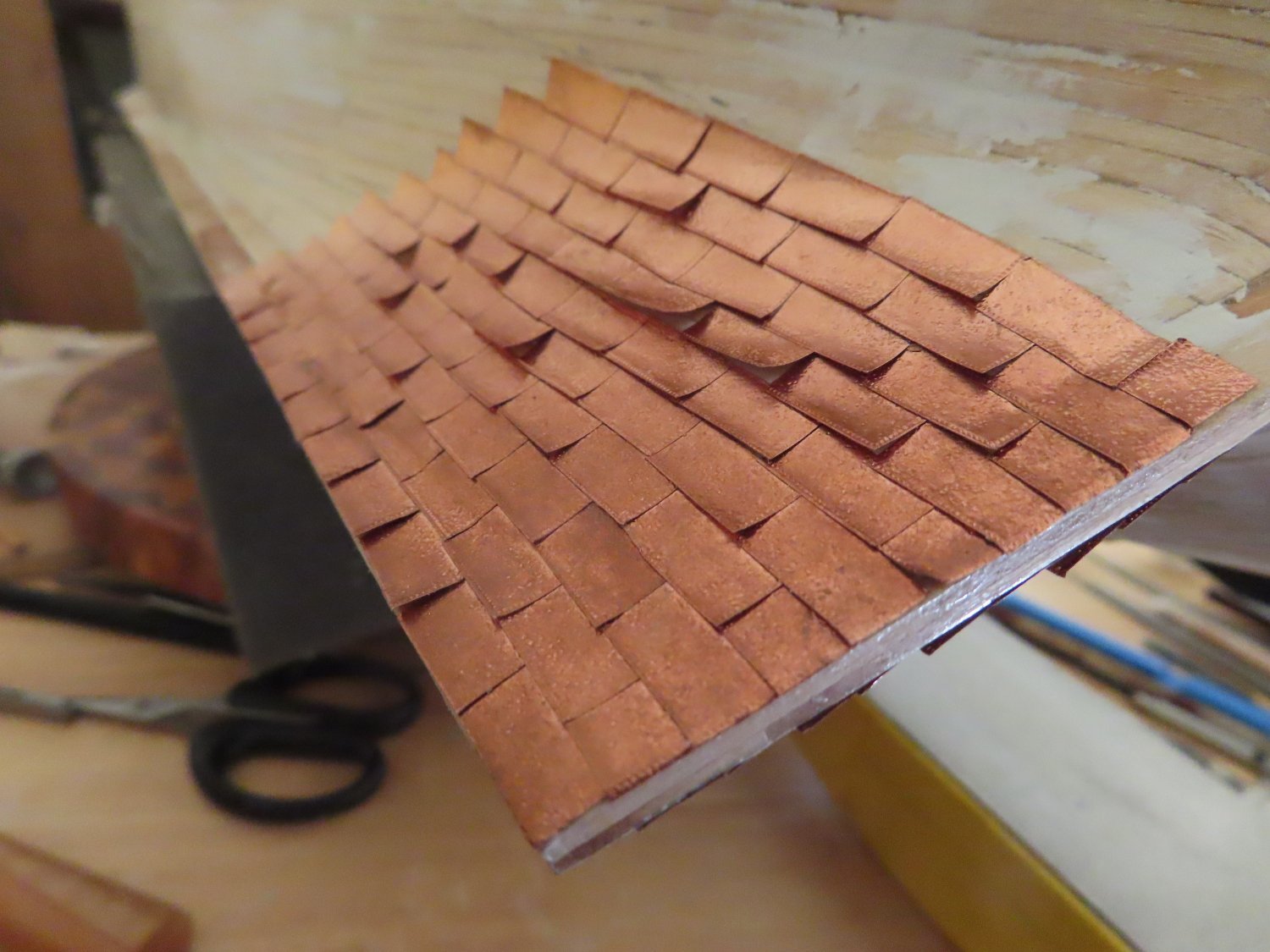
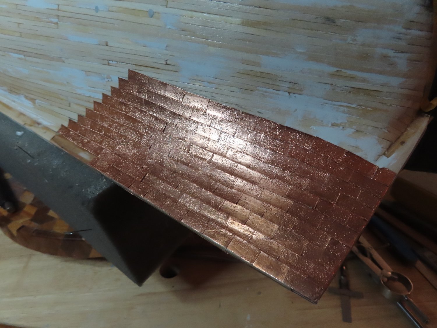
Still in the routine of cutting up about 20-25 plates at a time, embossing the face of the plate with the sandpaper and the fine teeth of my miter saw on two edges then placing, and finally burnishing the plates into position. After about 40 to sixty plates, I’d quit. I couldn’t take any more. Before I could add any additional plates the next session, I’d have to CA glue all the plates that curled up not sticking permanently. That is a pain.


-
Welcome to the world of model ship building. It's invariable that kit parts are not accurate, not provided, poorly made, etc. As a result, you end up making your own details and gaining skills along the way. Things like blocks, miniature rope, eyebolts, rings, and other rigging items I sometimes purchase from third party suppliers, or if that fails, attempt to make them myself. Knowing what something is suppose to look like is a tremendous help so I have a vast library of images I've accumulated of the years, of nautical details, as well as books, and "how-to" articles I've gleamed from other build logs from which I can follow. There is a lot of stuff on YouTube too.
If I were to make the chain plates, I might use thin copper or brass plate, cut into strips. At those thicknesses, a pair of sturdy scissors or a stout knife and rule could do the job. Then punch the necessary holes with an awl, nail, or heavy needle; smooth out the hole edges, and bend to shape. Finally, use some blackening agent on the metal. Paint is too thick and doesn't look right.
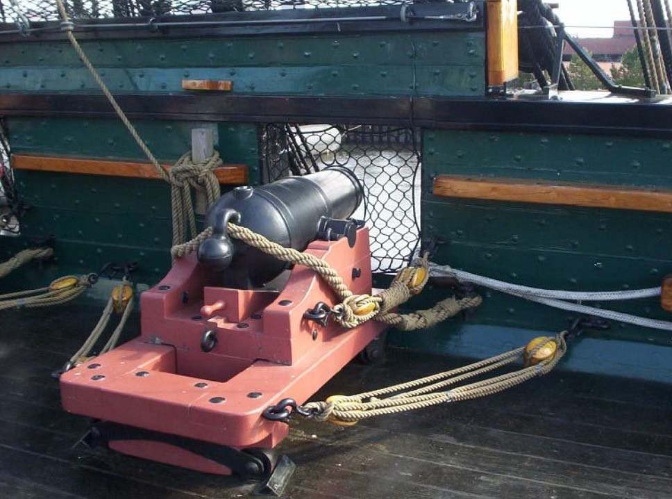
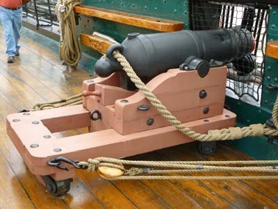
As for the color of the carriages, they are red not orange. I don't know the official color name but I would call it "redwood furniture" red. The bright sun affects the color in the images.
BTW, I'm still learning too.
-
Out of curiosity, what method of adhesive did you use for the stanchions, epoxy or silver solder? How did you hold the pieces in place as you joined them?
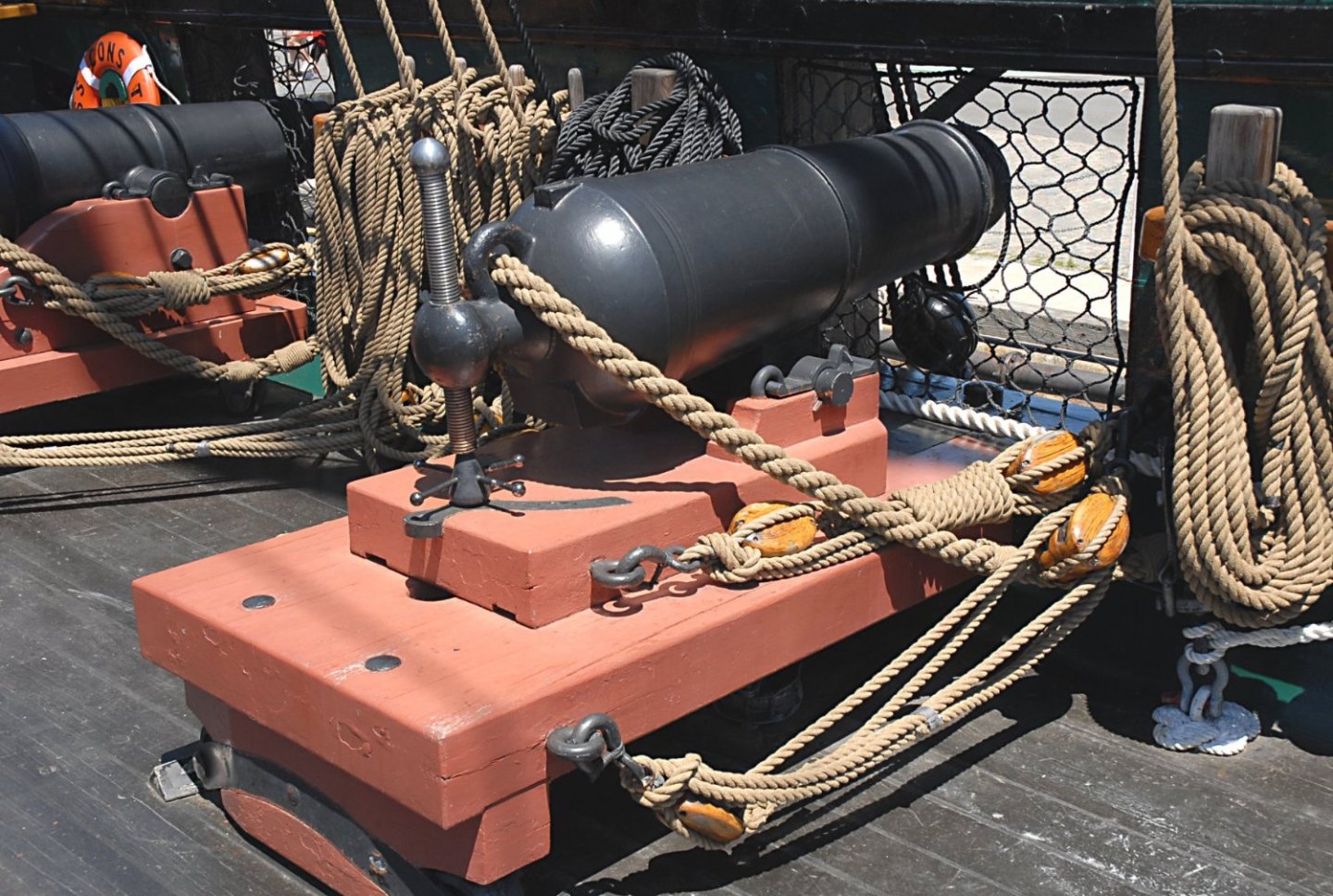
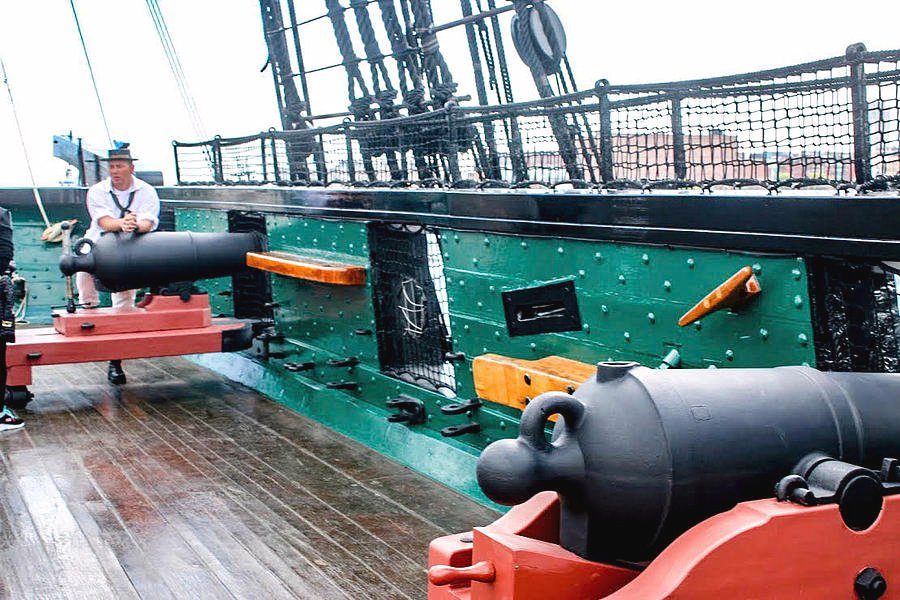
You stated: "I don’t like the fact that the cannons are not on wheels in my kit..." Technically most (not all) of the guns on the spar deck are cannonades and have a different type of carriage to hold the short barrel gun than the traditional long barrel gun carriage. The back wheels are small and are tucked under the carriage allowing the back end of the carriage to move side to side. There are no front wheels as the carriage rests on a pivot pin so the gun can be swung left and right. Presently, there are two types of replica cannonades on the actual ship today. The one with the vertical angle adjustment screw is more accurate than the more abundant gun with wedge adjustment. The images I've provided show the rigging. A lot of modelers elect not to include a lot of the gun rigging due to scale.
- CiscoH, Bill Morrison and Oldsalt1950
-
 3
3
-
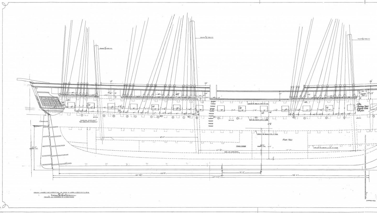
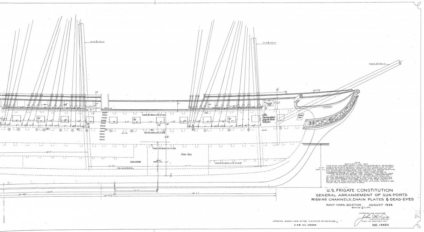
I have no idea if your measurements are correct but hopefully these plans from the US Navy (which are available at the USS Constitution Museum website) will help.
Jon
-
-
If you go to the USS Constitution Museum site, you will find a lot of US Plans of the ship. I found one that may help you with the bow bumkins.
Jon
25175 - Deck Framing Forward of Stern and Fore Tack Bumpkin.pdf
-
I decided to take the "easy" route and make my model based on the 2015-17 restoration. I say "easy" because of all the photographs that have been taken and accessible through the internet. Most builders who choose to create a historical version have to rely on contemporary paintings and models (e.g., 1812 Issacs Hull Model). Most often they choose the 1812 version. I need to see what I am modeling, so I'm making the contemporary version. The Model Shipways kit is based on the 1927-31 restoration. So, the obvious thing I had to do was remove the Top Gallant rail and add the waist. The 2015-17 restoration also removed the bow rail. Of course I won't be adding any tourist enhancements (gun port nets, speakers, etc.).
BTW, silver soldering is done with a small torch as opposed to an iron. You can see how it's done on You Tube. Usually the videos are posted by jewelry makers, but the process is the same. My Conny is the first time I ever did silver soldering.
Jon
-
I've got a long way to go before I get to the stanchions (cages) so my thoughts are conjecture . All of the methods I've seen used silver solder (which I plan on using), which isn't too difficult...relatively. The solder sets quickly, and can be removed to start over if needed. However, the only other method I can think of is epoxy. Like solder, it will require removing excess joint material, shaping the joints, and in the case of epoxy, painting the epoxy joints to match the brass work. I don't think this method is any easier; more likely be harder. Don't know if this helps, but it's all I got.
Jon
-
My philosophy on details and accuracy is simple. I like detail where the closer you look; the more detail is revealed. What most of us are making are models, not accurate miniature reproductions. Things like tree nails that I added on my Rattlesnake hull and deck, I did not accentuate their presence by increasing their contrast so you could see them better. From a foot away, the casual observer would not see them. Get closer, the detail reveals itself. On the real ship they blend in with the background wood. I got the detail and some of the accuracy.
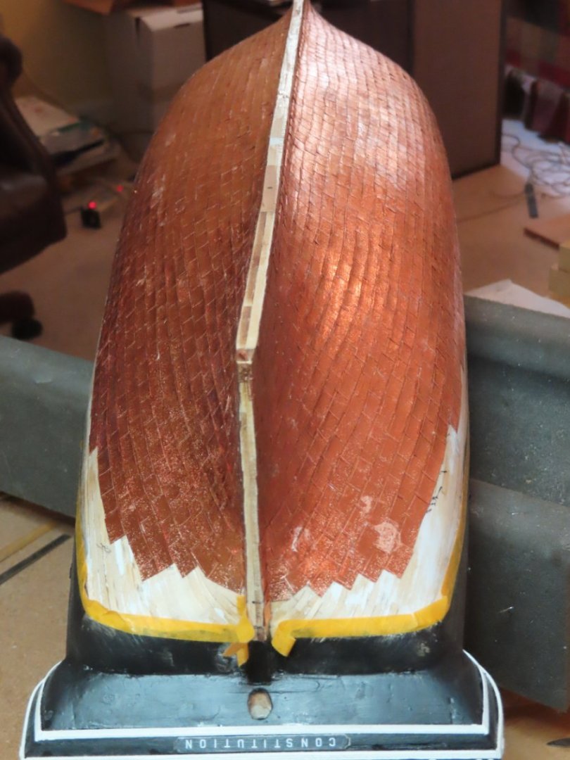
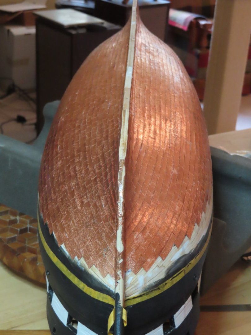
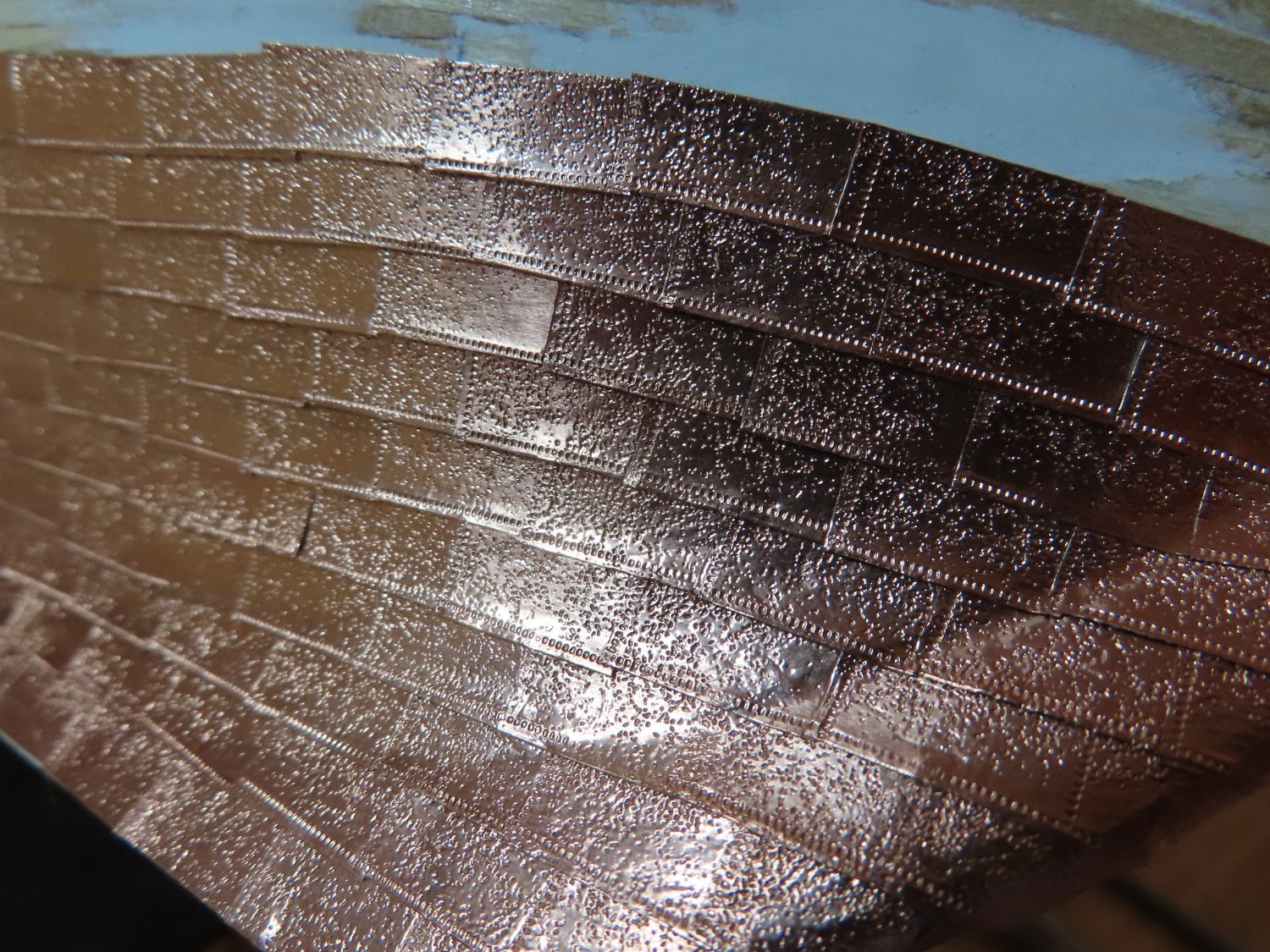
On my Constitution there is no point for tree nails, the scale is too small and everything is painted. I am copper plating the Constitution’s hull with individual copper plates, but I total ignored the copper plate nail pattern found on the actual ship. The detail is too small for the scale, but I tried to give the impression of nails in the plate. I embossed the plates with rough sandpaper, so the plates are not shiny mirror smooth and give the impression it is covered with copper nails. Sometimes I do add detail that the typical viewer would not see (“for God’s eye”) because it was just fun to do, I try to balance the effort of creating that detail versus the chances of actually seeing it on the model. If it’s “easy and fun” to do I might add it. If it is difficult, probably not. I provided enough detail (hopefully) but not all on the gun deck furniture so that when viewed through the (planed) selected opened planks of the spar deck, the observer will get a sense of what it looks like below decks. The builder is the master of his model world. If it pleases him (her), then it’s good enough.
-
Brian, I have personally collected over the past 10 years approximately 19,000 images (organized in my particular manner) of the USS Constitution, from a variety of sources, covering most of her photographic history. I'm still building my model, so I am still collecting. Should you or anyone else need images of a particular view, angle, item, etc. of the USS Constitution, there is a good chance I may have something to help you.
- Brian Falke and mort stoll
-
2
-
Very nicely done! I suspect of all of the attributes you listed, ...
QuoteWith the lamp, perseverance, focus and some salty seaman’s language, I got the other four rigged in less time than it took to rig the first one.
..."salty seaman's language" was probably the easiest to learn 😁
-
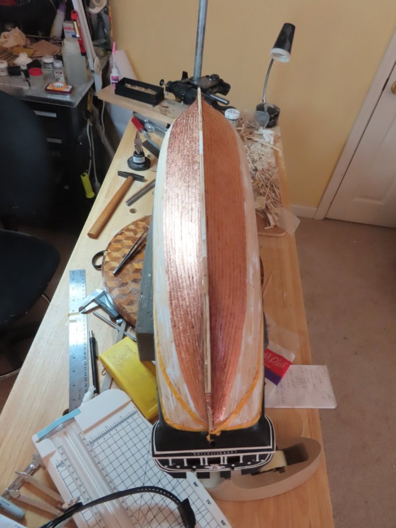
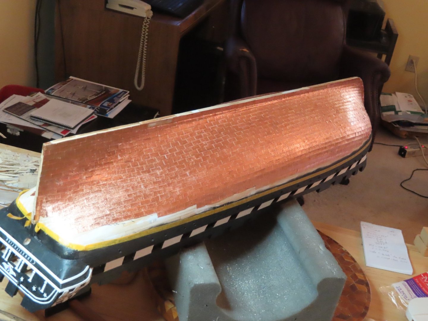
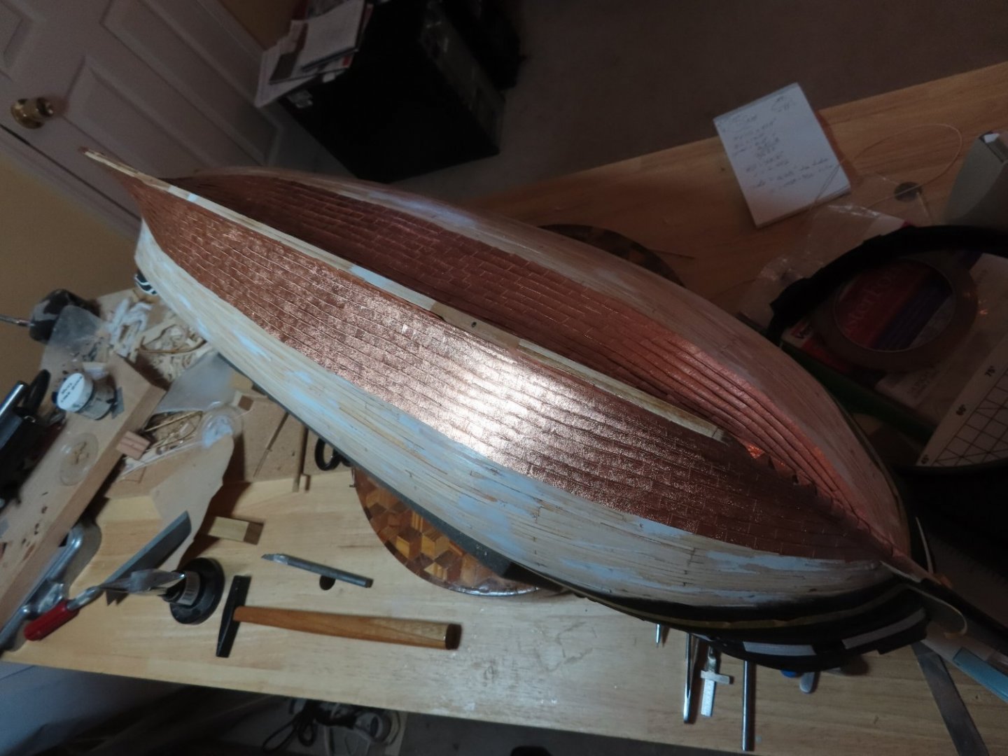
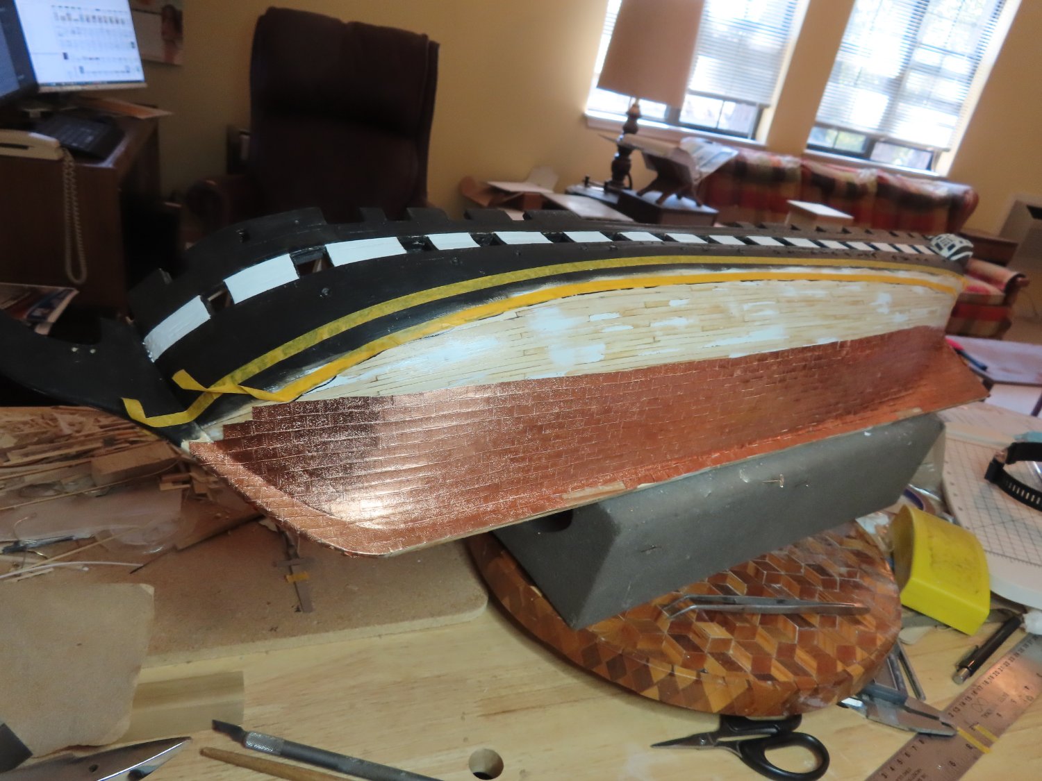
Progress report on the copper plating: I believe I am approaching the halfway point, if not already on it. If you look closely, you may notice two areas of the keel where the sides are not covered in copper. I left those aeras untouched so it can be identified as the places I used wood from the actual ship. Also, I have not yet plated the bottom of the keel.

- GrandpaPhil, robdurant and KurtH
-
3
-
-
Avi, I already tried that. See May 23, Post #159
-
Quote
I’d be happy to. I don’t think this build log is the right place for it. Is there a better thread, or some good place to upload them?
I queried Model Ship World to see if there was some sort of a Photo Reference Library and if not, why not. They said there wasn't:
Quote"The most likely reasons are
- no one has asked for one (or at least very few people have asked), and
- it would probably entail a not insignificant amount of work for an MSW staff member.
On top of those two reasons, sharing photos gleaned from the internet often constitutes some form of IP infringement.
So the best place to post any of your images is your own build log. I hope you do."
Jon
-
Has anyone started a photo library of reference material for specific ships, say USS Constitution for example. I've got thousands of images I use as reference material for the Constitution that I gathered from the internet as well as pictures I shot. Some of us would like to share photos we've gathered and pool them into categorized and organized library of sorts but outside of a specific builder's build log. If so, where is it. If not, why not?
-
Avi, up until the late 70s, I lived in the suburbs of Boston and enjoyed a lot of the amenities of the city, among them visiting the USS Constitution. I got one last in person look at her just before her last restoration. I have amassed a large library of images of the ship which I'm willing to and have shared with others for the asking, but I am always looking for new images, different angles, those little gems of details that help me with my model. Unfortunately, I don't have a lot of images of her since the 2015-17 restoration. Would you be willing to post your pictures so the rest of us can enjoy them too?
Jon
- Bill Morrison and mort stoll
-
2
-
Progress as of May 10, 2022
- GrandpaPhil, Prowler901, Robp1025 and 1 other
-
4
-
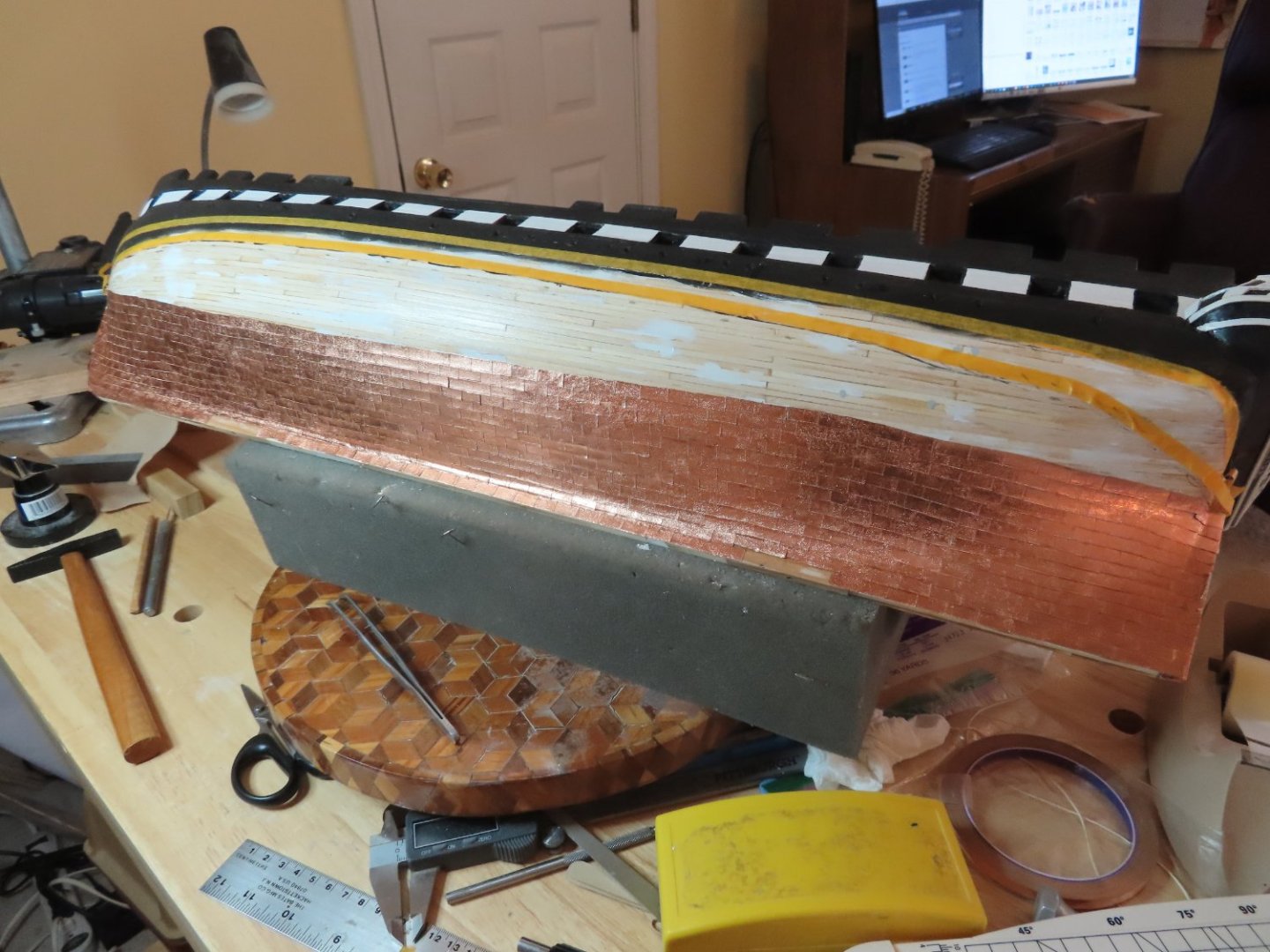
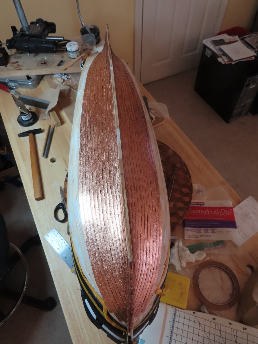
A week or so into copper plating and all is going slow (my usual pace) with decent results. I did run into one annoying problem – the plating wants to lift up even after multiple burnishing. I burnish by rolling a short 3/8” diameter wooden dowel over the copper tape. I want to flatten the embossing, not rub it out. With carefully applied CA glue under the plates that lift, I gotten most of them to stay down. So it’s two steps forward and one back. The pictures below show only one side although both sides are being plated at the same rate.


- KirbysLunchBox, KurtH, Robp1025 and 2 others
-
5
-
Your Conny is looking good.
Sounds like your surgery was successful. I know exactly what you are going through with your back. I had back surgery in 2019. Eight hours on the table, and numerous screws and pins later, I feel better. I have some loss of flexibility due to the lower back vertebrates being fused, but for the most part, I'm pain free. This was my second surgery, the first one was 40 years earlier. If this one is half as good as the first, I'll be very happy. I hope yours lasts a long time too.


USS Constitution by JSGerson - Model Shipways Kit No. MS2040
in - Kit build logs for subjects built from 1751 - 1800
Posted
2,500 or so Copper Plates so far
My copper tape roll ran out 24 plates shy of completing the hull. However, I was prepared as Hunt’s practicum warned me that may happen, and I also read the same accounts in a couple build logs. This did not include coppering the stem, keel, stern, and rudder. Also, it was not unexpected that the oxidation color of the second roll of tape was of a slightly darker hue. Over time they will even out going from shiny new copper to old penny brown, and finally green copper oxide (if the model lasts that long).