


JSGerson
-
Posts
2,481 -
Joined
-
Last visited
Content Type
Profiles
Forums
Gallery
Events
Posts posted by JSGerson
-
-
Quarter Gallery Interior
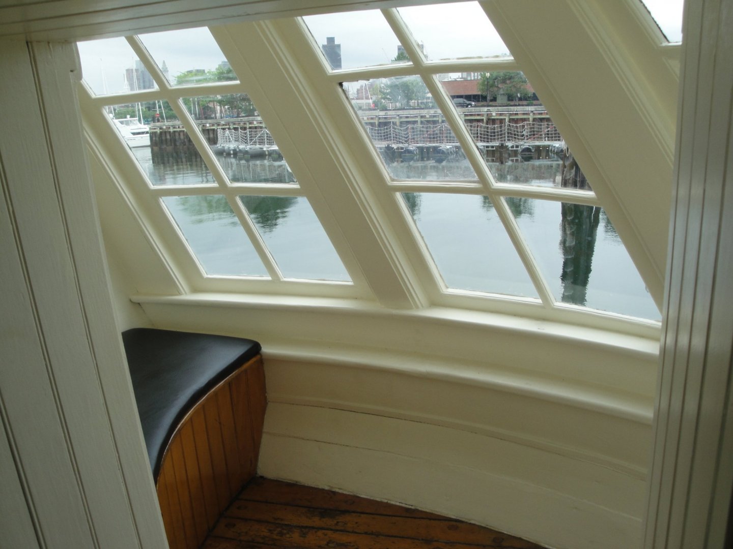
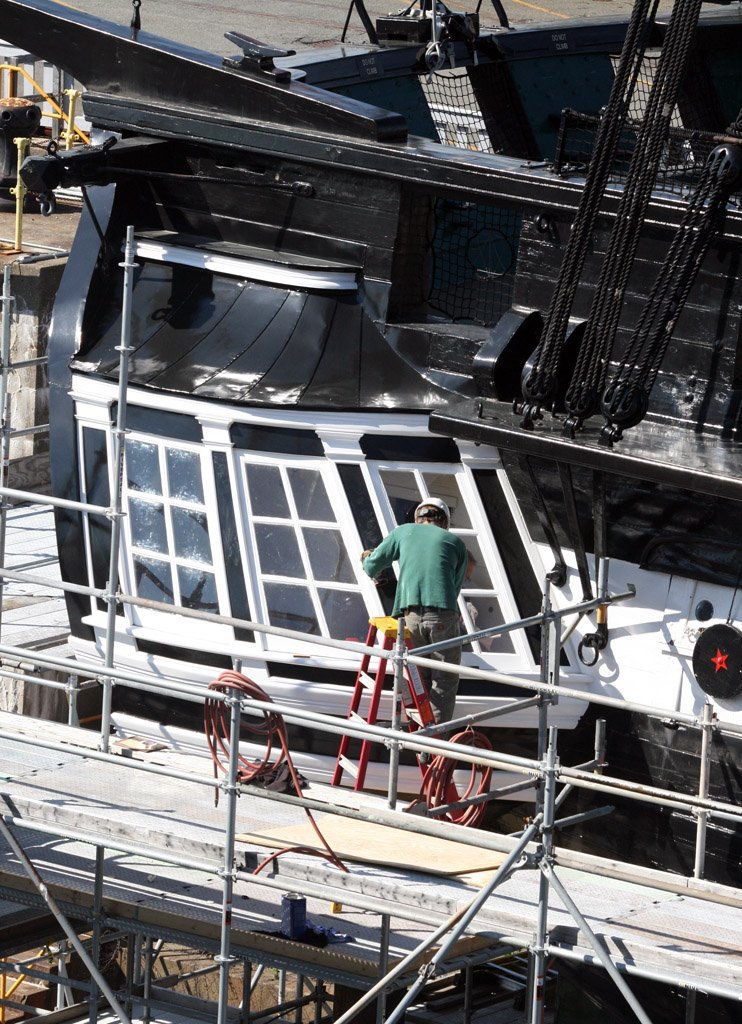
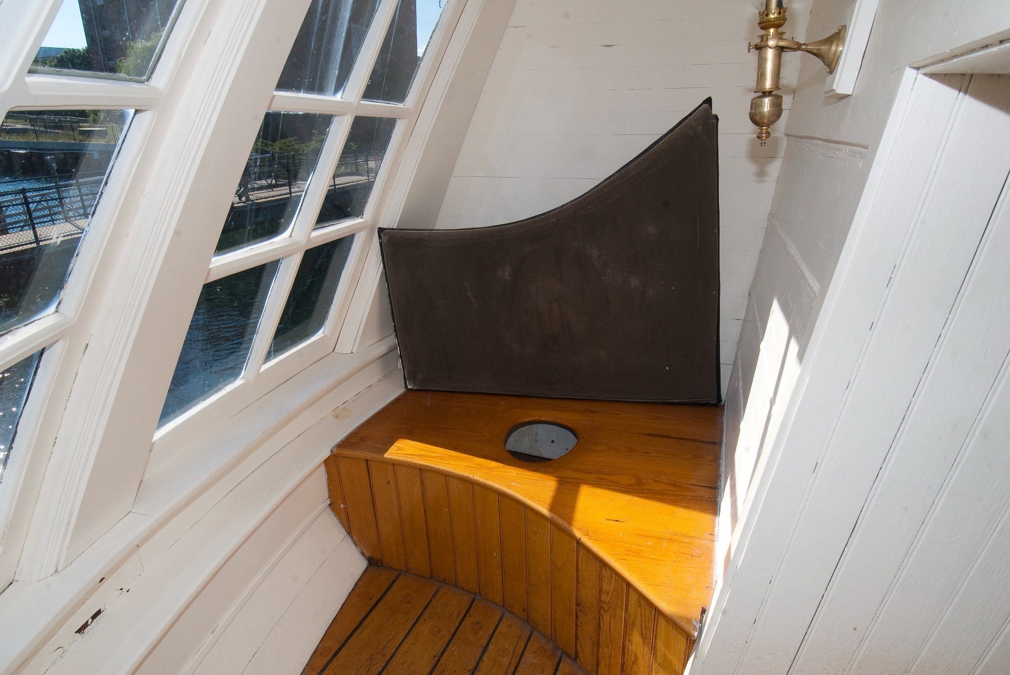
Nobody, as far as I know has attempted to place anything inside the quarter galleries. So here I go again. In the practicum there is a photo (HP7.2.5.-1) of the port quarter gallery annotated with numbers for the instructions of the practicum. It also shows that the interior of the quarter gallery can be seen by an outside viewer. What can be viewed is a bench seat, which on the starboard side lifts to reveal a privy, and a wall sconce light. The bench seat is easy to make, the sconce is not. If I was adding interior lighting, I might have considered it, but since I have no electrical skills, the light is out (pun intended).

- Robp1025, GrandpaPhil, CiscoH and 1 other
-
 4
4
-
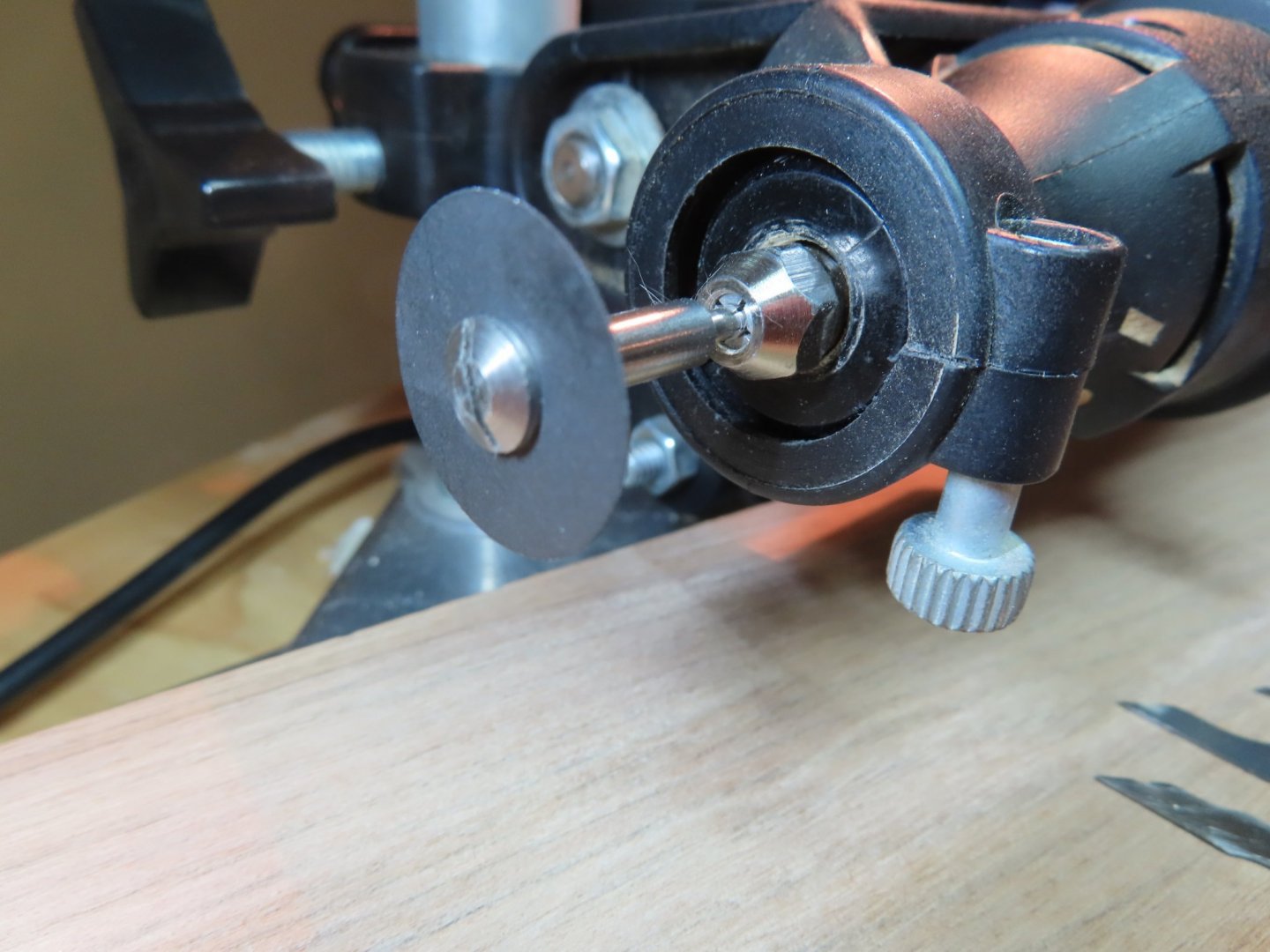
Glad I was a bit of inspiration for you. My biggest problem is seeing that close. I physically have to get my nose within a few inches of a spinning disc that could explode due an in-opportune hand movement. I need to wear head mounted magnifiers and lights to see that close which provide eye protection, but those cutting discs are very fragile to tiny lateral forces. I broke one already just moving my work piece into position and just touched the disc. Luckily it wasn't spinning at the time. An X-Y table gives you a lot more precision. Mine just doesn't have the expanse of movement I need. I hope you can work it out. When you get your X-Y table set-up working, please post it.
-
Once I made the molding, I had all my parts for the quarter galleries’ roof. The roof molding was cut and painted first. Using the gallery spacer block, the roof pieces were glued into place level with the gallery floor. Touch up painted was added to the remaining exposed transom wall. Finally, the roof molding was added to the roof. So far, so good.


-
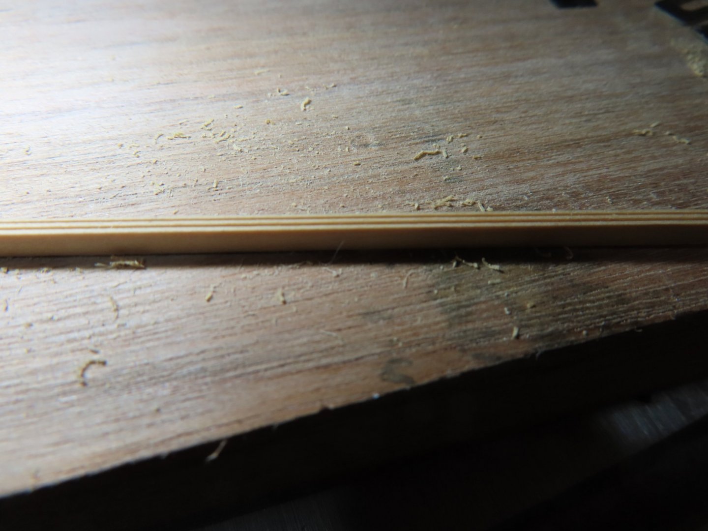
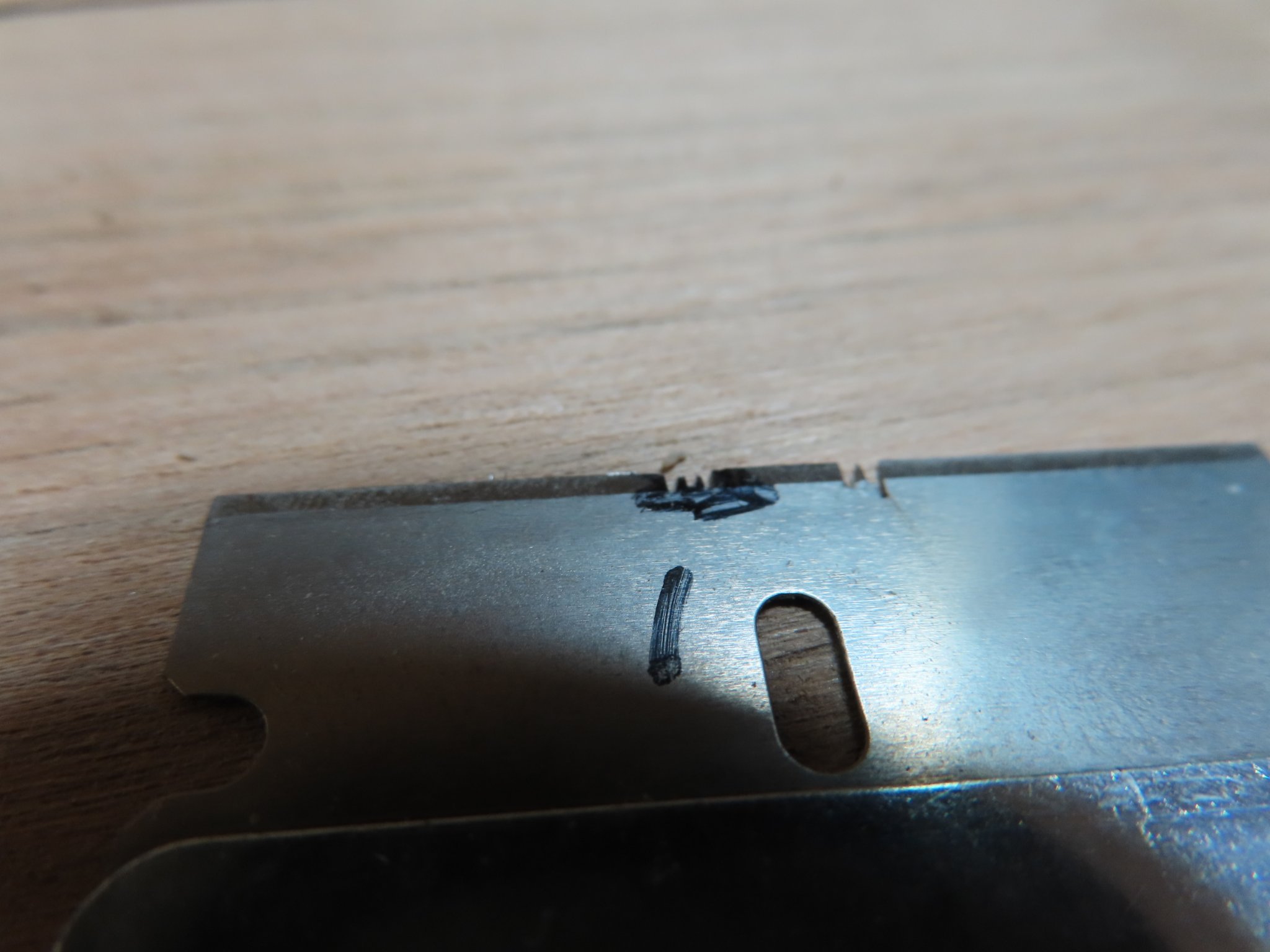
Continuing with trying to make a decent scraper, I had marked the blanks (initially used old X-acto blades till I ran out, then switch to single edge razor blades) with a Sharpie to indicate where to cut. The sharpie markings were in turn scratched with a pin showing the planned profile. I have a limited number of ultra-thin, and very fragile Dedeco International cutting discs. What I lack is a steady hand and good eyesight. The spinning cutting disc cuts extremely quickly; one twitch and you've over cut or cut the wrong area and at worst, the disc shatters. In an ideal world, the scraper blank would be held fast to an X-Y table for precise cuts. My tools don't have that capability, so I'm forced to move the scraper blank by hand. It took some practice and luck, but I managed to make a reasonable scraper. Creating the molding with the scraper should be the easy part.

-
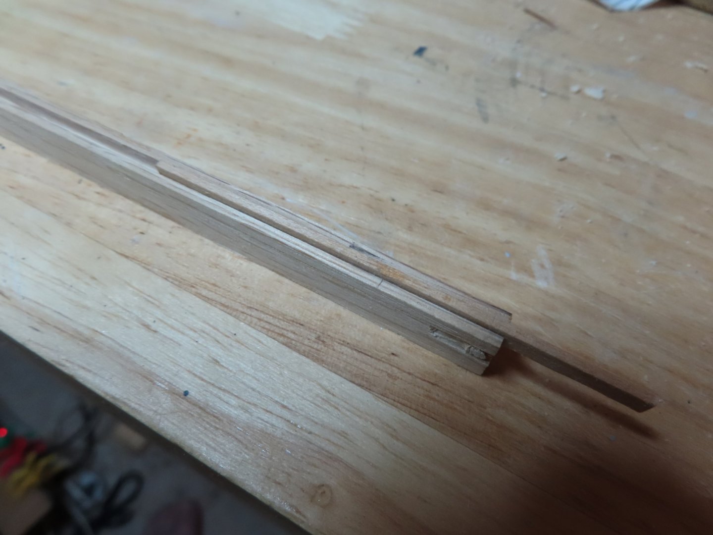
I then switch over to the thinner, more fragile disc cutter to try again. I got a better profile but not great. Those scrapers are a hit or miss for me. I’ll keep at it and hopefully, practice will make perfect, or at least something more acceptable.
- Robp1025, JeffT, GrandpaPhil and 1 other
-
4
-
Except that it didn’t work. There is no micro adjustment for the vertical position of the Dremel tool mount. Getting it to the proper height was a pain. Once I finally got that set, the boxwood was put in the slot, and it slid beautifully. However, there was a smidge (that’s a technical term) of space between the wall of the slot and the boxwood. Although the space was just less than the width of a piece of copier paper.it was enough to allowed lateral movement as the boxwood slid along the slot making the cut groove meander. If the slot was any tighter, the boxwood would not slide easily. Then there was the Dremel drill press mount itself; it had a minute wobble to it that it also contributed to the wandering groove. My idea was fine, my tools however lacked the necessary stability and tolerance to make it work.
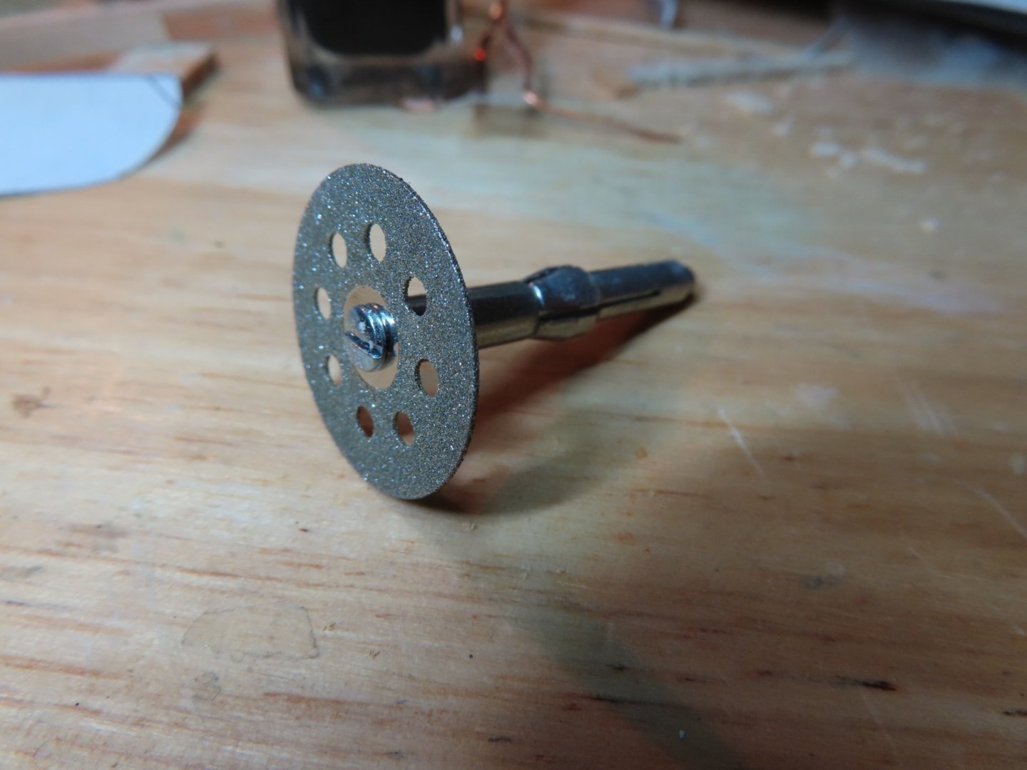
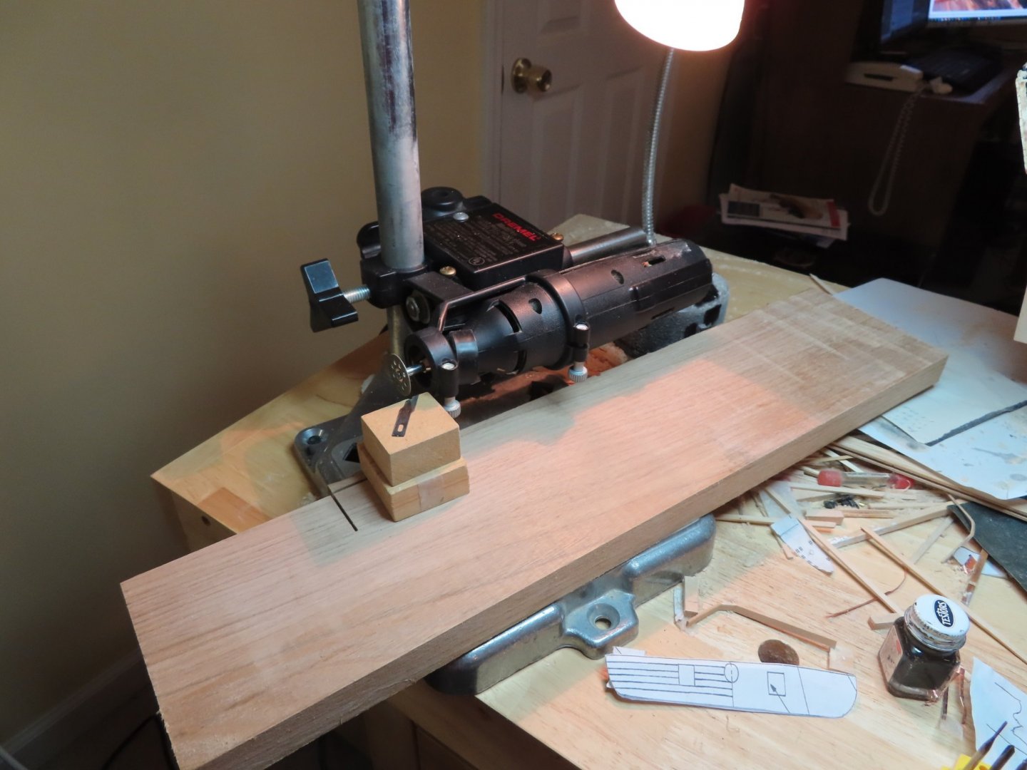
Back to the cutting disc. In addition to fine cutting discs, I also had a Dremel diamond cutting disc which I tried first. After removing the X-Y table and remounting the drill press stand to horizontal mode, I just stuck a hunka-chunka (another technical term) piece of wood on the drill press base. I couldn’t use the X-Y table because the tip of the Dremel tool was now outside its area of operation and my piece of wood was too big. On top of the large piece of wood I stacked two smaller pieces (stuck together with double sided tape) to raise the work area as the Dremel tool would not go any lower.
Using old X-acto blades for my blank scrapers I tried cutting my first profile for the quarter gallery roof top molding. The molding is only 1/16” wide and I wanted to get two grooves. Using the Dremel cutting disc didn’t work as it was just a bit too thick. I practically had to put my face within inches of the high-speed cutting discs just to see what I was doing. The depth of field of my optic head band is just fractions of an inch, not to mention the visual magnification distortion. I got a working scraper, just not the one I was trying to get.
- JeffT and GrandpaPhil
-
2
-
As us Conny builders know, there are several moldings on the quarterly galleries and elsewhere. One of my nemeses (among many) is making the scrapers to form the moldings. I have yet to produce one to the proper width and profile. I have fine cutting-discs that I bought when making the Rattlesnake as it was part of the instructions, but they are very fragile and not cheap. You twitch, and they shatter; not good if your face is just inches away. So, I tried a new method. I cut a slot into a length of wood just wide enough so that a strip of 1/16” wide boxwood would slide along its length. The slotted piece of wood was then mounted with a drill press vise on an X-Y Table on my Dremel drill press so that the sliding boxwood would move just below a diamond cutter on the Dremel tool. As you push the boxwood through the slot, the cutter would cut a groove. Easy, peasy.
- GrandpaPhil and JeffT
-
2
-
Mr. Hunt addressed the issue of detail:
Quote“And as all of the other ship details are added, less and less of these little details become noticeable at all. I added a wealth of interior details to my Fubbs model and have had dozens of people view it and they never get noticed, even when I point them out to people. So, I’ve concluded that it’s just not worth the trouble.” Chapter 7.2.2
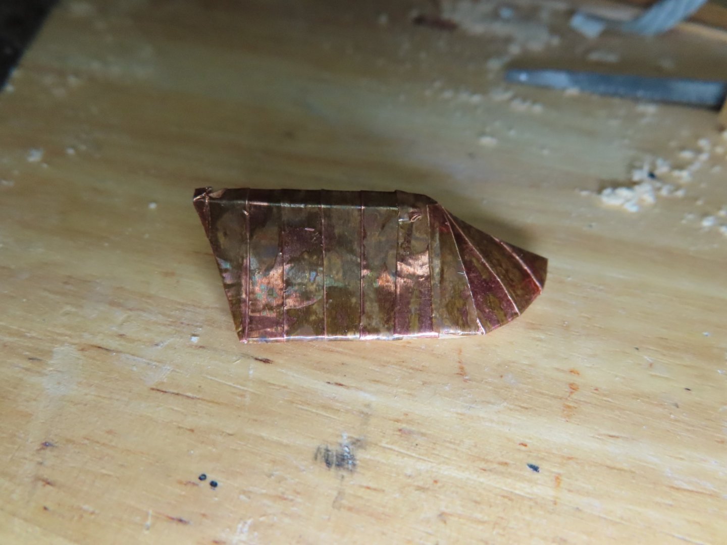
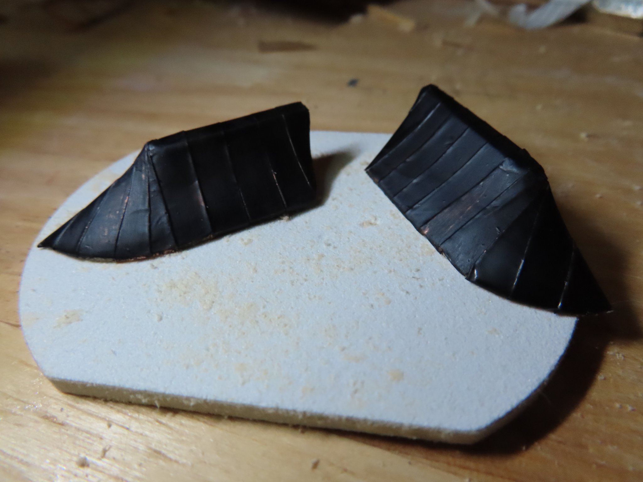
There is nothing wrong with what he states, but I’m not building my model based on what others will see or not see. I’m building it for me and if only I and the “man upstairs” can see it, so be it. Of course, I must balance that stance with practicality. How much satisfaction am I attaining if the detailed is buried with how much trouble is it to construct it’ That’s why I didn’t add some detail on the stove for example. I may be crazy, but I’m not that crazy (am I?). So, all that said, I decided to make the gallery roof look like it has a copper roof by giving it a copper roof, then paint it black. All that will remain (hopefully) are the subtle copper seams.
Because the practicum warned that the copper tape supplied with the kit may not be enough to fully plate the hull, I had purchased an extra roll sometime back. That is why, the coppering of the roof is not bright and shiny because I used the top layer which was exposed. It gave the roof a nice patina, but unfortunately I had to cover it with paint.
I did a painting test to determine which type of black paint to use on the copper, enamel, or the kit’s acrylic paint. As it turns out, both covered the copper about the same, but the enamel was more scratch resistant, so enamel it was.

- oneslim, Robp1025, usedtosail and 7 others
-
10
-
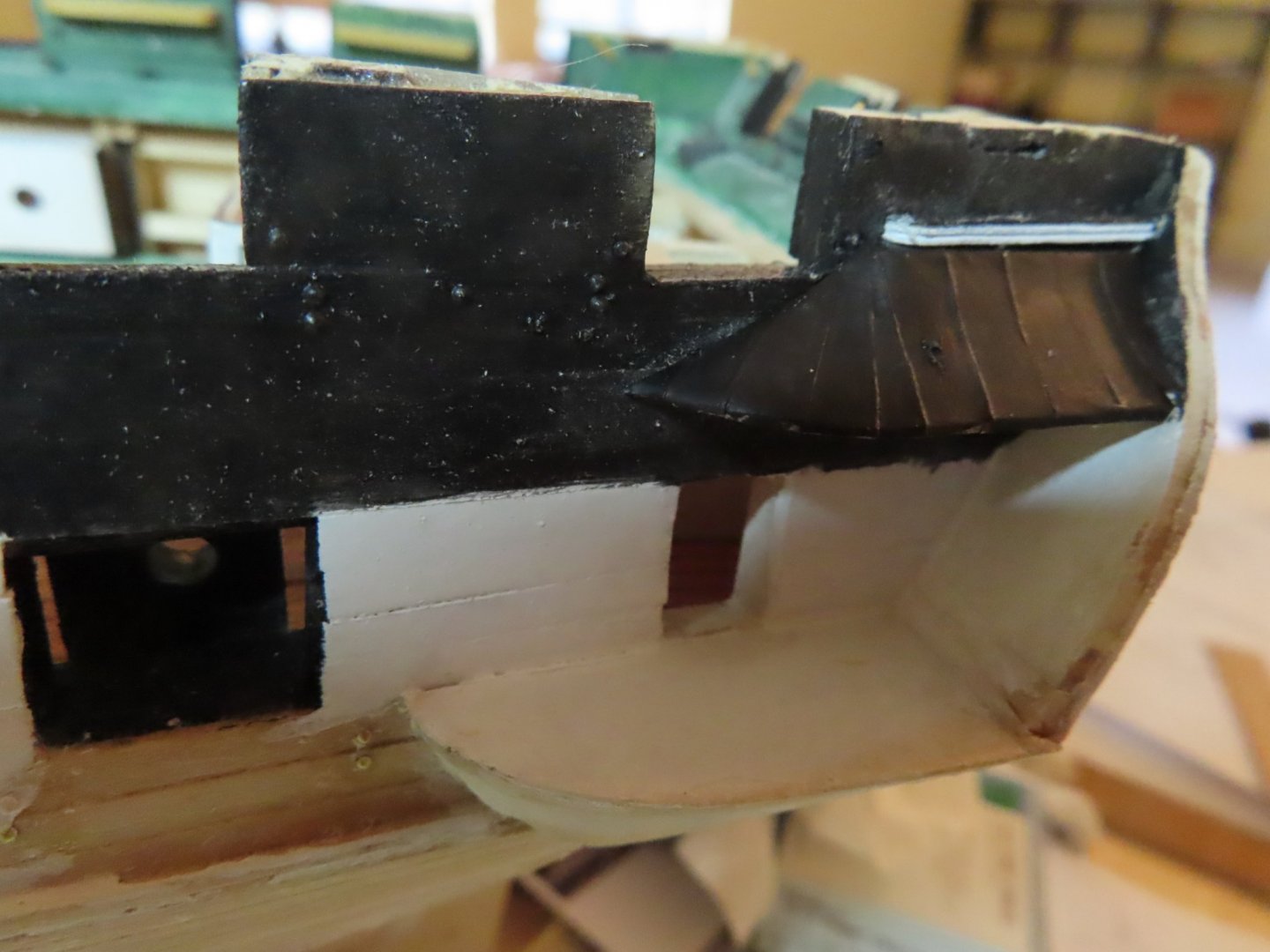
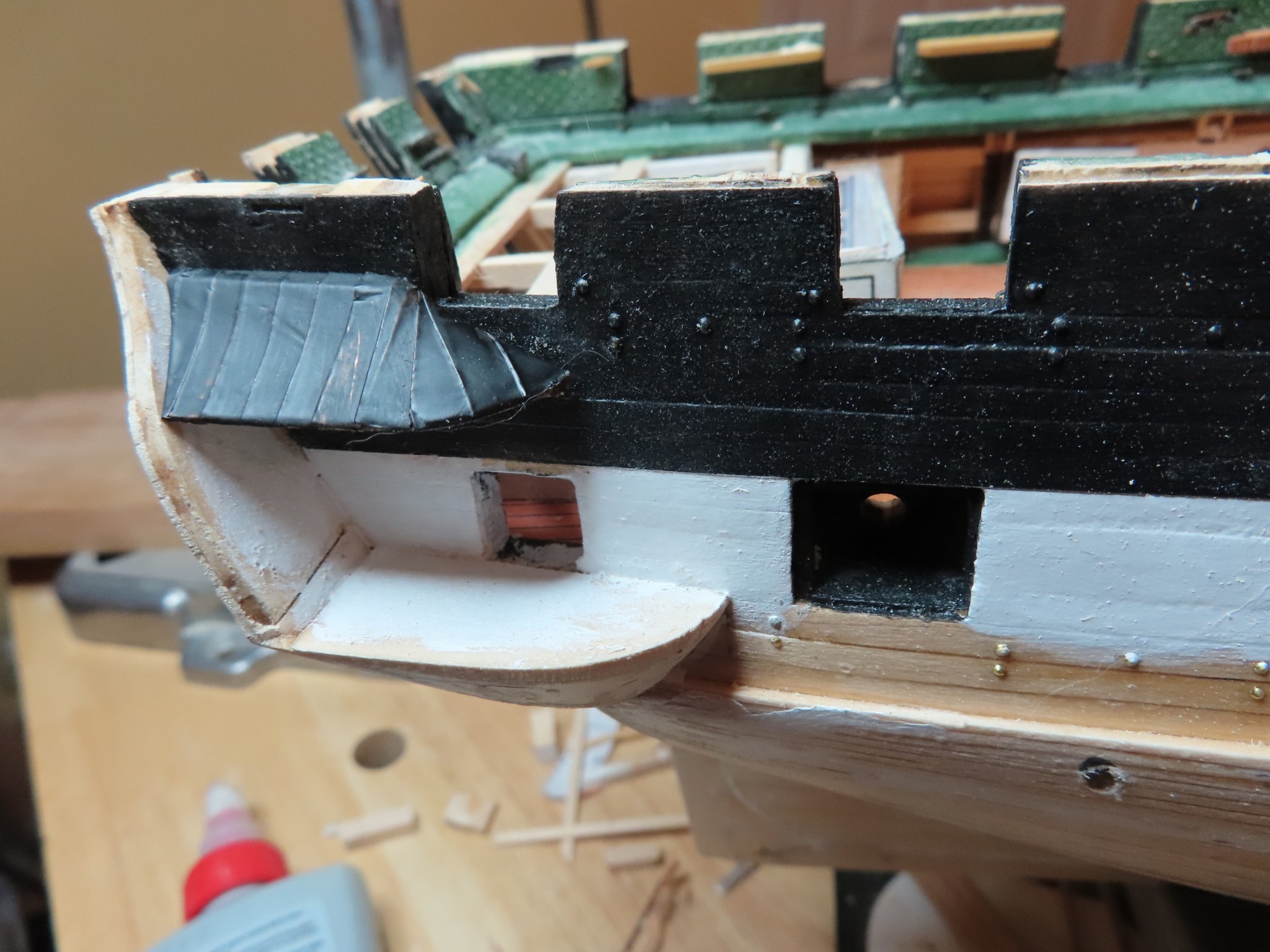
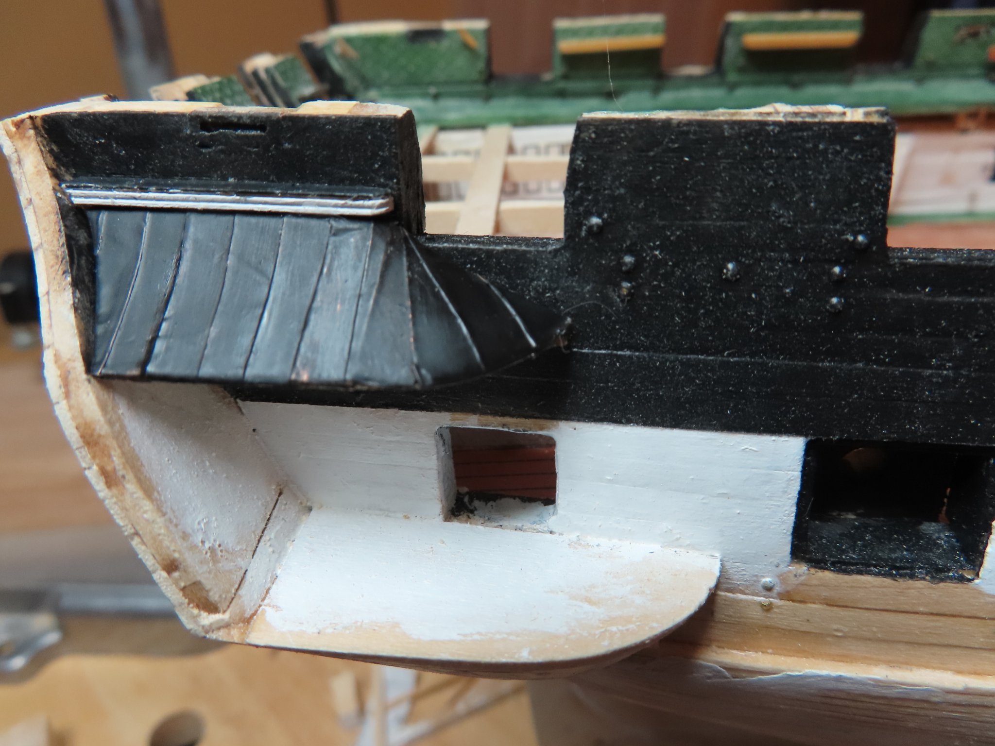
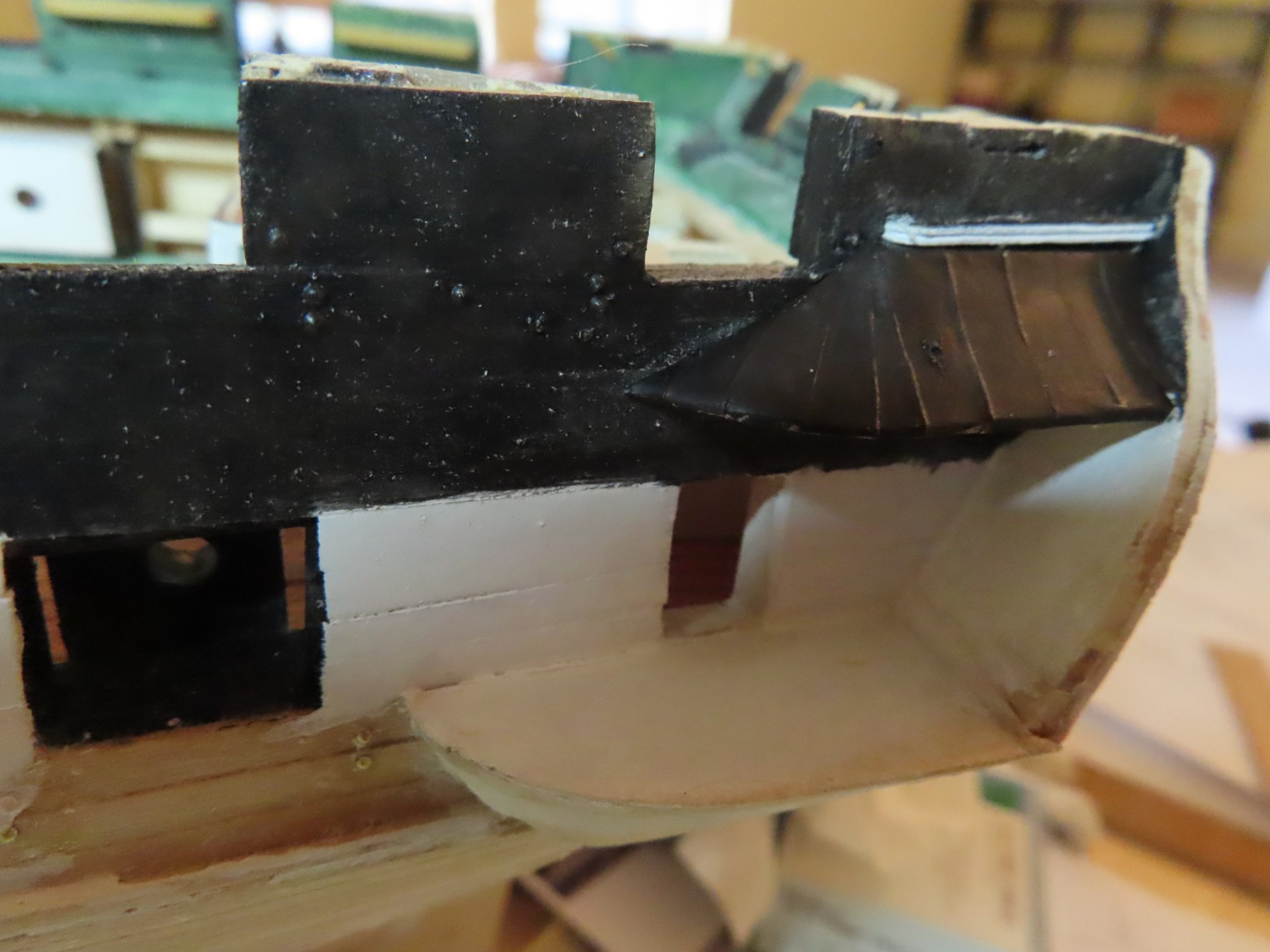
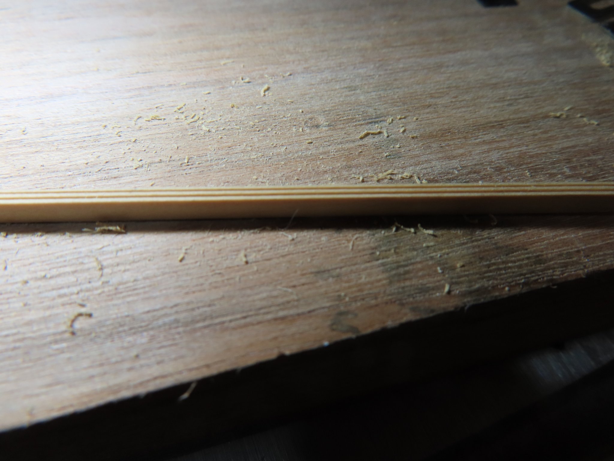
OK, here is where I go off the deep end. Most everybody who copper plates the hull (as opposed to painting) tries to provide detail for the copper nails. Some are done well, others not so much. I figure if you are going to so much trouble to simulate the dimpled surface of the copper hull, why is nobody trying to simulate the copper seams on the quarter galleries’ roof? Maybe nobody was aware there was a copper roof on top of the roof rafters and wood sheathing. You can see the roof coppering seams below.


- JeffT and GrandpaPhil
-
2
-
-
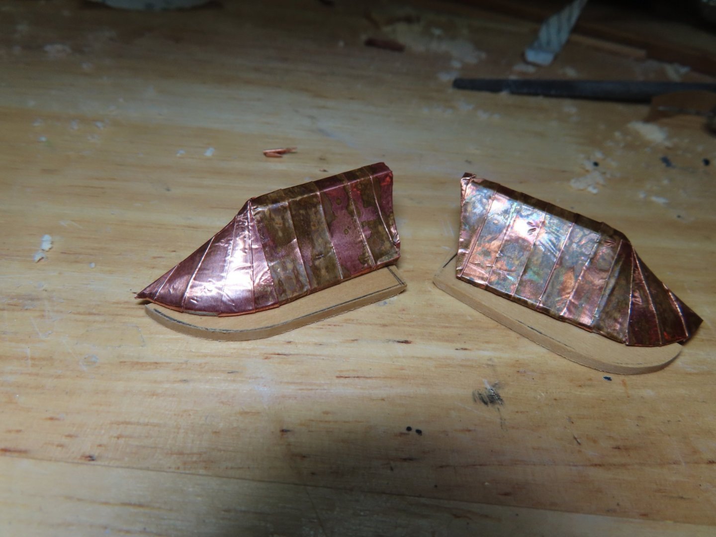
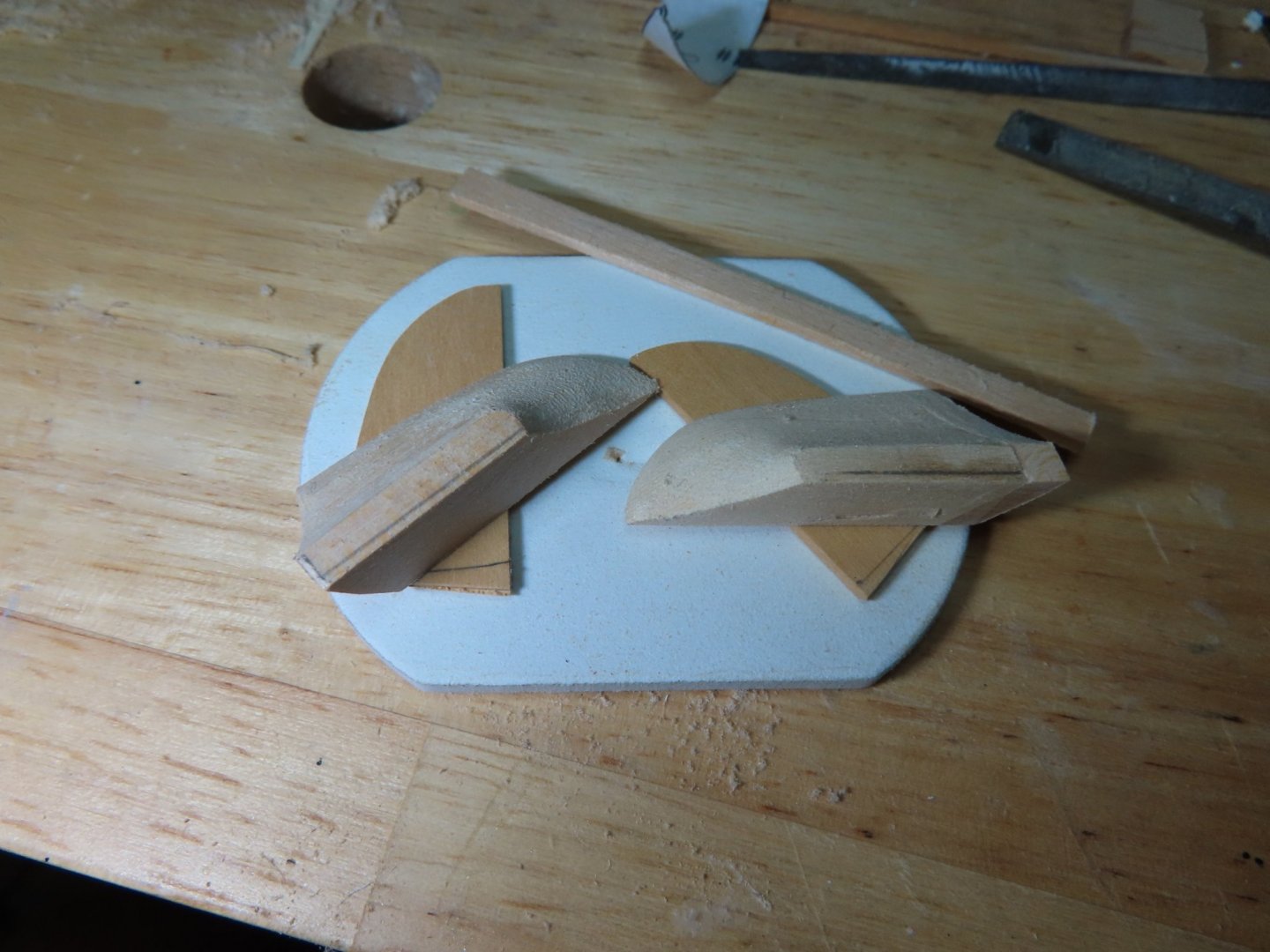
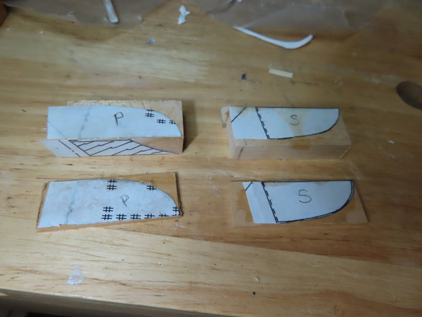
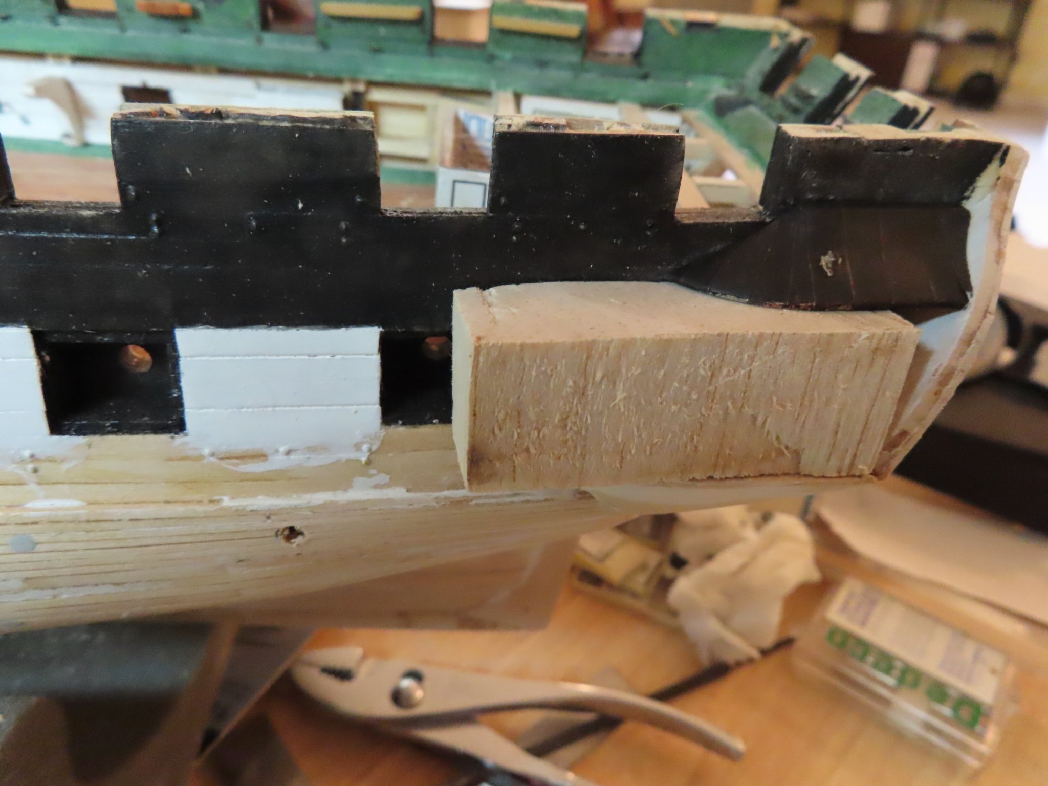
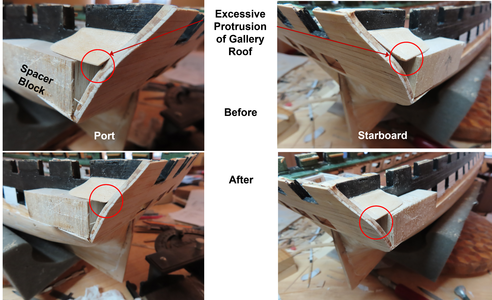
I noticed that the practicum, for what ever reason, skipped fabricating a roof element. These were the 1/16” bases of the roof blocks which sits directly on the quarter gallery cabin. Because there is fine detailing that will be added to the gallery, I am using boxwood in lieu of basswood wherever fine detailing is required. Boxwood is harder than basswood so it will hold fine edges better. Using my disc sander and a Dremel tool with a drum sander, two pieces for each gallery were cut and carved to shape. There are two long narrow 1/16” thick roof caps that I have yet to fabricate.
- Boatsinc2000, KurtH and GrandpaPhil
-
3
-
Basically, what this boils down to, is positioning the roof to the to the most aft gun deck gun port landmarks and then extending the roof dimension aft to the transom. The kit plan’s roof is just too short. In effect, this is what Mr. Hunt did. In fact he had to add additional wood to the roof block after he fabrication because it was based strictly on the kit plans. Because I now know this beforehand thanks to the practicum, I cut my roof pieces extra long so that it may eventually be trimmed to the proper size based on my model.
- GrandpaPhil and KurtH
-
2
-
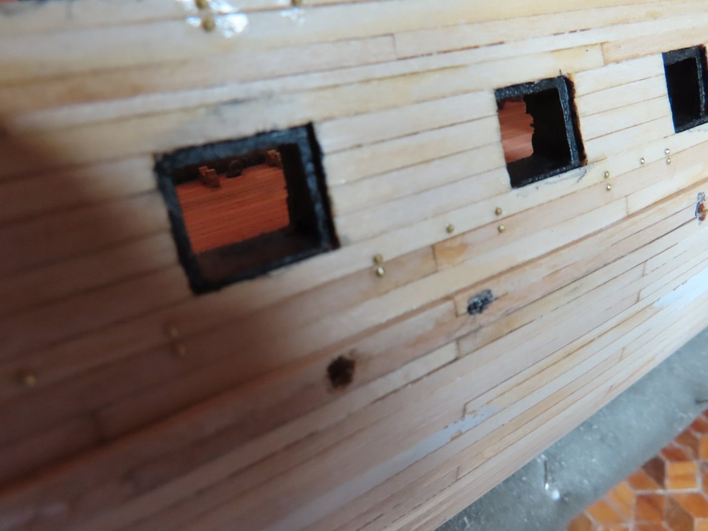
For those of you interested in whether I wasted my time applying the faux bolt heads, if the light is right and if the moon is in the Seventh House and Jupiter aligns with Mars, you can just see them if you squint your eyes and look at it sideways. So yeah, it was worth it.
Quarter Galleries
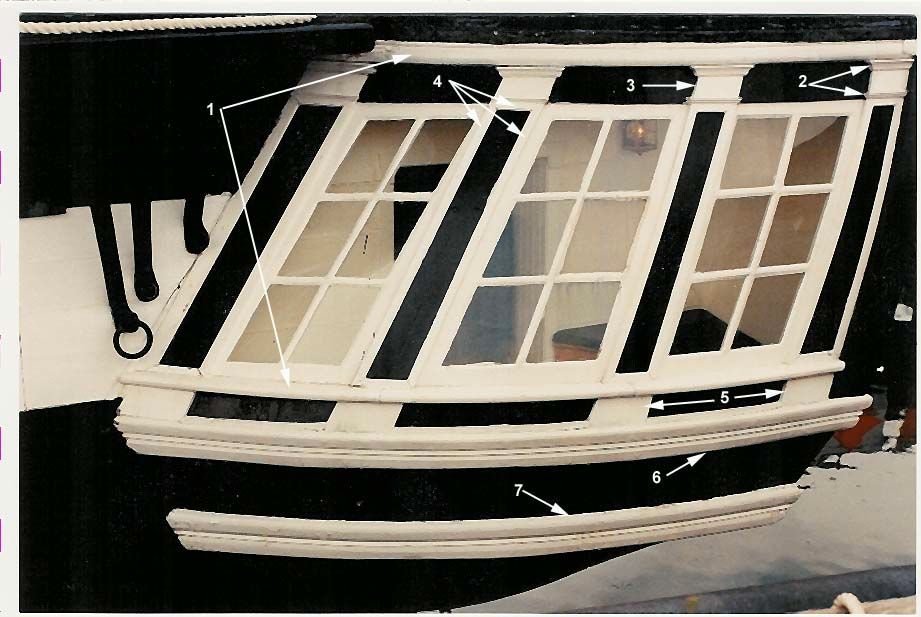
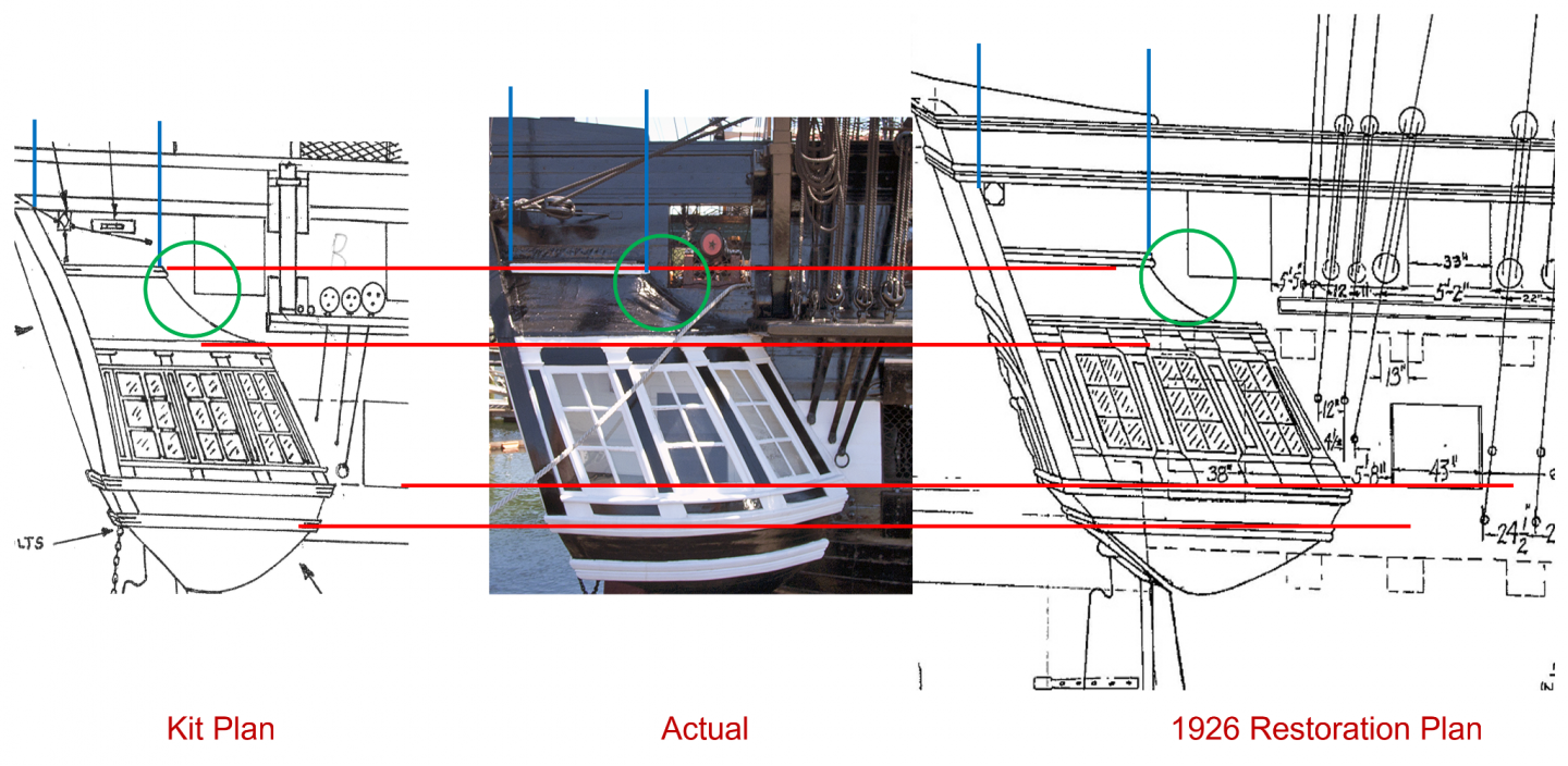
Right off the bat, the practicum identifies a problem with the galleries – the plans don’t match the actual ship. Bob Hunt was concerned when he saw that the most aft gun deck gun port, bottom aft corner almost touched the roof the gallery. However, the plans showed a larger gap. So I checked and compared the kit plan, against the 1926 restoration plan (which the kit is based on), and the best photo of the gallery I could find. The problem is compounded by the fact everything is perspective distorted either by the camera or the draftsman’s line projections. In the image below, the red lines line up the horizontal lines of the gallery. The blue vertical lines show the horizontal distortion. The kit plan shows the gallery compressed horizontally compared to the photo and 1926 plan. The green circle is Bob’s original concern with the gun port. The answer is to build so it “looks like” the plans but not necessarily exactly like the plan. And by “plan”, take your pick.
- Marcus.K. and GrandpaPhil
-
2
-
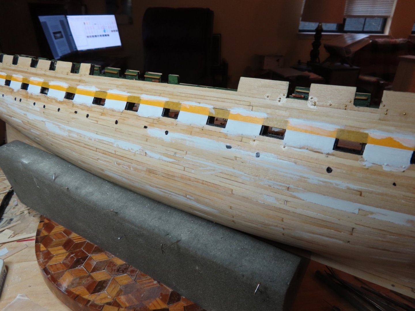
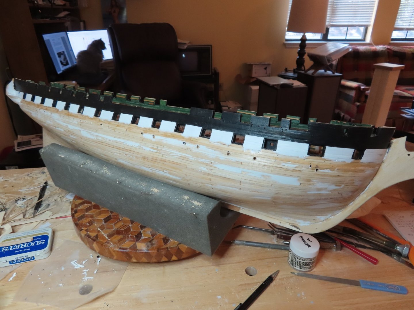
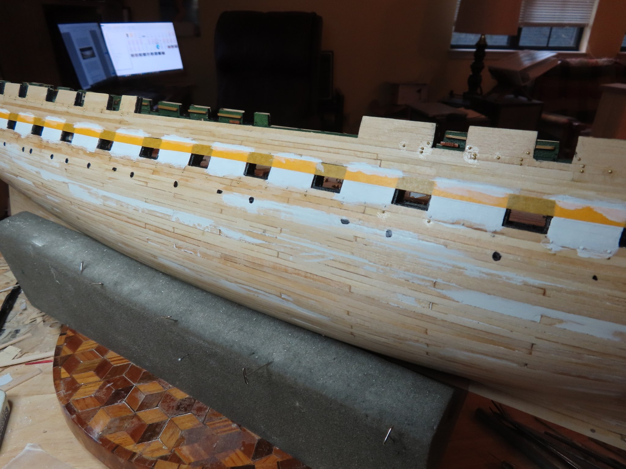
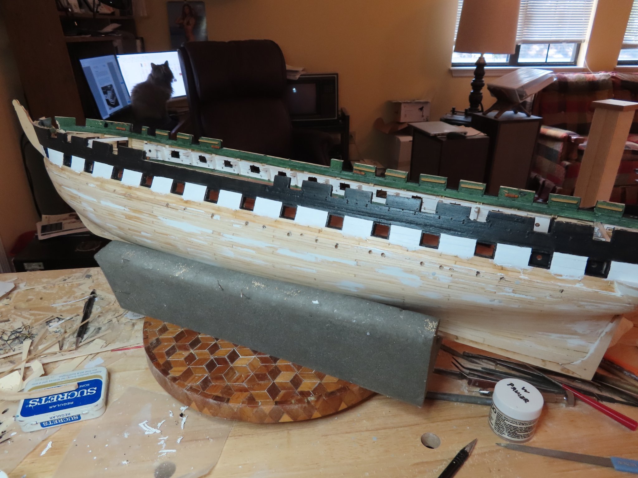
¼” wide auto pin striping tape was applied to the hull lining up exactly to the tops of the gun deck gun ports. A thin coat of white paint was applied along the top edge of the tape to seal off any potential bleed points. If there were any, it would bleed white on white. Then three coats of black paint were applied to the hull. Once the third coat dried to the touch, the tape was carefully peeled away. I have not done very much detail painting of this manner, so I had some minor touch-up work. Now for the interesting part, the quarter galleys.

-
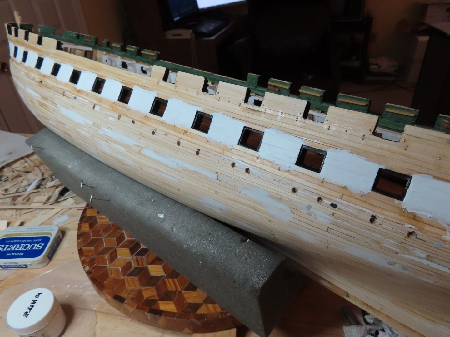
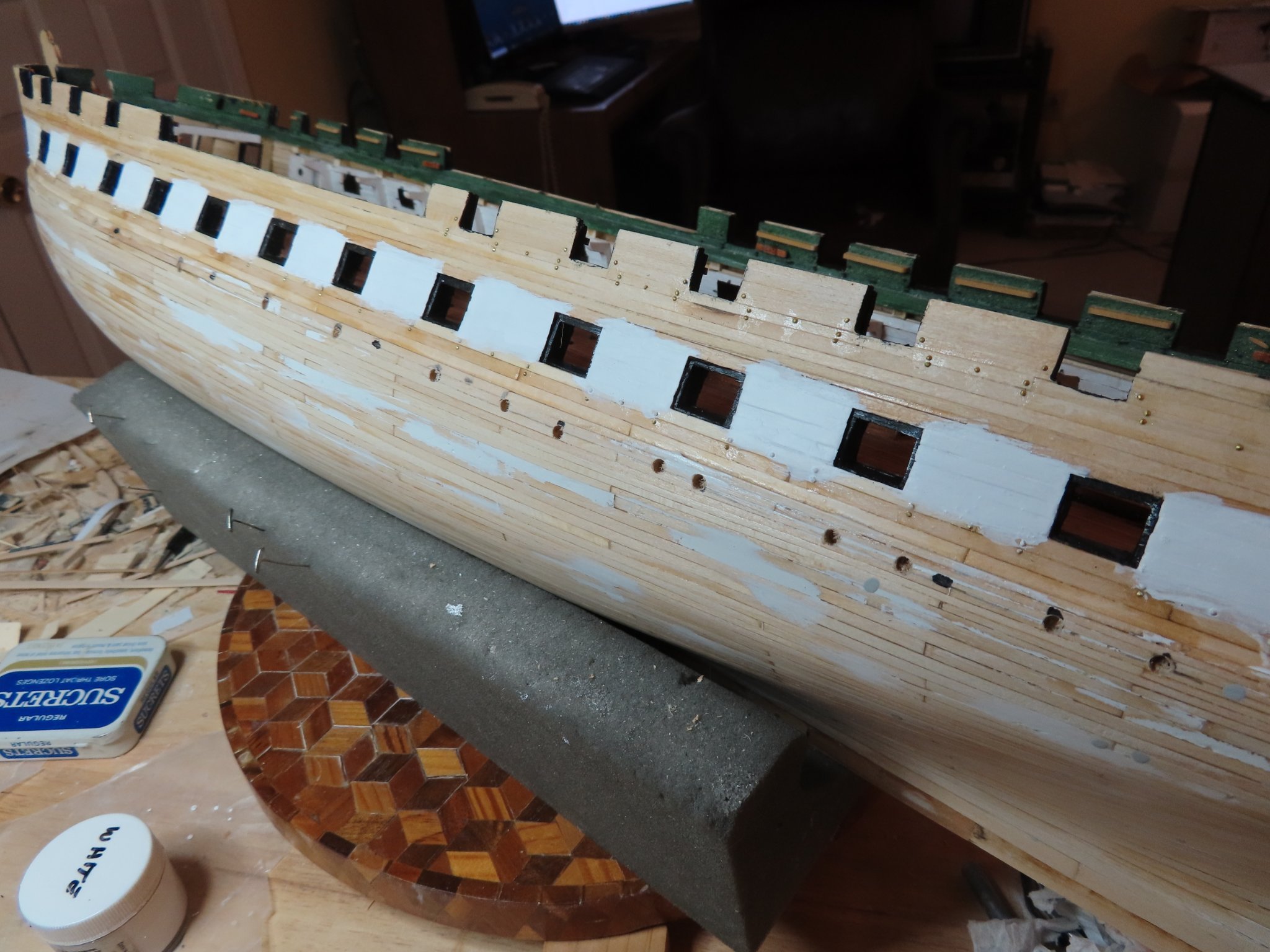
First step per the chapter is painting the interior frame walls of the gun ports black. The next step was to apply the white paint between the gun deck gun ports. I used a thin coat of white primer and then two coats of white paint, both supplied by the paint supplement package offered by Model Expo. The instructions specifically indicated to over paint the white areas between the gun deck gun ports to ensure full white paint coverage. The black paint to follow is supposed to cover the excess.
- JeffT, KurtH, GrandpaPhil and 1 other
-
4
-
Change of Plan – Painting the Upper Hull
While waiting for my drill bits to arrive, I decided to look ahead at the infamous quarter galleys that has been the bane of so many builders by reading Robert Hunt’s practicum’s Chapter 7, “Outer Hull Details.” I realized then that I was once more in sync with the practicum …for the most part. Among other things, the practicum directs the builder to install the port lights and scuppers after the quarter galleys are constructed. Once the quarter galleys are done, the hull details port lights, scuppers, the stem and transom decorations installation are next. All that work will free up any restrictions to competing the gun deck interior which has a lot of work. Based on that thought process, I’m postponing the port light and scupper installation and will proceed to following Chapter 7.
Since I have already marked the port lights and scuttle locations, I went ahead and drilled pilot holes with the new drill bits, so their locations wouldn’t be lost when this portion of the hull is painted black and covers up my position marks.
-
Very nicely done. I know the Byrne's saw is a thing of beauty, but didn't know it could cut those small pieces with such s large toothed blade. Anything that delicate, I always switch to my finest tooth blade. Maybe it's because you got the sliding table attachment? I don't have that one.
Jon
-
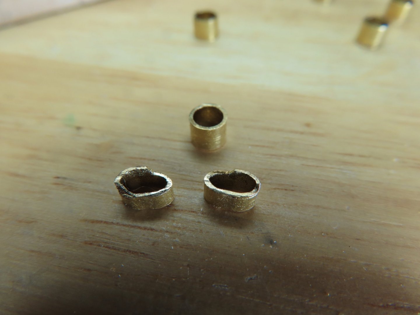
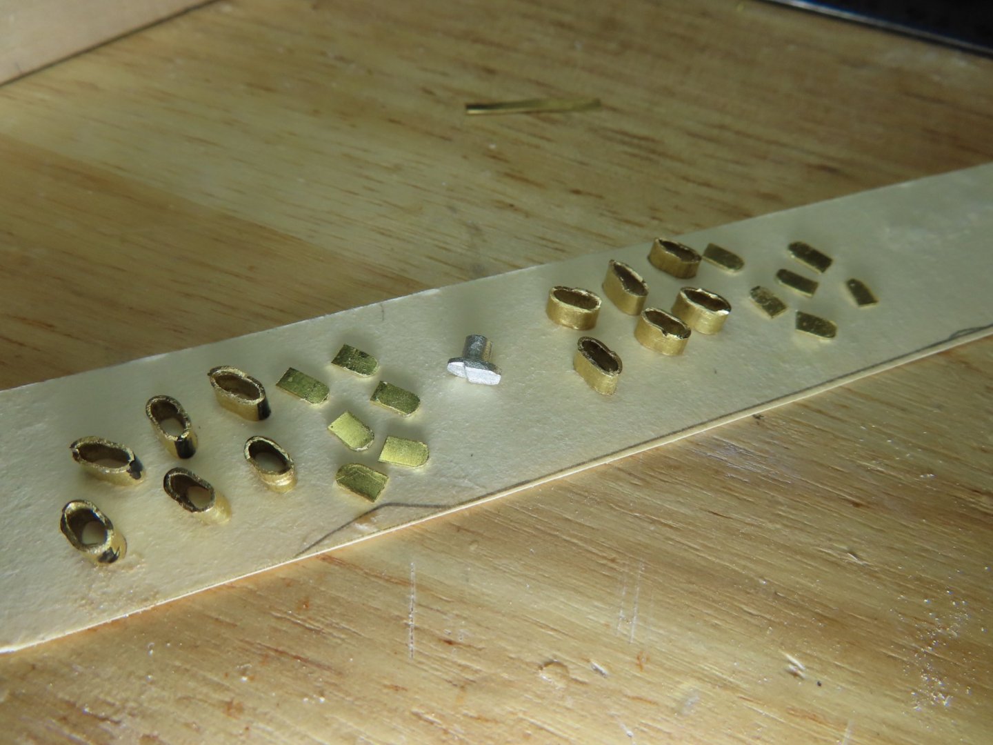
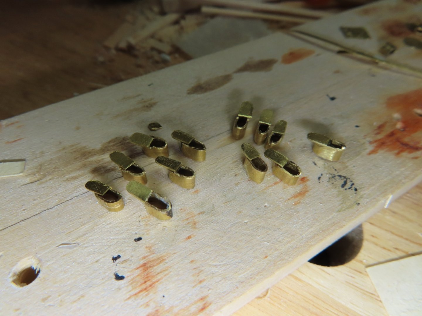
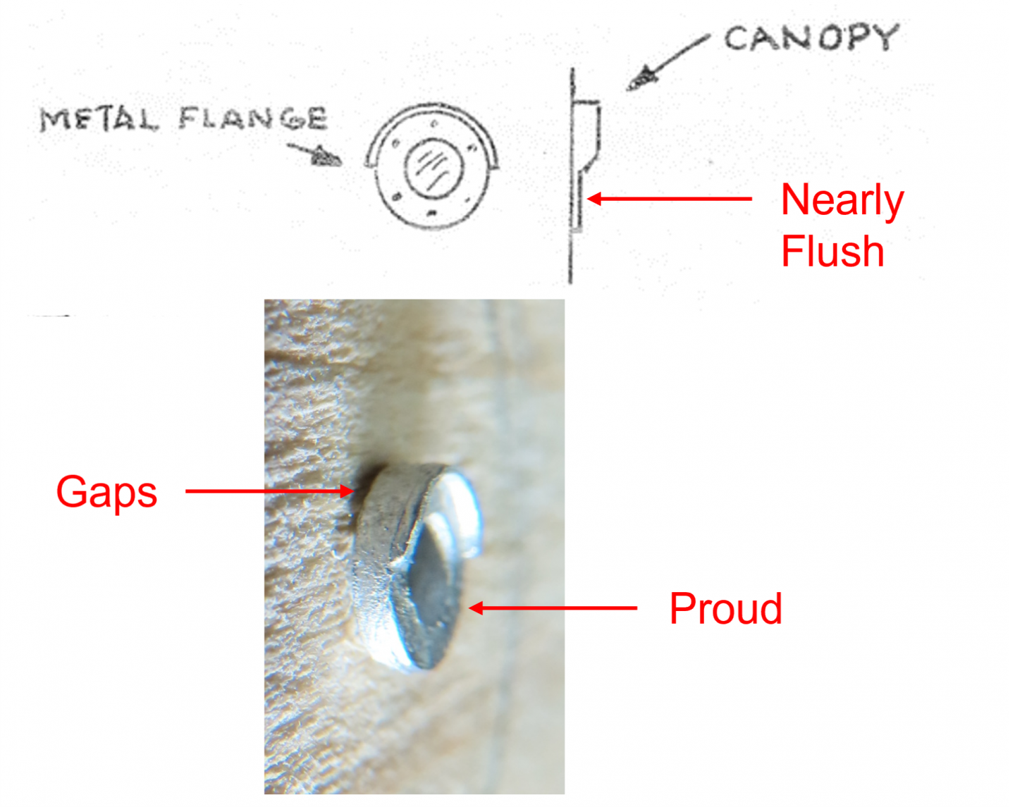
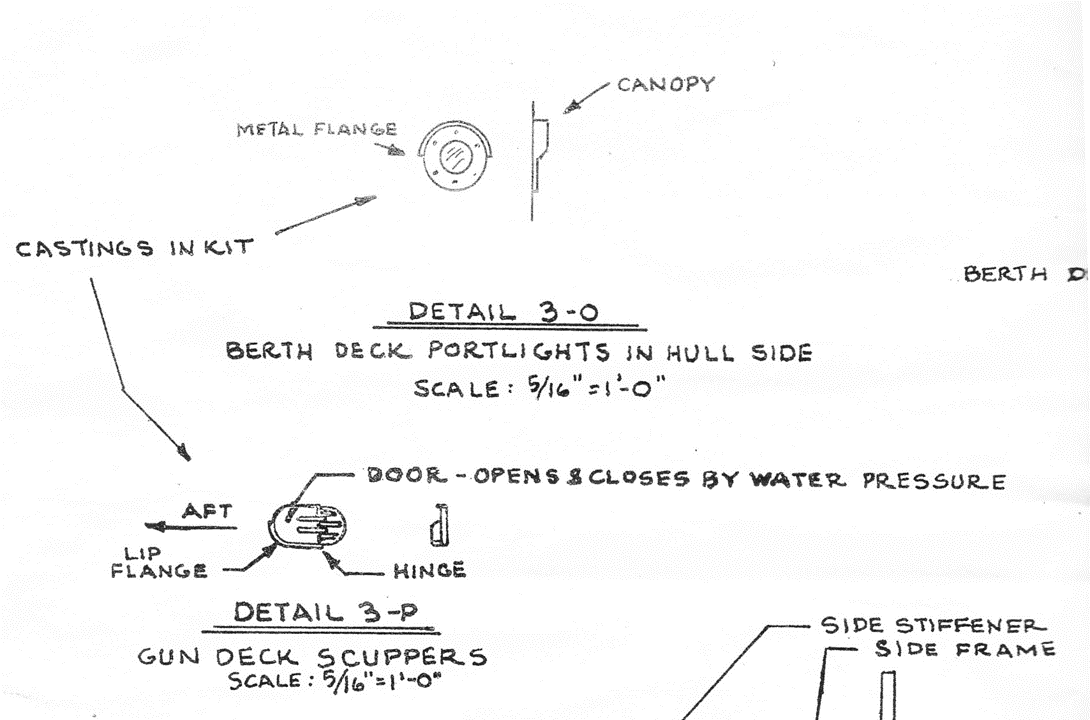
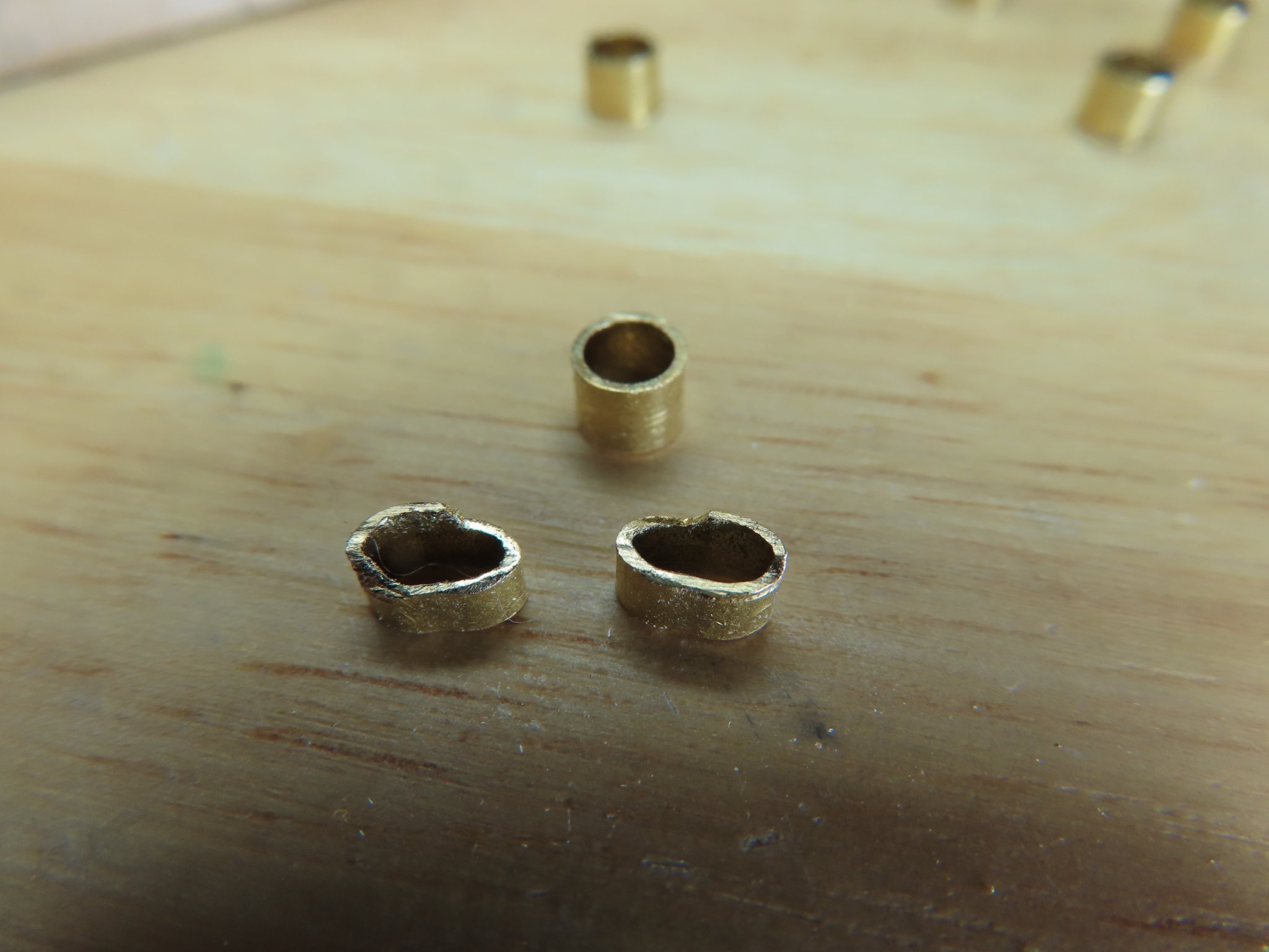
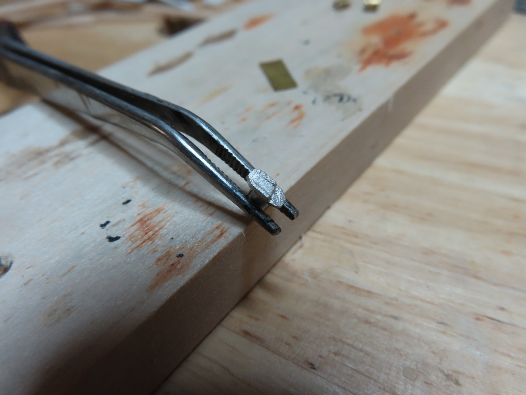
Using a 5/32” dia. brass tube (chosen by trial and error), short pieces are cut off and squeezed just enough to create an 0.0960” oblong cross section tube. A piece 0.010” sheet brass, was cut into a rectangle with one end rounded to represent the scuttle door. Filing the edge of the formed tube leaving the corner edge proud creates the lip flange. In order to drill a couple of holes to create the oblong shape, requires a 7/64” ( 0.1094”) bit. Another drill bit I needed (I actual purchased a set of 16 bits) The door was attached with CA glue. These will be inserted into the wide hole in the hull almost flush leaving the door and flange lip protruding from the hull. This will provide some detail even when painted black.
-
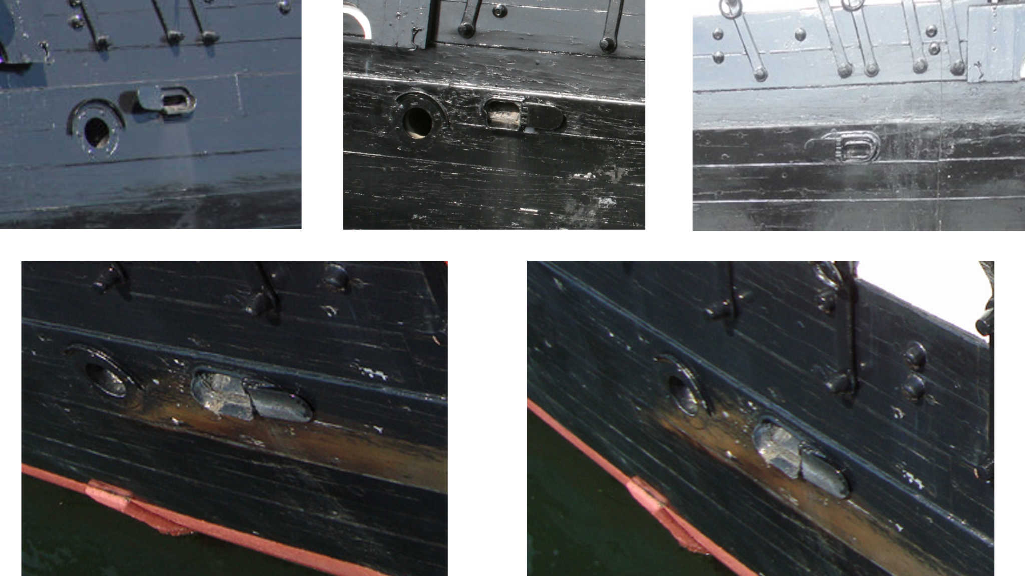
In short, on the actual ship, the scuppers are wide open whereas the kit plan and castings have them closed. At first, I thought the casting were misshapen due to their small size and I would have to make them from scratch. The kit plan states the scuppers are opened and closed by water pressure, so I suspect on the real ship, they are being held open somehow for some reason. This explains the casting’s appearance.
Looking at the casting more closely, you may notice that there are two crude lip flanges. The actual lip is always on the bottom aft end of the scupper. By filing off one of them, the casting can be properly installed on the appropriate side of the ship. But this really moot because if I were to install them as is and eventually paint them black like the hull, you might as well as not install them at all; you can’t see anything to identify them as a scupper. So being a glutton for punishment, I decided to make them from scratch and show them open.

- Boatsinc2000, Marcus.K. and ERS Rich
-
3
-
However, it was a different story with the scuppers.


- Marcus.K., Boatsinc2000 and ERS Rich
-
3
-
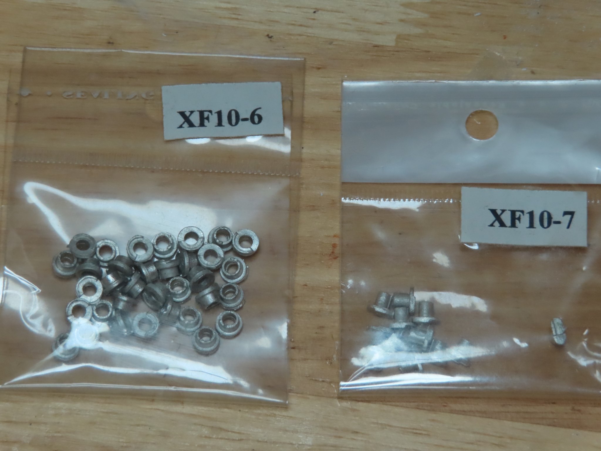
Looking at the portlight castings, they looked straight forward enough, although based on the photographs and the kit plans, they have to be set almost flush to the hull and not proud if inserted into the hull using the just casting tenon. Additionally, when I made a test installation in a block of scrap wood, the casting also tended to leave a gap between the casting and the hull. That meant drilling into the hull twice, once for the casting tenon and a much shallower larger diameter countersink for the outer diameter of the port light to set into.
By my measurements, the tenon is about 0.1385” dia. it varies a bit on the casting, (a little larger than a 1/8” (0.1250”) drill bit and little less than a 9/64” (0.1406”) bit. The full diameter of the port light is 0.1825”, just shy of a 3/16” (0.1875”) bit. Ideally, I would use the 9/64” and 3/16” bits to drill the holes, but I could not locally buy a 9/64” bit and had to order online. The order is due in a week. In the meantime, I cleaned off the tiny imperfections from the casting process.
- ERS Rich and Boatsinc2000
-
2
-
Berth Deck Portlights and Scuppers
Next, I thought I would install the berth deck portlights and scuppers castings; something nice and simple…Ha!.
- Marcus.K., KurtH and Boatsinc2000
-
3
-
I was surprised to see you paint over all of the cleats and other hardware. Did you want them green?
-
Jeff, I haven’t reached the point where the I’m installing things like the trim and decorations yet. If you’ve been following my build log, you may have observed that I like the little details. So, I haven’t read or planned for those yet, but I noticed the very nice eagle on the stern of your model. How did you apply the colors to the eagle’s shield? Does the practicum provide the process? If I were to do it today without any outside instruction, my first attempt would be to make a decal using my inkjet printer. I can’t tell from the photographs, but did you make the stern stars or were they provided in the kit? I should know what’s in the kit, but I concentrate on one thing at a time and constantly have to refresh myself when I move on to a new task.
The coppering concerns you raised is something I must contend with as well, obviously. I’ve been thinking about this for a long time. I looked at models built before the last restoration and noticed a majority of them did the copper nailing wrong, They made the coppering look like boiler plate rivets with oversized “rivet” bumps proud of the copper surface. Looking at the images of the restoration, it was obvious there should be fine dimples into the surface of the copper, which I may add is a long and tedious process. Some builders used a fine ponce wheel on the plate edges only, others a pressure stamp with multiple needle points for the whole plate. I plan on doing a few trial processes to figure out what I’ll do. One thing is clear to me though, there will be copper plates and not just copper paint on the hull.
Jon


USS Constitution by JSGerson - Model Shipways Kit No. MS2040
in - Kit build logs for subjects built from 1751 - 1800
Posted
Constructing the bench seat was straight forward. Using the Starboard image with the privy revealed, I eyeballed the shape and height of the bench. The base was scored to give the impression of vertical boards. Also, the image revealed that the floor had to be repainted as I had initially painted interior completely white. This meant scraping the white paint off with an X-acto blade and staining the wood. By the time the windows are installed, I doubt any fine details will be visible, but the viewer will know something is in there. Again, my philosophy, the closer you look, the more you see. It keeps the viewer engaged.