


JSGerson
-
Posts
2,168 -
Joined
-
Last visited
Content Type
Profiles
Forums
Gallery
Events
Posts posted by JSGerson
-
-
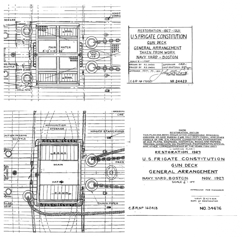
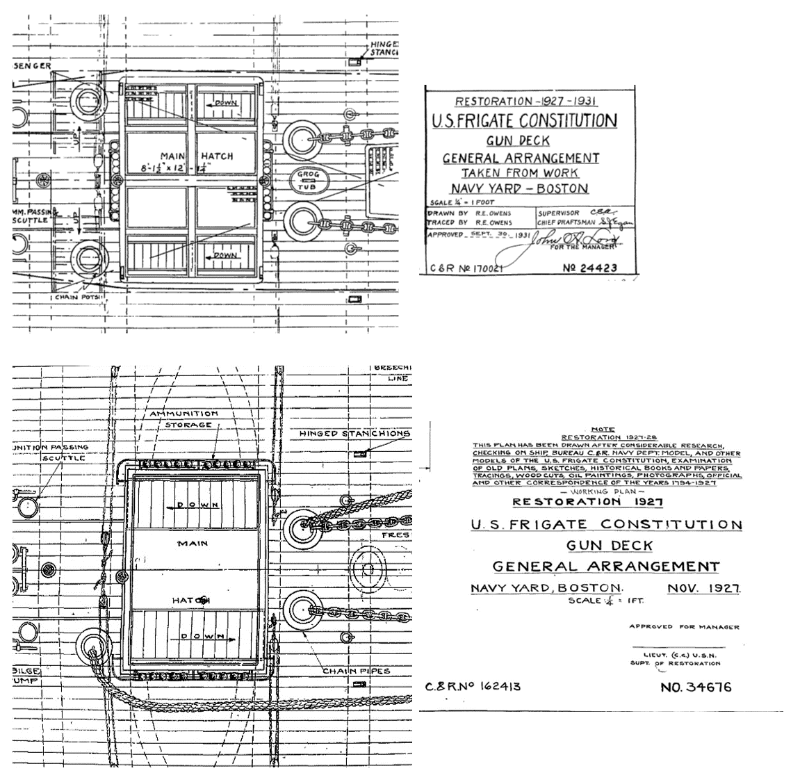
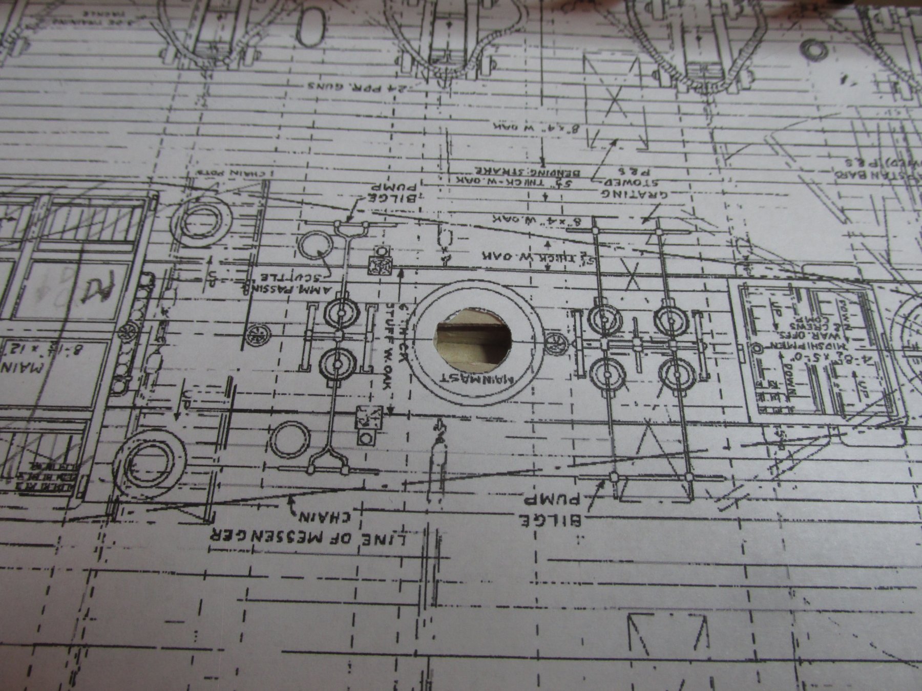
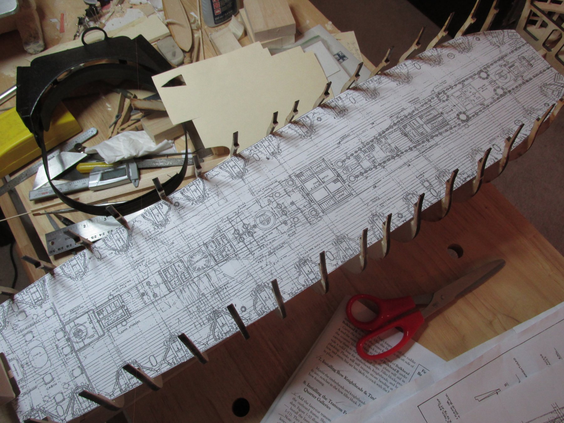
Those openings which will be covered with a grating, do not need to be cut. So, the only places which do require cutting a hole, are where the ladders pass through the hatches to the berthing deck. That should be easy too, I have the US Navy plans to show me where to cut…But not so fast. I have two detailed arrangement plans for the gun deck, one dated September 30, 1931 and the other November 1927. For the gun deck main hatch, they don’t match. To make matters more interesting, neither of them match what is existing today. My original assumption was that the 1927 version was the “before” and the 1931 was “after” the restoration. But somewhere along the line, there is what actual exists, so the plan is to build the reality.
- Geoff Matson, Nirvana, CaptainSteve and 5 others
-
 8
8
-
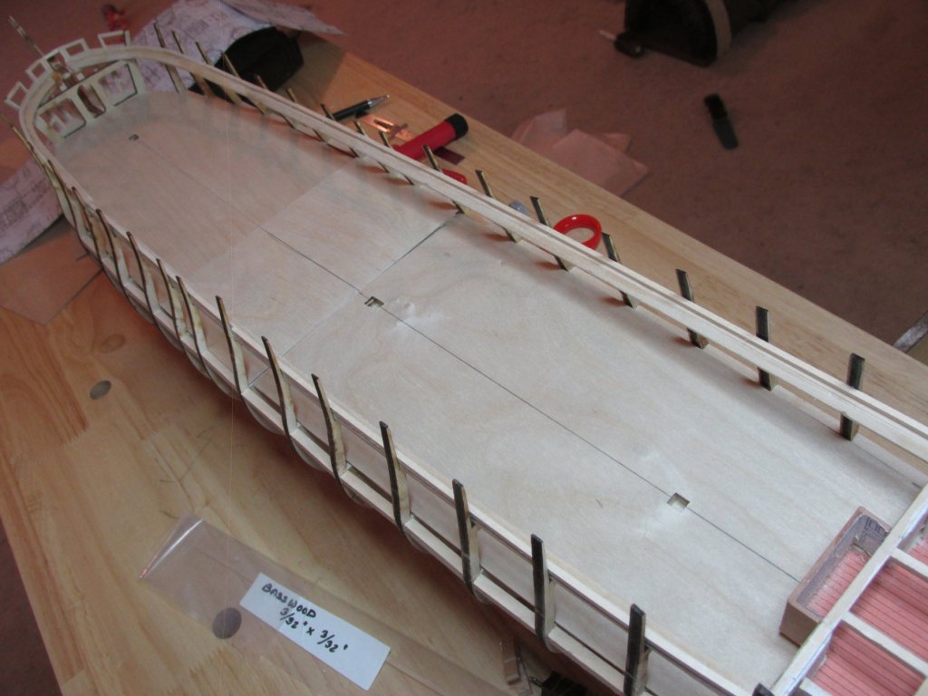
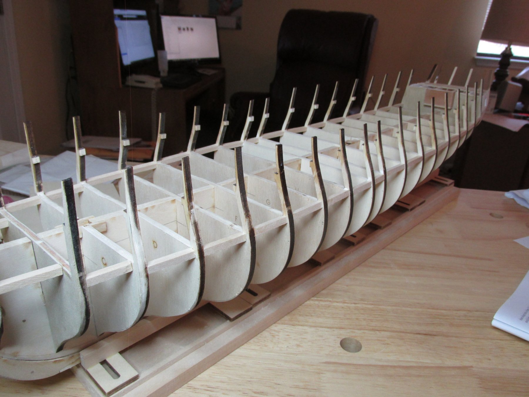
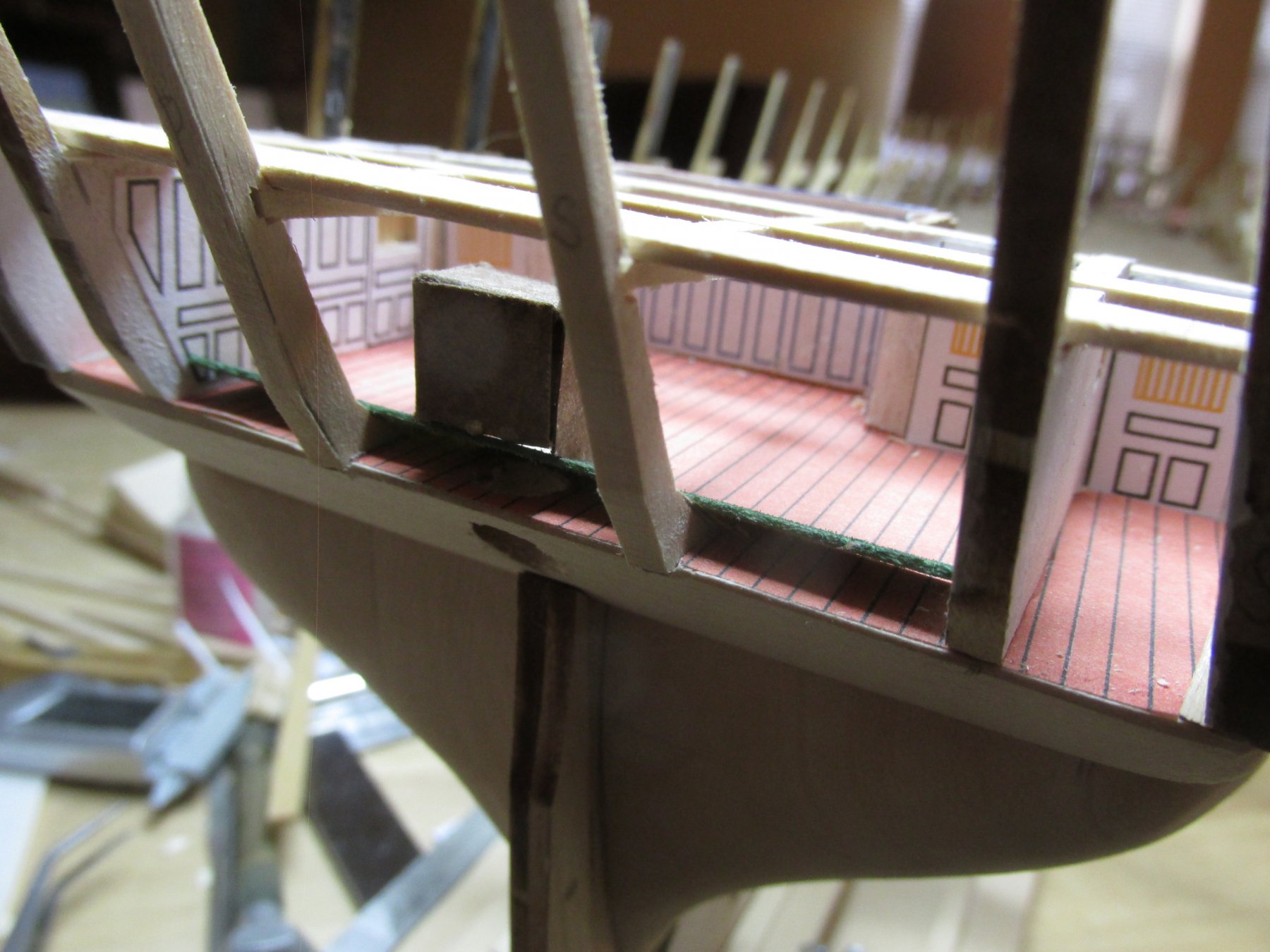
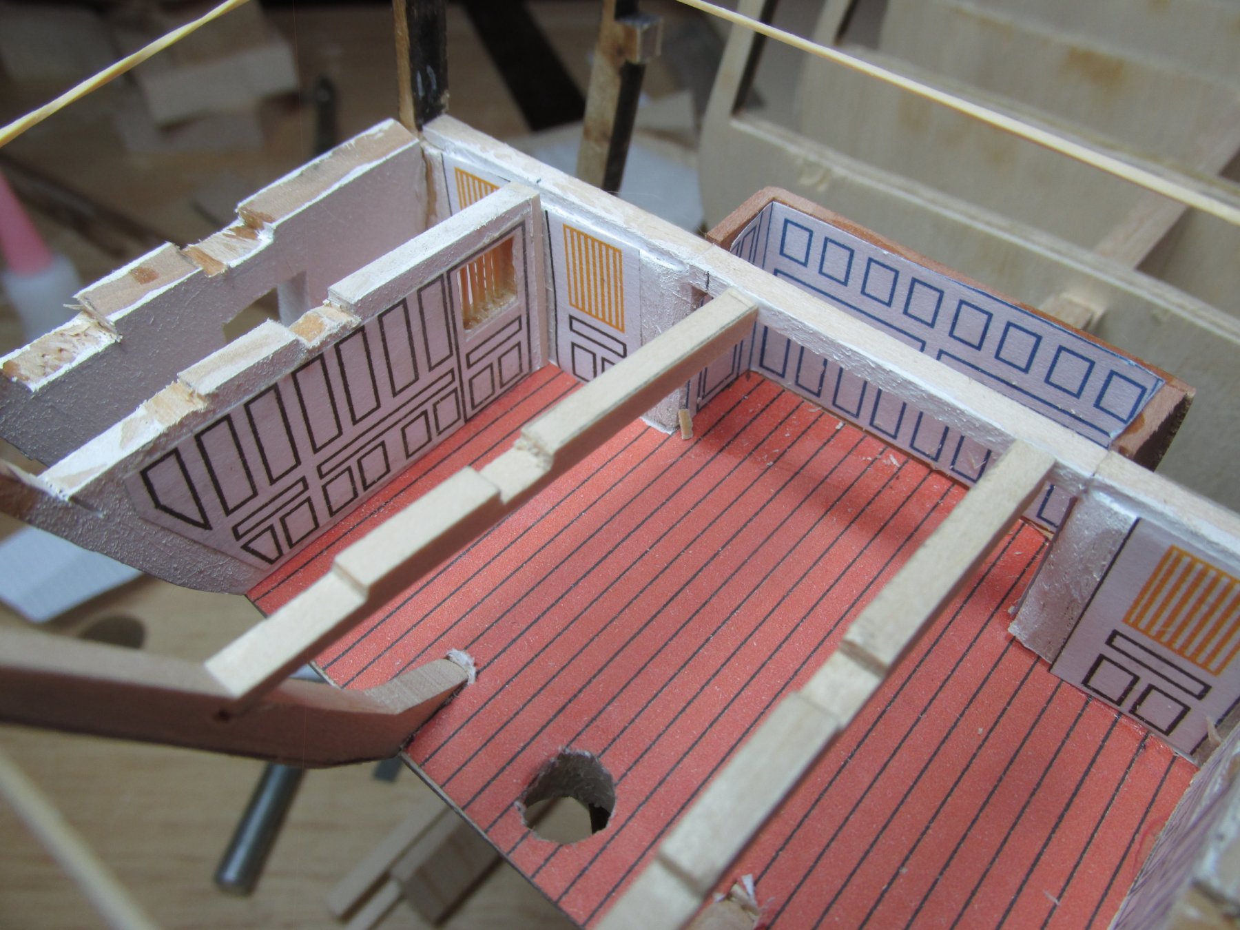
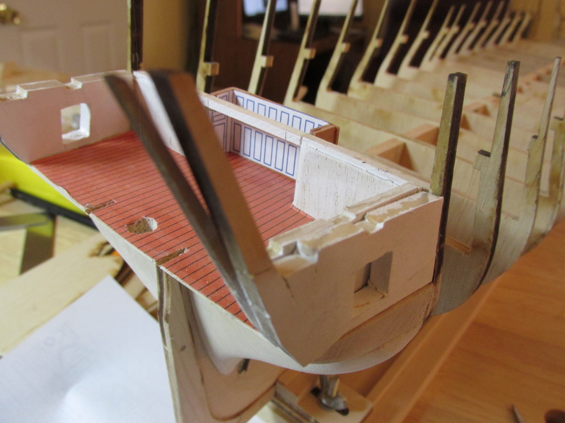
Gun Deck Waterway – Plywood Foundation
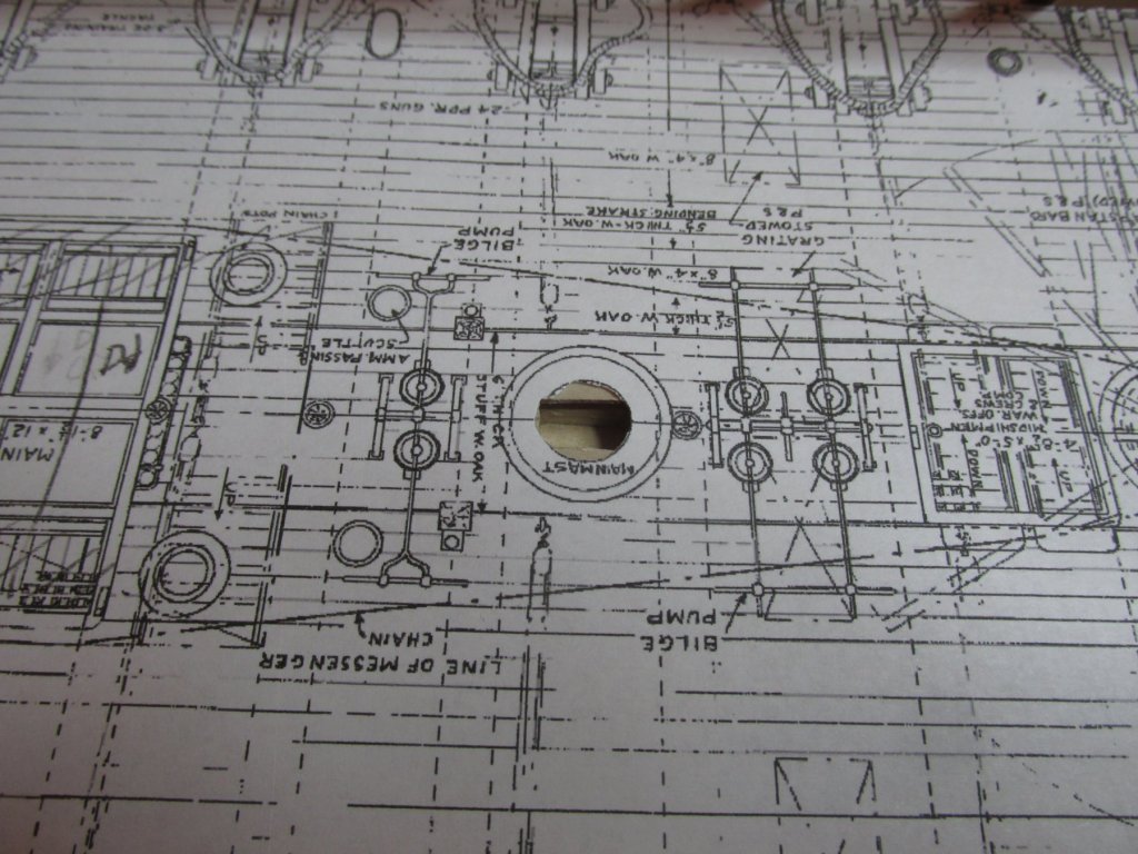
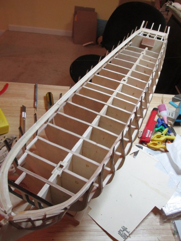
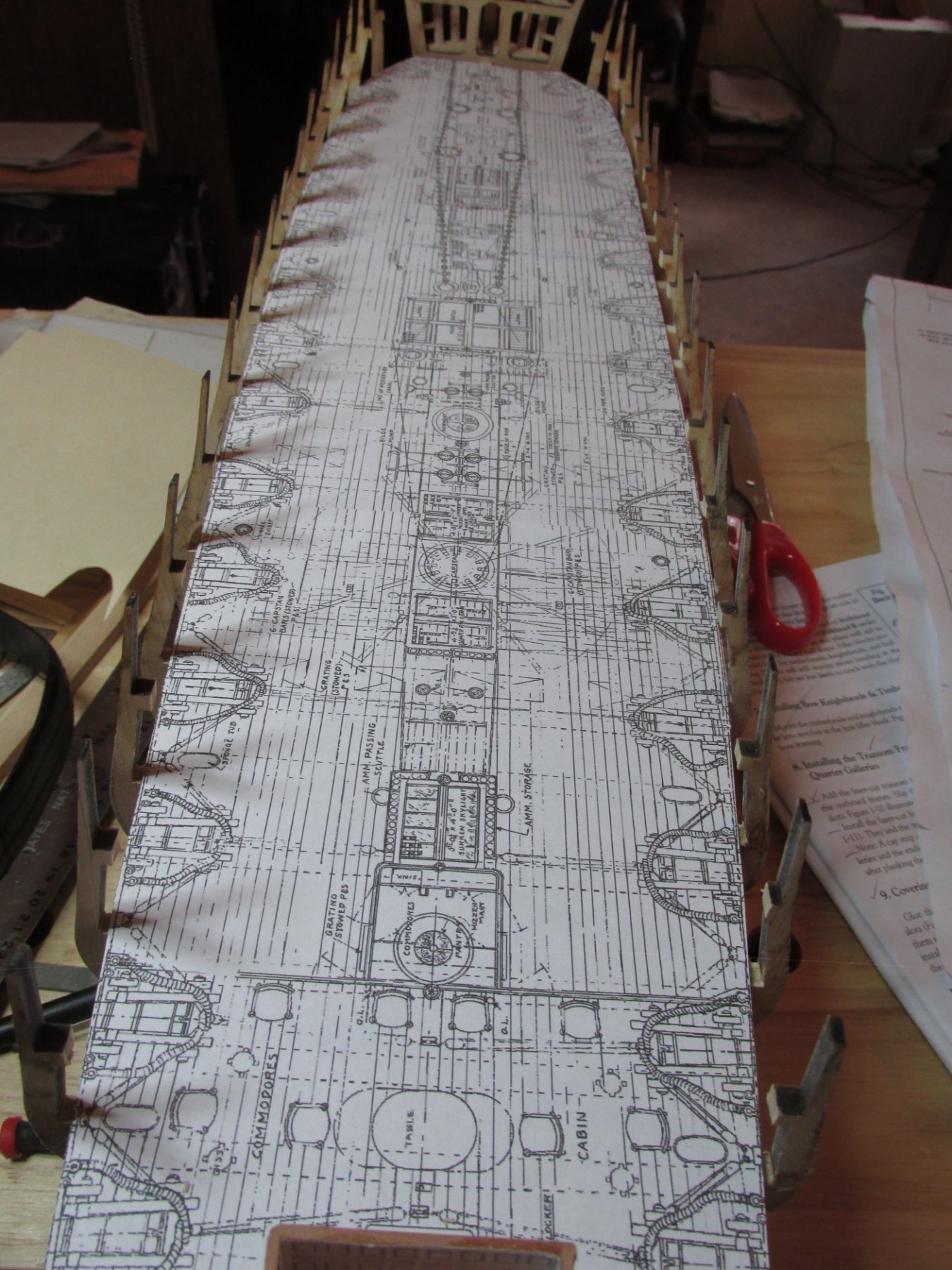
There are several different paths I could have chosen pertaining to what to do next. Some builders installed their framing for the gun ports, others worked on the transom. Since I just installed the waterway on the spar deck, I decided to install the waterway on the gun. To do that, I purchased a large sheet of 1/32” plywood and using the US Navy plans for the gun deck as a template, three pieces were formed to fit onto the bulkheads. This has a twofold effect; it provides a solid smooth support for the gundeck planking and it smooths out any imperfections in bulkhead heights and shapes of the deck when I modified the bulkheads and keel. Once the plywood is installed, the waterway will sit on top and against the bulkhead frames just like the spar deck. I decided that since the interior of the gundeck bow from bulkhead A forward would be unviewable, that portion would not be detailed.
Before I can secure the plywood to the bulkheads and keel, now would be the time to cut the holes for the masts and any openings that may be seen through the open planks I plan to leave on the spar deck. The masts were simple enough, I drew the center line on the 3 plywood deck pieces and measured where the mast opening had to go and cut them out with an X-acto knife. That worked just fine. As noted, the plywood is not glued down in the photos below.
- Tigersteve, CaptainSteve, DocBlake and 5 others
-
8
-
Phenomenal job! Thinking ahead to when I get to this stage, or in your case looking back in hindsight, would it have been easier to make the triangle panels from a single piece of wood with openings cut into them rather than assembling 4 tiny pieces with extremely tight tolerances? Or would the solid piece just fall apart due to the nature of the material at that scale? As you found out, just the slightest deviation causes alignment issues. For such a small item, there are an awful lot of components. Out of curiosity, what type of wood did you use? I can't imagine you used basswood for this.
Jon
- CaptainSteve, Canute, mtaylor and 1 other
-
4
-
More digging: Per Fisherman Outfitter
QuoteIn the 1800s, the influence of organizations like Britain’s Royal National Lifeboat Institution (which used the kisbee ring) helped popularize life preservers. Shortly after the invention of the kisbee ring in the UK, the US Congress passed a law requiring ships to carry life preservers and similar rules have been in place ever since for military, commercial, and pleasure boats
How accurate / authentic the information is, I don't know. The choice is yours.
Jon
-
Thanks for the feed back.
I got curious about the life preserver and found this at Nauticapedia:
QuoteThe kisbee ring, sometimes ‘kisbie’ or ‘kisby’, is named for Thomas Kisbee, the inventor. He was also responsible for the invention of the ‘breeches buoy’. Kisbee was born in 1792 at Farcet, Huntingdon, England. He served as First Lieutenant(RN) in HMS Driver, the first steam paddle sloop to circumnavigate the world. He departed in March 1842 travelling via South Africa and China to New Zealand finally returning to Portsmouth (via Rio de Janeiro) in May 1847. Kisbee had spent 1846-47 transporting Governor Grey around the North Island of New Zealand during the Maori Uprising. Kisbee died in 1877 at Great Yarmouth, Norfolk, England.
Widespread use of the life preservers became the norm when organizations such as Britain’s Royal National Lifeboat Institution (1855) started using them. The institution was also using a cork life belt invented by Commander J.R. Ward USN in 1854. The RNLI set up a Board of Supervising Inspectors that set standards and rules for lifesaving apparatus.
So yes, the Constitution could of had a life ring (kisbie), but not until 1855 or later.
Jon
- Piet, SawdustDave, mtaylor and 2 others
-
5
-
Very nice recovery on the bowsprit steps. I have to admit, I'm very leary about making ladders and stairs. Consistency in the steps geometry is paramount. How did you make them? I checked back in your log to when you first made them and you didn't address your method. Were they hand cut? If so, that is some precise cutting; or did you use a milling machine? I have a long way to go before I get to that stage, but I'm already apprehensive.
Jon
- SawdustDave, CaptainSteve, mtaylor and 1 other
-
4
-
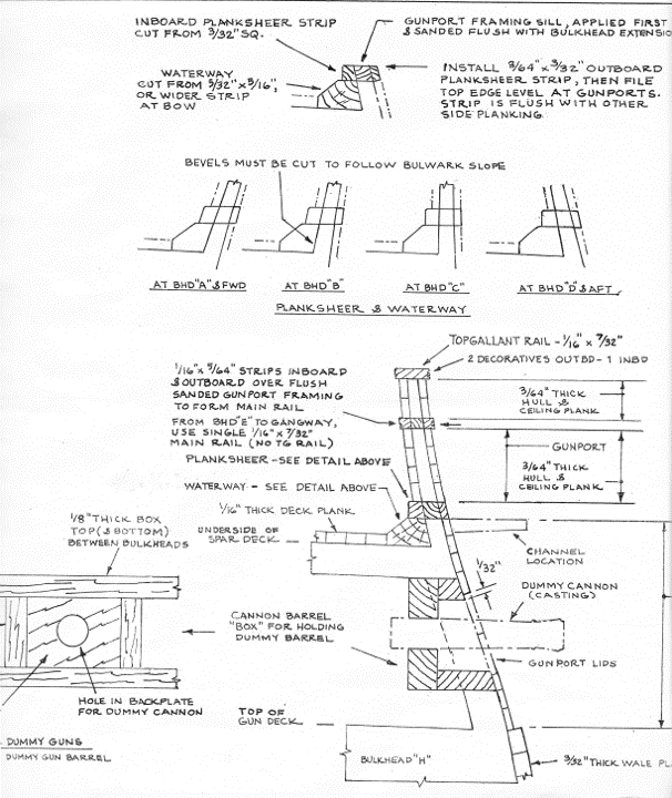
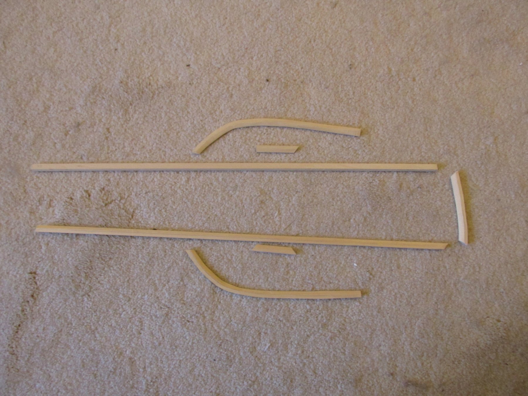
You may have noticed that when I originally cut the bulkheads to allow the formation of the gundeck, I left a remnant of the spar deck on the bulkhead. The waterway was fitted against the bulkheads and glued to these short outcroppings. Then the planksheer, made from 1/16” x 1/16” basswood stock, was fitted and glued on top of waterway, also flush against the bulkheads.
-
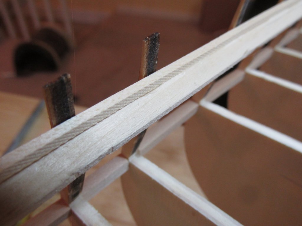
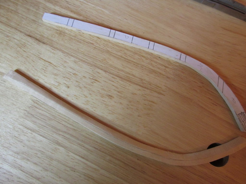
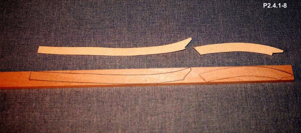
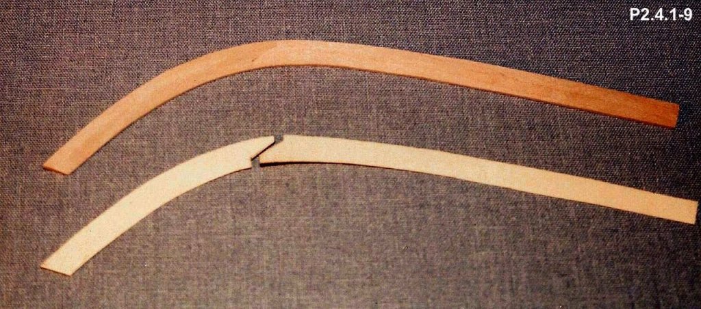
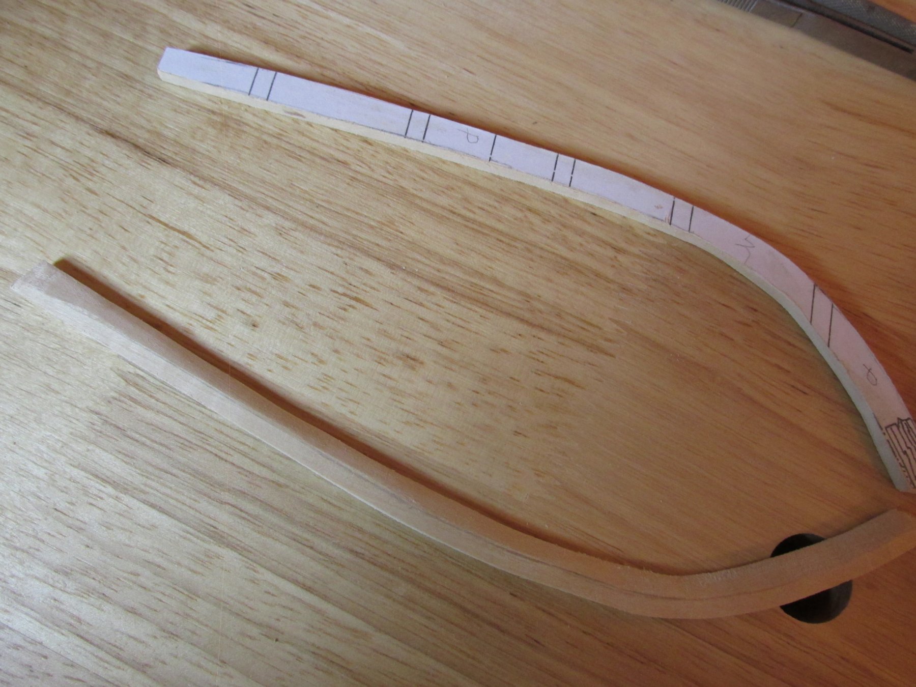
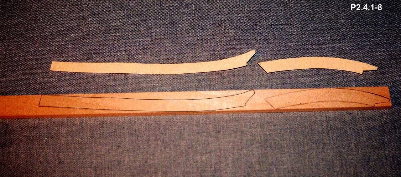
I found that I could not fit the curve onto my piece of ½” wide wood. Instead I opted to buy a 3” x 3/16” piece of basswood from my local hobby store. This enabled me to make a one-piece pattern directly from the kit plans. Note that in either case, the stock wood was 1/32” too thick and had to be sanded down.
As mentioned in the post “The Next Step”, the waterway has a trapezoidal cross-section that changes as it moves away from the bow and stern. Mr. Hunt made his bevels using an X-acto knife. I’m not that good that I could make consistent cuts over the length of the model. I chose instead to use my $10 mini razor plane I got a Micro-Mark some years ago. The curved section was however had to be formed with the X-acto knife, files, and sanding sticks.

- DocBlake, CaptainSteve, Nirvana and 1 other
-
4
-
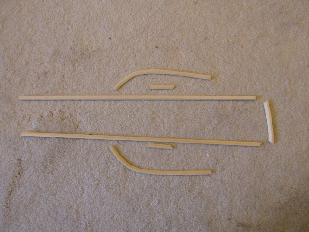
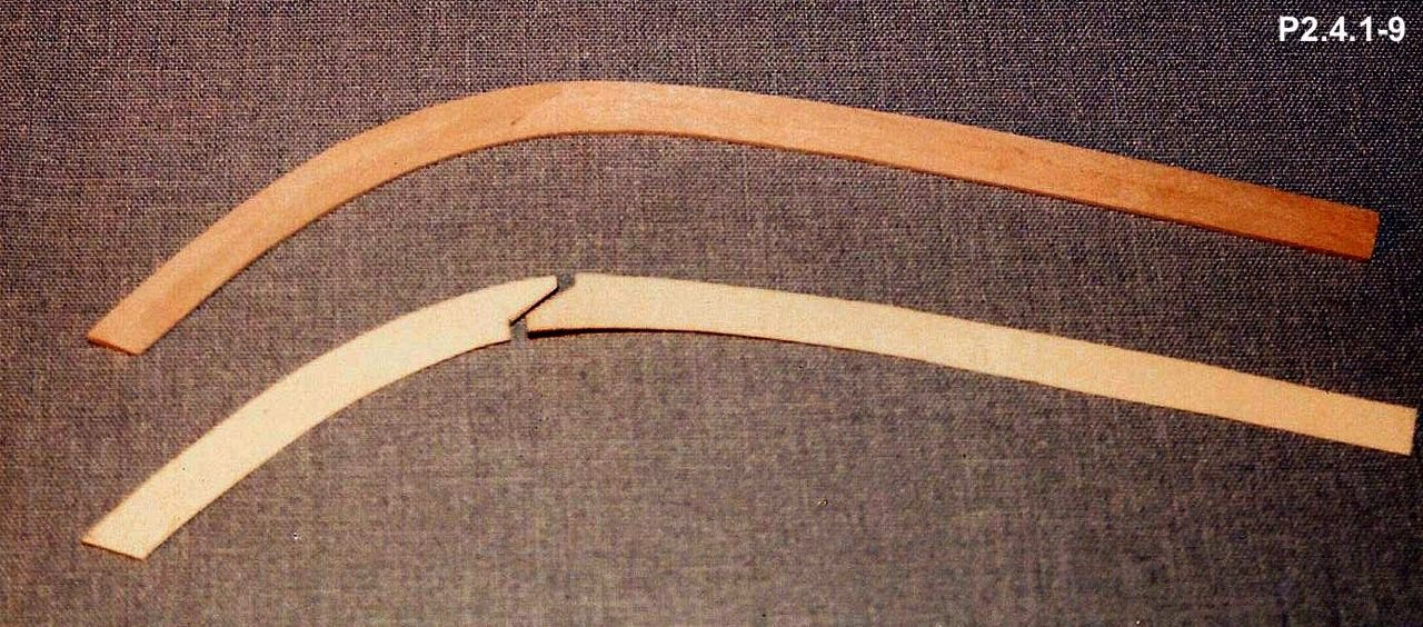
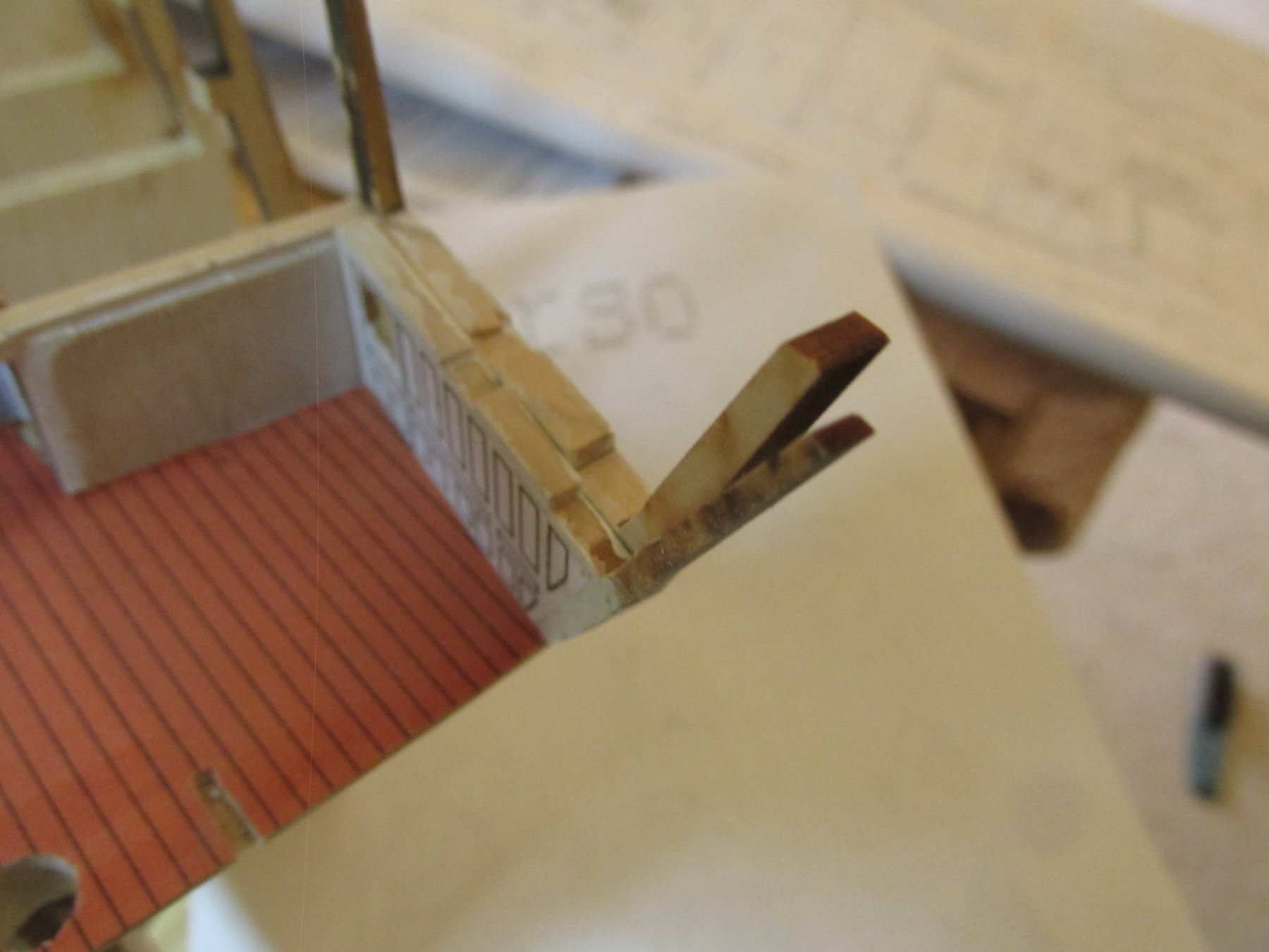
The Waterway and Planksheer
The waterway is made from 5/32” x 5/16” basswood stock. This is fine for most of the waterway but trying to bend this thickness of wood from bulkhead E forward around the inside of the bow would be exceedingly difficult. For this reason, the practicum directs the builder to use the ½” x 3/16” basswood stock supplied with the kit to make a two-piece pattern for the curve for each side of the bow as shown in the images below.
- DocBlake, Nirvana and CaptainSteve
-
3
-
You've got a great looking model and I hope mine will eventually would look as good as yours.
Jon
-
The Next Step
At this point I have no instructions on what to do next. The practicum and the kit instructions do not describe the kit bash I’m about to plunge into. After a number of false starts, I thought I would start by making the sills for the gun deck gunports only to quickly realize that I needed a reference point to measure from. This lead me to think I should use the floor of the gundeck, but I had chopped them down to make room for the plywood floor support and planking. If those cuts weren’t perfect, all my subsequent measurements would be off. Also, the wood needed to make those sills was going to be different than what the kit called for because I wasn’t planning to use a lot of the dummy cannons which require a “cannon barrel box” to be fabricated. When I started to research whether I needed to buy additional wood for “my” gunports or if I could recut the kit suppled wood, I checked the practicum to see what Mr. Hunt used for the “cannon barrel box”.
I discovered that he didn’t get to that stage until Chapter 3 in his practicum while I was in the middle of Chapter Two where he had come to the same question: where do you measure from? He stated:
QuoteWe will make and install the [spar deck] waterway first, then the planksheer [which sits on the waterway]. Once the planksheer is in place we have the defined bottom sill of our [spar deck] gunports. To establish the top sills or main rail, we will then install four planks on the inside of the bulkhead tops to form the bulwarks. These four planks will then establish the location of the main rail, which sits on top of the fourth plank. That will ensure proper framing of our gunports based on the wood stock provided in our kit. [The text in brackets are my notations for clarity]
Even though he is referring to the spar deck, the planksheer reference point will also apply to the gun deck. Hence, the next step is the construction of the waterway. This should be interesting as this element bends and is beveled 45° on the inner side and varying acute and obtuse angles on the outer depending where along its length it meets each bulkhead.
- Jack12477, Nirvana, CaptainSteve and 3 others
-
6
-
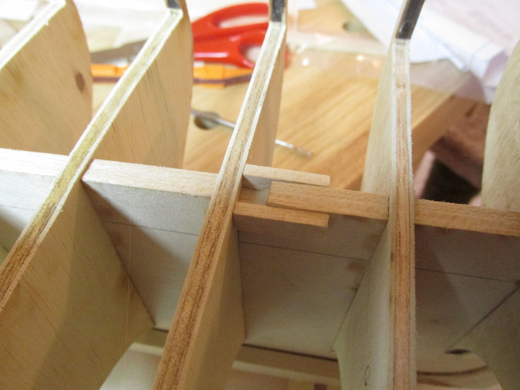
The kit offers, as an option, the creation of bulkhead stiffeners. I took the option. I discovered that as careful as I was making sure the bullheads were installed at eight angles to the keel, there were some differences in distances between the outer edges of the bulkheads from one side to the other by as much as 5/32”. To counter act this, the stiffeners were cut the average of the two sides. So, if I added 1/32” to the port side stiffener, I reduced it by 1/32” on the starboard. This forced the bulkhead to twist back to a right angle.

- CaptainSteve, Blue Pilot, DocBlake and 5 others
-
8
-
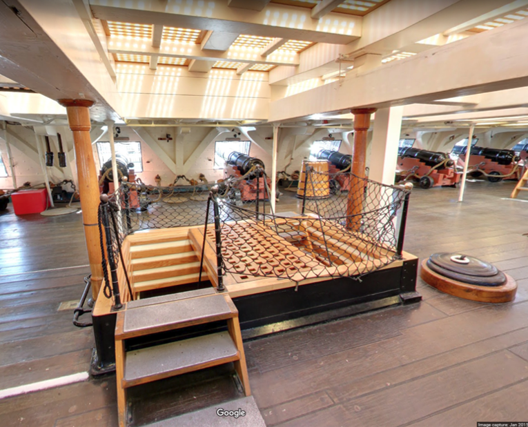
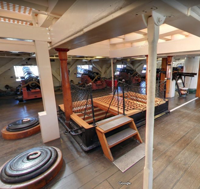
Then my curiosity got the better of me. I wanted to see what the gun deck looked like on the model. I will have to know where the ladders are located and whether I need to make those or gratings if I leave the stair openings covered. Using the US Navy plans, I matched their scale to the kit’s and printed the layout (3 sheets). These will also be used to make the template for the gundeck support flooring for the planking.


- Tigersteve, CaptainSteve, kmart and 4 others
-
7
-
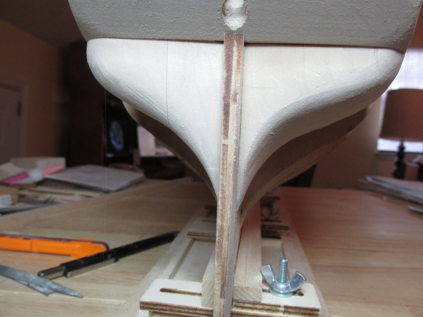
What to do next? What to do…According to the kit instructions, I should be attaching the transom extensions (the aft side of the quarter galleys) but I don’t want to add those on until I’m actually working on the quarter galleys. I’m afraid I could snap those off by accident. But in looking at the transom, I thought I’d better check how the planking boards will curve into the stern. I discovered that I needed to trim more wood off the filler blocks. You can see in the image below, the subtle but significant difference between the untrimmed port side and the trimmed starboard side.

- SUBaron, CaptainSteve, Tigersteve and 2 others
-
5
-
Thanks for the compliment Captain, flattery will get you everywhere with me!
Mast Reinforcements
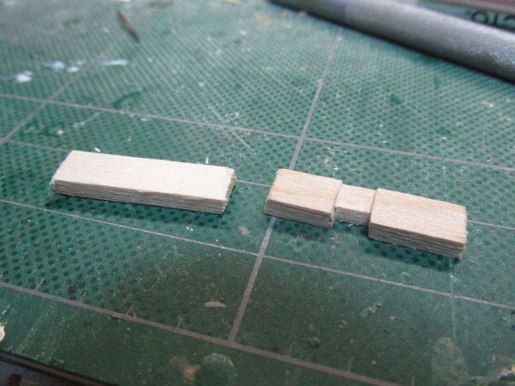
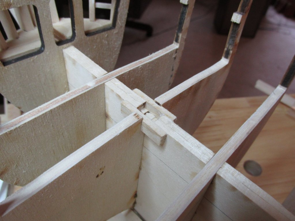
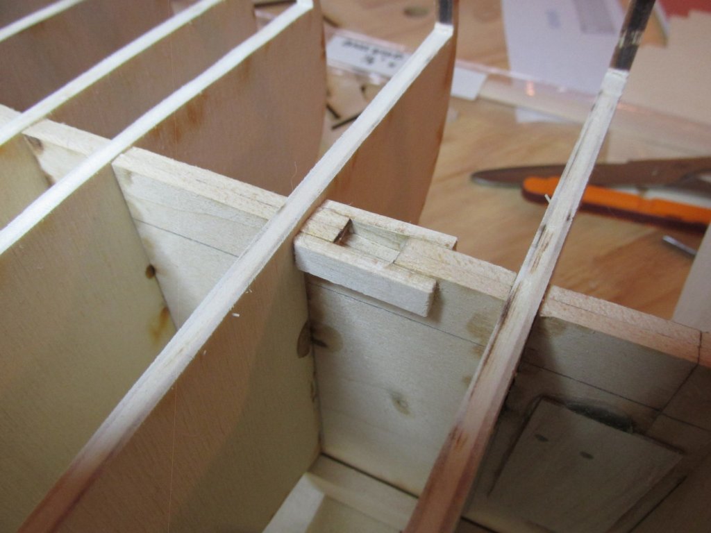
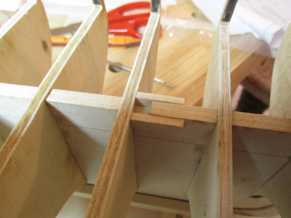
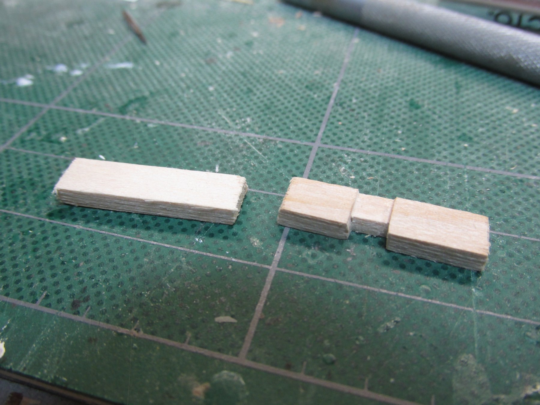
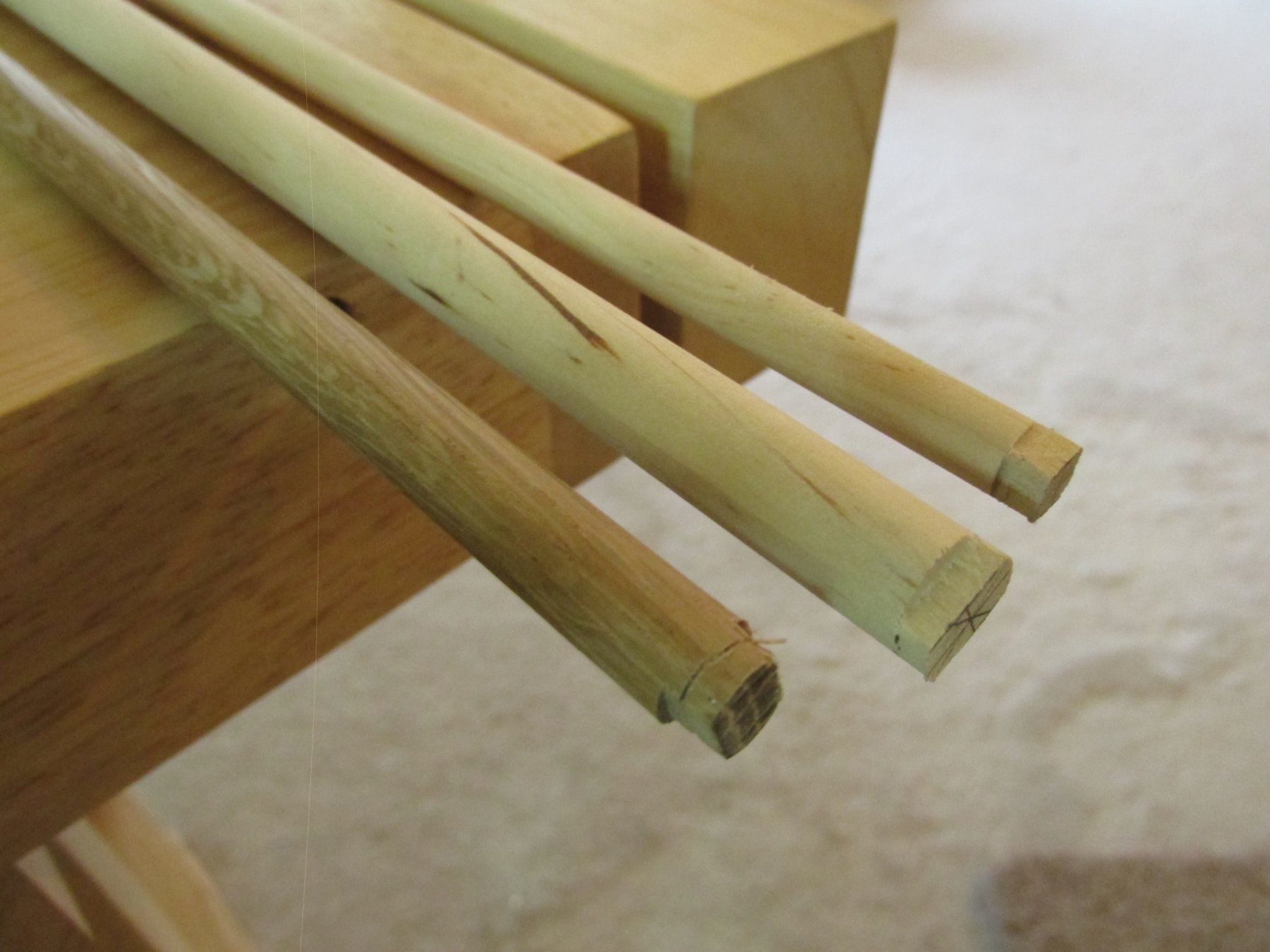
Before I go off script again, the next items to be added per Mr. Hunt’s practicum and the kit instructions are the mast reinforcement. These add sides to the mast slots in the keel bulkhead. The main and mizzen mast are constructed the same. The foremast has the added complication that it also is in a slot of a bulkhead. The kit plans state that the pieces are to be 1/8” thick, no width or length is specified. The practicum calls for 1/8” x 5/16” stock (basswood). The problem is that the kit does not supply 1/8” x 5/16” stock. I used 1/8” x ¼” stock which close enough. The main and mizzen masts reinforcements were cut to length by eyeball and glued into place. The foremast had to be notched along one side to allow for the bulkhead to slide by and notched at the bottom so that it could sit low enough on the bulkhead to cover the keel notch. Once those were done, stock dowels for the fore (3/8” ᶲ), main (7/16” ᶲ), and mizzen (5/16” ᶲ) masts were notched to create a mortice to fit into those slots.

- Jack12477, Geoff Matson, DocBlake and 2 others
-
5
-
Glad that I could be of some help. Some of that stuff really requires fine dainty fingers and a delicate touch, not to mention patience and tenacity. We're lucky if we have one or two of those attributes. Looks good though.
Jon
-
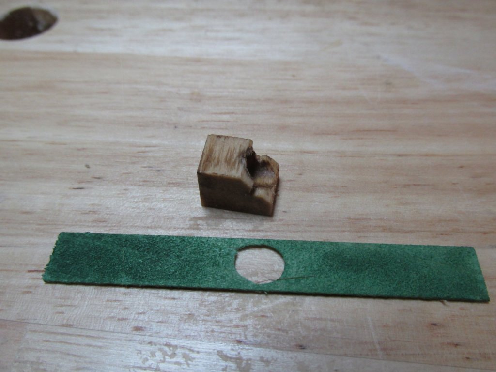
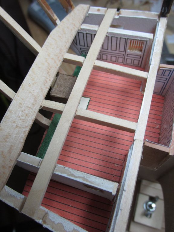
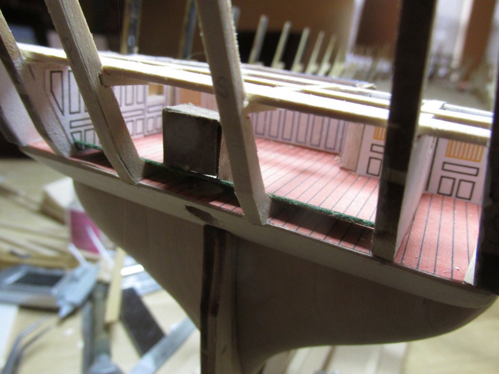
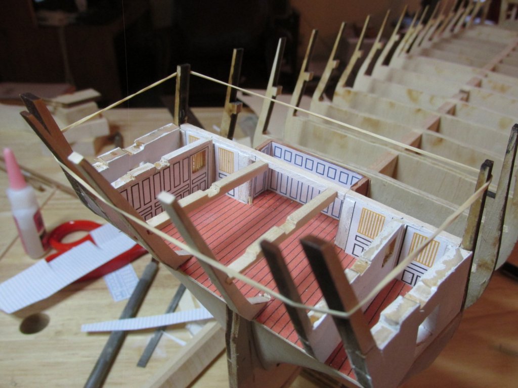
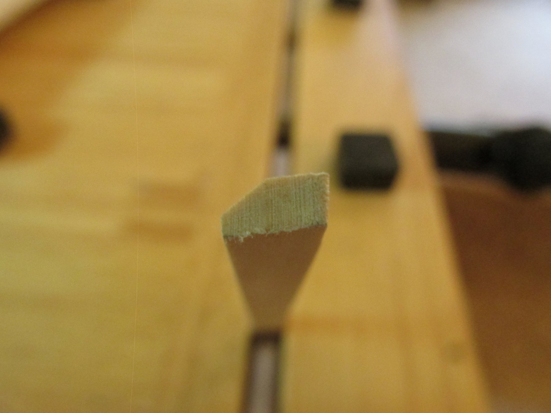
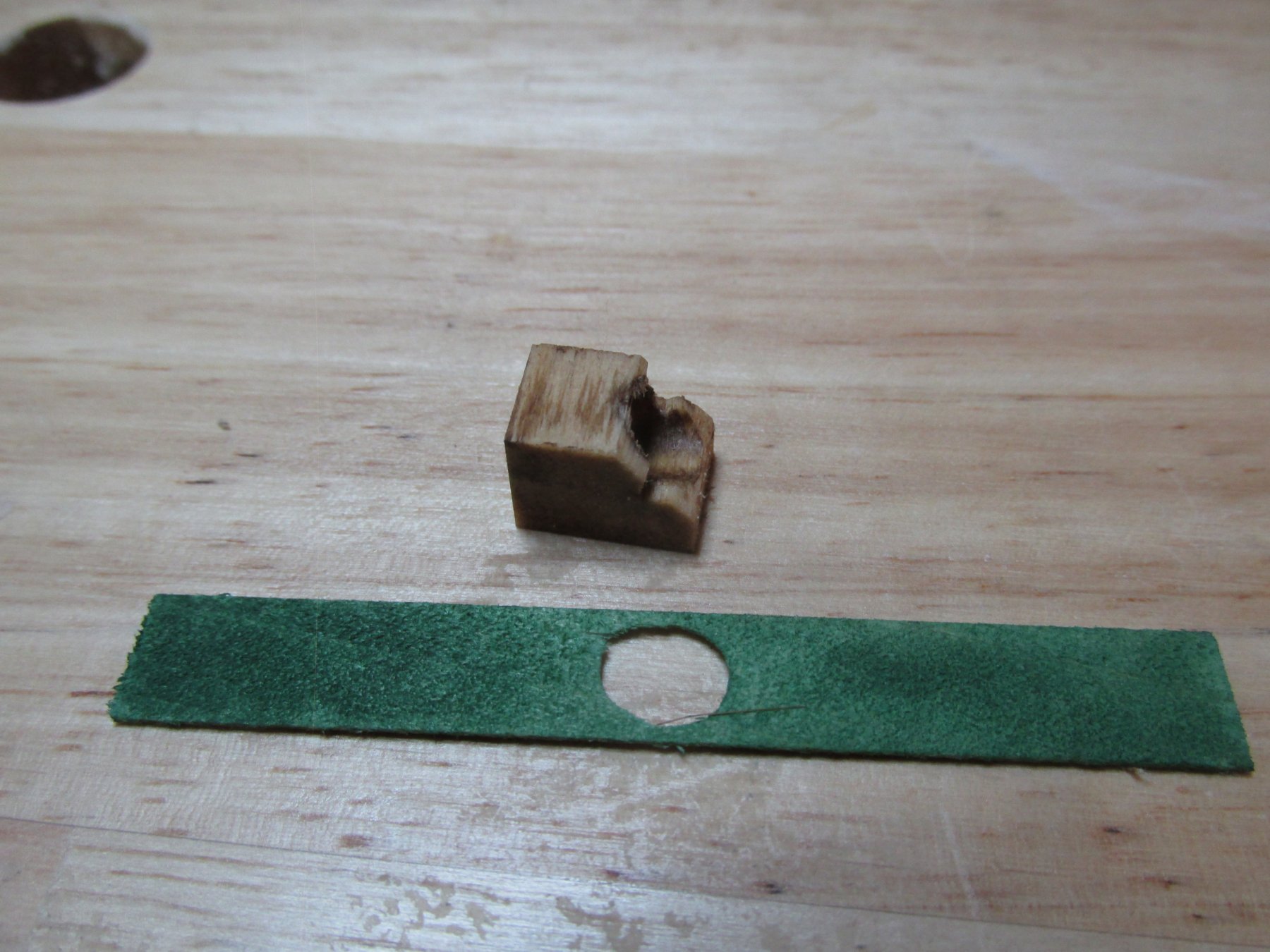
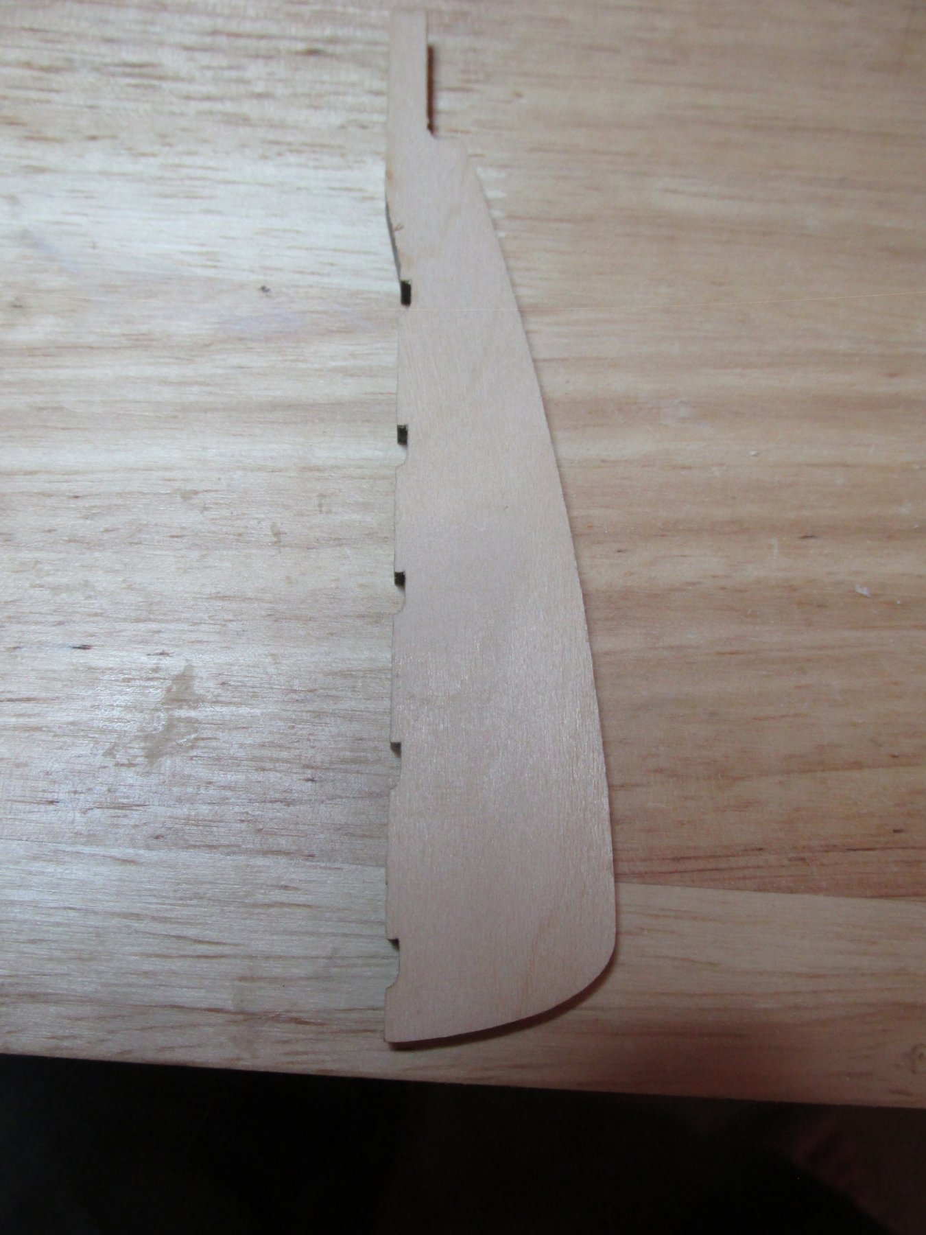
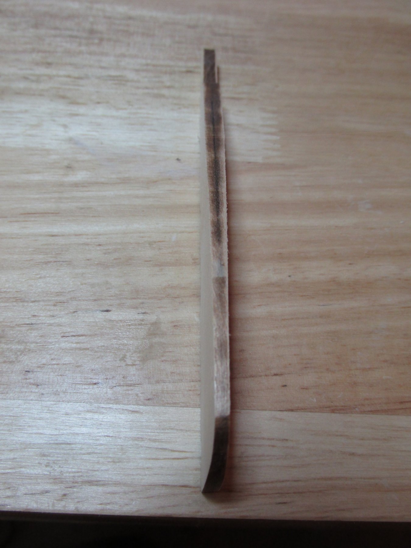
My first attempt to create the rudder top box also failed. I had tried using a block of basswood with a hole drilled into it As I tried to increase the hole size to accommodate the rudder shaft, it obviously got closer and closer to the edge of the block till it structurally failed. The green strip (1/32” basswood) reflects the internal counter bending toward as seen in the actual photo above.
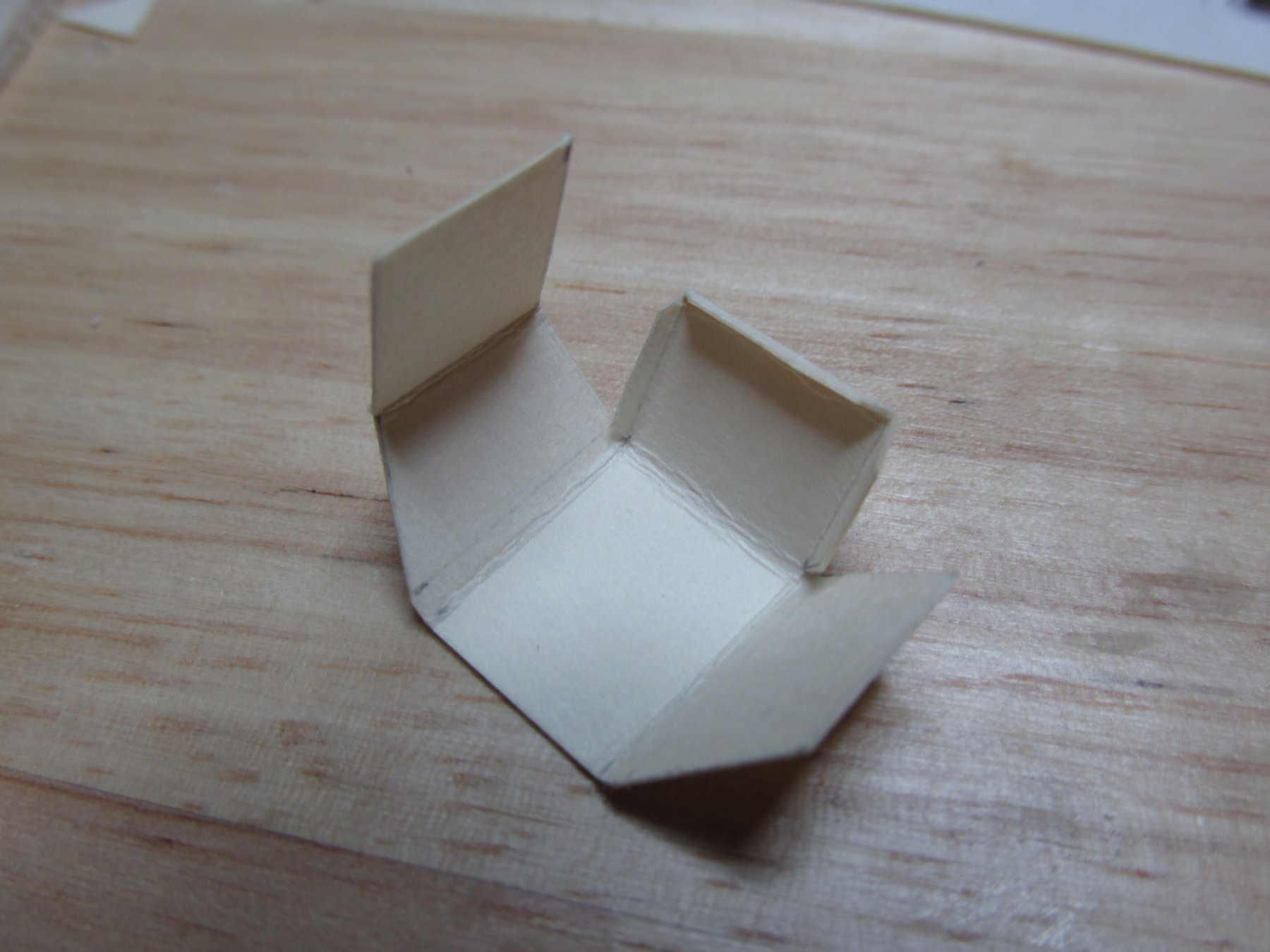
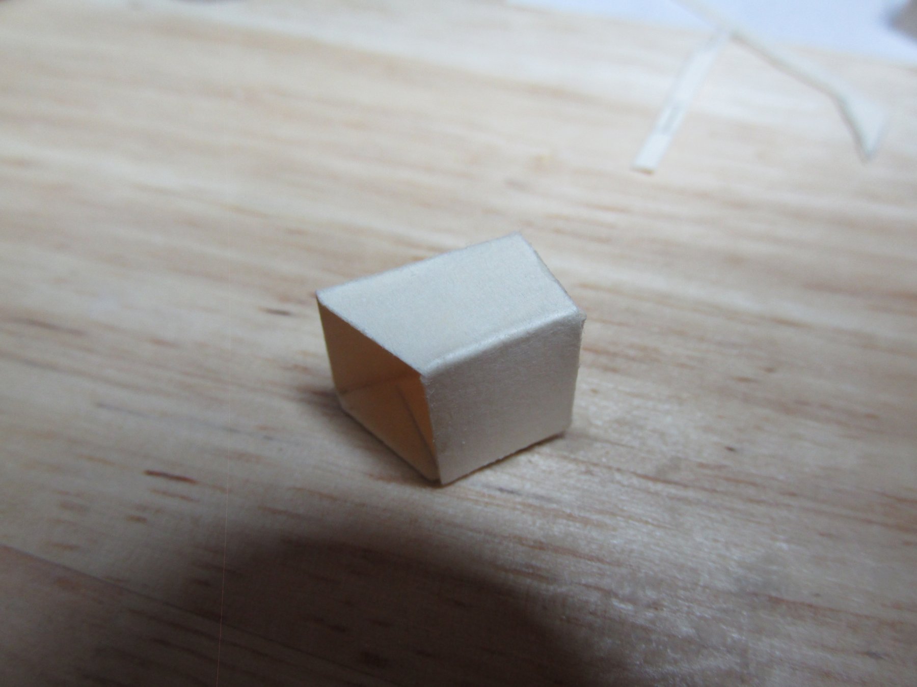
Because the rudder top box will not be seen clearly, it did not require much detail other than its overall shape. That meant it didn’t even have to be made from wood. My second attempt, I tried cardstock. Using a single piece of cardstock, I fashioned a pattern with glue tabs which was then folded into shape. It worked. I gave it a splash of stain and you would swear it was made from wood.


-
Rudder and Rudder Head Box
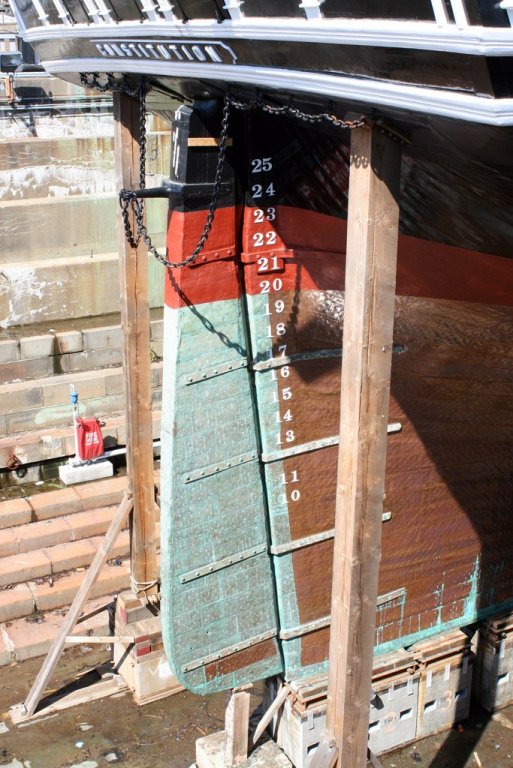
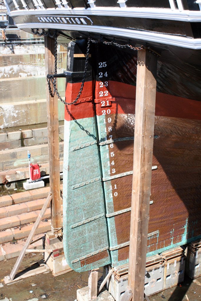
Continuing with my idea of creating an essence of this space and not an actual reproduction, the last major element to be installed in this area was the Rudder Head Box. Since this obviously involves the rudder fitting into the rudder top box, this was a good time to finally shape it. The rudder tapers down top to bottom from 3/16” to 1/8”. It also tapers near the bottom, forward to aft 1/8” to 3/32”. This was done with a very light and delicate touch with the disk sander and elbow grease with a block sander. Interestingly, the plans call for the rudder shaft to be “round stock” but I believe that is not necessary. That part of the rudder is not seen. I checked a lot of the model builds where they show that detail, and no one fully rounded the shaft if they bothered at all. The pictures below show the actual ship rudder in which you can clearly see the taper and my rudder in which I attempted but failed miserably to show the taper I created.
- coxswain and Geoff Matson
-
2
-
In my last post, I stated that I thought the #3 frames’ “rooster tail” didn’t seem to match up with the other frames’ “rooster tails.” That still may be true, but I decided to leave it for now. Hopefully I’ll know better what the true angle should be when I start building upon it. For all I know at this point, it may be correct. So., I took the plunge and glued the #2 frames into place.
The last of the inner frames are the completely modified ones. The more I looked at those frames, the more I disliked them. They didn’t have enough “meat” on them. I wanted something as robust as the original #1 frames in terms of thickness. So, I rebuilt them using the center wood that was punch out and left over from the ship’s boats shells. The vertical and horizontal pieces were then glued into place. Once these were in place, it became obvious that some of my notches for the cross beams did not line properly. Those had to be adjusted. As planned, my cross beams are 1/16” thick as opposed from the plan’s 1/8”.

- Tigersteve, hexnut, CaptainSteve and 2 others
-
5
-
Thank you for the fore studding sail brackets images. I really appreciate it.
You brought up another subject that has been in the back of my mind: How do you safely move these delicate models? I have heard of numerous tales of damage done when putting them in a car and the car has to make a sudden stop, etc. I'm curious as to how you're going to it. It would be even better if you could photograph the process. A some point, in my future, I too will have to move my models, so here is another lesson to be learned.
Jonathan
-
Quote
The plans are a bit unclear on what these brackets look like, but I had pictures of the ship that I took that show them very clearly. I can post those if folks are interested.
One can not have too many pictures of details. You never know which ones you'll need. So yes, please post those images.
BTW, I hope my effort at this build can compare to your wonderful build, and so many others. We all learn from each other.
Jonathan
-
Now tell they weren't fun to make! Very nice job.
Jon
- SawdustDave, Piet, Canute and 2 others
-
5
-
I can see that I have my work cut out for me when I get to this stage. Nice work!!
Jon
-
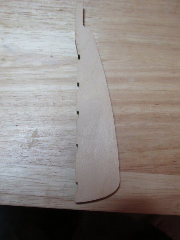
Then I noticed another problem. Now that I’ve got the outer #3 “rooster tails” spaced horizontally correctly, they do not have the same aft angle as the inner frames. I had noticed this earlier, but thought it was to compensate for the counter’s curve. It may have been, but not to this extreme. I know others have had problems with this area and have rebuilt the transom corners. It may come to that, but first I want to install the inner frames to calculate from the inside out the final shape of the #3 frame.


- Nirvana, CaptainSteve and Geoff Matson
-
3


USS Constitution by SawdustDave - FINISHED - 1:60th Scale
in - Build logs for subjects built 1751 - 1800
Posted
Only the most discerning eye would know that there should be a plate and that it was missing. 99.99% of the observers of your model wouldn't have a photo of the real ship to compare and be observant enough to note the omission. You however are in that 0.01%. If this is something that will eat away at you, then by all means fix it. If however, you claim artistic license, well then, beautiful work, you should be proud.
Jon