


JSGerson
-
Posts
2,171 -
Joined
-
Last visited
Content Type
Profiles
Forums
Gallery
Events
Posts posted by JSGerson
-
-
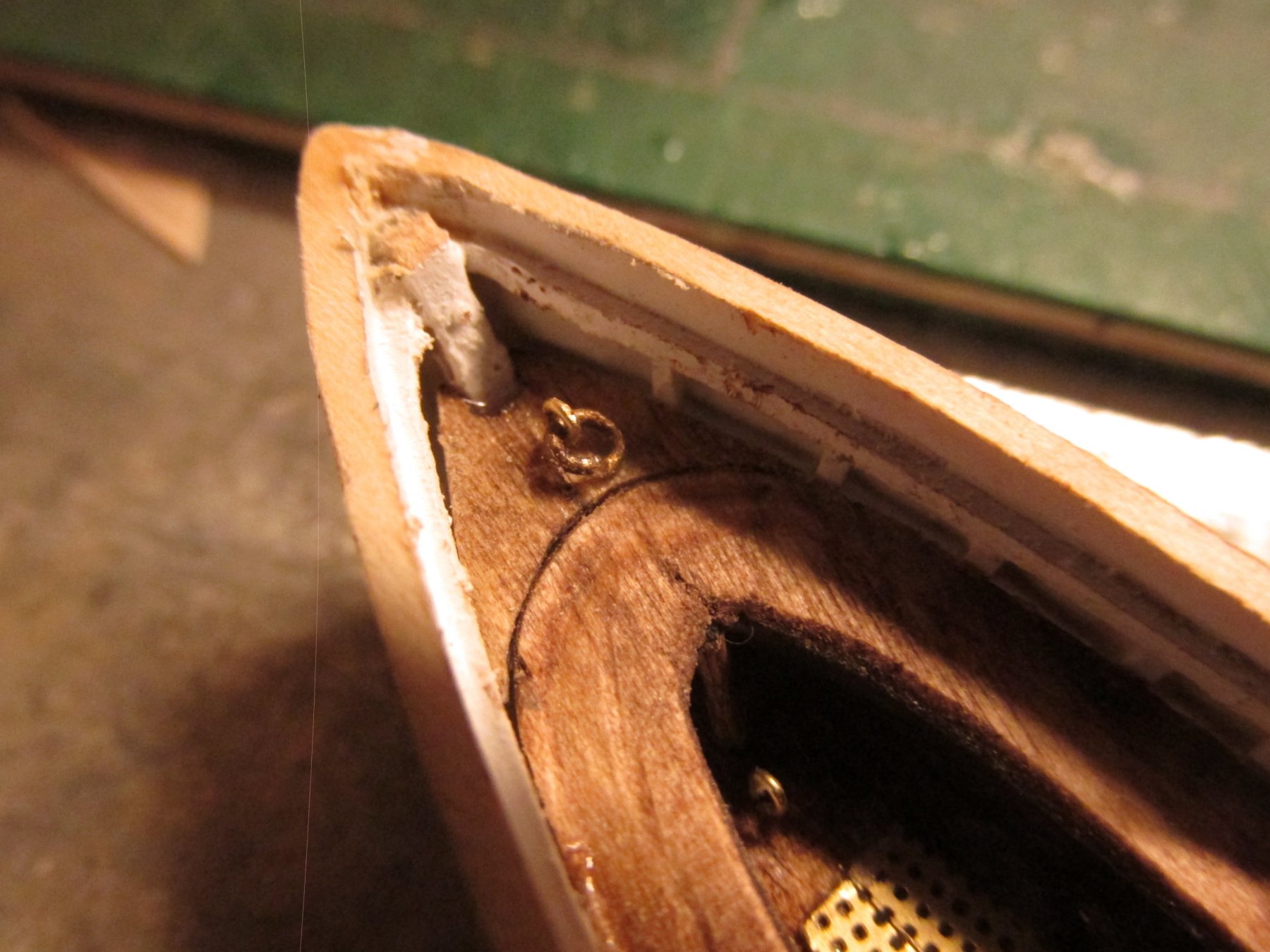
This a complicated area of the boat. The bench must fit in a corner with sloping sides coming to an apex at the stern post. Between the stern post and the bench there is supposed to be a covered area with a grating on top, a backrest behind the bench, all siting on a platform that has a ring assembly accessible when the grating is removed. I chose to make this platform separate from the bench although in hindsight, I could have made both the bench and platform from one piece of plywood. Here are the two components stained mahogany before installation and glued into place.

- Geoff Matson, MEDDO, CaptainSteve and 1 other
-
 4
4
-
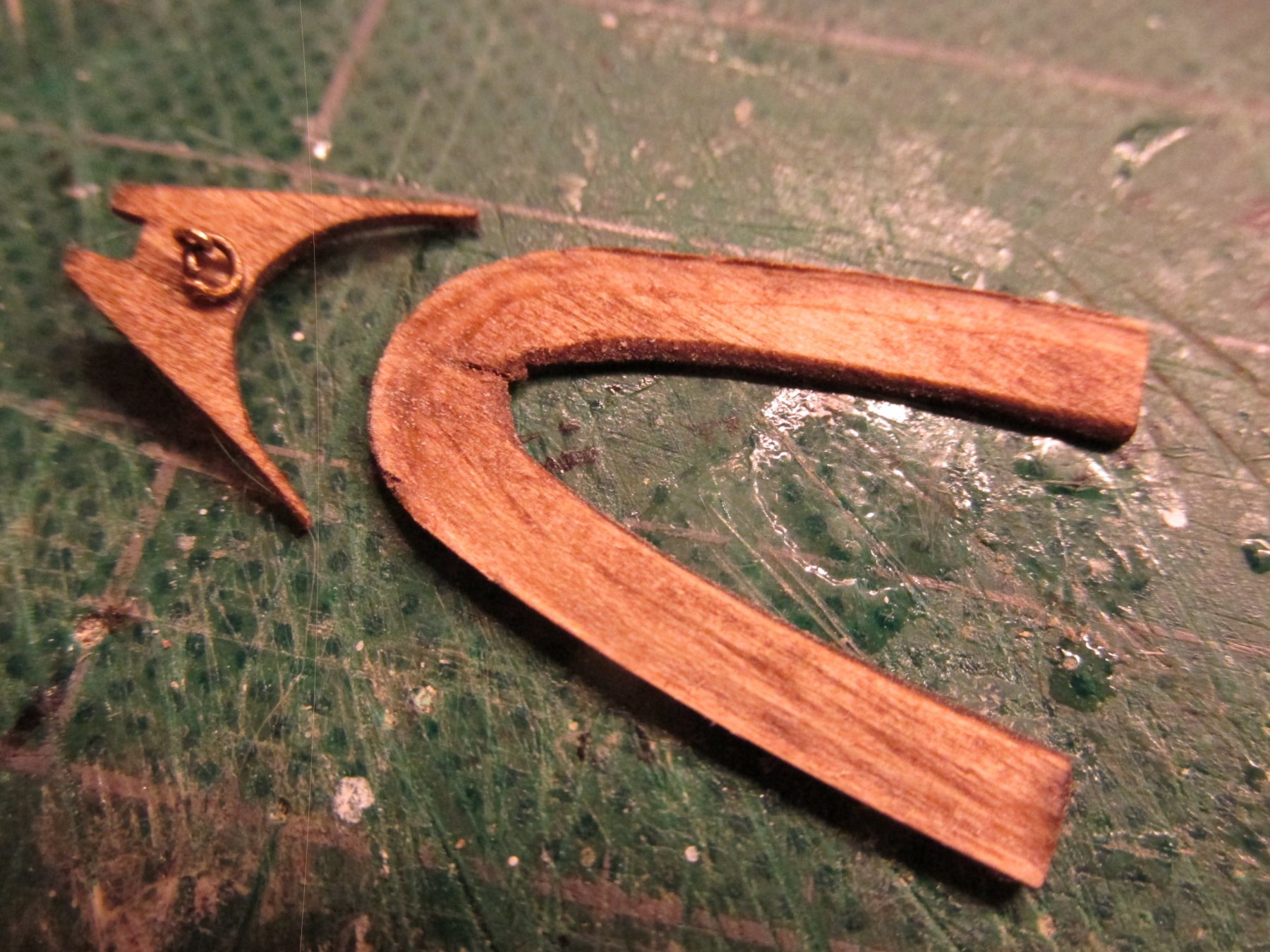
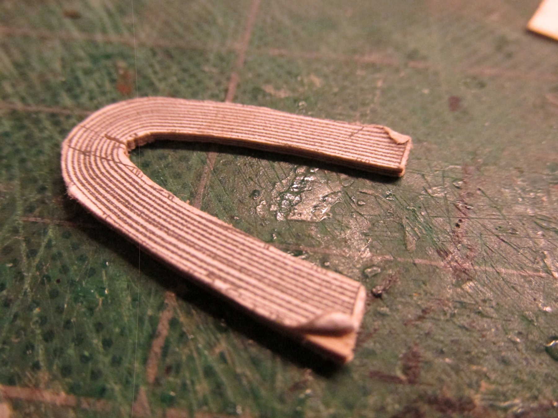
Gig Wrap Around Bench Seat
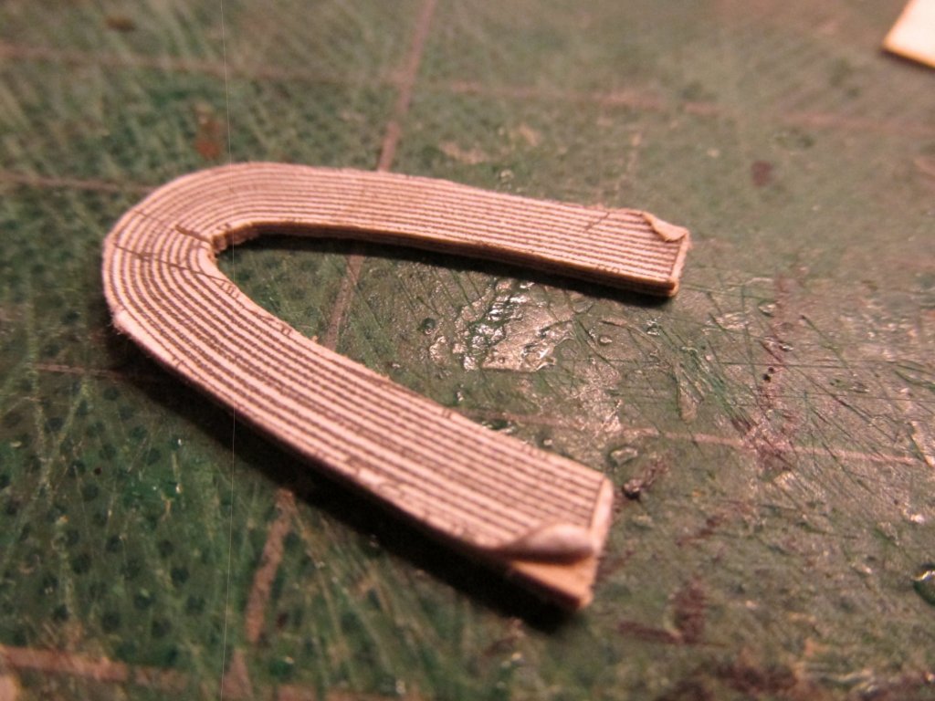
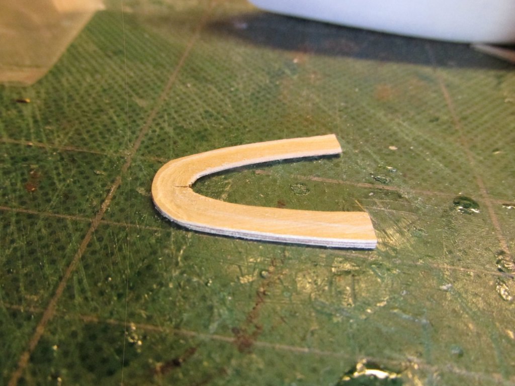
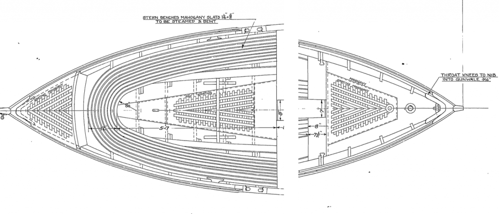
The wrap around bench seat presented me with a conundrum. In the actual boat, the seat was made up from concentric slats separated by a space. One can see that in the template I made from the US Navy plans. However, the scale was just too small for me to simulate the slats and spaces. So, like others before me, I used to make the rough cut from 1/32” plywood. I did try to contour the seat profile so it would fit a scale tush as shown in the plans. I’m not certain whether I was successful at that or even if it was, would anyone even notice it. It was then dry fitted until if fit properly into position.
- MEDDO, Geoff Matson and DocBlake
-
3
-
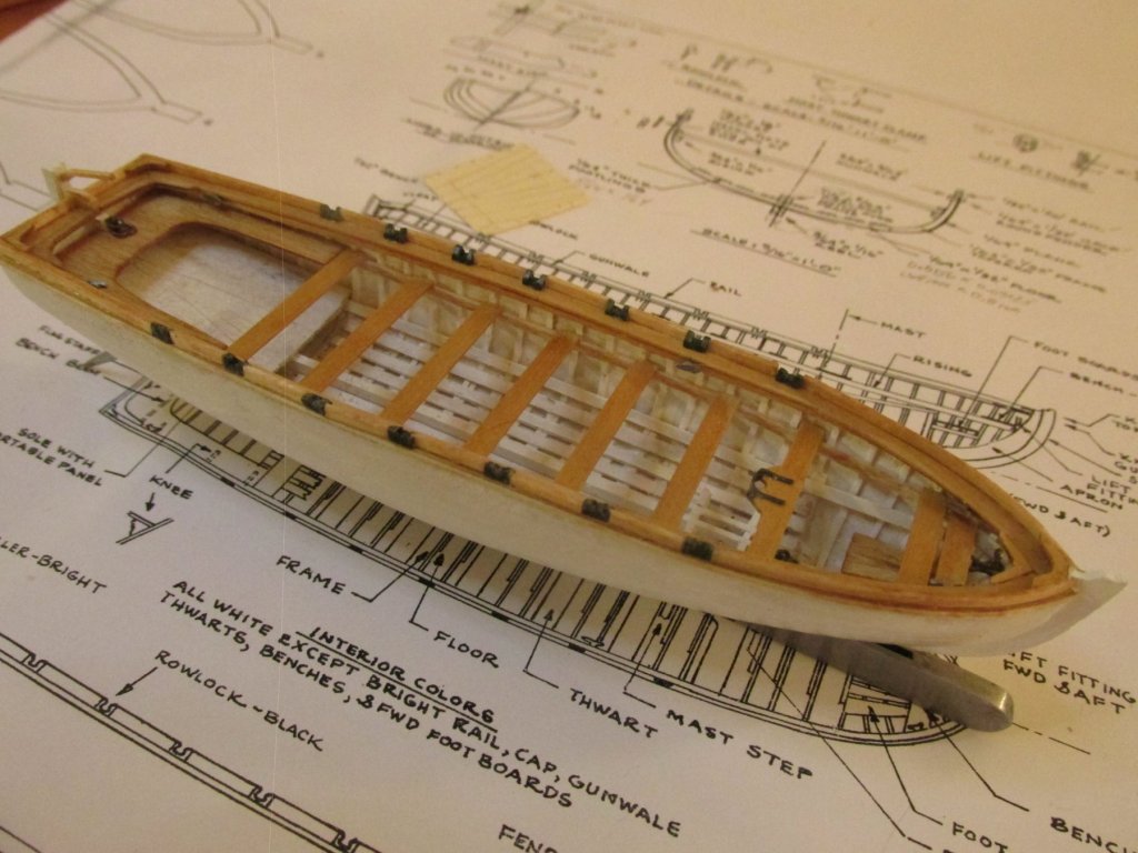
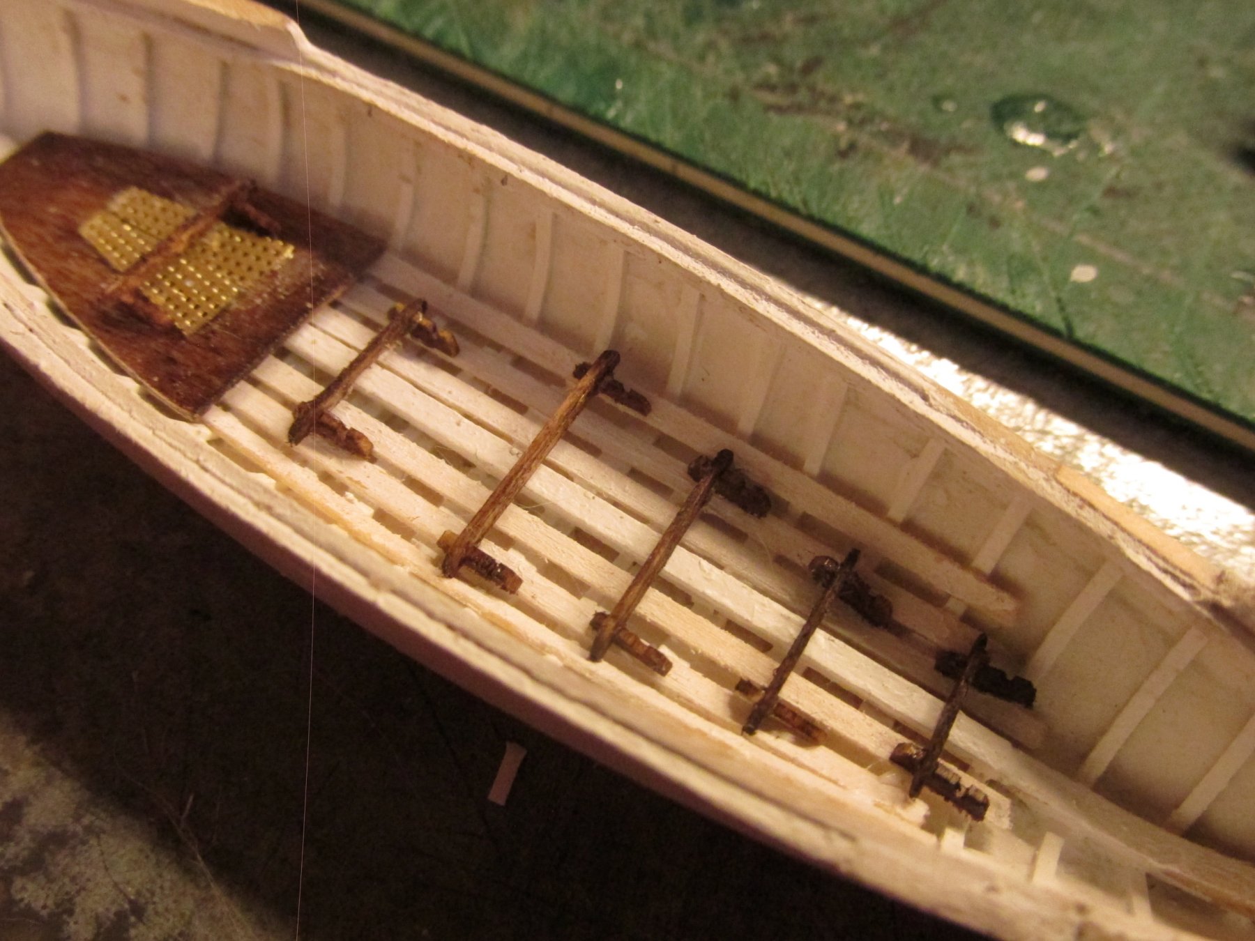
Remaining Gig Footrests
The remaining 5 footrests were constructed and installed in a similar manner as the one over the grating. The footrest lengths did vary though.

- Blue Pilot, DocBlake and CaptainSteve
-
3
-
-
-
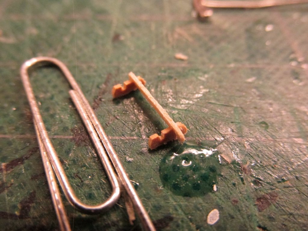
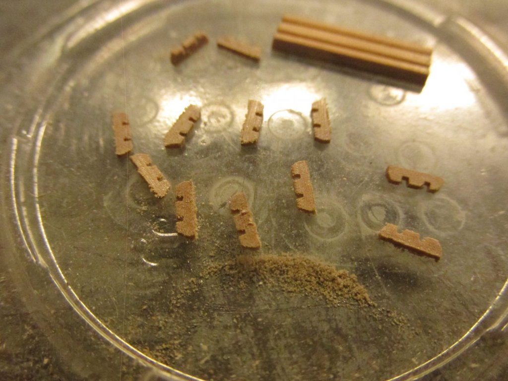
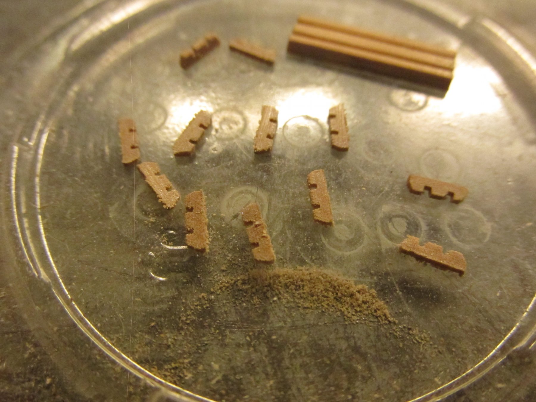
The footrest was made from 1/32” x 1/64” basswood, assembled with the supports, and stained mahogany. It was then set into place on the sole.

-
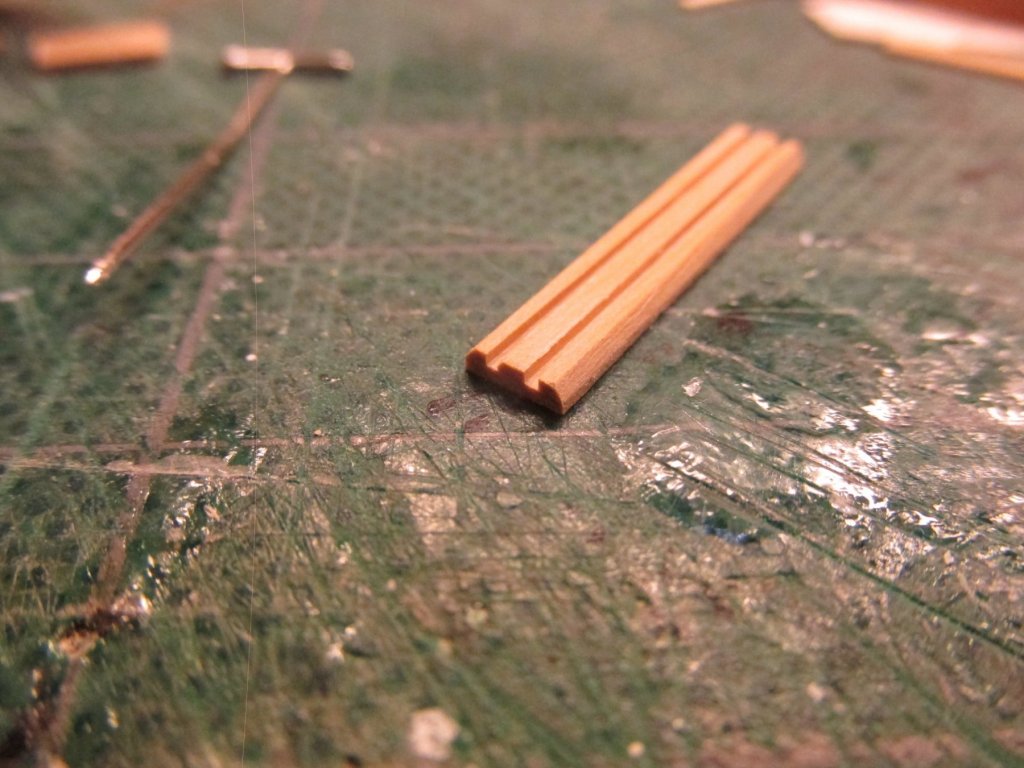
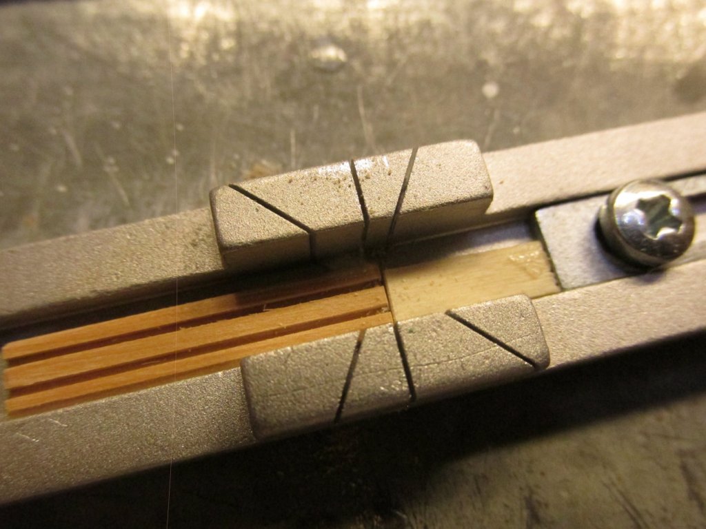
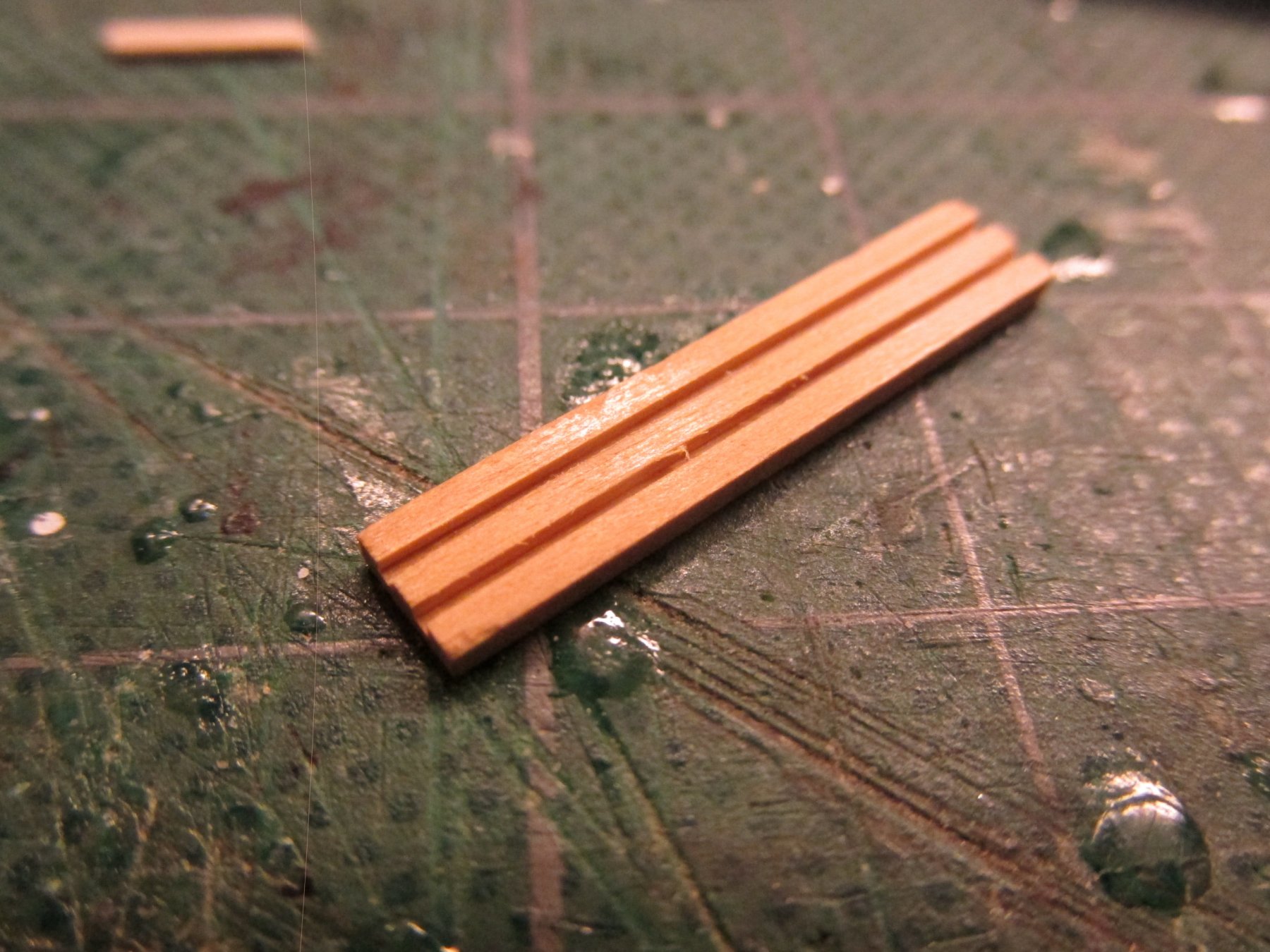
In addition to the grating, the sole also has a rower’s foot rest. This was made first cutting two channels into a 3/16” x 1/16” piece of boxwood and beveling the edges. Using the razor saw and miter, I sliced up twelve 1/64” thick foot rest supports. To use the miter’s stop, I had to use a piece of wood as an extension because I couldn’t set the stop to 1/64”.

-
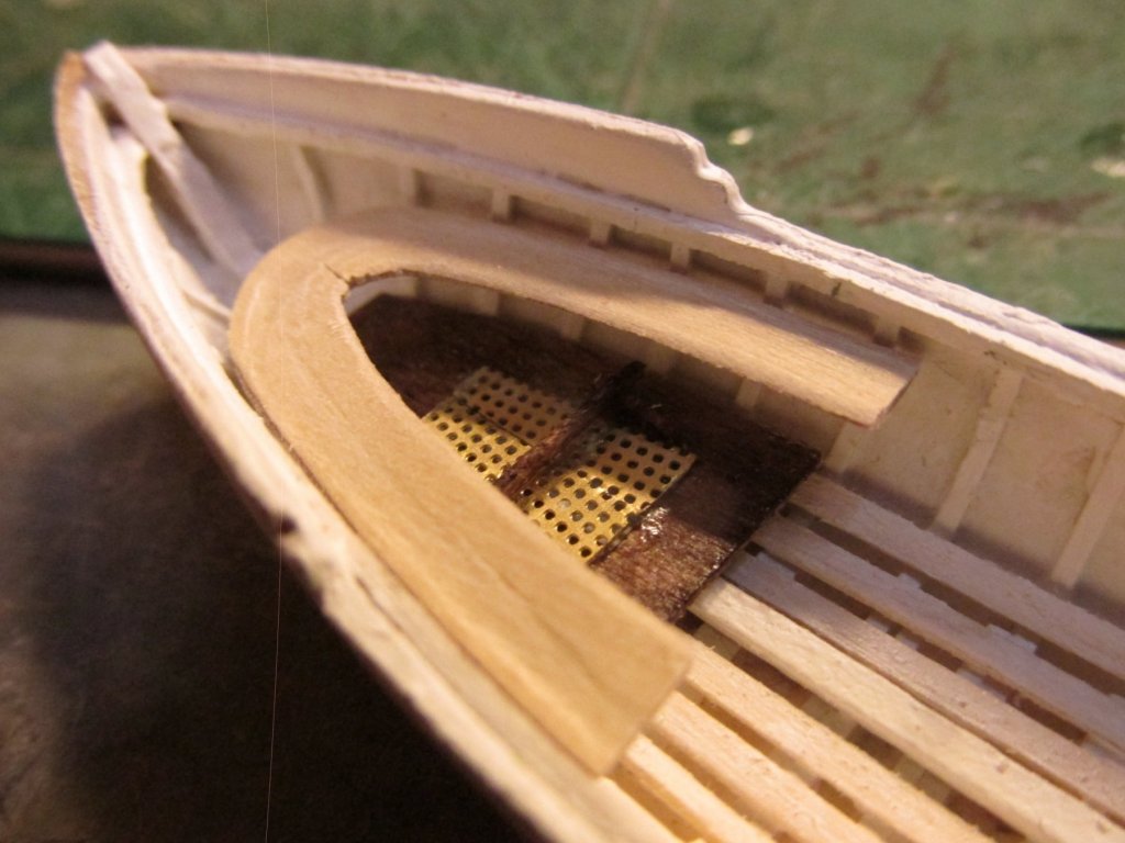
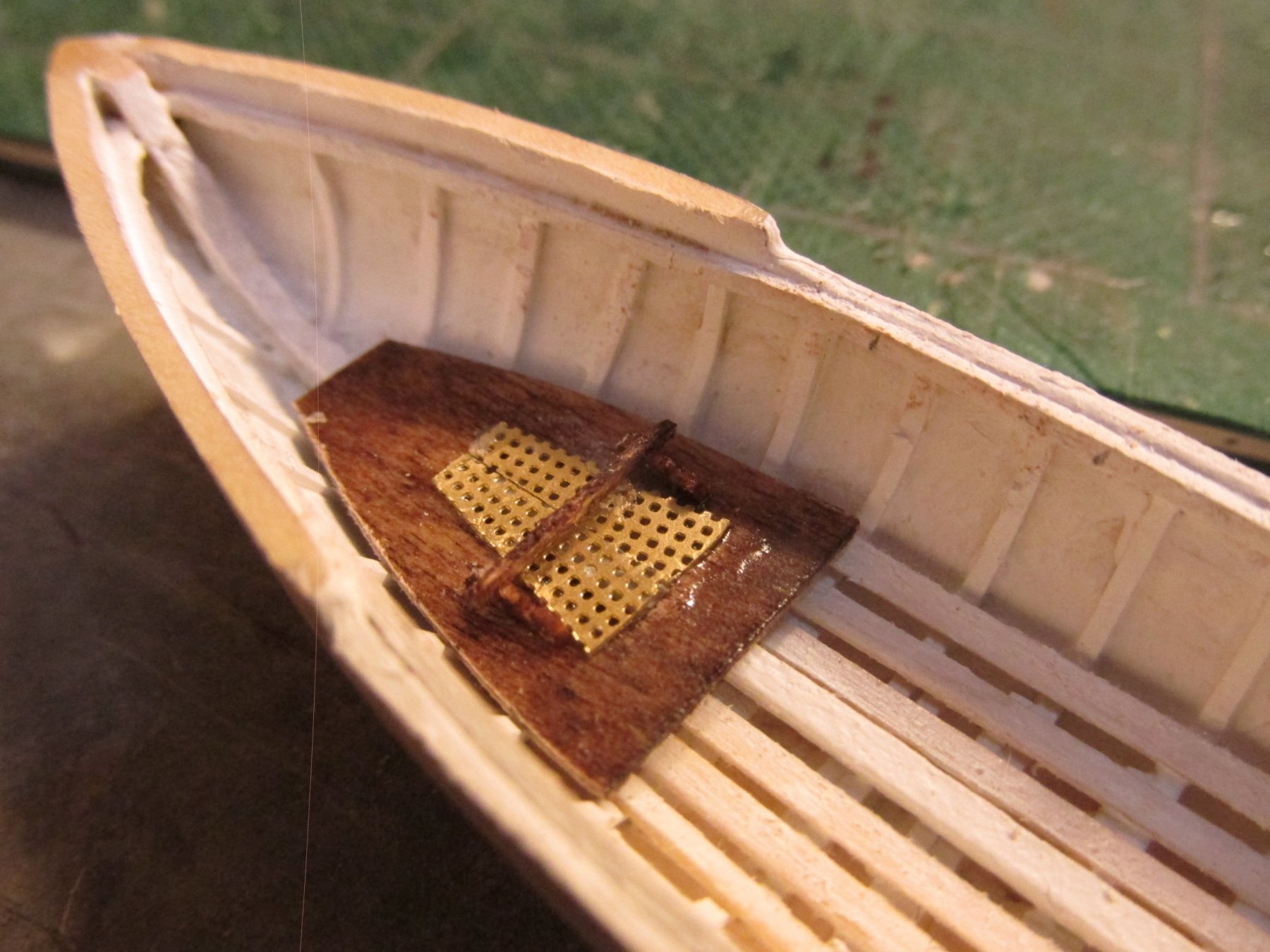
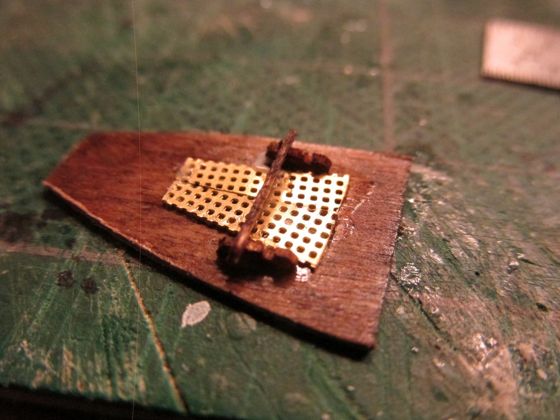
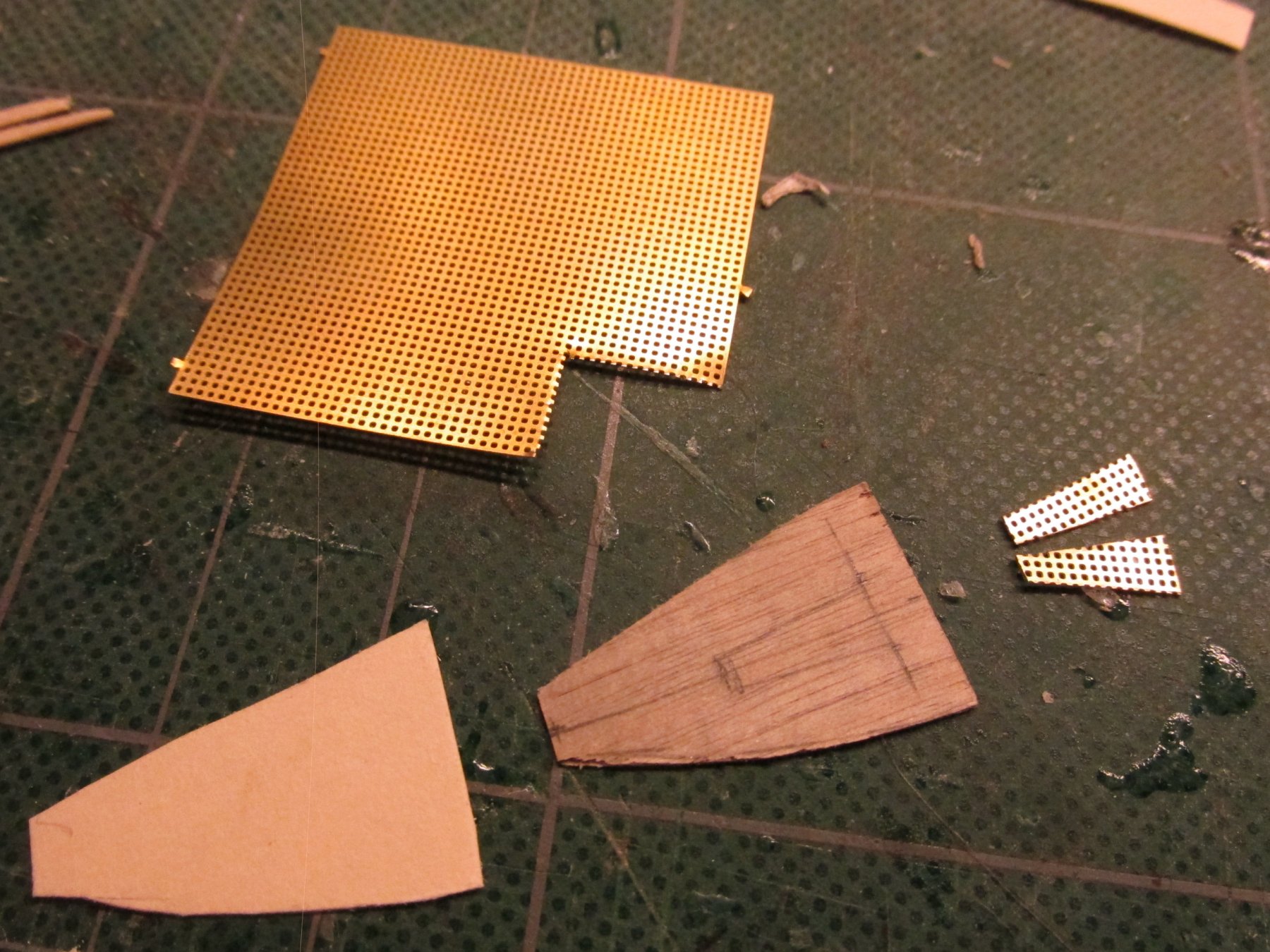
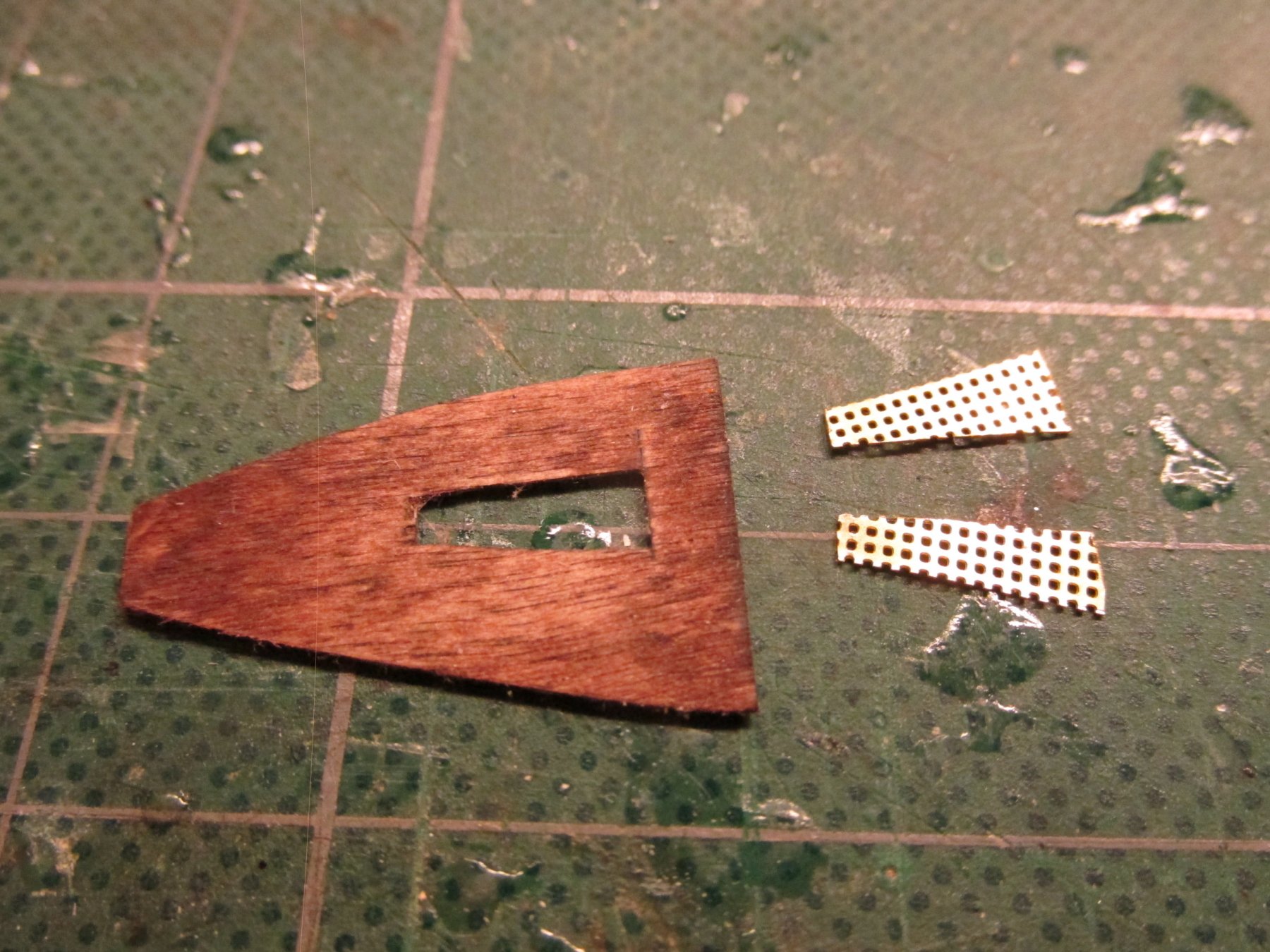
I thought about how to reproduce these. The problem of course was scale. 1/76.8 is just too small, at least for me. The kit however provided a compromise. It provided a photo-etched mesh to use in lieu of creating one or just faking it. From what I have seen on other builds, the mesh was cut such that they ended up with a fine square cross-hatch pattern. I wanted to emulate the chevron pattern.
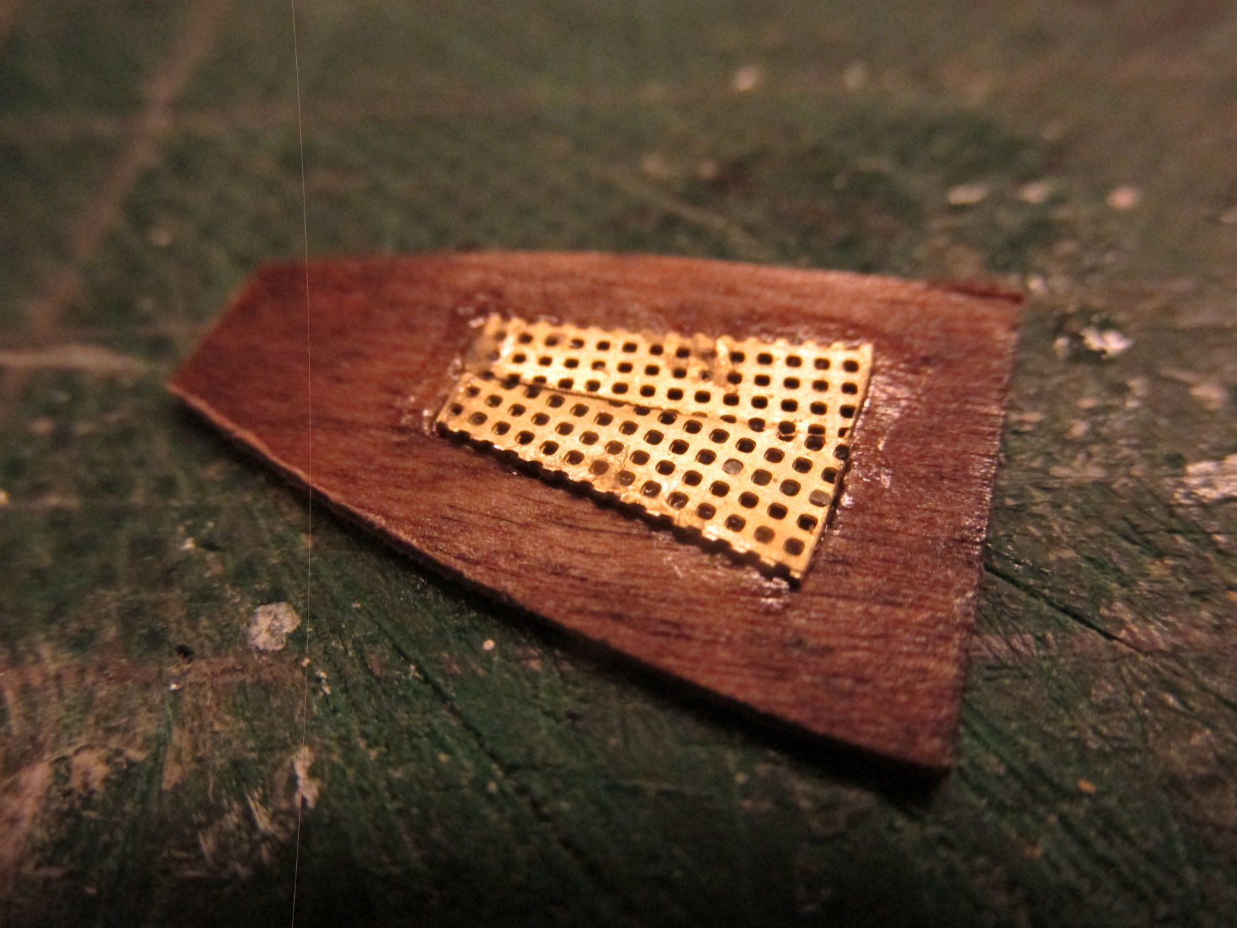
First off, I made a pattern for the sole and then made the sole itself from 1/64” plywood and stained it mahogany. An opening was then cut matching the plans. Instead of just cutting out the mesh to the shape of the grating, I split the mesh such that when the two pieces were put together, the mesh holes were on an angle, more reminiscent of the actual grating. Looking at the plans, I also noticed that the grating did not have a frame around the edges due to the method the actual grating was made, so I deliberately made sure my cut mesh had ragged edges. The two pieces were aligned and CA’d into place over the sole opening.


- DocBlake, usedtosail, CaptainSteve and 3 others
-
6
-
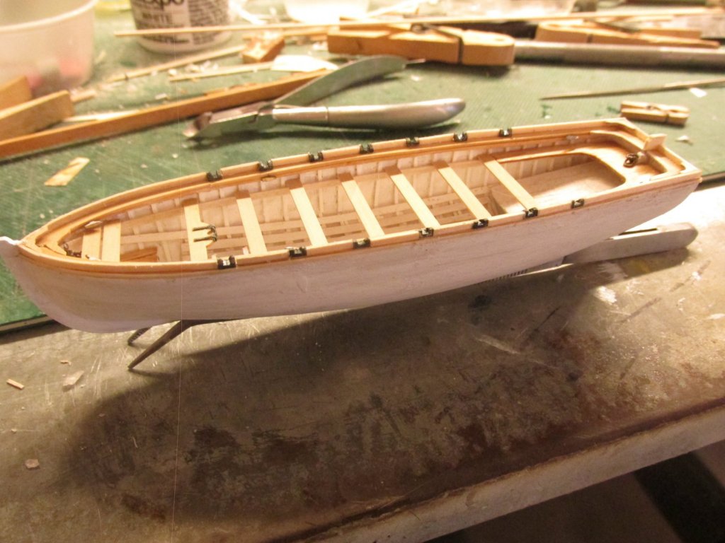
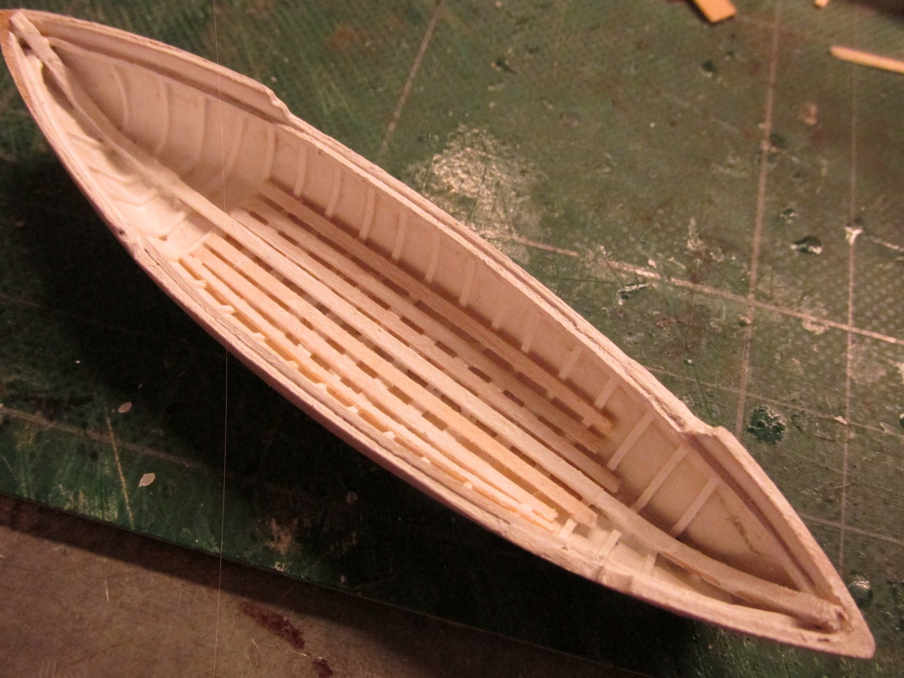
Gig
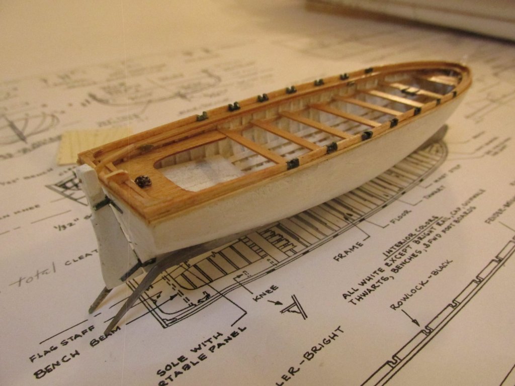
The gig, when last worked on, only had the ribs and keelson installed. So now the question was, what to do next. The kit plans basically state, follow the plans and make the boats. The practicum does not put in all the detail I want to include. Other build logs don’t have the detailed step by step guidance I was looking for.
So, after a number of false starts, I plunged ahead. Working from the bottom up, inside to outside progression, I decided that the sole at the stern was a good place to start. The sole has a unique grating. In fact the gig has three unique gratings. They look like chevrons instead of the typical square cross-hatch patterns…and they have very fine openings.
- MEDDO, Duanelaker and CaptainSteve
-
3
-
That is a LOT of fine detailed work in such a short period of time. I'm still dinking around on the second of the four ship's boats after numerous months of "work." 8-)
Jonathan
- Canute, md1400cs, CaptainSteve and 3 others
-
6
-
Quote
As a result of my skillful application of that method, the piece is currently soaking a a shallow tray of paint stripper.
I like your sense of humor. Sometimes that's all you have to keep going 8-)
Jon
-
-
This one from The Young Sea Officer's Sheet Anchor by Darcy Lever does talk a bit about how the boom is launch. The small ones appear to be literal pushed by hand while there is some rigging (temporary?) used for the larger ones
- CaptainSteve, xken, mtaylor and 1 other
-
4
-
-
From the book Rigging Period Ship Models by Lennarth Petersson, I found these diagrams for studding sails. I hope these are what you are looking for.
-
When I wrote the above comment, I did check your log for the construction of the boat but didn't go back far enough. I had forgotten that you indicated that you followed my log in making the boat.
Installing the boat requires that you first install the spare masts to support the boat which need to be lashed down first, and then the boat mounted and tied down on top of those. It's the tying of those lines which will become difficult as you add more rigging that may interfere with that process.
I tried to work from the inside out, bottom to top. The boat is inside bottom.
Jon
-
You make it look so easy!!!
Jon
- CaptainSteve, xken and Canute
-
3
-
The tiller was made from boxwood to resemble the US Navy plans and inserted into the rudder stem where a hole had been previously drilled. An additional hole was added on the rudder where it jets out midway down. A final coat of Minwax Polycrylic was added to the whole model to protect the bare wood and add a little gloss to the painted sections as well. One down, three to go.
- CiscoH, MEDDO, usedtosail and 6 others
-
9
-
The rudder was then painted white with two coats, re-enforcing plates added where the tiller is inserted into the rudder stem, added “metal” straps made out of painted card stock, and pins to secure the rudder to the hull.

- MEDDO, Duanelaker, Geoff Matson and 1 other
-
4
-
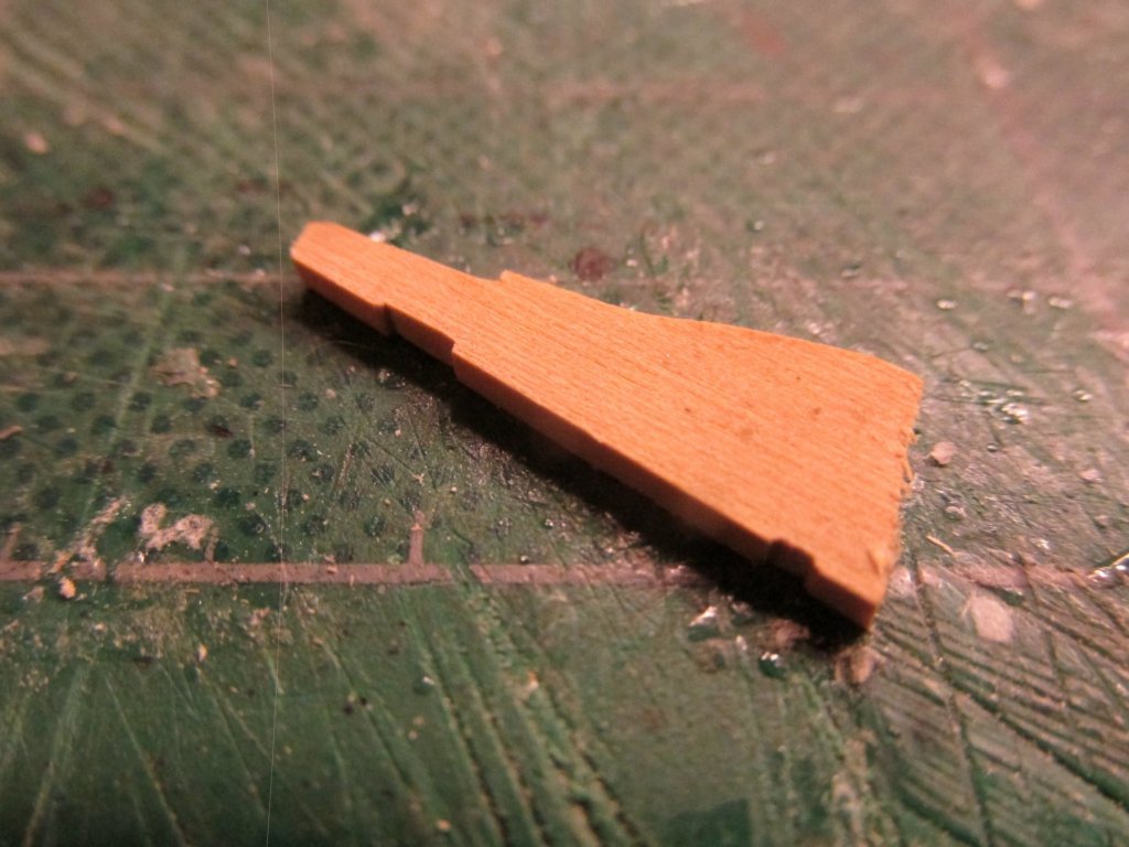
Pinnace Rudder
The last major piece of the pinnace is the rudder. As in my previous part fabrications, I made a template from the US Navy plans and cut out the part from some boxwood stock. So far everything was going smooth…too smooth as it turned out. To my surprise, when I placed the newly cutout rudder part next to the stern of the pinnace, something was wrong…very wrong. The part matched exactly the shape and size in the plans as all my other parts had done except in this case IT WAS TOO SMALL for the boat. What was going on?
The length of the boat was correct, so was the width, but not the height. I never measured the height of the hull once it was carved. I never thought to check that dimension since the hull was formed using the pre-cut pieces that made up the bread and butter sandwich method construction. Subconsciously I just assumed the carved hull was correct for outside dimensions. For some reason(s), either accumulative measuring errors, I didn’t remove enough material during the carving process, or whatever, the hull was too tall. I was not about to shelve this little model and start over.
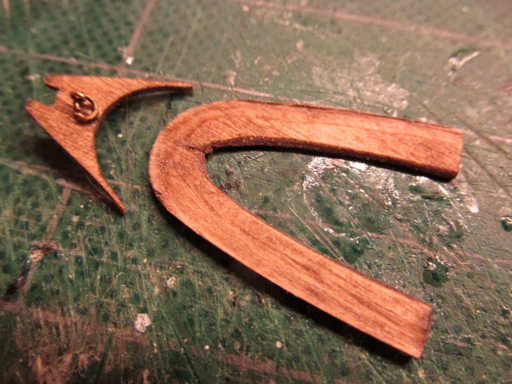
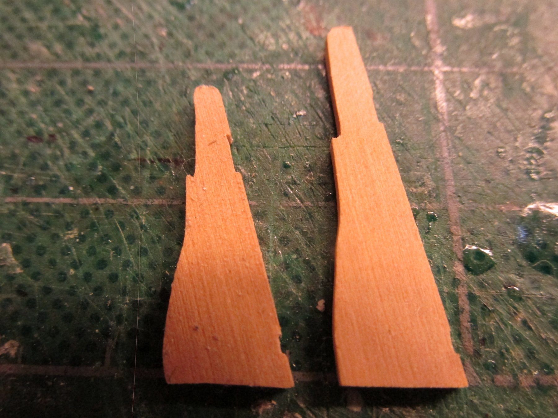
To salvage the model, I decided to just go with it and only I, God, and the readers of this log would know. I got on the computer, brought up the image of the US Nay plan of pinnace (reduced to scale) and stretched the image vertically to reflect the actual build height. That image was printed, a new template was made, and a new part made. In the photo below you can see the difference.

- Geoff Matson, Tigersteve and MEDDO
-
3
-
Beautiful looking model. I noticed that you haven't documented the building of the ship's boat. Have you made it yet?
You might want to think about installing it soon before you have too many lines interfering with a clean installation.
Jon
- EJ_L, Martin W, Tigersteve and 1 other
-
4
-
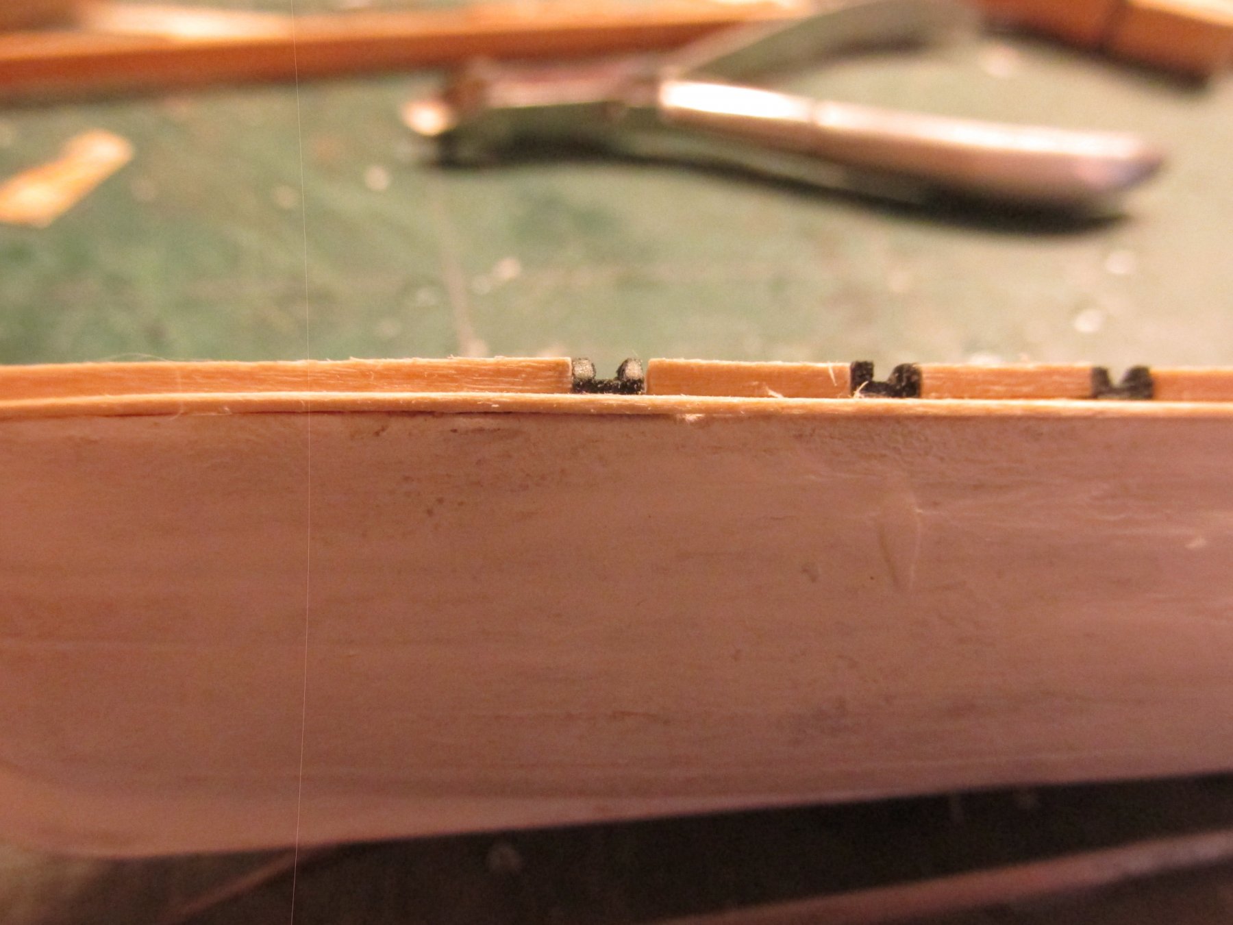
CA glue was used to adhere the strip to the hull working my way from the bow to the transom for each side. Then the transom fender piece was added.

-
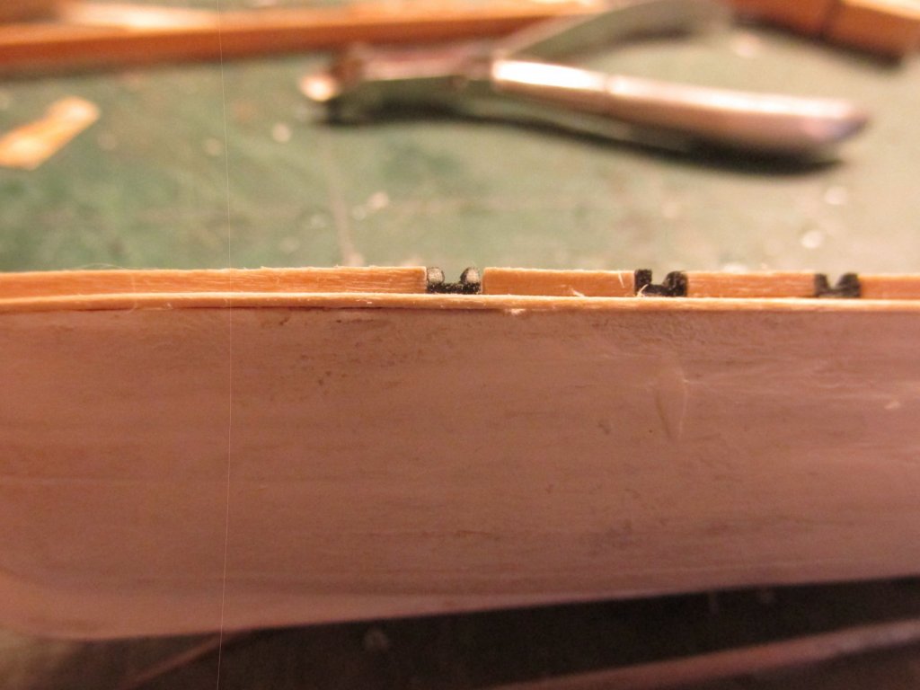
Pinnace Fender
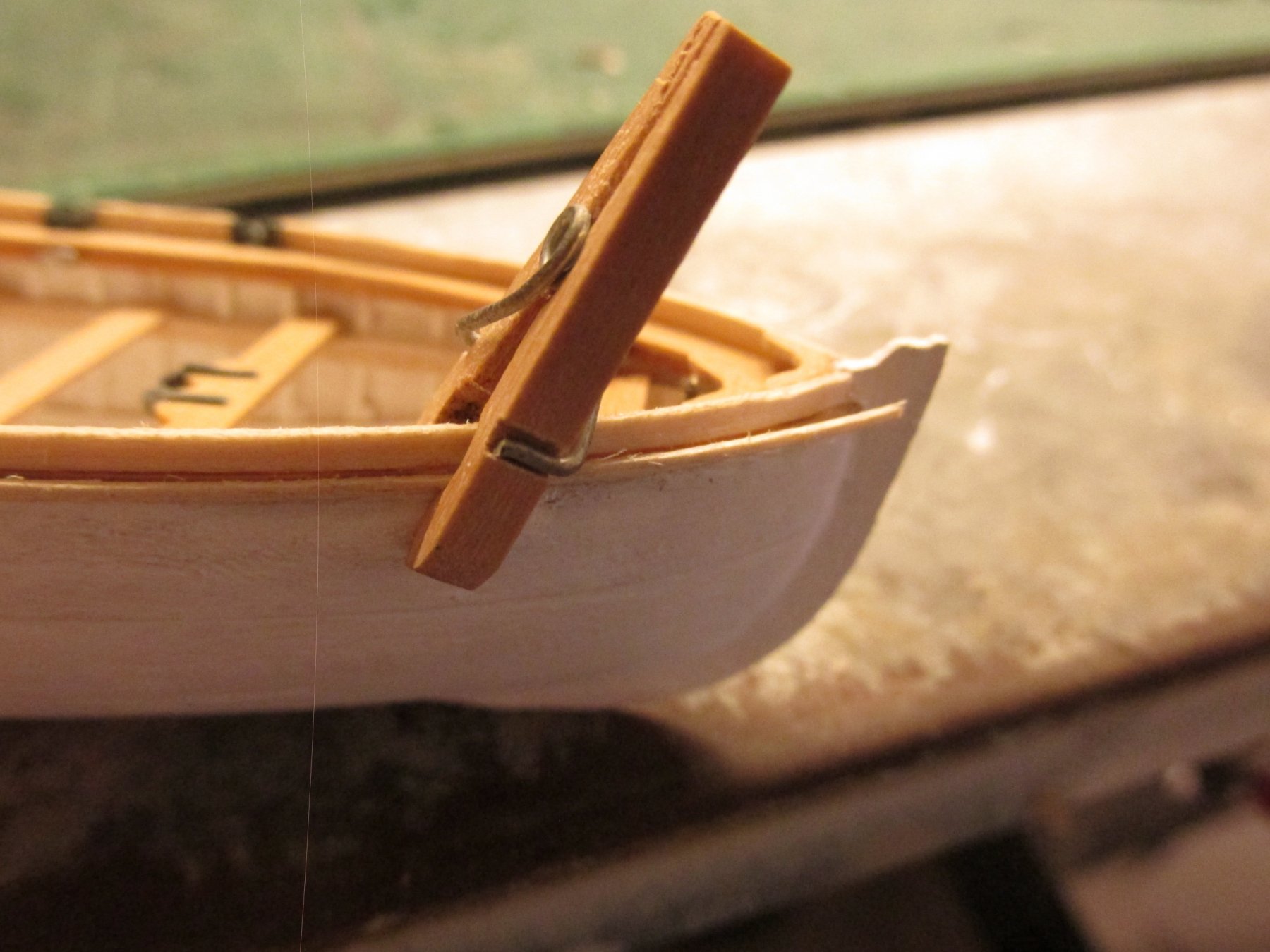
The last thing to install on the hull (excluding the rudder) was the half round fender. Per the US Navy plans, the fender 2½” x 1¼”. This translated to 1/32” x 1/64” at scale which matched the kit’s instructions. Now that is one fragile strip of wood. I chose to use 1/32” x 1/32” because wanted the extra strength as I pulled it through a scraper to create the half-round profile. When I was done, I needed my magnifying headset to actual see the roundness and to be sure I was gluing the proper side to the hull. In other words, nobody but me would know I had even bothered to shape the fender
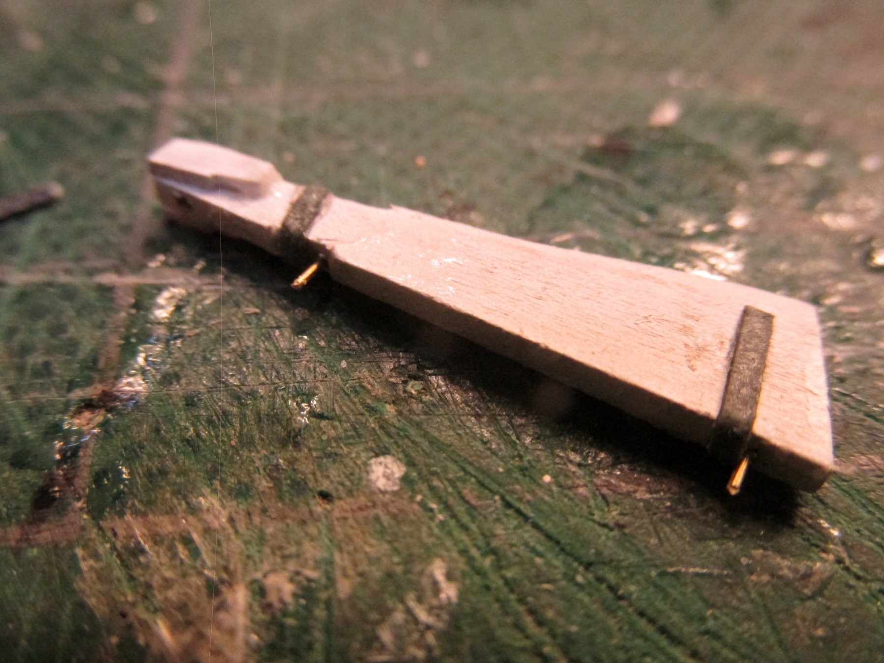
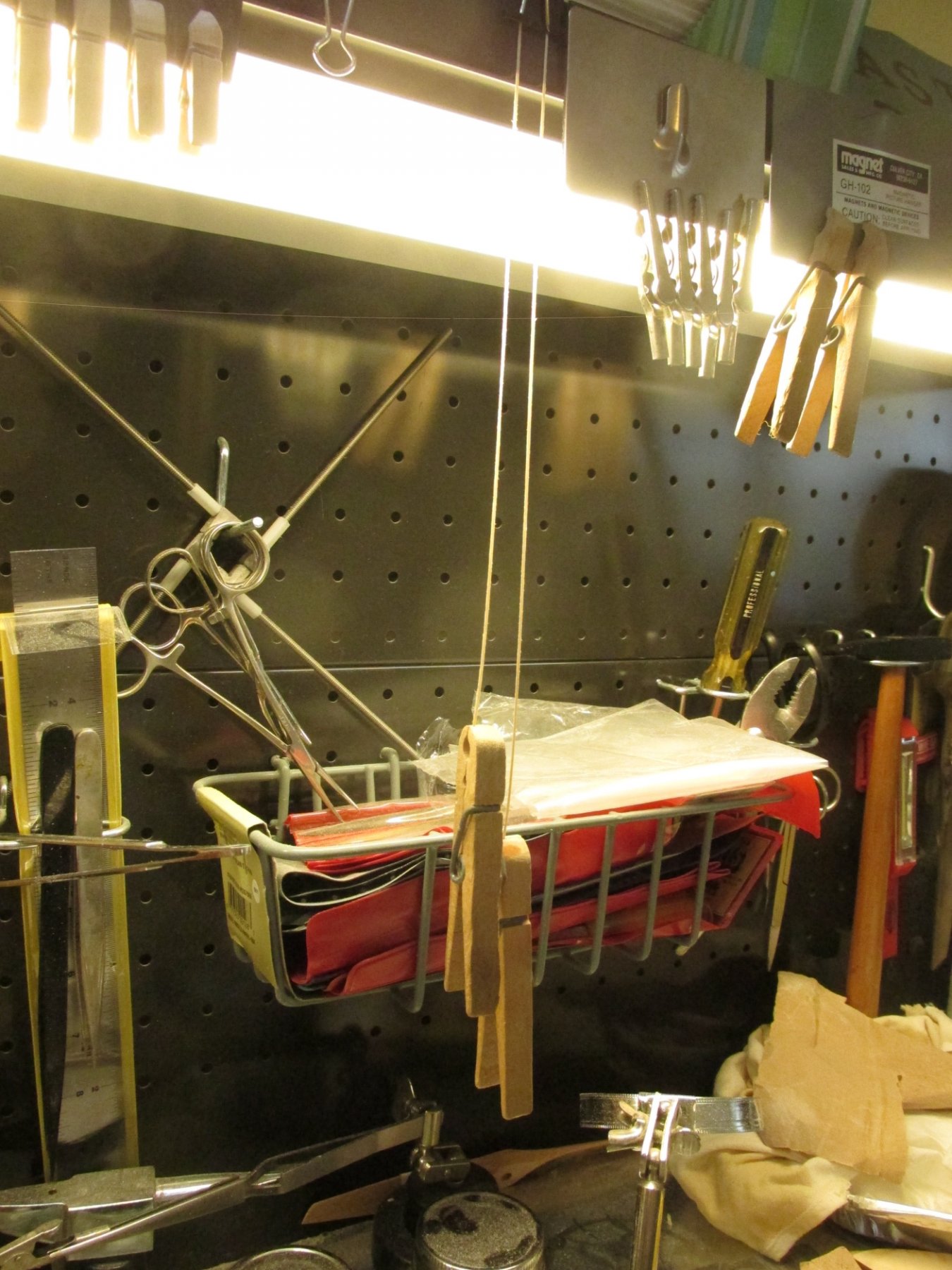
Initially when I was pulling the strips through the scraper, the fine strip would curl 90-degrees towards the scraped side, opposite of what I would have liked. Dipping my fingers in water and pulling the strips through my fingers removed the curl as the water seeped into the wood. To ensure the strips didn’t re-curl as they dried, I hung them with a clothes pin as a weight to keep them straight.

-


USS Constitution by JSGerson - Model Shipways Kit No. MS2040
in - Kit build logs for subjects built from 1751 - 1800
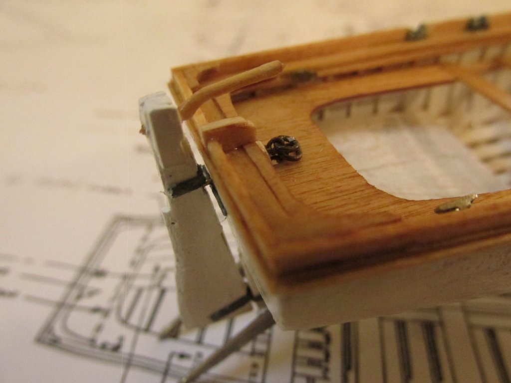
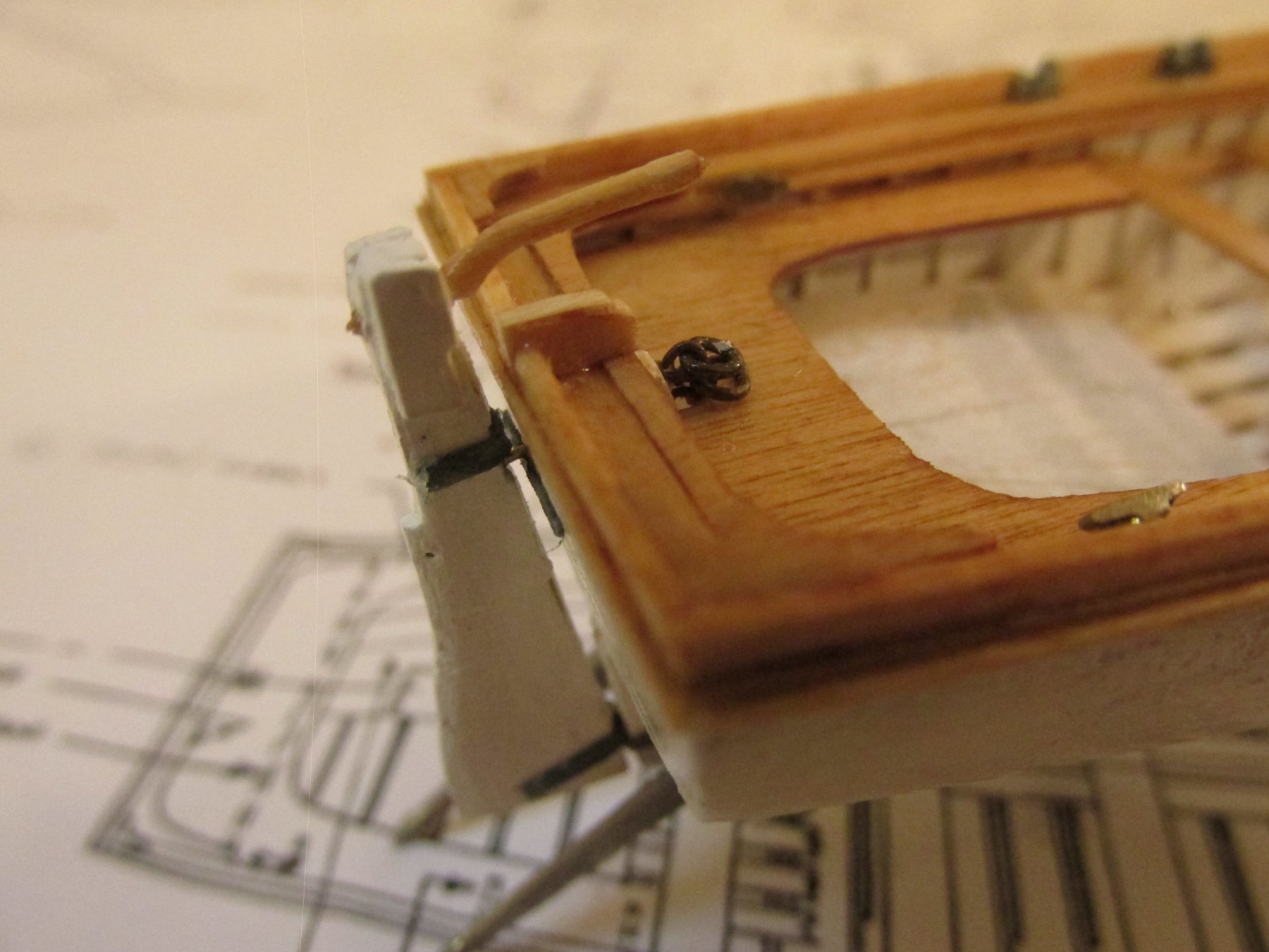
Posted
The bench is supported from below with pilasters. I made mine from bamboo skewers that are available at any grocery store. Using a Byrnes draw place, I made a 1/32” diameter “toothpick” and cut seven, 7/32” segments. Three for each side, and one for the apex. These were a bit long, but it gave me room to adjust the lengths to make them fit under the bench. The actual pilasters have a fancy curvy profile to them, so I filed the centers to create a subtle “hourglass” shape. The pilasters were then stained and glued to place.