


JSGerson
-
Posts
2,171 -
Joined
-
Last visited
Content Type
Profiles
Forums
Gallery
Events
Posts posted by JSGerson
-
-
Just being picky, but I assume you drilled a 0.132" hole in the twisted end and not the 1.32" as indicated...just saying. 8-)
Jonathan
P.S. Beautiful workmanship and documentation of it.
- GLakie, Canute and CaptainSteve
-
 3
3
-
David - I chose the Mamoli kit because the practicum was based on it, although you can use the practicum with MS kit for the most part. I had no idea what MS kit looked like at that time. I finally purchased the MS plans on one of MS's many sales and got it cheap and downloaded their building instructions from their website.
The structure of the two sets of plans are completely different. I like the Mamoli plans because it gives more detail diagrams, but I have to look at multiple diagrams to get a complete picture of what I have to do. The instructions are written on the plans and for me difficult to read - I wear strong tri-focals using an eye loupe as I am blind as a bat without these optics. Being a newbe, this has been a problem for me especially the rigging. There are numerous places where I could have done things sooner, off the model, and easier had I understood and realized it.
The MS plans give a more complete picture but less detailed breakdown diagrams and no sense of order of construction with individual instructions all over the place on the plans and instruction booklet. So I use both now, but as you have surely read on my log, there are differences in the details. Then I have Harold Hahn's plans (which Bob's practicum is based on) and through another builder, the plans for the Smithsonian model. Again some differences in detail in each.
If you can, get the wood supplement described in the practicum. I got mine at Hobby Mills before Jeff Hayes retired from the business. Jason Clark's Crown Timberyard has picked up the slack and provides a very nice product. If he doesn't have the list of replacement wood and sizes, I can provide that based on the invoice of what I got.
DocBlake - Thanks for the like. I can understand why you put your Rattler aside, that transom can be very frustrating if something goes wrong especially if you don't know what it was that went wrong. When you get the courage to go at it again, I'll be watching.
Jonathan
- CaptainSteve, usedtosail and Martin W
-
3
-
David, if I might Interject into your conversation, I too am a fan of Robert Hunt's practicums. They have a lot of useful stuff and I could not have built, let alone started building my Rattlesnake (my first square rigger build) without it. Just be aware that Bob is human and not perfect (he has a lot of idiosyncrasies that others might attest to) and therefore his practicums (at least the Rattlesnake's) have errors which I have pointed out in my log. Some of his dimensions were wrong as well as some of his building sequences were not fully thought out (my opinion). Double check everything and get second opinions on how to accomplish things from other build logs. He does state in the Rattlesnake practicum that there maybe better ways of doing things. I look forward to following your build log as the Conny is my planned second build and using his practicum.
-
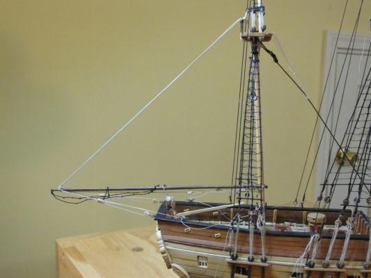
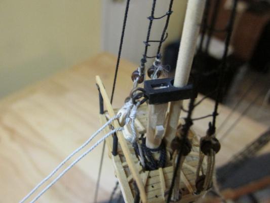
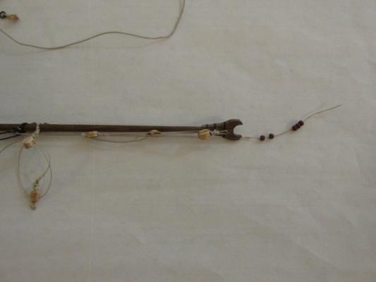
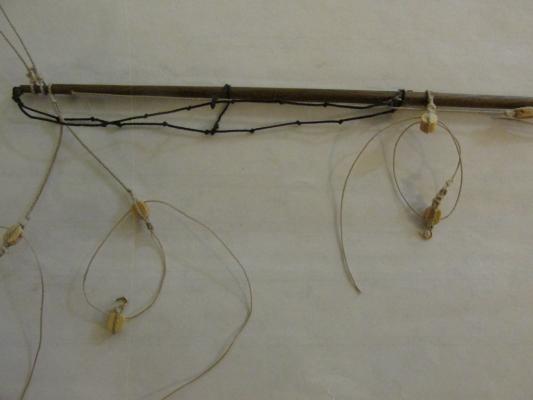
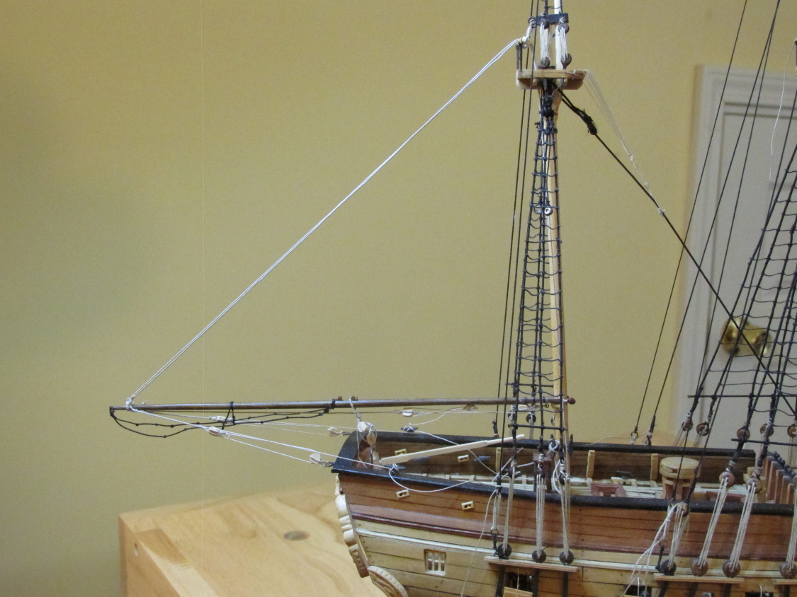
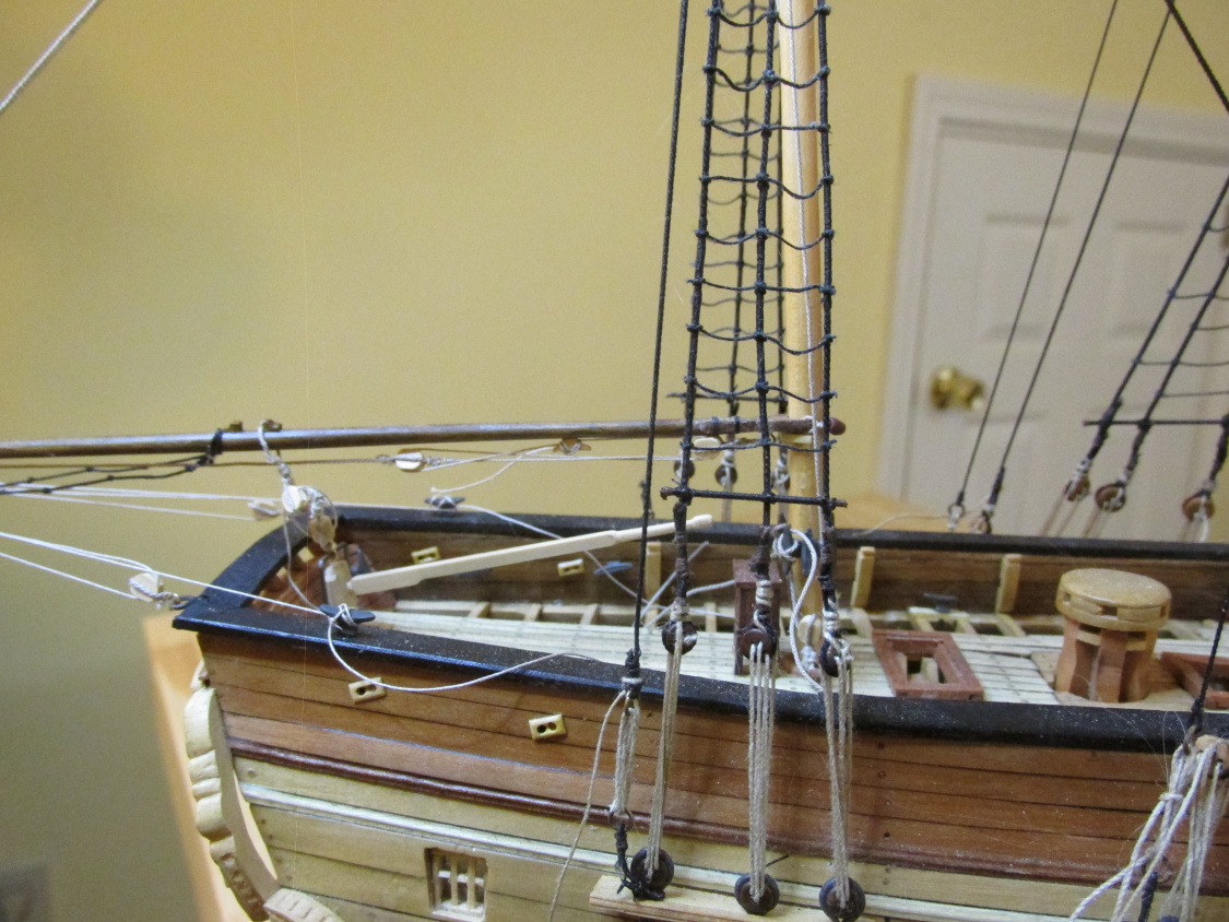
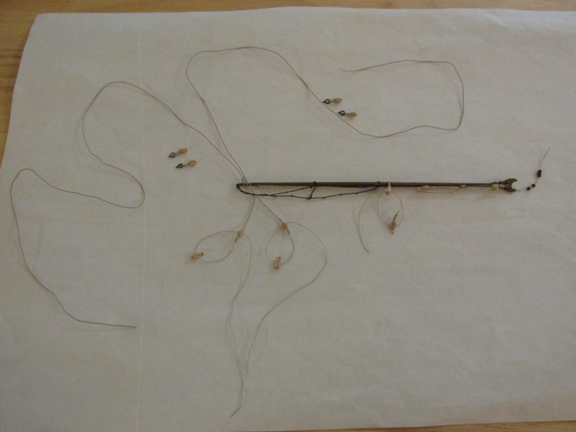
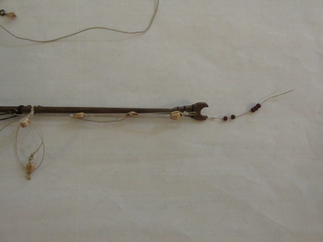
Installing the Mizzen Boom
The first order of business was rigging the parral. Before installation, the parral line was attached to one of the boom’s jaws with a pseudo eye splice through the pre drilled hole in the jaw, and five beads were threaded on. The boom was positioned and the line was threaded through the hole in the other jaw and tied with a simple knot and glued. Now it was just a matter of hooking everything up and adding the two blocks to the pre drilled holes on the mast cap and a block each to the pre-drilled holes on the deck on either side of the mast. Sounds simple, of course I’m describing all the failed attempts due to dropped and lost hooks, failed block stroppings, wrong length of line used, etc. You know the drill.
-
There is no consensus that I could find that states which is the best order to add the yards and booms so I decided to work again from the stern forward, bottom to top, one level at a time. In other words, add the mizzen booms, then the lowest yards working forward. This would be followed by the midlevel yards aft to forward and finally the top masts aft to forward. Whether this is the optimum way to do this or not, I don’t know. We’ll see.
Mizzen Boom
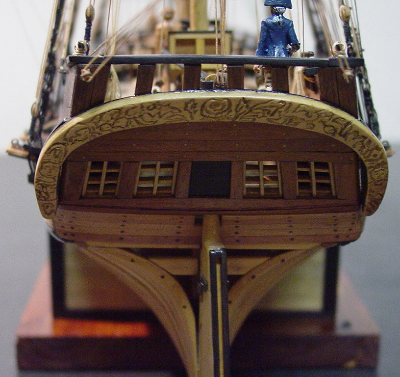
Thus the first order of business was to rig the mizzen boom. There was more stuff on this piece than I realized. It required 12 blocks; some were double blocks and others required hooks. Speaking of blocks with hooks, the Mamoli plans show that the Guy Pendant goes to a tied block on the taffrail (the railing above the transom) eyebolt. The MS drawing indicates that the block is hooked to the eyebolt. I couldn’t use Antscherl’s book as a guide because the model he was describing only had a gaff, no boom. However Petersson’s “Rigging Period Ship Models” did show that blocks attached to the hull were hooked. So, I decided to go with the hooked block because I thought that is what was probable used, plus I thought it looked better (what do I know?).
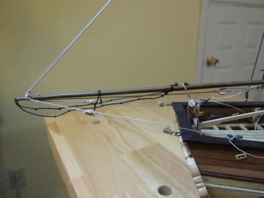
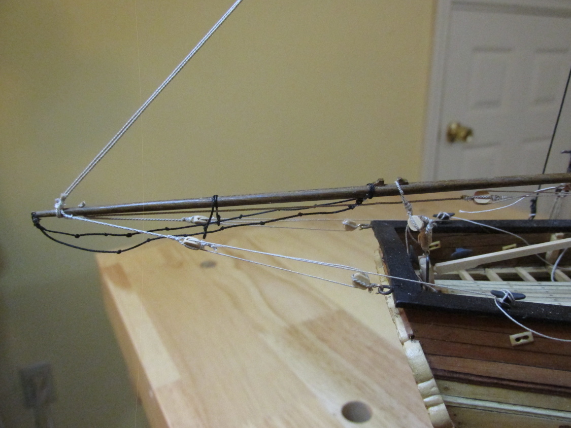
Mizzen Boom Parral
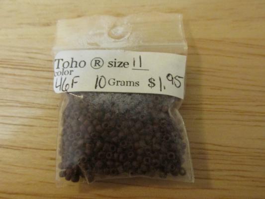
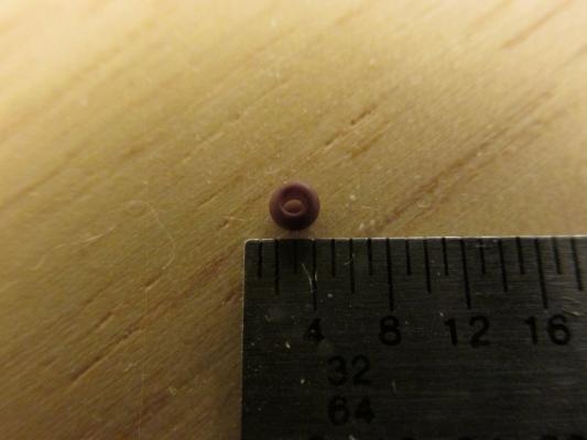
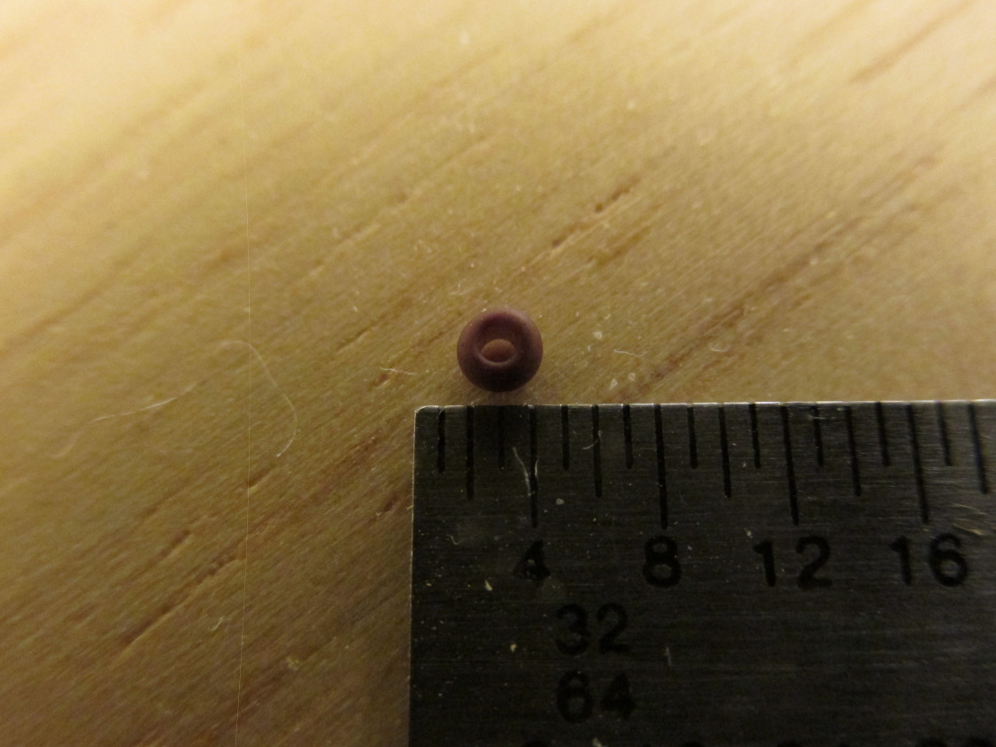
Another difference between the plans is the boom and gaff parrals. Mamoli just uses a loop of rope while MS shows a single rope with parrals and no ribs. Checking my sources, James Lees’ “The Masting and Rigging of English Ships of War 1625 – 1860” confirmed that no parral ribs were used for the boom and gaff but made no mention (that I could find) of using just rope. Maybe no parrals were used on smaller ships, I don’t know, so again I chose to follow MS. Lees stated that these trucks were about 3/8 the width of the boom. Since the boom and gaff were 0.10” and 0.09” at their widest point meant their trucks were 0.075 and 0.034” respectfully. I purchased a small bag of beads from a local bead shop. I got the smallest size they had. The bag was marked “size 11” which meant nothing to me. I measured them when I got home – 0.08”. These guys are tiny and I don’t think I could handle, let alone thread, anything smaller, so that’s what I used. One other thing, real trucks tend to be as wide if not wider than their diameter; these beads are a bit narrower. That raised the next question, what size is the rope used to thread the trucks? The only places where I found which described the parral rope size was Antscherl who used 2” (circumference) line (0.01” mini-rope) for his gaff, and the Smithsonian’s plans which showed 1½“ line (0.007”). Since I have both the kit’s 0.009” rope and Syren’s 0.008” rope, I had a choice, not that anyone could see the difference; I chose Syren, it looks better.
- CaptainSteve, Geoff Matson, Martin W and 1 other
-
4
-
Wonderful! I glad you decided to at least making the attempt to create your own decorations. Based on your carved snake, it should look great. Believe me, you will feel a whole better about the model than if you had used the cast metal part. I look forward to following the process.
Jonathan
-
Sorry Mundie, I know nothing about coppering so I can't help you there. And not to be adding to your coppering burdens but I've following xKen on his build of the Conny. He appears to be at the same place as you in your build and he ran into a problem that might affect you as well. He ran out of copper tape. You might want to look at his build if you haven't already, He may also have an idea on how to solve your present sticky problem since this is not his first coppering model..
Jonathan
-
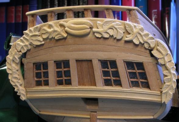
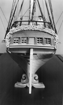
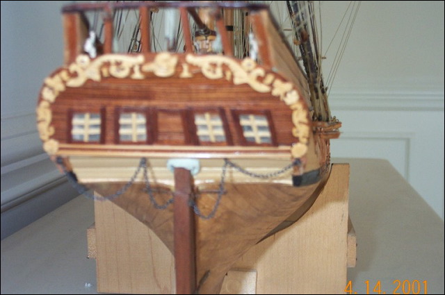
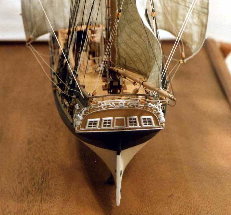
Here are four build decorations I've found on this site and the web plus the Harold Hahn (B&W) version. Each one is different; there is no correct one. Some harder/easier than others. Give it a shot, you got nothing to lose, and if you like what you made, you'll feel better that you did.
I copied Robert Hunt's who copied Harold Hahn. Mine is a far cry from the original
Note: the images are from Jim McCurdy, Pasi Ahopelto, Raul Guzman, and Paul Bishop in that order


-
Oh, don't dread! This is fun remember? When I started my decorations, I was looking forward to it even though I've never done anything like it before. It was a fun challenge. If you were to look at what I was trying to copy (Robert Hunt's decorations) and compare those to what I made, you would see the difference between a master and a novice, but since most people won't, I look good! Try making some decorations on scrape wood (or clay if that's your plan) how bad can it be? Look at other builds, no two are alike so you can't be wrong in what you make. I would still like to see you attempt the whole arch. At worst, you use the metal one if you don't like your work.
Jon
-
The bigger problem is that on Hahn plans, there is another piece of decoration behind the supplied metal one. There are also fashion pieces with decoration that need to be created. Since they aren’t supplied, I’m going to have to create/carve them both.I assume you mean the two side pieces that fit in the corner of the transom below the decorative arch. They are going to be a bit tricky. In Robert Hunt's practicum, he chose to use Primo or Sculpey clay more as an example of technique rather than prime choice of method. It enabled him to form the pieces to fit the model easily. Carving was simplified because until the clay dried he could work it till he got right. Looking at his results, there was a slight change in color and texture due to the change in material I didn't like and since my model wasn't being painted, I couldn't cover that up. I decided to continue using boxwood and carve them like I did the decorative arch.
What ever method you use, you are going to have to deal with a compound curve as the pieces curve in and back under the transom. It took me numerous attempts to get it right and don't forget, you have to make each one an exact mirror images of each other; and then you will have to form or carve the decorations. Good luck
Note: The Mamoli kit does provide those decorative pieces.
Jonathan
-
Be aware that the "new" copper you receive will probable not match the hue of the installed copper...at least initially. This is probable due to the difference in time it was exposed to the air. Hopefully over time, the two batches should even out.
Jonathan
-
In the picture of the stern area the small wheel was carefully used on the hull once the plates were cut to fit in place.I thought it was an optical illusion but your comment about using the ponce wheel directly on the hull seems to confirm it - your "rivets" are inverted. The models I've seen in other build logs seem to show raised rivets like those on the bulwarks. I like yours better. Looking at the actual ship, where the "rivets" are applied, the copper seems to be pulled in towards the hull creating a dimple, which is what one would expect Nice work!
Jonathan
-
Thanks for dropping by Ken (xKen). Buying a milling machine will remain on my wish list for now. As I have mentioned, all of the woodwork on this build is complete and I won't start the Frigate Constitution until I've completed my Rattlesnake - I don't need any more diversions to its completion, I go slow enough. That gives me time to figure out exactly what I need vs what I want; the two, contrary to popular belief, are not necessarily the same.
Jonathan
- Martin W, fish and CaptainSteve
-
3
-
-
Thanks for the reply. Yes, they are the same ones I have. I always ask because one never knows if there is some new/wonderful source of tools/gizmos/gadgets/jigs that they haven't explored yet.
Jonathan
- CaptainSteve, GLakie and Canute
-
3
-
Blue Ensign did something very similar on his Pegasus stern carvings starting at posting 1372. Now if you can keep the technique a secret, you will really impress your friends!
-
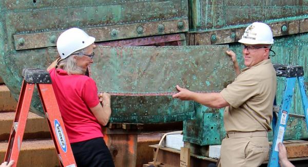
Ken, I've been quietly watching your build log as I plan to build my own model as soon as I finish my present project, the Rattlesnake (in the next decade or so at the rate I build). I have never copper plated before as the Rattlesnake is my first real build and doesn't require it. I'm a little apprehensive when the time comes. I was curious as to what size ponce wheels you are using and where did you get them.
Looking at pictures of the plating process on the actual ship I noticed that, at least in the close-up photo below (which was taken in the rudder area), there are tight border rivets like you've duplicated and 5 rows of wider spaced rivets in the body of the plate. I think you were smart to choose 3 rows for the model because any more at that scale I believe might have ruined the effect.
Thanks for posting large sharp images which makes it very easy to understand and follow your progress.
Jonathan
-
Ken - Well it's either there or where my socks disappear to 8-)
- CaptainSteve and Martin W
-
2
-
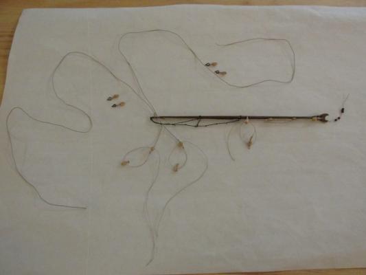
Finally, a coat of Wipe-On-Poly was applied to the completed yards and booms. On a final point, a milestone has been reached – All of the wood working on this model is now complete (as far as I know). All that is left is the remaining rigging which continues with the yards, off the model.
- Ryland Craze, Jack12477, Martin W and 7 others
-
10
-
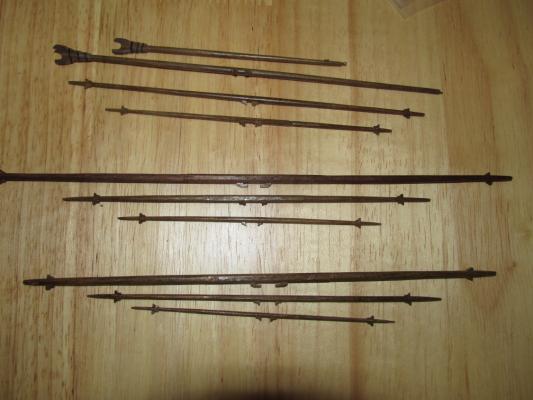
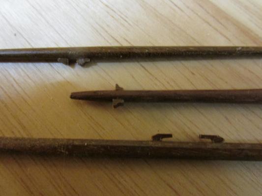
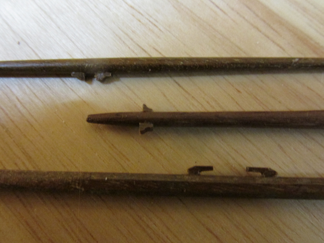
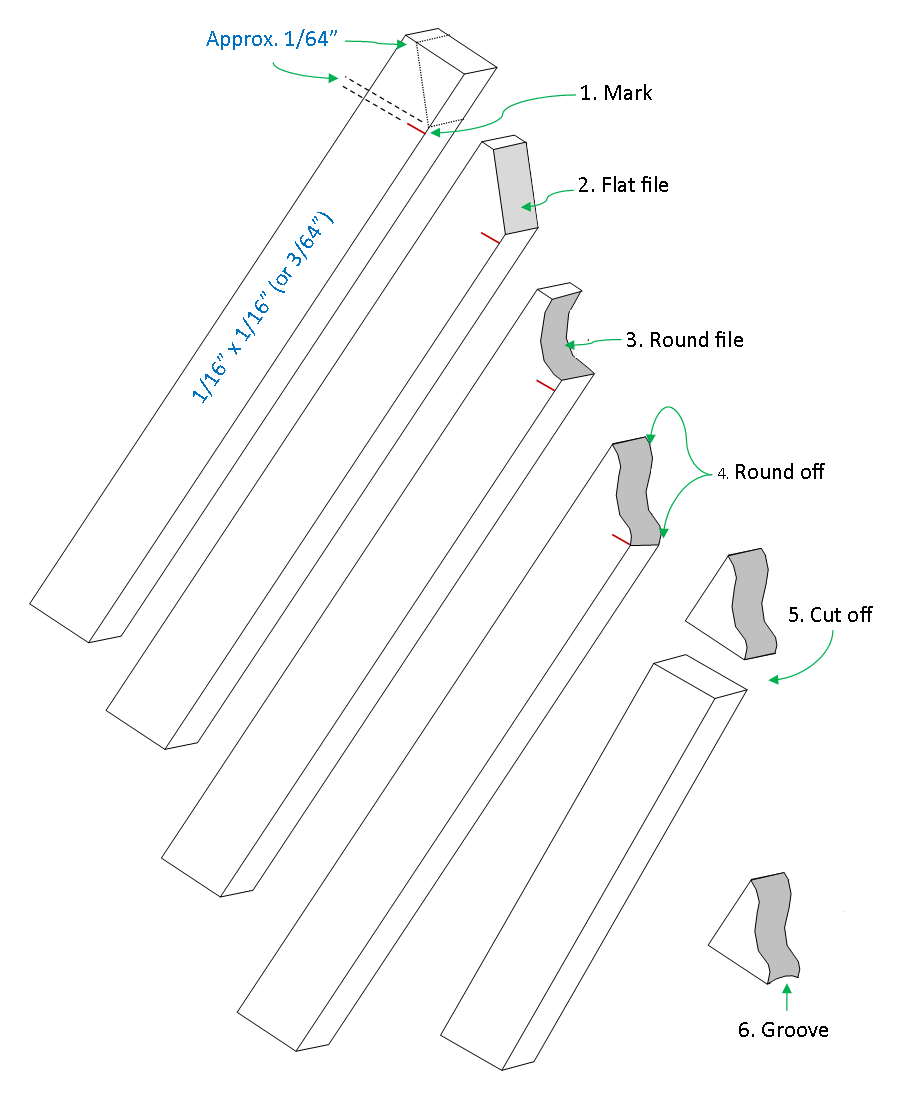
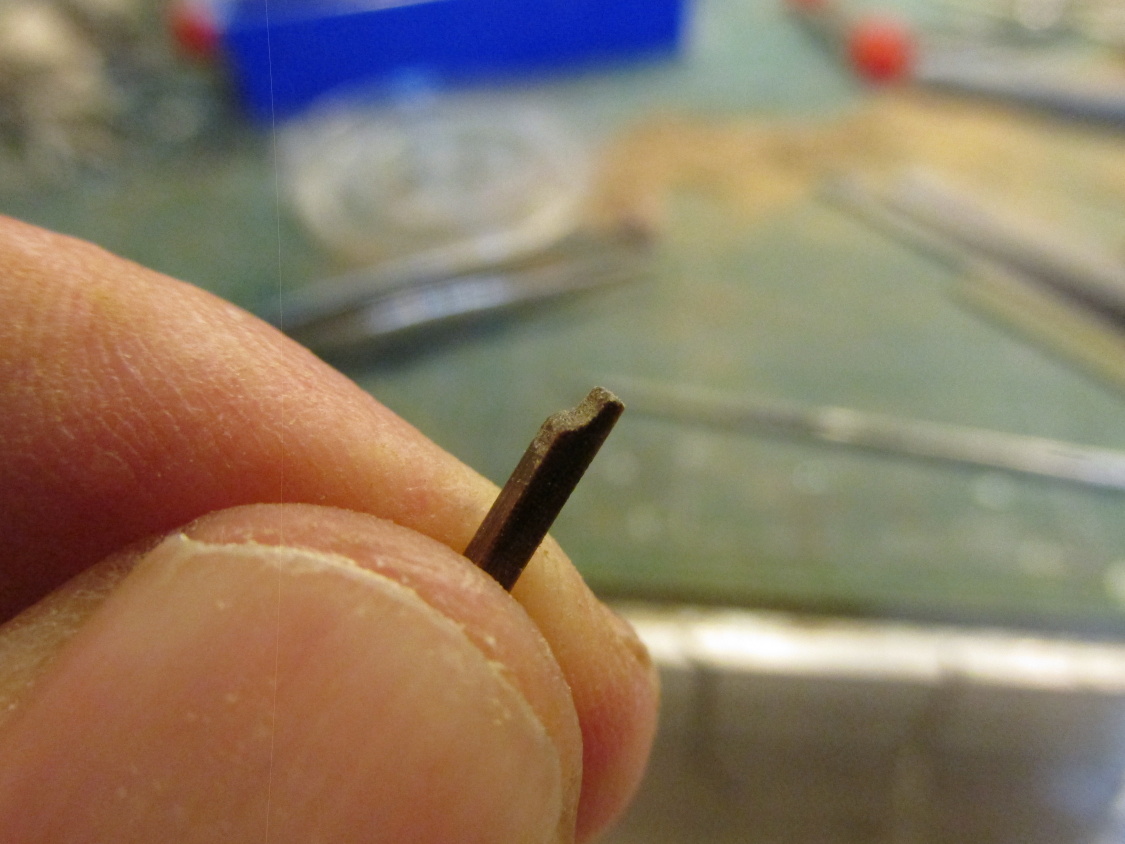
The 42 chocks were next. They were made in 6 steps per chock. Yes, this was tedious and exacting work although that actual process didn’t eat up too much – 2 to 3 minutes per chock or 1½ - 2 hrs total once you got into the rhythm. I usually stopped after 6 chocks to apply them to the yard to break the monotony. Using white glue, they were applied to the appropriate positions on the various yards.
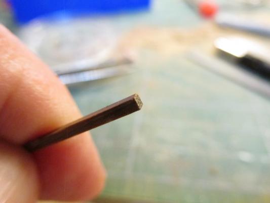
- Measure 3/32” from the end of a 1/16” square piece of stock walnut and make a pencil mark
- File a corner off leaving about 1/64” (eyeballed) from the adjacent corner and the pencil mark with a flat file
- File the resulting surface to get an inward curve with a round face file
- Round off the two corners of the inward curve to the 1/64” faces
- Cut the chock off from the stock at the pencil mark using a miter box. From experience, I have found that using a knife does not always produce a square cut.
- File a groove on the bottom of the chuck so it will sit comfortable on the round surface of the yard or leave flat when placing it on flat surfaces of the yard
Note: for some of the smaller diameter yards, 1/16” x 3/64” stock walnut was used
PSA: If you every drop a chock onto a messy work bench (like mine) or on the floor and you can’t find it in a few minutes, let it go because it’s gone man, it’s just gone. Make a new one; it’s faster than looking for the lost one.


- Burroak, Ryland Craze, CaptainSteve and 4 others
-
7
-
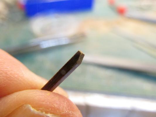
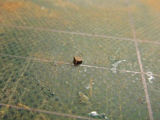
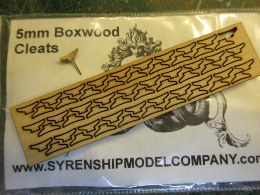
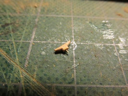
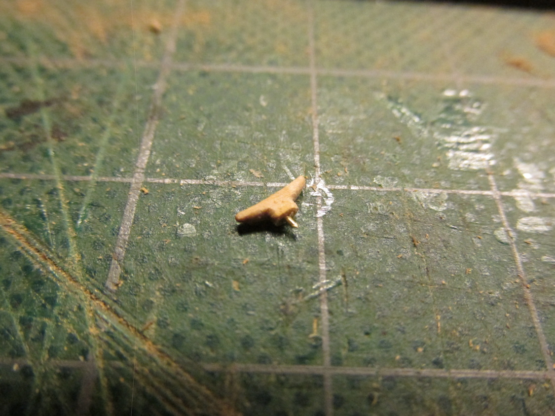
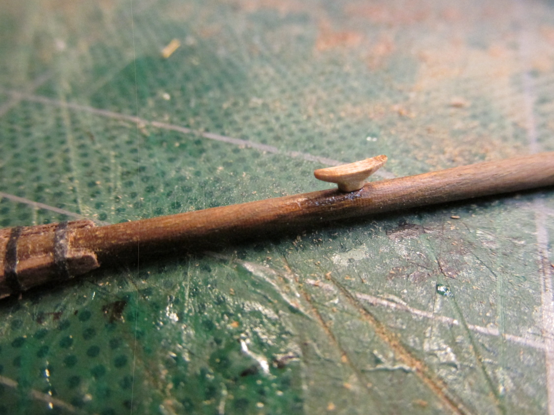
The boom also has a cleat, a sheave, chocks, and a couple of eyebolts that needed to be installed. The gaff just had an eyebolt and cleats. Having made cleats for the Gallows Bits a while back I can tell you they are a pain in the butt and I wasn’t really happy with the way they looked. Chuck Passaro of Syren Ship Model Co. solved that problem with his laser cut cleats blanks. Using the 5mm cleat blank, I added a pin and finished the carving it (smoothing and rounding off the edges). Because this cleat already had a very small gluing surface, and it was going on a curved surface, a mechanical connection was required. After all, a line was to be tied to it and I didn’t want it to be pulled off. BTY, with the pin in place, holding the cleat was made carving it a little easier. Once a hole was positioned and drilled on the underside of the boom, the pin was trimmed to a shorter length and inserted and glued into place.

- CaptainSteve, Burroak, Geoff Matson and 5 others
-
8
-
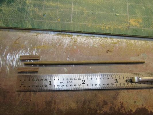
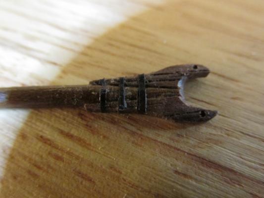
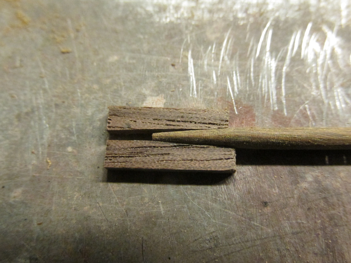
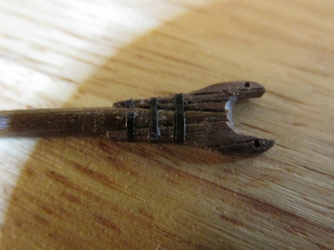
I started with the Boom and Graff because their jaws looked interesting. The Mamoli kit provided cast metal jaws but I had gone this far with fabricating my own parts, I wasn’t about to stop making stuff here. The jaws were constructed from a couple of pieces of walnut tapered slightly to match the ends of the boom/gaff. Once the white glue set overnight to make sure I had a real solid connection, they were carved to match the drawings on Hahn’s plans. The Practicum stated that Mr. Hunt used lead tape for the three straps that went around jaws. I didn’t have any so I used narrow paper strips colored black using a Sharpie pen. Holes were drilled through the tips of the jaws for the parrals which will be constructed and installed a bit later.

-
Thanks for the compliment but it is undeserved. I got it from reading other build logs. Isn't this site wonderful?!
- CaptainSteve and Burroak
-
2
-
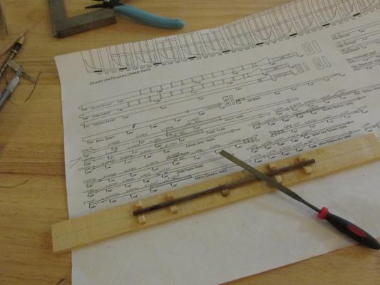
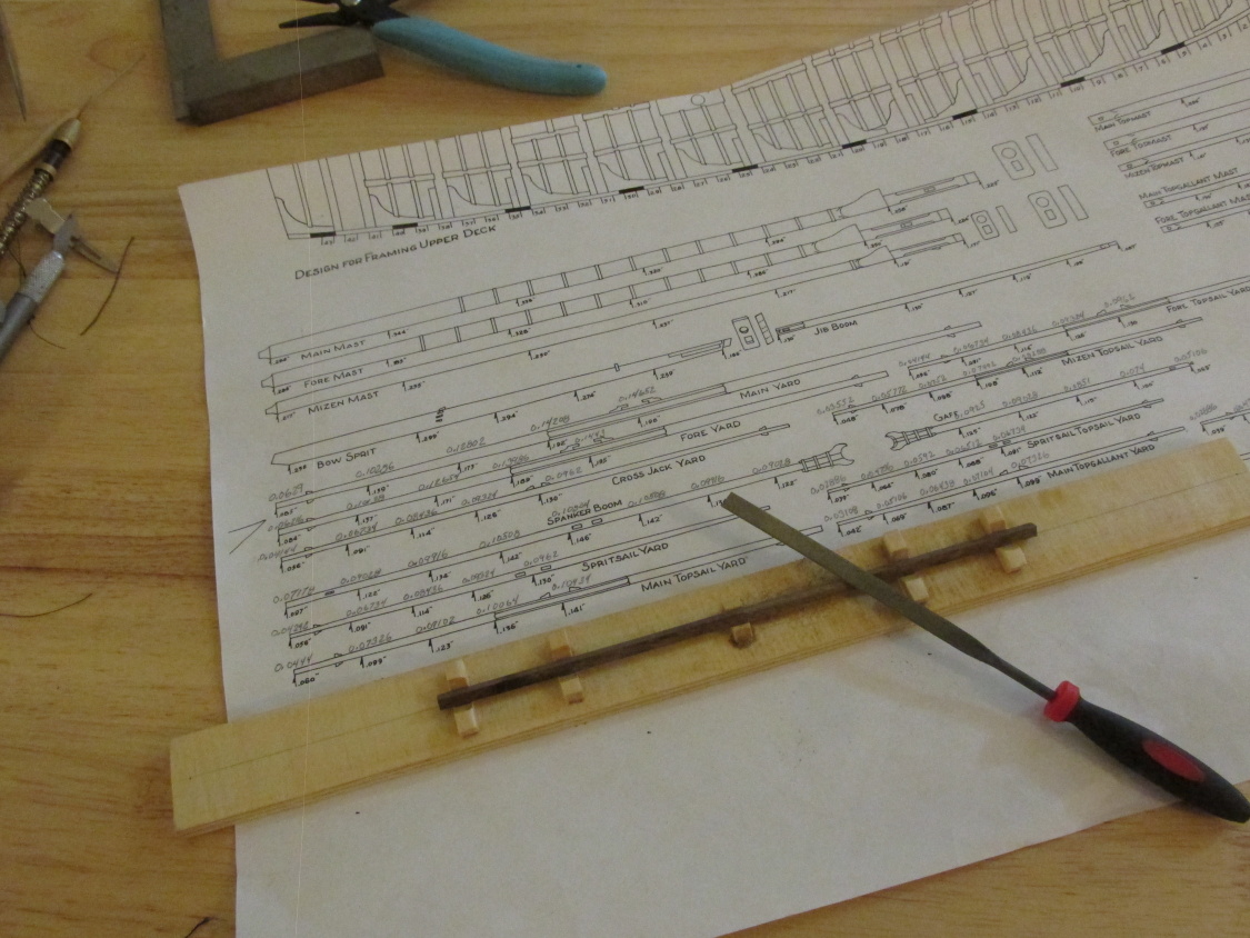
As mentioned earlier, I used the Hahn yard diameter dimensions notated at regular intervals along the length of the yards and booms on his plans. Because Hahn’s plans were drawn at ¼ scale or1:48 the numerical dimensions were reduced by 74% to get them to 3/16 scale or 1:64 of the kit. You might see my hand written notations above Hahn’s in the second image below.
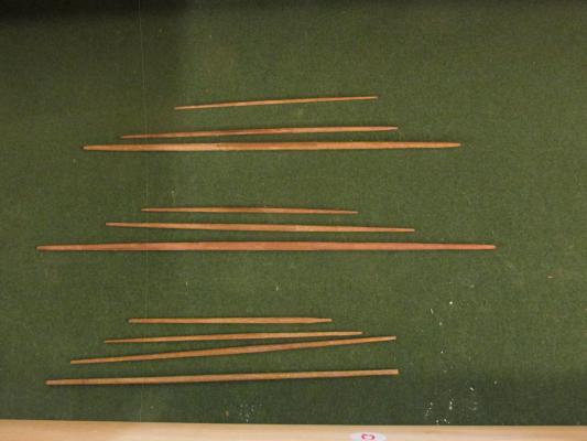
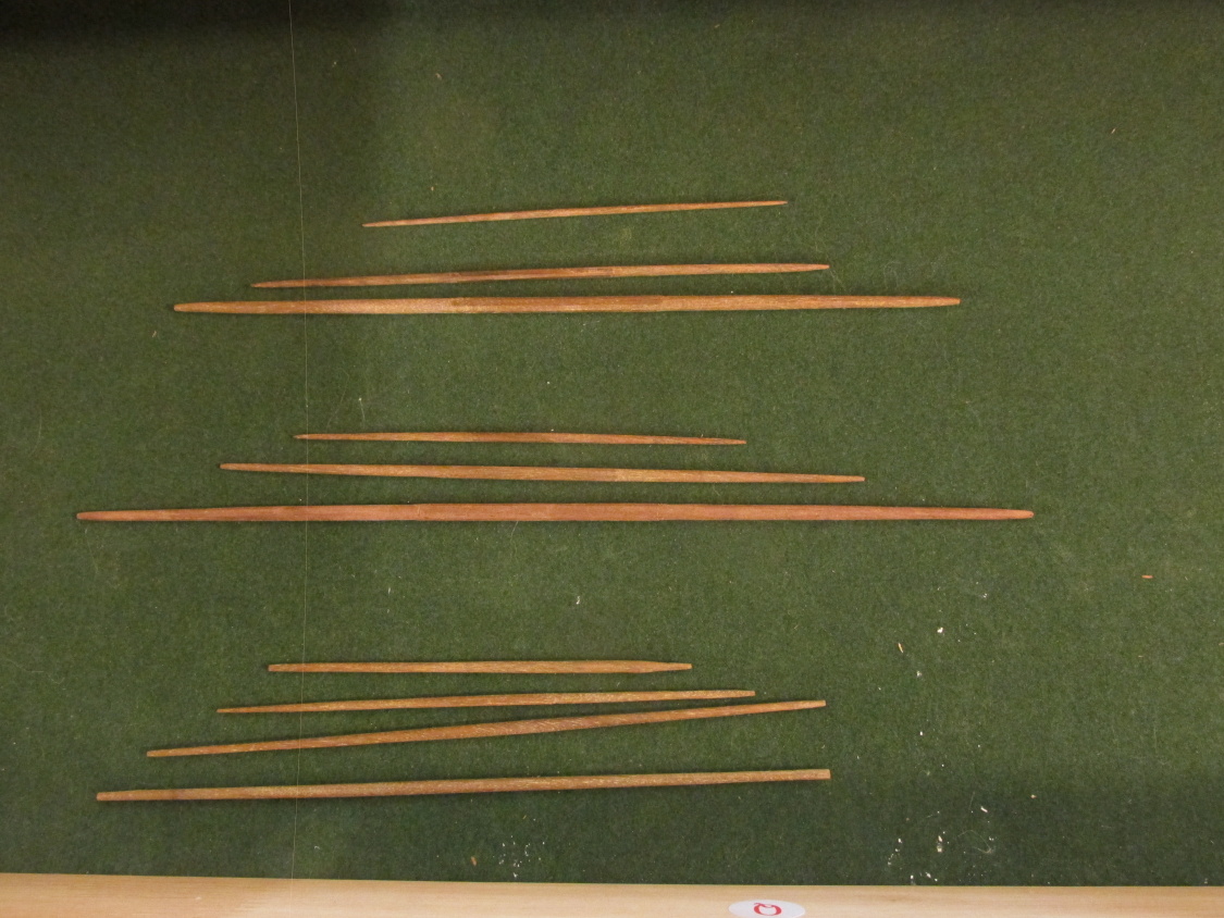
All the yards and booms were made using the simple jig I used before on the masts to hold the square cut pieces so than the corner edges could be trimmed and rounded or left alone as needed. The only tool used was a file. I am not that skilled in using a plane or other bladed tool to trim the wood on these slender and delicate pieces. I can control a file a lot easier because it trims off a lot less material at a time. All the wooded pieces that remain to be constructed and added to the yards and booms are the various chocks, sling cleats, and jaws. The rest is all rigging…as far as I know.
- CaptainSteve, sport29652, GuntherMT and 3 others
-
6


Rattlesnake by KenW - FINISHED - Model Shipways - Scale 1:64 - American Privateer
in - Kit build logs for subjects built from 1751 - 1800
Posted
Great job, I knew you could do it! There, now don't you feel better knowing you did it and didn't use the kit's cast metal part?
Jonathan