Erik Nyren
-
Posts
184 -
Joined
-
Last visited
Content Type
Profiles
Forums
Gallery
Events
Everything posted by Erik Nyren
-
 I figured as much, the pictures does not do the LED:s credid. Right now she´s lit up like a christmas tree so I´m counting on the reduction you speak of. I would not want my Vic to look like the Enterprise Mark; the idea of a lantern although appealing would involve covering up wiring in the masts and rigg. Those details are difficult enough so I´ll probably scrap the idea. Might go for external lights in the display-arrangement instead but thats very far ahead. Plenty of thinking to do until then. Erik
 -
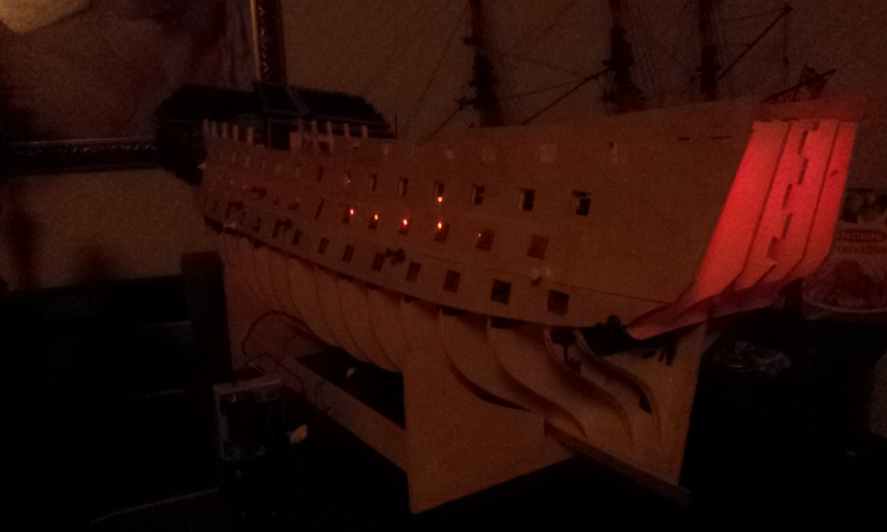
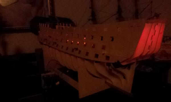
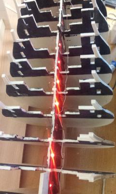
Hello folks It turned out to be next to impossible to take a good picture of the lighting system in the dark but I´m quite happy with the result. Of cource at some angles one can see the LED:s through the gunports but that´s very hard to do something about. Perhaps using a more advanced camera I can get better pictures, Now a question of taste, Should I or should I not install LED lights discreatly on deck to illuminate the rigg? Fellow modelers let me know your thoughts on the matter. Regards Erik

-
Sorry I´m late J Pett. But yes thats about what I did, It would be better to sand back a bit extra of the fist planking at the stern, then less needs to be sanded on the second and you dont want to end up sanding through your second planking (unless you are going to copper the hull). The little book is....well it is....... The words I used to comment the book is not sutible for MSW Please post pictures as you go along so we can follow the progress on the stern a bit closer Regards Erik
-
The fly looks a bit out of scale but other than that amazing detail and precision. Simply beautiful Erik
-
Hello I have had a look at that Bismarck kit aswell but, time, money, space and a few other things stands in my way. Looking forward to a log on the kit. With your skills it will be a masterpiece I´m sure. Best of luck Erik
-
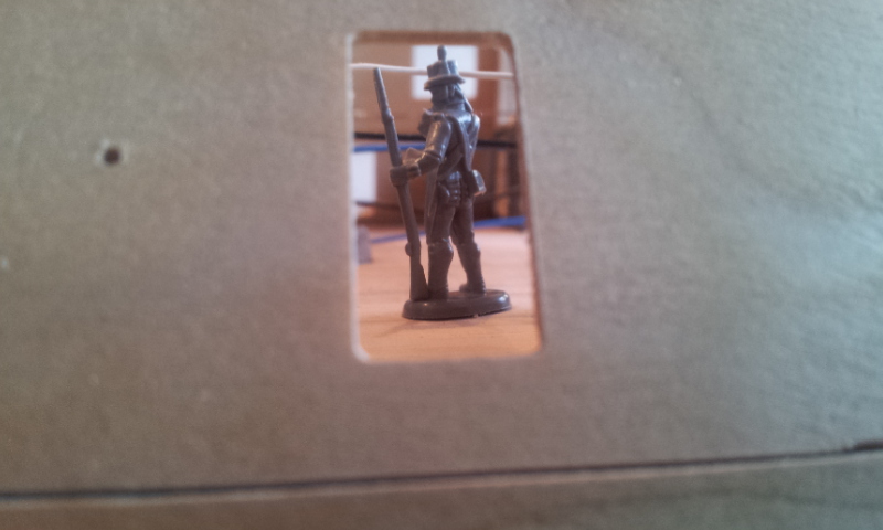
Oh yes it seems the brittish army has started to take an interrest to my build, a little grayish in color but the soldiers will get paid in color after preforming their supervision tasks. Erik

-
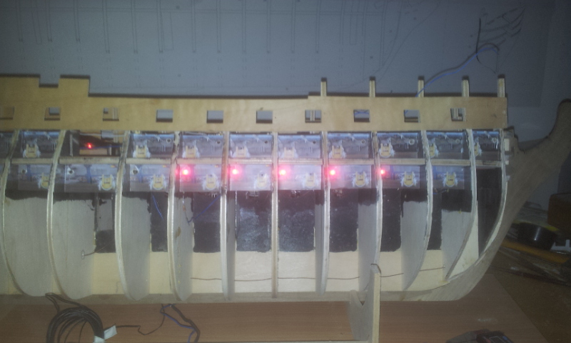
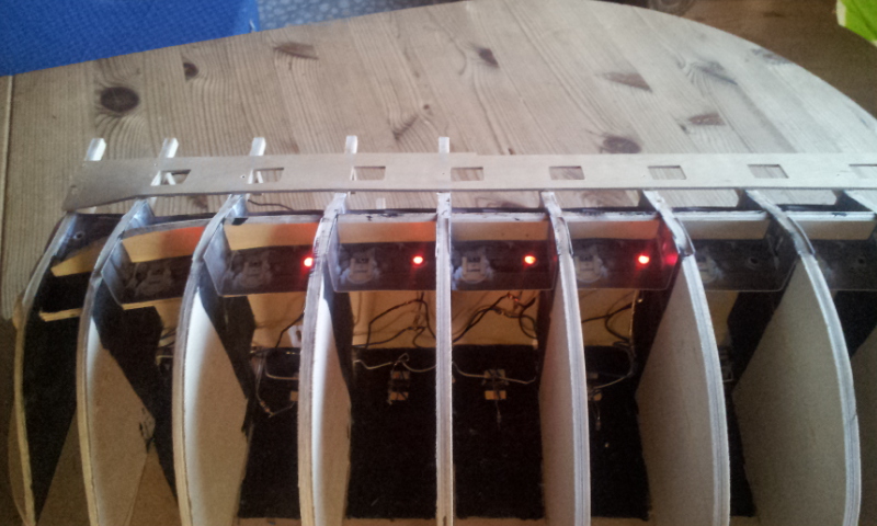
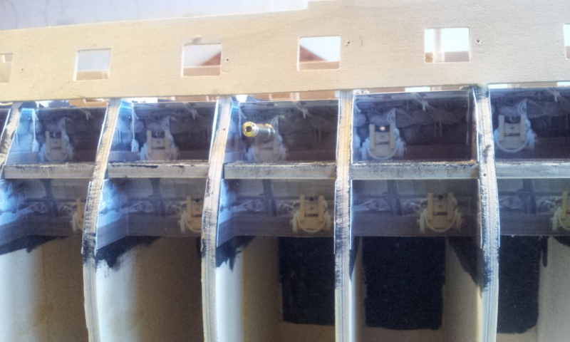
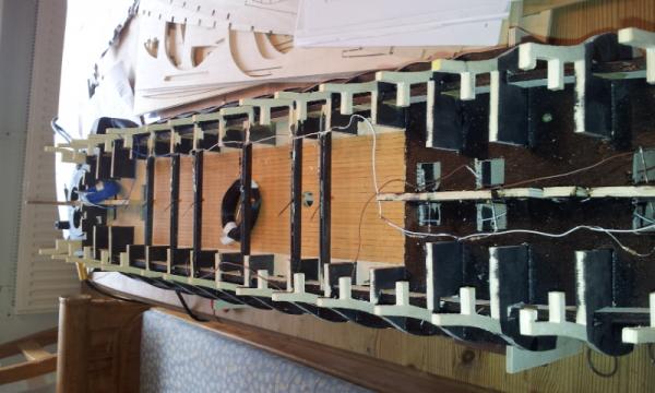
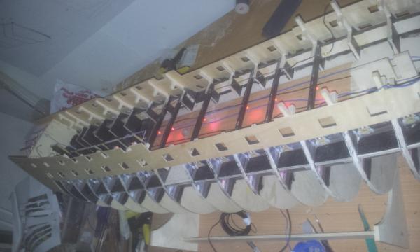
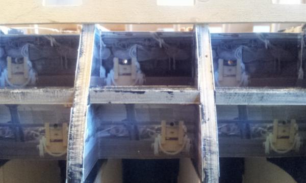
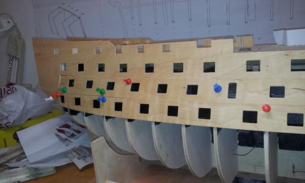
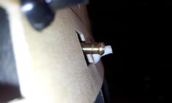
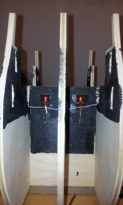
I realised that the lighting from the LED:s centered in the hull will not be suficiant to illuminate the gunports after the pictures had been glued into place. I therefore decided to add one LED to each gunport, hidden from the actual gunprot so it will not be seen. I drilled holes in the false gun support strip to accomodate theese additional LED:S which are wired separately from tha main LED circuit. This enables me to have two different levels of light. One will give a subtile light from the center of the ship where the light will mostly be visible from the gallery. The other will also light up the gunports hopfully in a not to intense way. A few pictures of my work on the LED system, Oh and its run by a pair of 1,5V dry batteries. Regards Erik


-
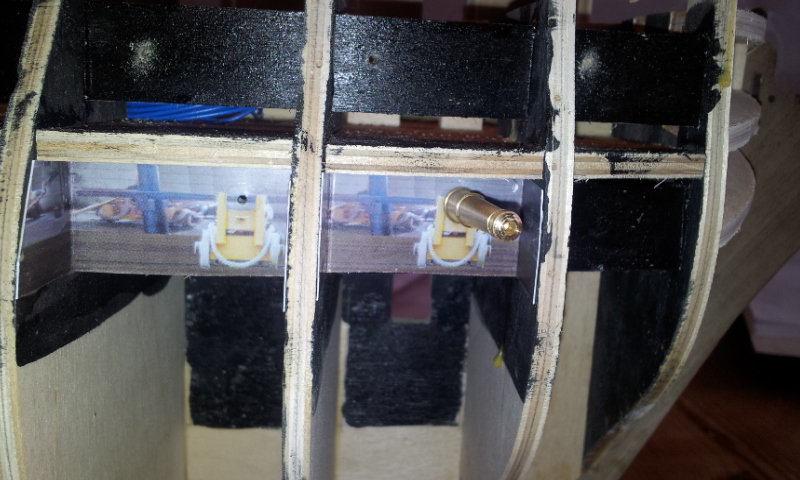
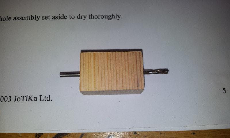
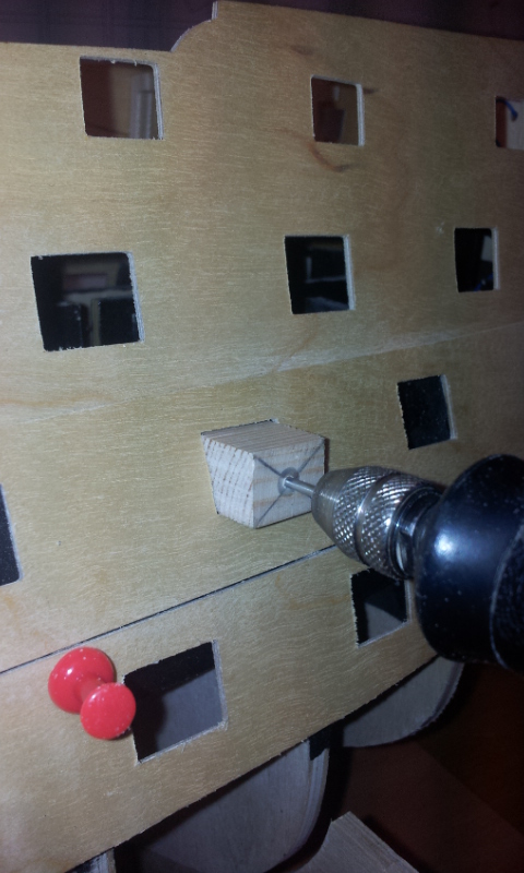
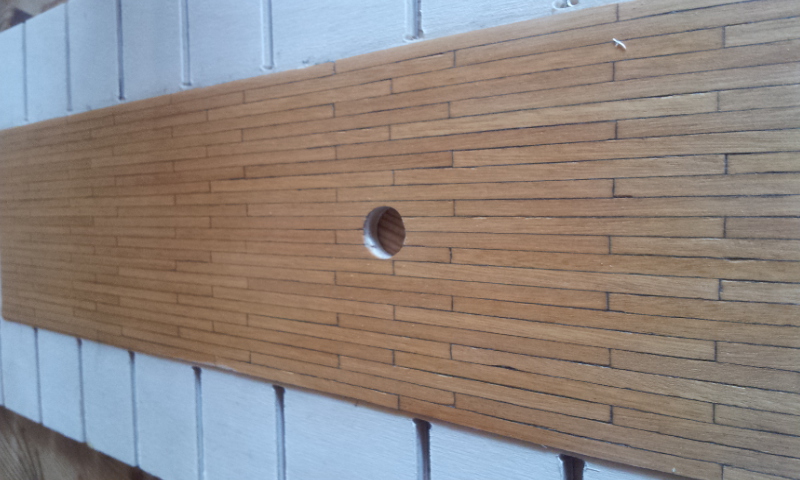
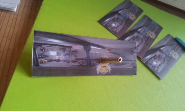
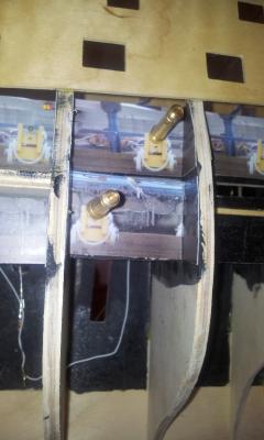
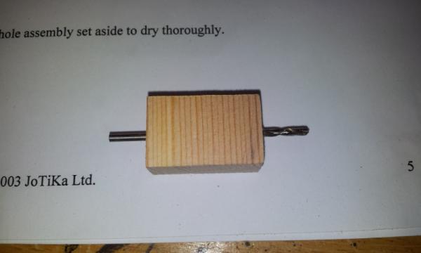
Hello Robipod has kindly provided me with some of his pictures used to make the false guns come alive. I printed theese on photopaper which was stiff enough to be glued in place as is. The challange doing this is to center the pictures to the guns. This is what I did: 1. Dryfitting the gunport patterns 2. Usin a wood jig drilling a centered hole in the false gun support strips (shown earlier in the log 3. Cutting out the picture and centering the guncarriage hole over the drilled hole and folding it to fit btween the bulkheads. 4. Glued the picture in place using one of the false guns as a guide. The last picture shows a dryfit to check the alignment of the false guns. More to come


-
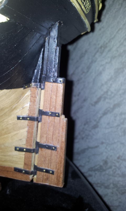
Hello again. Your build is of to a great start When I built this kit (my second build) I did not know what a rabbit was so I did not cut one to the ship. What I did was to plank the exposed plywood with some 0.5mm, or there about walnut colored veneer that I had in my scrapbox from building the Constructo Pandora. This added better coloring to the ply and also kind of enclosed the edges of the planking. A sort of afterconstruction of a rabbit if you will. I also planked the side of the rudder in a similar fashion. Strangly I cant remember any thickness issue. If I remember correctly the rudder was constructed from several pieces (4 or 5) and they pretty much had the same thickness as the false keel. The planking had to be tapered a great deal though. Note that the planking did not run all the way towards the rudder but rather left about 5mm of that hidious ply keel exposed as can be seen in your picture Normally its done like described below: DO READ ALL OF THIS :-) 1. Messure the thickness of the rudder (or sternpost, I cant remember if this kit came with a sternpost or if that was "included" in the false keel.) 2. The thickness of the false keel should be the same? 3. Calculate the thickness of the planking you will add 4. Taper the keel from a imagined rabbit line with the same amount as the thickness of the first planking 5. After the first planking has been done taper this with the same thickness as the second planking 6. After the second planking is done you should have the same thickness as the rudder/sternpost. Example below 1. Thickness of rudder is 5mm 2. Thickness of false keel is 5mm 3. First planking 2mm strips, second planking 1mm strips gives a total of 3mm planking 4. Taper the keel down 2mm to each side from the rabbit to the stern, carfully so that the center of the keel is kept. 5. 2mm first planking to each side plus the 1mm left of the keel and we still have 5mm at the stern 6. Taper down 1mm to each side of the first planking from a redrawn rabbitline and we have 3mm left at the stern 7. 1mm second planking to each sideat the stern plus the 3mm left and hurray we got 5mm left so the rudder will be equally thick. Now for the Corel Victory kit. I would advise against tapering the keel as normally is done as the kit is designed to have the back end of the false keel exposed (hidious I know) but I would imagine that this is suppose to symbolise the sternpost. Doing so will force you to taper the rudder and this can result in problems hard to forsee at this stage. I would suggest that you taper down the first planking to almost nothing at the stern, the smother transition from the first planking to the false keel the better. Also taper the second planking as much as you can without sanding through it. If you by the stern/sternpost have less than 1mm of the second planking visable you can cut a straight line and then plank the exposed ply with some thin veneer to your liking. Small adjustments to the rudder can then be made by sanding down and/or adding the same veneer to achieve the same thickness. Perhaps you can find some veneer that has more the same color as the valnut planking. Mine was not that great. Hope this helps a bit Erik
-
Thats so simple and clever Bob, Why do I never think of theese things. I have the same type of caliper, definitly one of the most used tools in the shop. I have found that measuring something and then press the inch/mm button does just that, and transfers the measurement between inch and mm which comes i handy for us metric folks using US plans and instructions Erik
-
Hello This is what I have learned from working on the LSS Kingfisher kit mentioned above. (Expencive OH YES but the learning curve while building this kit is the best modeling school I could have asked for) I would say that the bottom part of the frame is called "floor timbers" Theese sits on the actual keel. I would imagine that those would have been made from a single piece of timber on a original ship. On top of the floor timbers comes the futtock timbers on each side, and ontop of theese the top timbers. Basicly your basic frame has five pieces to them. Cant frames at the bow and stern of a ship would have been made from fewer timbers, basicly omitting the futtoc timbers. Theese front and back frames would have been constructed in two parts fastened to each side of the keel, or rather the apron at the bow of the ship and the deadwood at the tail. Basicly as Chuck states above the construction of a frame is to complicated for a mainstreem kit and would be far to expencive to mass produce for a small part of the market. Then to continue with the amount of generic parts, out of scale and historicly incorrect details that often comes with your average kit, would be a shame on such intricate frame construction This meens that a manufacturer with any selfesteem would not go with generic parts for such a kit raising the prise even higher. There are very good alternatives out there for instance the Triton online build on MSW. I have not tried this but it seems to be a great concept for the first time out scratch builder, especially the cross section. Erik (seems I like the word basic )
-
Hello Great looking build, I especially admire the clean and smooth look of the paintjob. Are there any secrets to your painting results that you would like to share before I start slabbing at my own Victory :-)) Erik
-
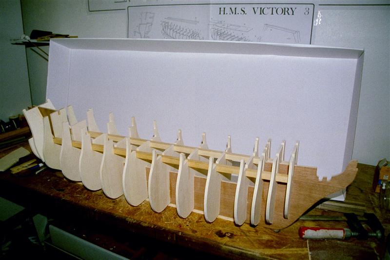
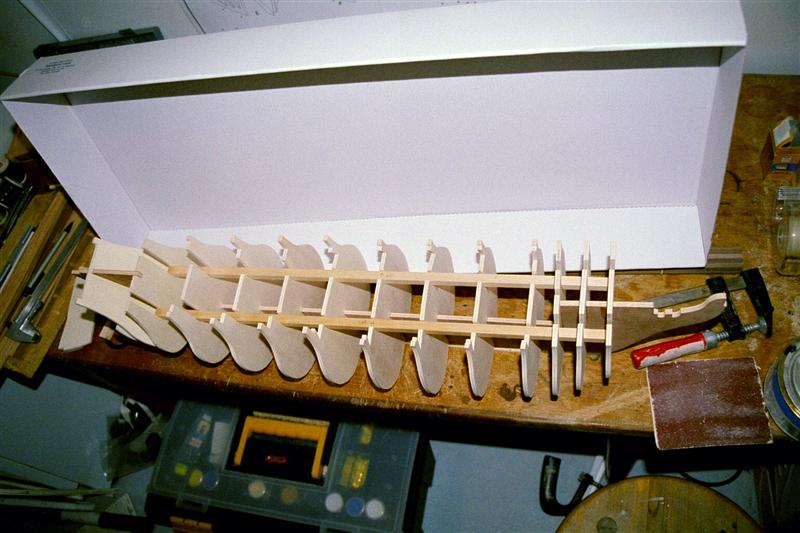
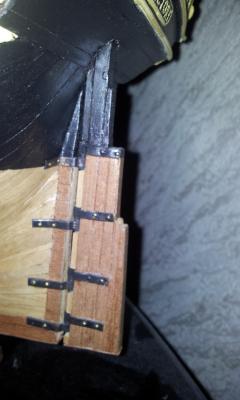
Hello J Pett, great to see you buildlog up. I seem to remember the same problems with part 15-16 on my kit although it was a long time ago. I had a look at the ship and theres no false keel. I simply glued the pieces together and then sanded down the excess of part 16 to achieve a straight keel. I have attached a few pics of how this stage looked on my kit. Regards Erik

-
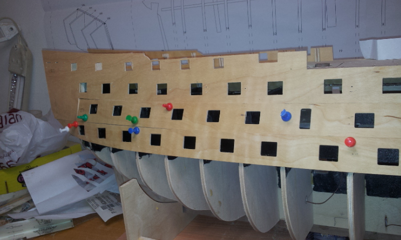
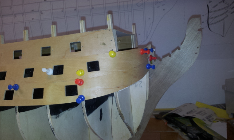
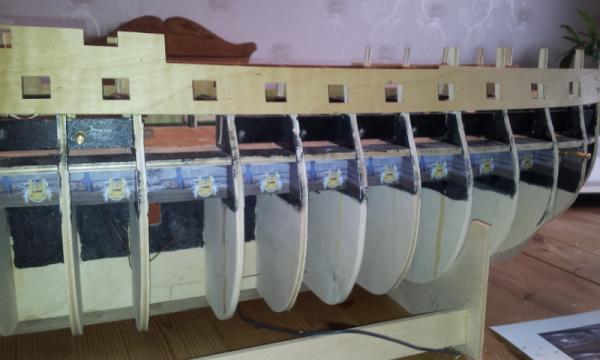
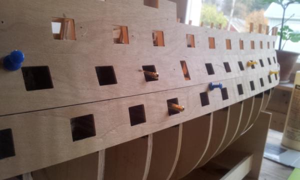
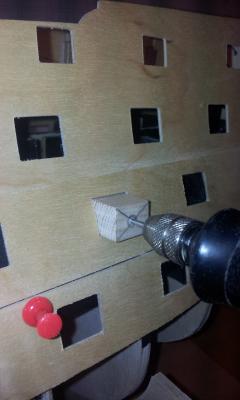
Yes, The wiring goes out through the keel, I have yet to come up with an idea of how to conseal the wiring on dispaly but I probably have a few years to come up with something. I have had a lot of other projects during the summer but Victory has not been idle. A rather serious computor meltdown has resulted in a lot of pictures and materials beeing lost. I really need to learn to make backups more frequently. I rather liked the pictures that Rob has put into the gunports to give them some life. Rob has been kind enough to give me some of his pictures so I can make a similar arrangement. The upper gunportpatterns are now fitted to the ship although the two lower patterns are only dry fitted in order to drill the holes for the false guns. My plan is to drill theese holes centered using a simple little jig that guides the drill. The pictures will then be fitted centering the guncarriges to the holes......Well I´ll post more pictures as I go along. A small problem arose when dryfitting the patterns the middle one portrudes above the bow about 3-4 mm Im not sure if thats correct. The lower one did not fit perfectly at the stern as I had to move it slightly forward in order not to have a bulkhead blocking one of the gunports. I dont think this will be to much of a problem though as it will all be planked over and painted. More to come Erik I

-
kit review 1:85 HMS Pandora - Constructo
Erik Nyren replied to Erik Nyren's topic in REVIEWS: Model kits
Hello Sorry for not answering faster, especially to you silver. If it´s not to late I think I would go for the Artesanina latina Bounty kit. I futures an interresting "open hull" construction which gives you the opportunity to display the inside of the ship. Constructo offers reasonably prised kits though and as such more forgiving of beginners misstakes, then again a quality that perhaps is a bit challenging. jastrzab: Copparing the hull is most likely historicly correct, the practising of copparing hulls to keep the worms away started around 1750 so its likely that HMS Pandora was had theese plates. I would go for coppar tape to create the effect, I have never used it but lots of builders around here has done so and speak warmly of this material. Erik -
Many thanks for your interrest in the build. The treenails are taking me a LOT of time as I´m working on CC Victory parrallell to the Kingfisher project also I have installed a new floor in my house along with some wallpaper along with other projects. well progress is slow and posting a bunch of pictures of treenails and more treenails and.....makes nos sense thus the next post will be of the nailing finished. Nils; Interesting experiment but dit the needle not leave burnmarks on the wood? I think you would be better of with a pinwise actually. Regards Erik
- 43 replies
-
- 1
-

-
- lauck street shipyard
- kingfisher
- (and 1 more)
-
Jim Byrnes Model Machines
Erik Nyren replied to Mahuna's topic in Modeling tools and Workshop Equipment
Hello A small comment on the versitility of the Byrnes table saw. (warning: hardly ship related however tells a lot about the capacity of this saw) I have just finished installing a new laminate floor in my kitchen and dining area of the house and the Byrnes saw was used to cut some pieces of the floor planks with no problems, but the saw really came to it´s right when cutting the lists along the wall and precise 45 degree angles around the staircase. This is my absolute favorite tool in and outside my shop Cheers Erik -
Hello Mr Hunt´s problems with his forum is a story of it´s own, I got cut of aswell and recieved a rather sharp mail after having made a comment deemed inappropriate. Turned out I used an english expression out of context which he read as an insult. I answered and appologised along with explaining that English is not my native language which sometimes can result in missunderstandings. Appologie was accepted but I was never let back on the forum. Still Mr Hunt made fantastic kits and it´s a shame that he was not able to continue the kit-part of his business regardless of bad customer relations. As I understand it he suffers from PTSD after his Vietnam experiences, no excuse but explains a lot. Now on to the kit in question I guess the point of having the frames made thick is to make sure you have ample wood to create the correct shape of the hull especially in the bow area. It´s easier to remove wood than to add it although it´s an everlasting task to fair the hull. I used the dremel drum sander attachment (not sure what it´s called) for the rough sanding and then finished of with sandpaper by hand, no trick to it really only hard labour one small area at a time and lots of breaks. On my Kingfisher I think there are 88 frames in total, it´s a lot bigger and sanding out the interiour is a pain staking task and utterly booring but it has to be done. A good trick is to mix it up with preparing other parts or working on another model to break the repetitative tasks. I work on treenailing my Kingfisher parrallell to a CC Victory kit in order to have variation to the hobby. Unfortunally my Fair American is no longer with me (I gave it to a friend as it fitted nicely in his home) so I can only look at my pictures for reference. Do you have a build log of your FA, It would be great to see some pictures of your ebony and bloodwood replacements when you get to that point. By all means ebony is a beautiful wood but very hard and thus brittle, you have to cut it very thin in order to bend it, let´s say no thicker than 0.5mm. Theres also a health aspect as the ebony dust from what I´ve read on MSW is toxic so make sure you have ample ventilation. Best of luck on the build Erik
-
Intressting comment. The lights in my build are the once for the lower gun deck. More will be added for the remaining decks and gallery later. Do you mean that I should make a backup system or do you figure that threre are to few LEDs? Regards Erik
-
Oh The Admiral liked the colour of my middle gundeck so much she wanted me to put in a Tanyanika kitchen floor ......... Now thats basicly not going to happen but one wonders what such a floor would cost. I guess if I sold my car and the rest of the house along with the grand piano I could almost afford it Regards Erik
-
Middle gundeck planked and finished of with some chinease tung oil then yet again dryfitted on the ship. Chaulking made simle with a leadpeancil against the sides of the plank. A lot of work for a surface that will barely be viseble but good practice on planking Regards Erik

-
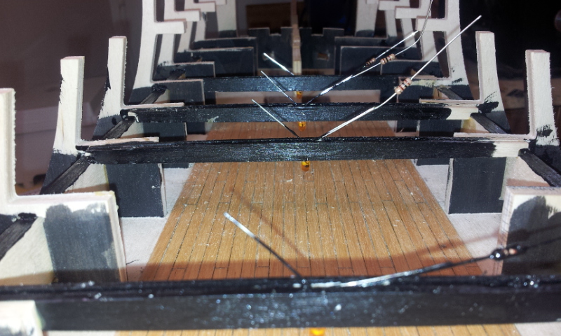
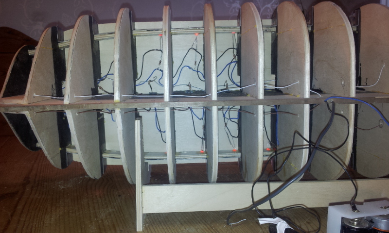
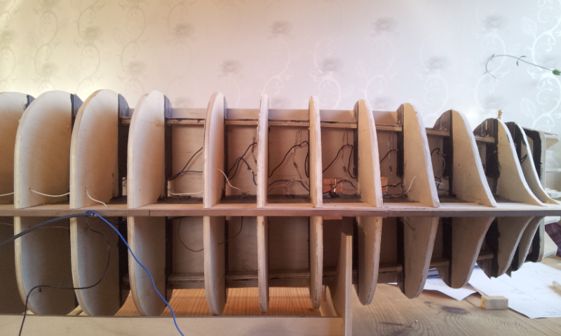
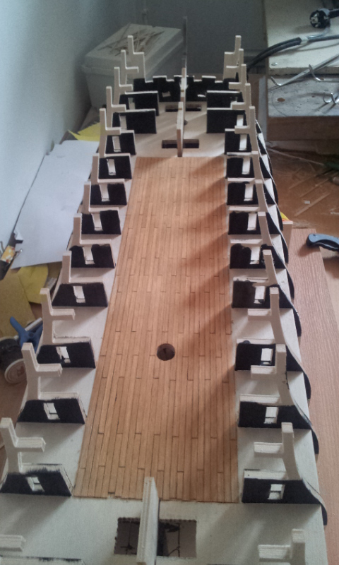
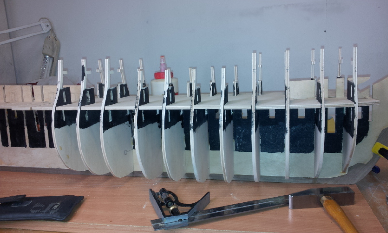
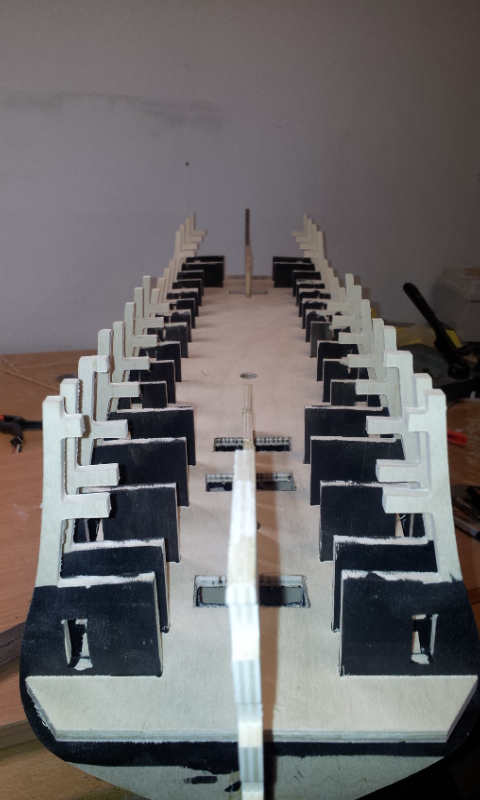
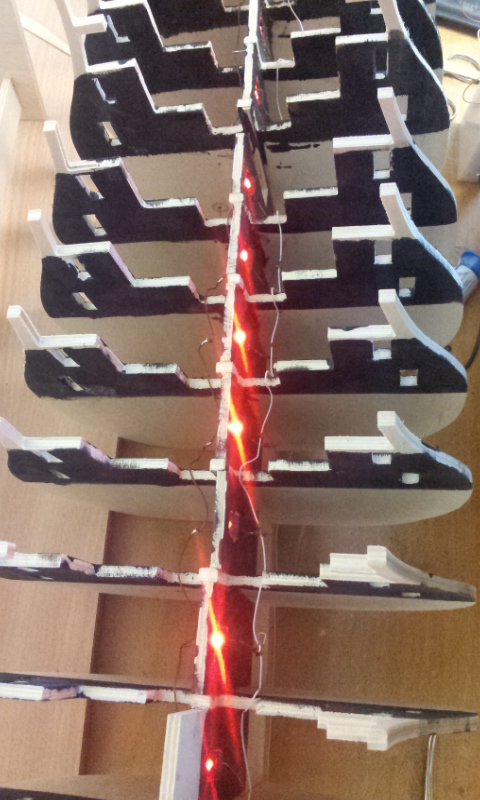
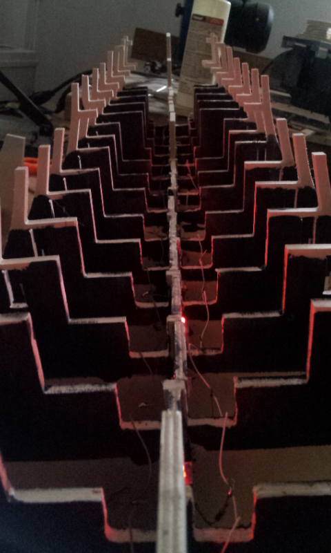
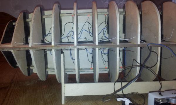
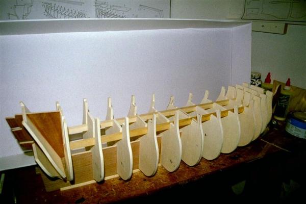
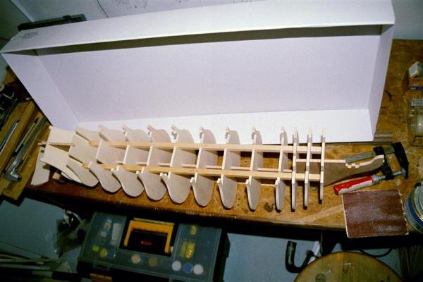
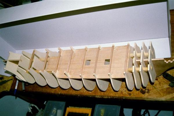
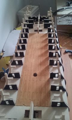
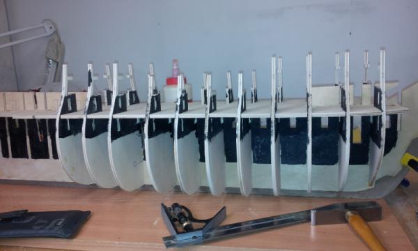
Hello Some progress made today I figured the best way to keep the bulkheads square to the keel would be to use the middle gundeck as a jig. This kit has such excellent precition on the plywood parts that it works well. On the other pictures you can see how I fixed the LEDs into the square holes previosly cut into the keel. Theres one LED to each bulkhead compartment and placing it in the holes lets one LED illuminate both sides of the ship. The wiring is done with one wire to each side a anod and katod side if you will and LEDs with resistors in parralell between the wires. The last picture shows the kind of indirect light that I strive for. The ship will not be strongly lit but rather soft light in the background. The gallery however will be more distinktly lit.


-
Hello Im about to put in my LEDs and have chosen a different approach looking for a more indirect source of illumination. This might cause a shadow effect on the false cannon supports which is hard to forsee. Pics will be added to my log later this week. The deck question is interesting. What occurres to me is that the differense in color can be enhanced by the varying light-conditions and use of camera filters when the pictures are taken. That would mage it hard to tell.Especially if we boil it down to what the decks looked like in 1805. I fear it will come down to personal preferences. I my self will not weather the decks because I want the decks to look as fresh as the paintjob but thats just me. Regards Erik
-
Ok here is my latest thought after loosing some sleep over the issue of the keel not corresponding to the plans. As I have made a dryfit with all bukheads along with the lower and middle deck and everything came together with no adjustments to any of the slots. The problem lies with the plans rather than the keel. What I mean is that if the keel was wrong as much as 8mm there should have been serious problems fitting the decks to the bulkheads. Any comments or similar experiences Erik
-
Thanks all I do the nails in the same manner as you Danny, however I only have a pair of regular wirecutters which unfortunally does not cut that close to the hull. The Makro effect on my cellphone do exaggerate a bit. I tend to use a bit to much glue though, then again I have a few practiceruns to do Regards Erik