
michael101
-
Posts
425 -
Joined
-
Last visited
Content Type
Profiles
Forums
Gallery
Events
Posts posted by michael101
-
-
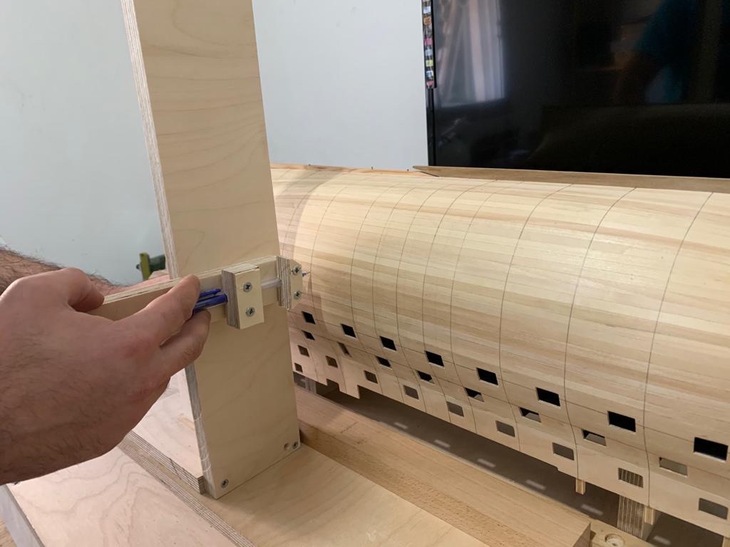
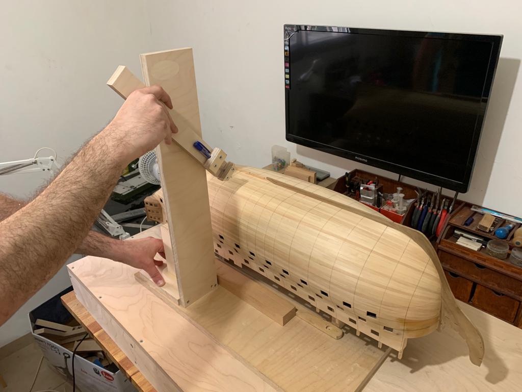
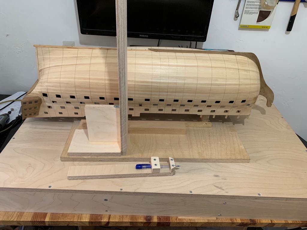
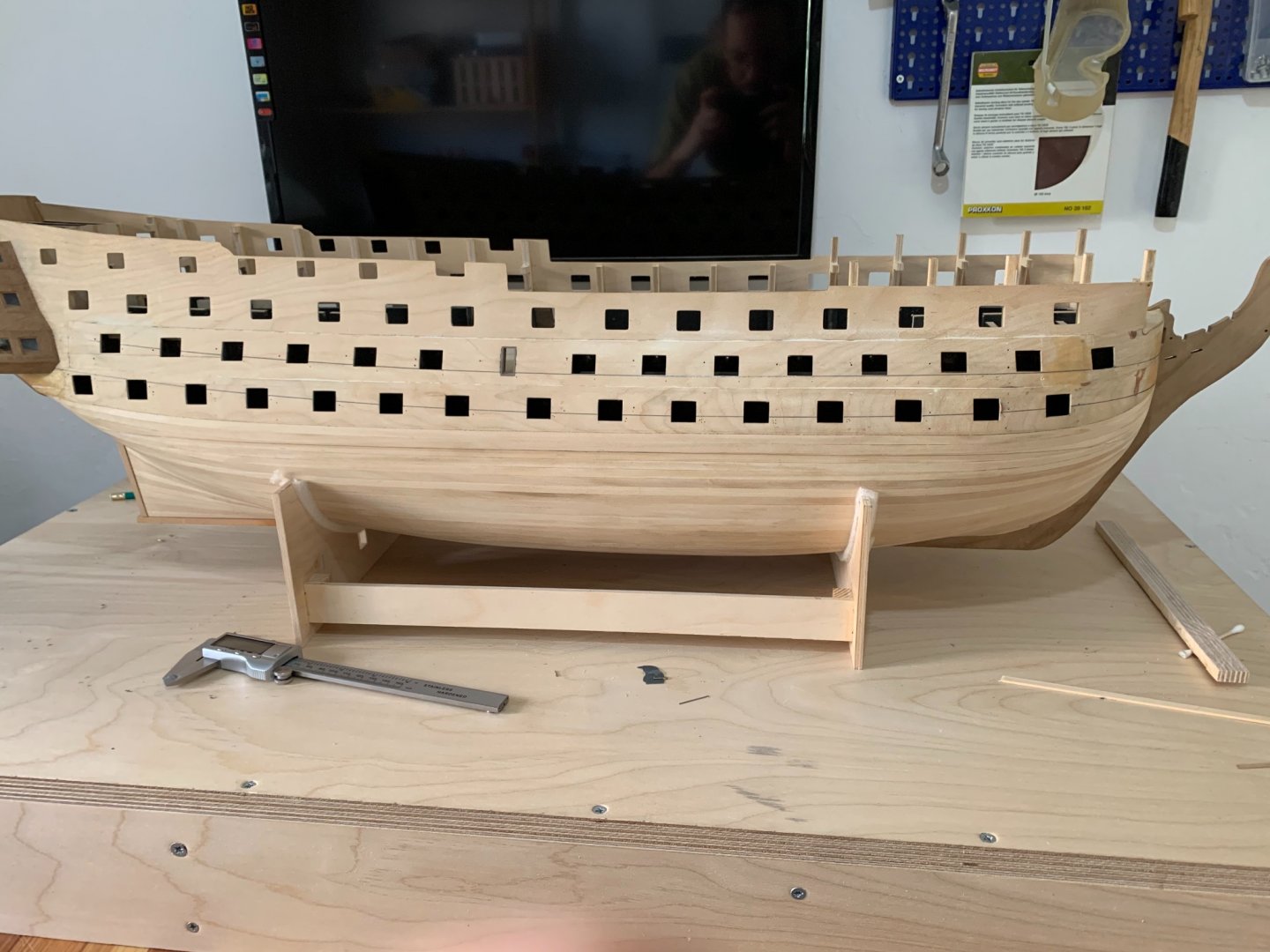
Here is a little update ,
very usefully jig for marking vertical lines on the ship i hope it will help other builders
so, here i have marked the bulkheads lines on the first plank and also the pattern of the butt shift system on the middle of the ship ..
but i will talk about this method later ..
here is some pictures :
Best regards,
Michael.
-
-
What a beautiful process Robert !
you did a perfect job as always !
Best regards,Michael.
-
-
6 hours ago, Robert29 said:
Nice writeup and explanation Michael. Taking your time and planning the best approach to do things always pays off at the end. Keep up your good work Michael.
Robert
Thank you dear friend !
and like you sayid i just taking the time because there is a lot to plan before starting this stage
Best regards
Michael
-
Guid for transferring lines from plans to the model
After a lot of thinking I have found the way to transfer the Wales lines from the plans to the ship you can use the same method for other things you need to copy from the plans in a perfect and exact waySo I’m happy to share my guid with you
")
and hop it will help you !
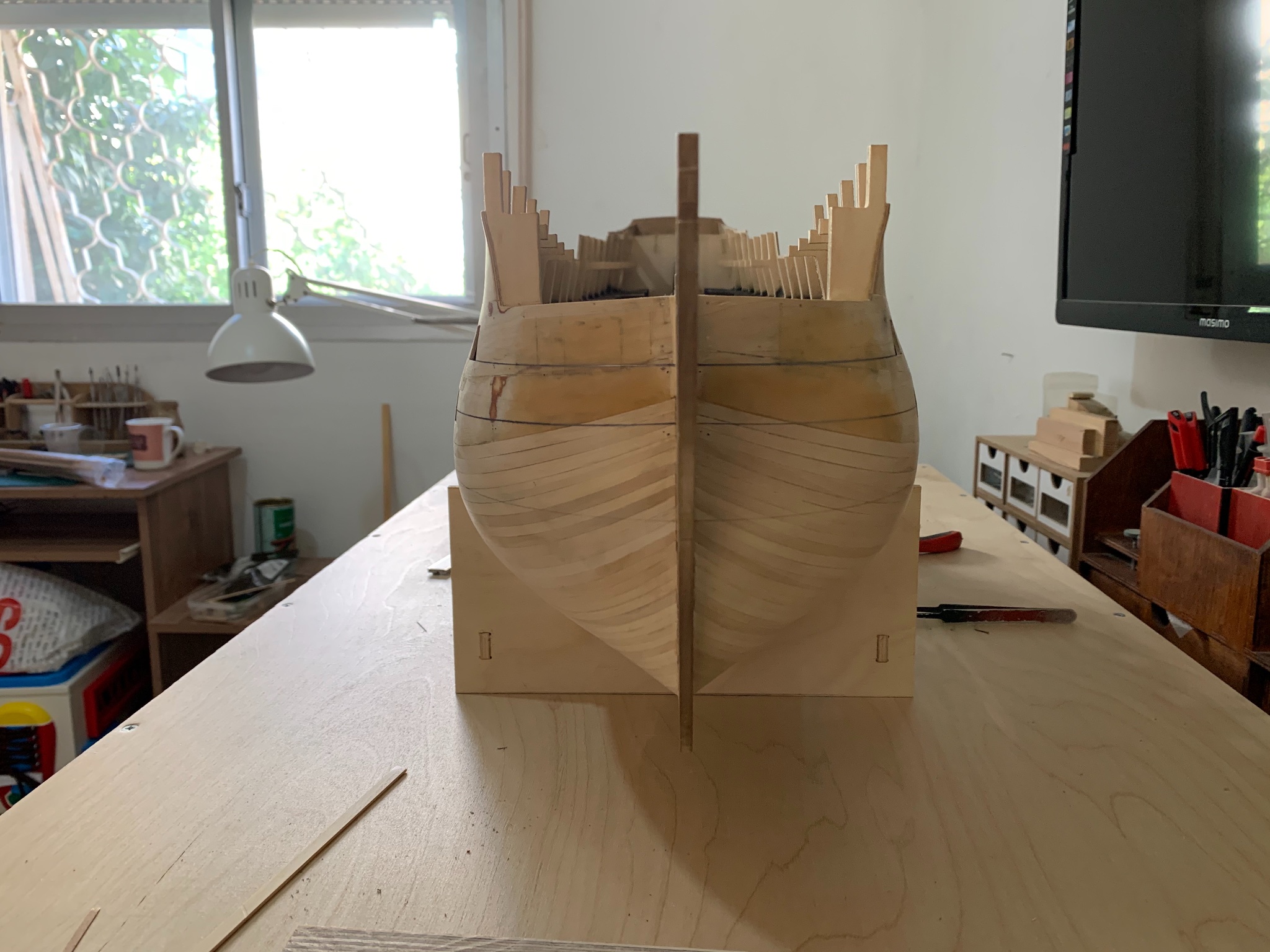
1. First you have to put the ship even on the desk or if it on a stand make sure the ship has the same distance from the table to the keelson at the bow and at the stern !!!!
2. Also make sure the ship is even left and right !
after the ship it’s even left and right also bow and stern are even you can start working (take the tame on this stage it’s very important to have the ship even !)
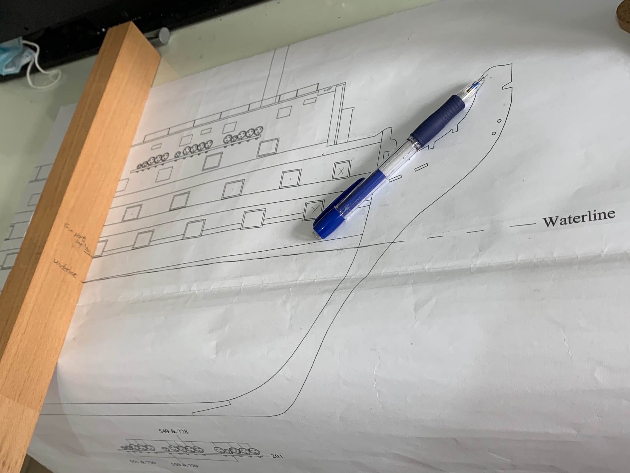
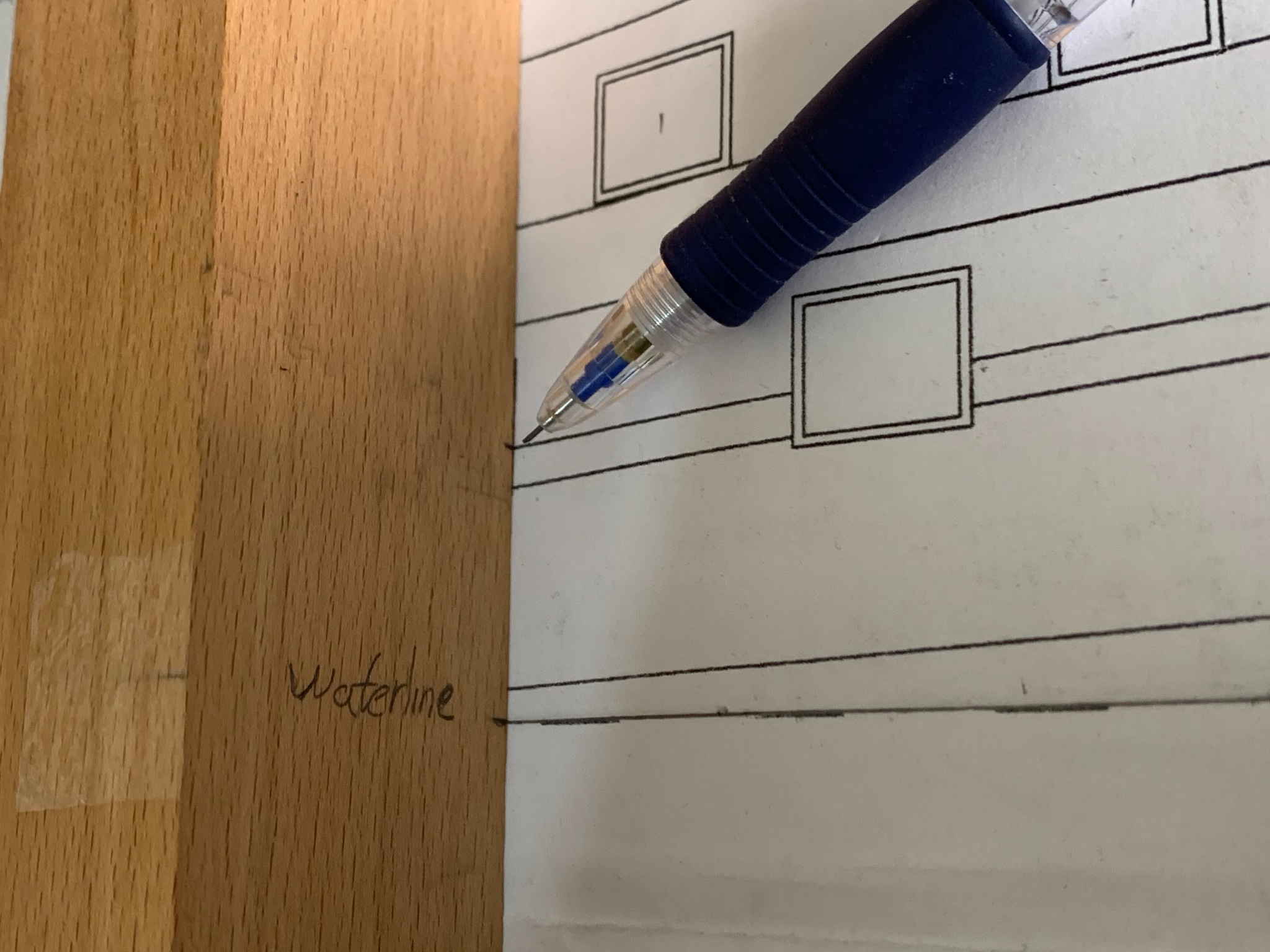
3. now you need to take a reference from the ship to a straight timber (in my case I mark the lower edge of one gunport but you can take reference from other things that you have already on the ship and also on the plan )
4. Now you need to lay down this timber on the plans on the same gunport edge (on the pictures it’s not on the same gunport because I just took pictures to show you the example ... but it must be on the same gunport
when you have it on the exact edge line , mark the water line on the timber :
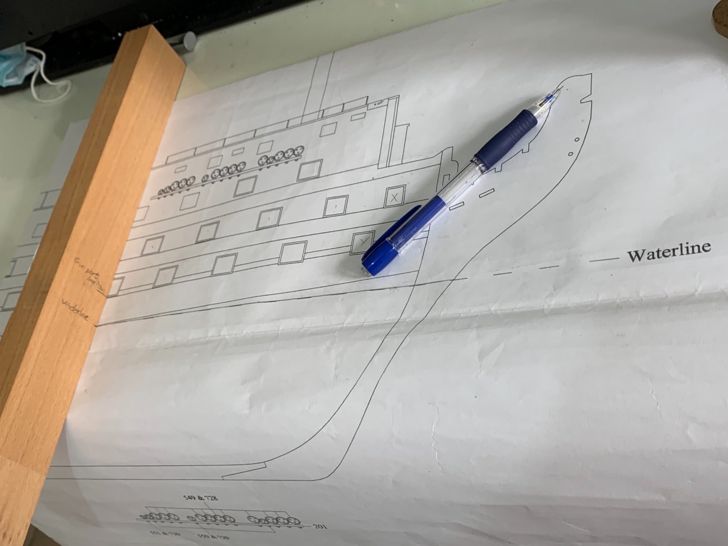
After you have the waterline marked on the timber just erase the gunport edge line from your timbernow when you have the waterline marked on your timber you can start taking a perfect references from the plan!
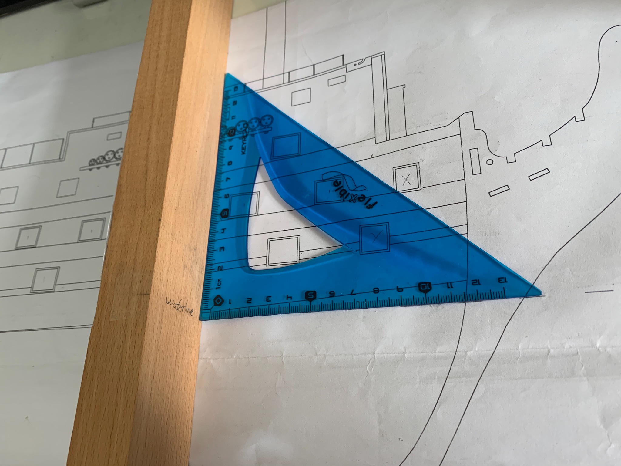
5.now just put the waterline you have marked on your timbre on the waterline of the plan under the mark you want to transfer and use 90 degrees ruler between the timber and the waterline to be sure it’s straight
6. Simply mark the line you want to transfer on the timber in my case it’s the line of the wale:

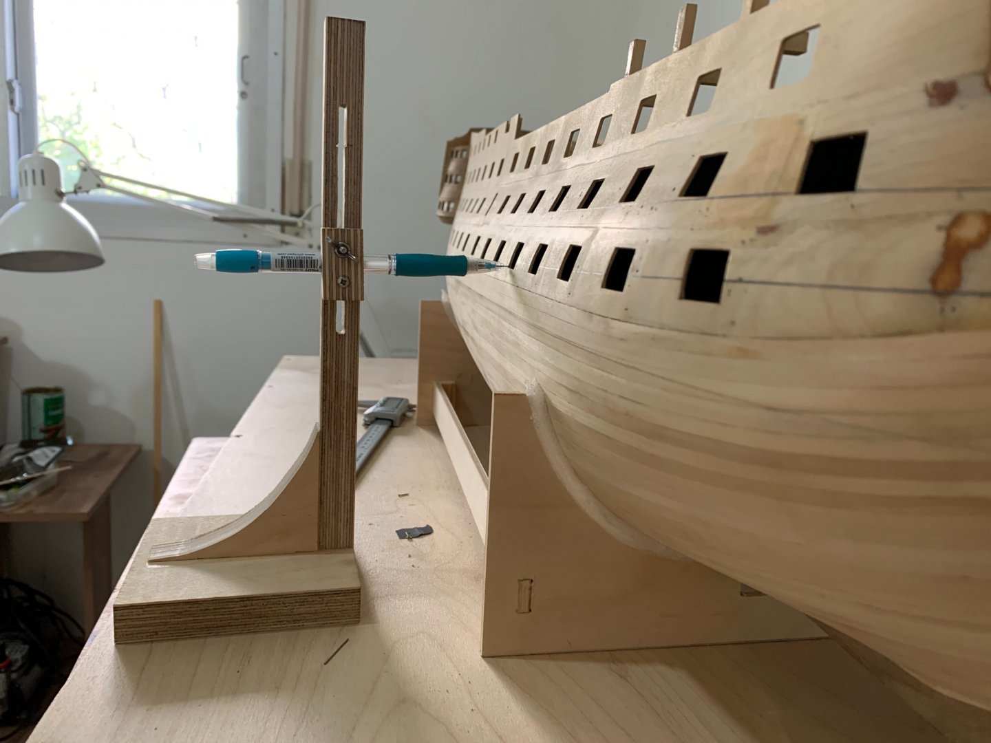
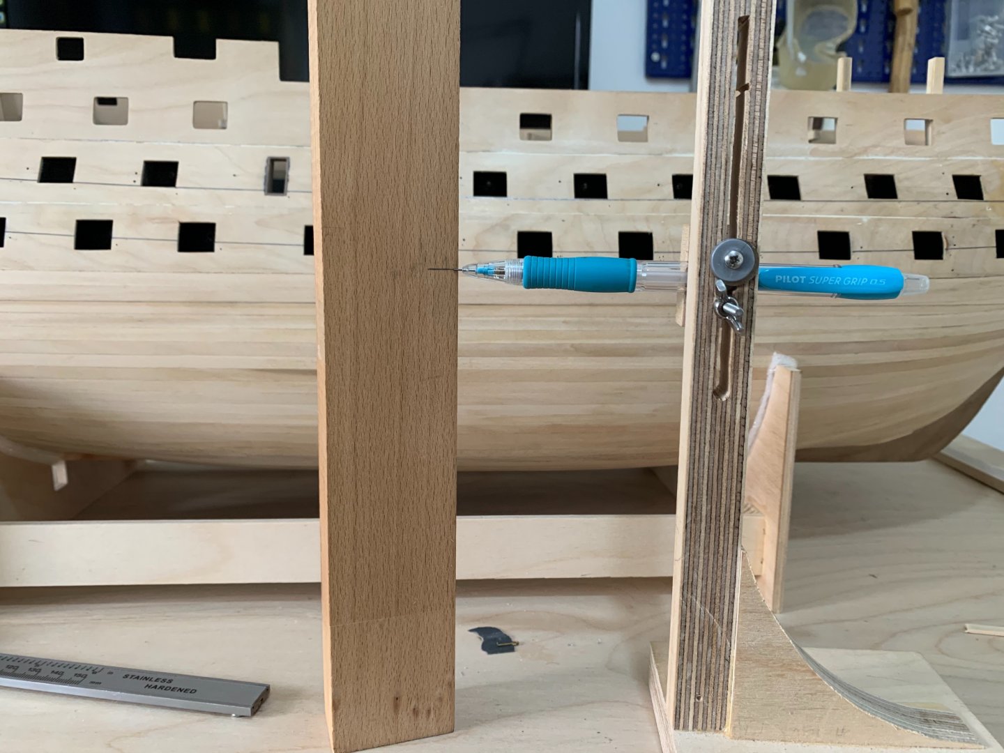
7. When you have it marked on the timber you need to put the timber again on your table and adjust your pencil holder to be exact on the same line
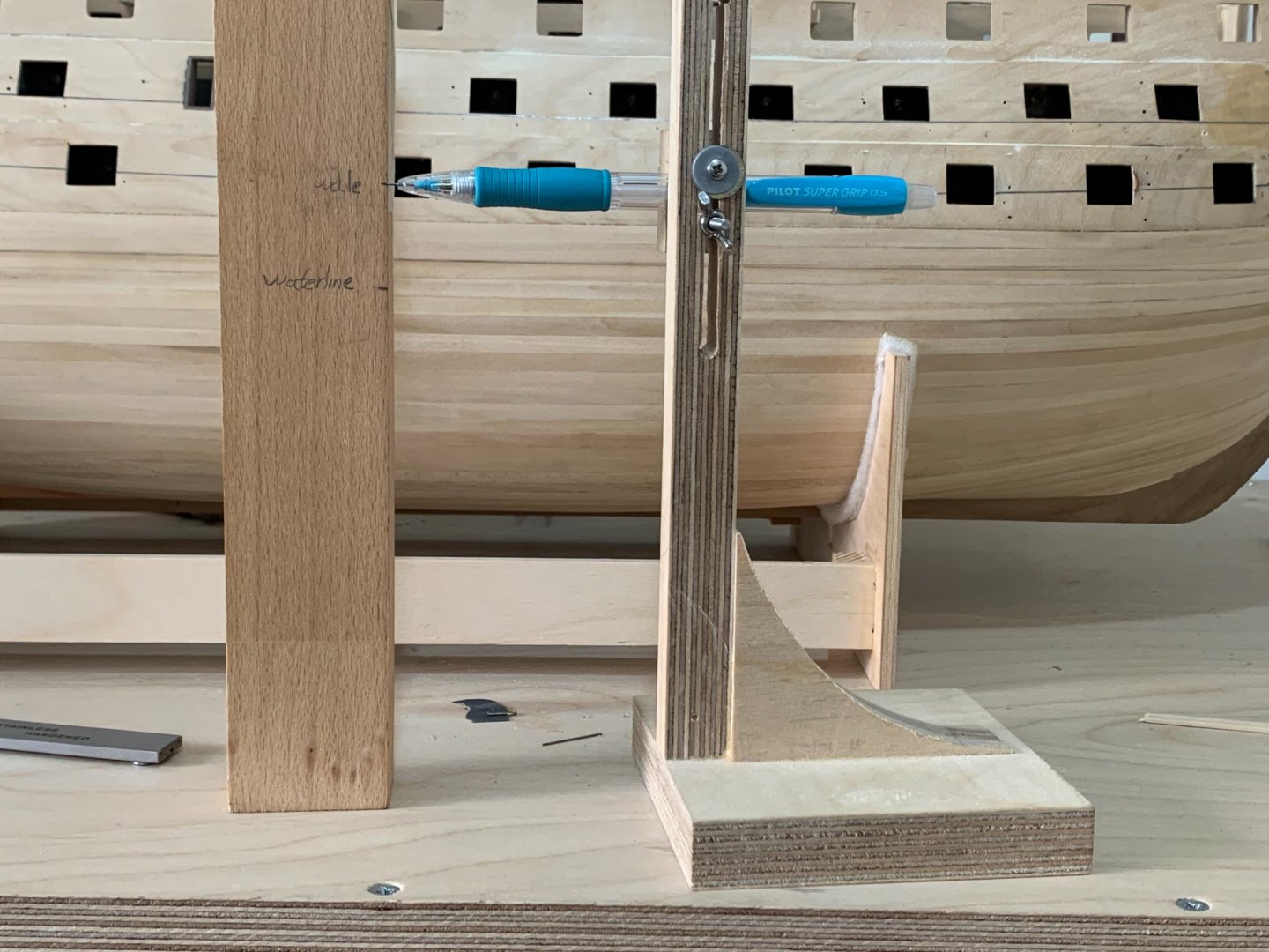
8. Now after adjusting the pencil holder move it and carefully mark the dot on the model
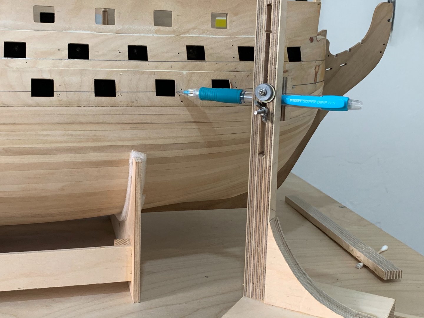
do the same for all the dots you need then put a temporary plank on the ship and connect all the dots by runing a pencil along the plank to get a beautiful line as the plans :
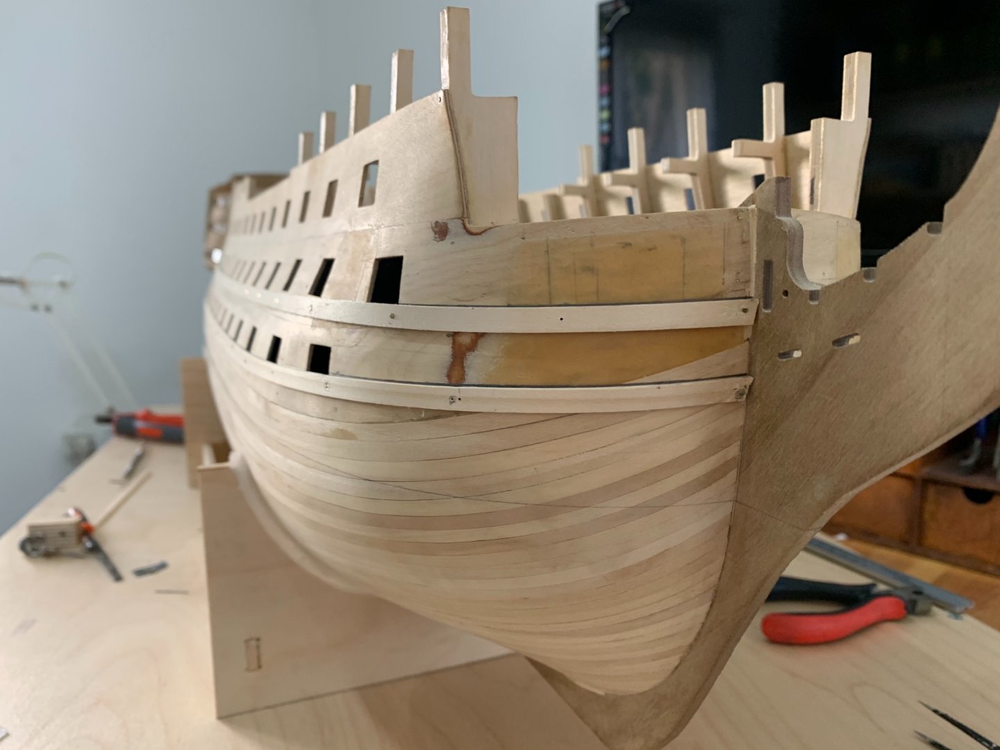
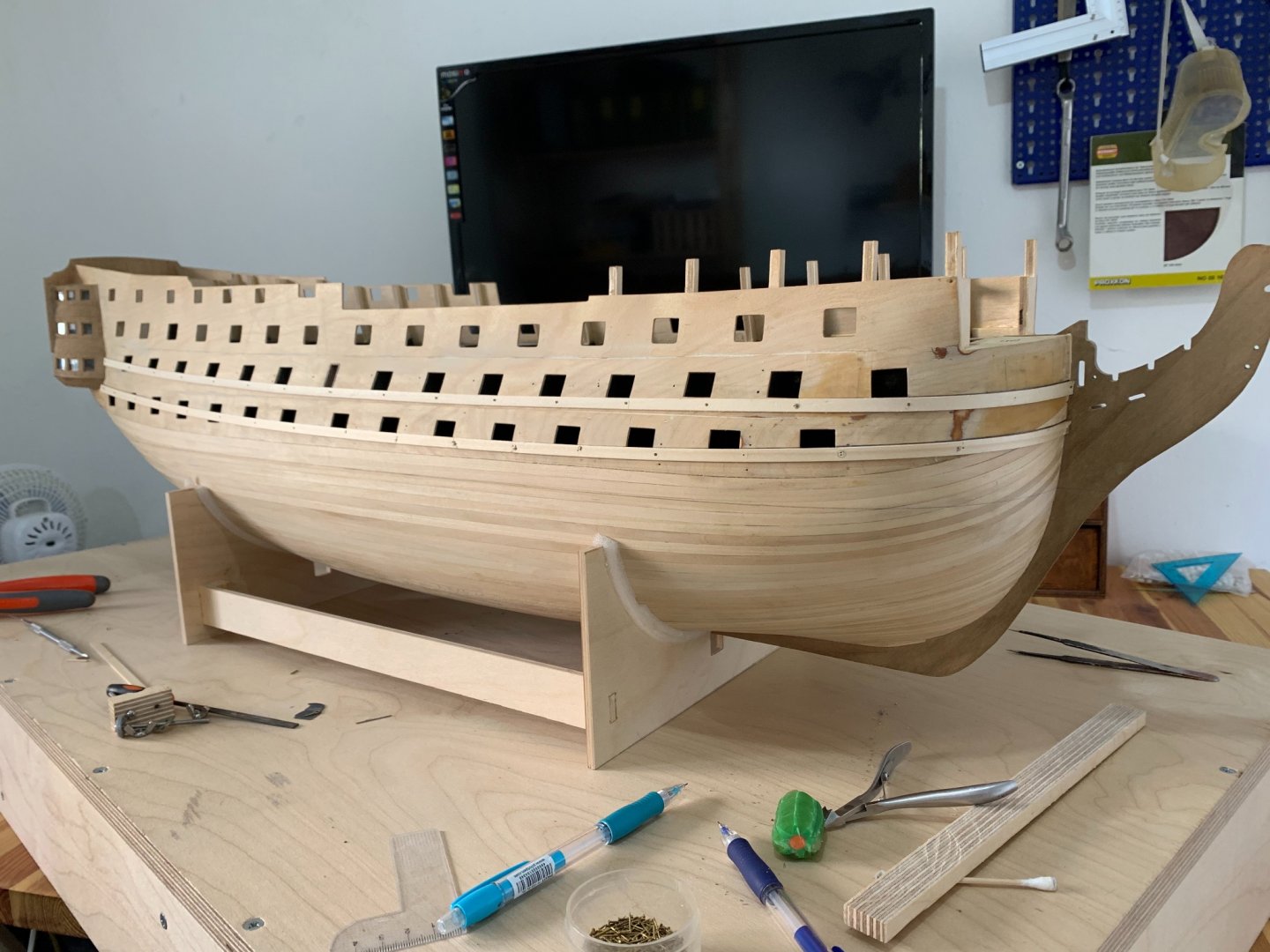
here is pictures after taking the planks out :

-
Hello friends,
here is a new update for my build log ,
at this days I had to mark the Wales on the ship..
the instruction says you need to take reference from each gunport to the wale from the plans and transfer it to the model
by marking a dot then just mark the lines and connect all the dots...
the problem is ; the gun-ports on the model they are far to be exact as the plans (I mean they are not on the same level as the plans but the good thing is they has the same distant between each other !)
and if you taking the reference from each gunport and try to transfer it to the model you getting line with steps and not a nice curve line !
so I decide to take the curve line from the plans and not to do it as a free style and transfer it to the ship ,even it will touch under the gun-ports in a different places and not like the plans
anyway each model plan give a different line even at the book : anatomy of the ship it show the line at different way and not like the caldercraft plan
(no one today can tall where was the line on the real ship because they change it several times when they did renovation to the ship at Portsmouth )
so first I have thinking to mark the waterline on the ship and the to take reference from this line to the wale at the plans then to transfer it to the model
but I wasn’t able to do it because at the model there is a lot of curves an the angel of the caliper wasn’t on the same angel as when you taking the measurement from the plans and it will give you the dot on another place and you will get again line with steps and not a nice curve line !
at the next topic I will show you a nice guide how to transfer lines from the plans to the ship in a perfect manner
-
Thank you friend for all your answers but still im very confuse..
RichardG - even with all the timbers at the front , when you building a big war ship it will be stronger to put long planks a the bow section , if you need to chose what is better 1. To make the 4 butt shift for the beauty of the ship ( and also no one will see that because its under the water aria ...)
2.to make a stronger war ship
im sure the second choice will be better for the risen of the strong war ship ...
————
Allen - I know that no one talk about minimum length of plank , but logical it no make any sense to build a war ship in this manner
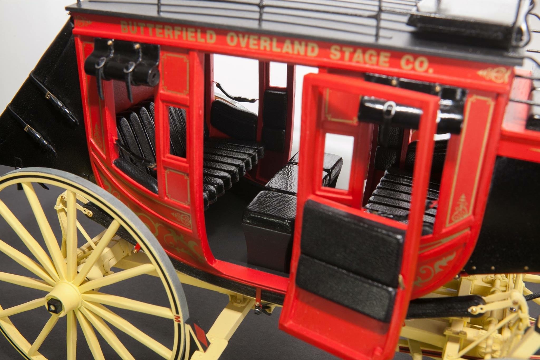
you can see a pictures of the Hms Victory hull, they didnt use the 4 butt shift , and i know that they change all the planks at this days on the victory but believe me .. if the original ship had this shift the museum had to do something similar ..
—————
druxey - im understating your unswear , so you agree with me that at the external planks there is no evidence for the 4 butt shift system
——————
Dziadeczek - it looks nice and i was thinking to do something like that (and avoiding the small planks at the bow aria )but im not sure if its correct because if you avoiding the small planks , it means you will make a big plank and it will be out of scale ..
-
-
51 minutes ago, allanyed said:
Michael,
Look on the RMG Collections site and you will find plank expansion drawings. You will see the butt patterns for both external planking and ceiling/sealing planking on a number of ships. https://collections.rmg.co.uk/collections.html#!csearch;searchTerm=plank_expansion
Allan
Thank you Allan
but you just give me a good example for the issue
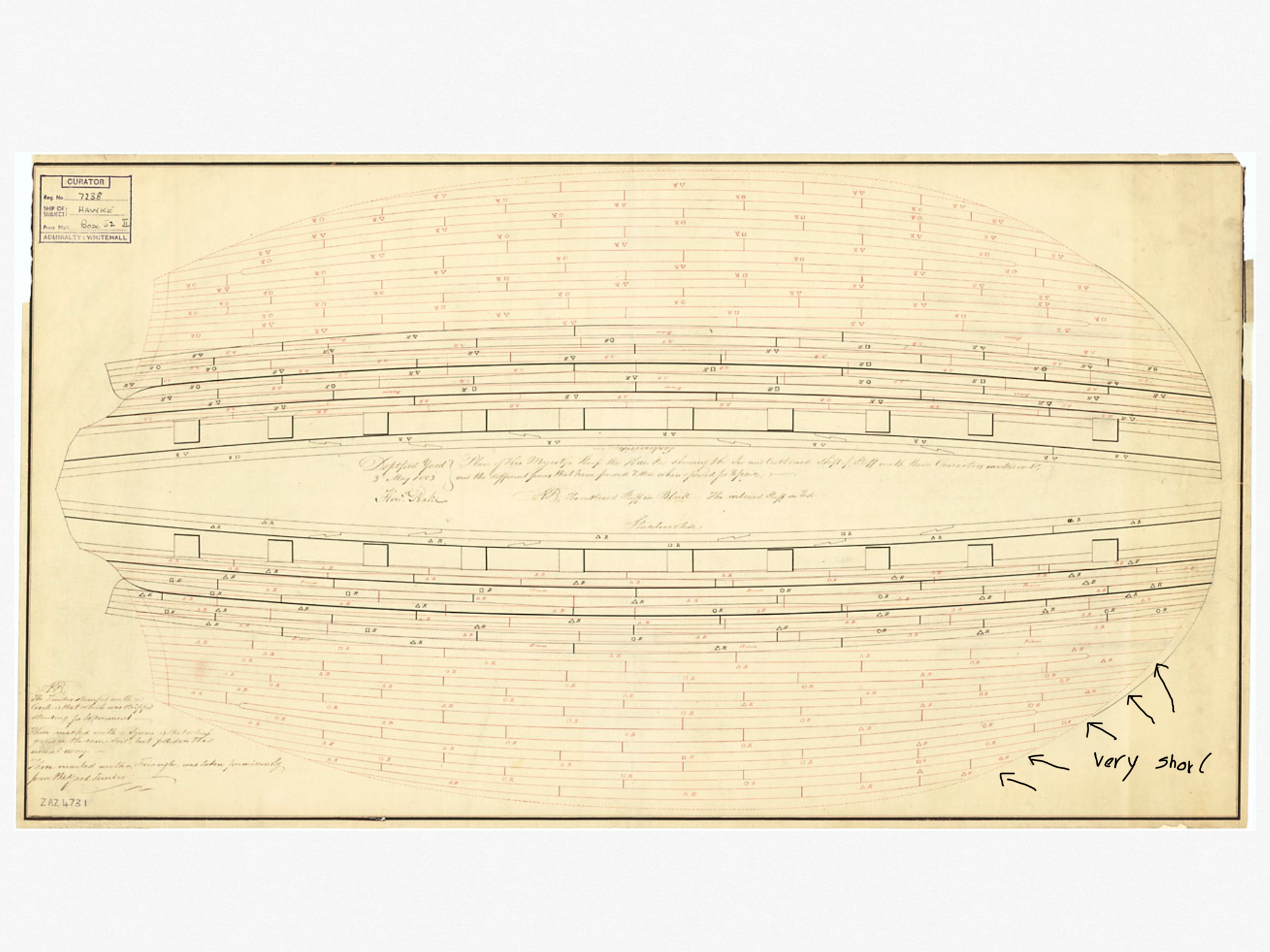
take a look at the first plan of Hawk
look how short they are at the bow section :
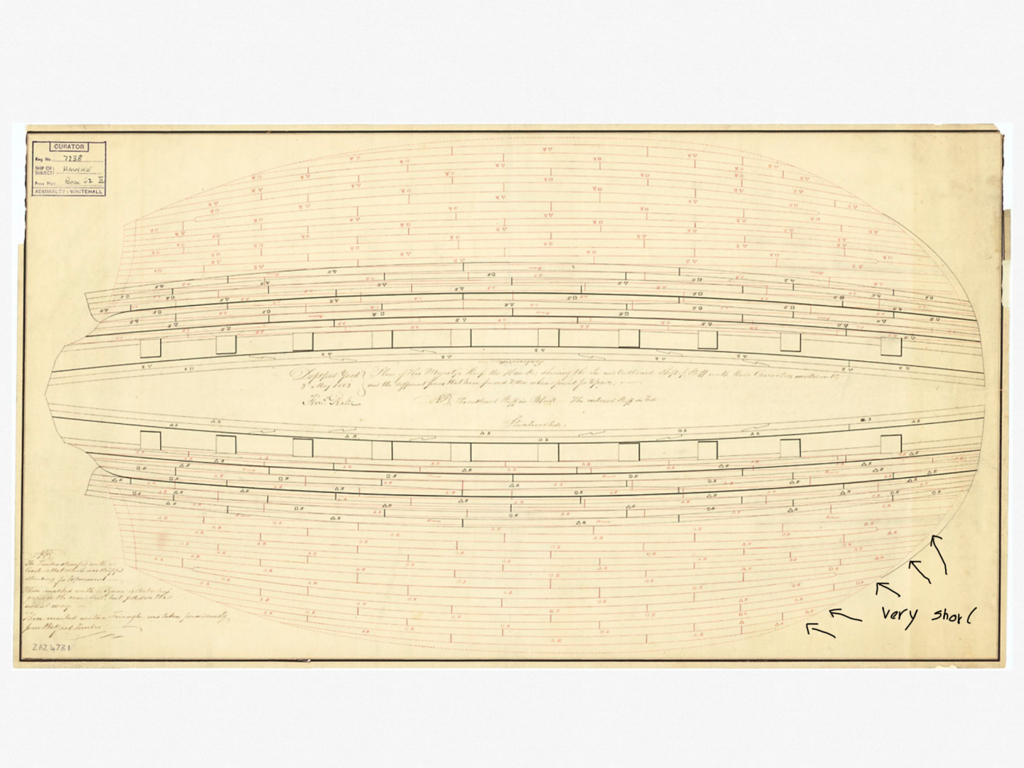
and if you will try to avoid this problem by making the next plank long
it will not have the scale of the real plank ... I mean it will be 1/4 bigger then the plank at the real ship
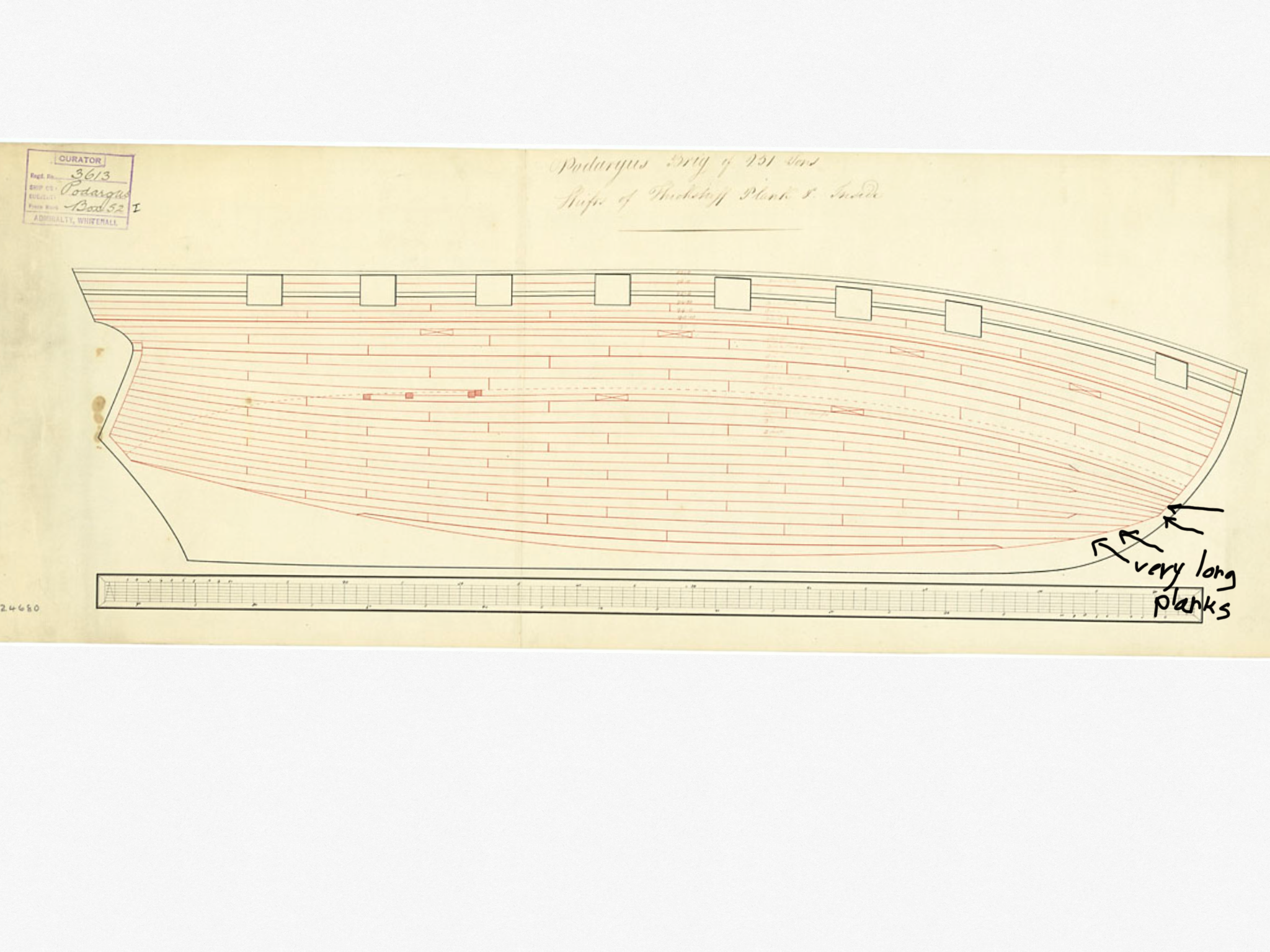
take a look at the Podargus plan:

-
Hello friends ,
Im almost ready to start planking the second planks on my victory project ,
and I saw a lot of build logs (of the victory and other models ) who used the 4 butt shift system...
to be honest it looks beautiful .. but I don’t think they used this method on the real ships
because each plank need to be divided to 4 sections and at each raw the plank will starts his strike from another section
it means every 4 planks we will have1/4 plank how going to touch the keel at the bow aria
and I don’t think it was like this at the real ship
Because most of water pressure it’s on the front of the ship
Is it correct to install 1/4 of plank at the bow section ?!
I will be more than happy to see your comment here
it’s very important for me to discuss this matter with you friends before I will start marking the lines on the model
Best regards
Michael.
- Duanelaker and mtaylor
-
 2
2
-
-
Hello friends ,
is there anyone who has experience with this tool
it looks fantastic for small aria ...
i know proxxon has something similar but the proxxon one it looks like a toy ,
also the vibration of proxxon its horizontal and that one its vertical ! So its much better !
- thibaultron and Moab
-
2
-
-
-
Plywood also getting this problem ..
you can see a lot of build log who had issues with the keel (right from the box !)
and believe me at the factory it was flat ,
dont forget your plywood its about 5-6mm ..(but you can see this problem even at 18mm plywood..)
and about the color black ..
its much better to have shadow inside the gun ports .. mor esthetic and impressive that to see the wood from some angles..
Regards
Michael
-
Hello Roberts,
Great question you asked!
Its nothing to dill with the fairing process
but the reason is :
You can look at wood as a breathable and living material that changes in relation to the climate and humidity of the room in which it is located
In summer it expands and in winter it shrinks
For that, in order not to have any distortion problems in the future
The best way is to seal the wood (keel and bulkheads) with paint!Best regards,
Michael.
-
very clean work !
beautiful
-
Wow EJ !
i didnt know you working on the Royal Louis!
You doing a beautiful work !
Best regardsMichael.
- Old Collingwood and EJ_L
-
2
-
Nice job 👍🏻
just take the time and enjoy the process
Best regards,
Michael.
-
14 minutes ago, GuntherMT said:and your planking looks fantastic, especially for a first planking that will be covered up. I'll follow along for a while but may not have much to say due to my lack of experience with anything with more than 6 guns.
")
Thank you! and welcome to my build log
Best regards
Michael.
-
-
Thank you Roberts
if you need anything feel free to ask
- EJ_L and Roberts Orca
-
1
-
 1
1
-
On 12/22/2020 at 4:21 AM, Diver said:
I am thinking of purchasing the Proxon mini vice with the suction cup base. Do any members have experience with this product, or recommendations for a similar product. Thanks in advance. Bob
Hello Bob,
I have the one with the side holder (for holding the vice to the table)
and very pleased with this precise tool
Best regards,
Michael.


HMS Victory by michael101 - Caldercraft - Scale 1:72
in - Kit build logs for subjects built from 1751 - 1800
Posted
Thank you Kiwiron and Etubino !
now I not have much time to work on my project
but the ship not running anywhere it’s just waiting for me at the workshop")