Louie da fly
-
Posts
7,993 -
Joined
-
Last visited
Content Type
Profiles
Forums
Gallery
Events
Everything posted by Louie da fly
-
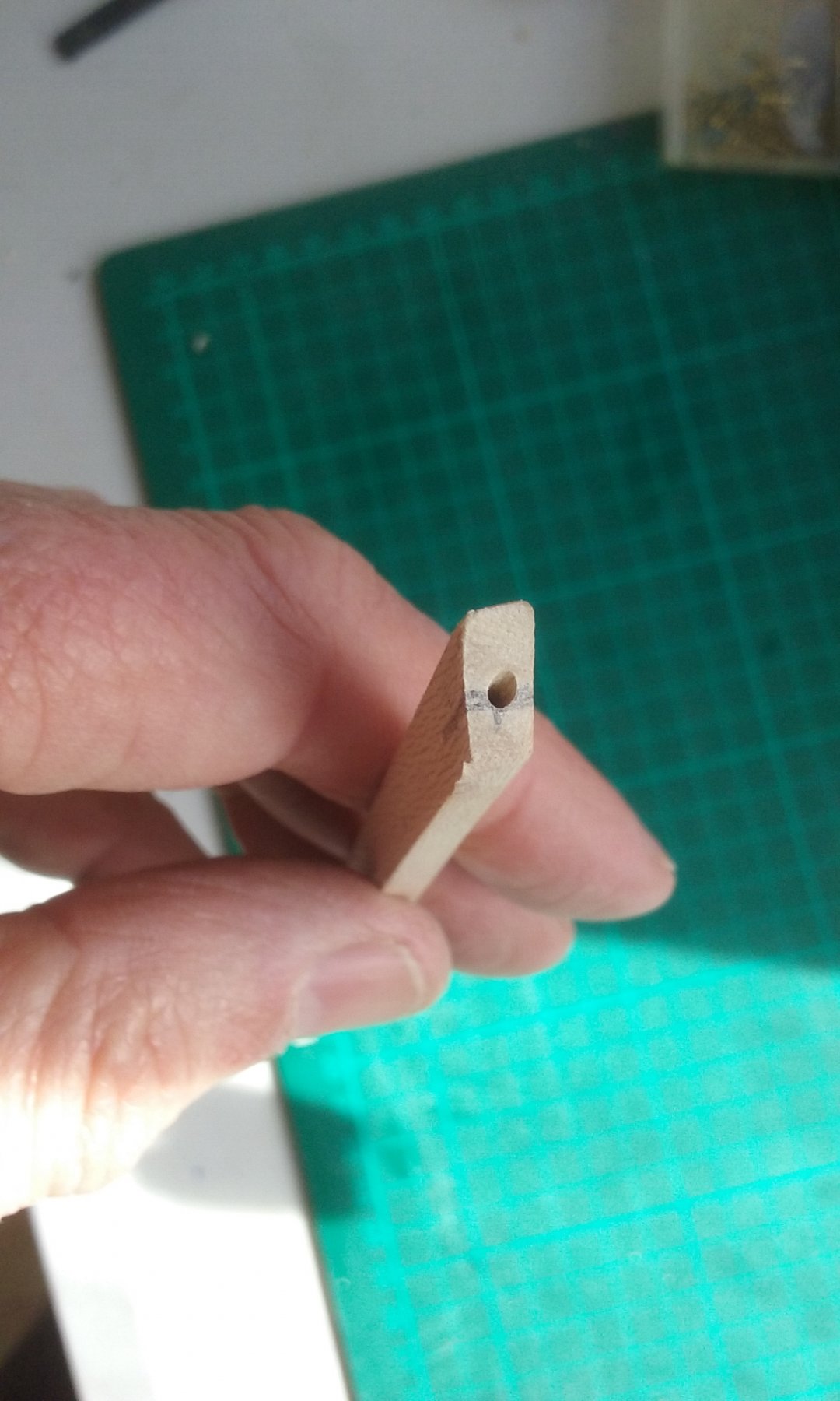
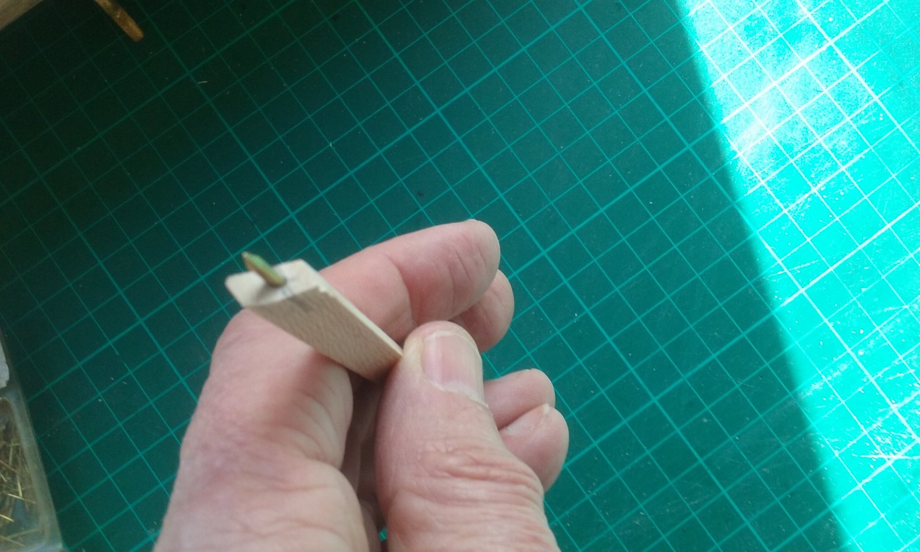
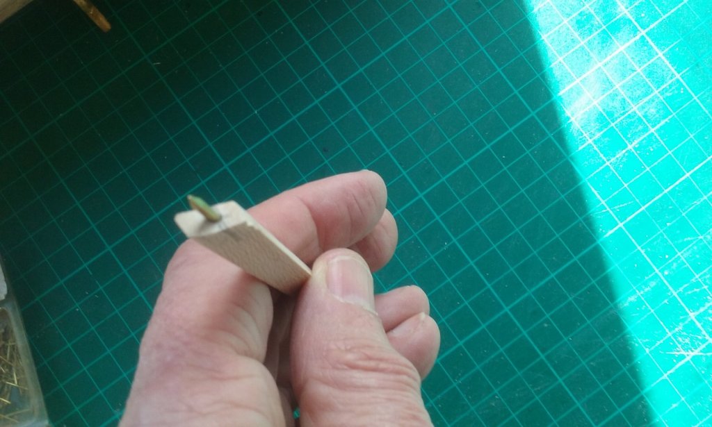
 Spur made and a 'trial' for the katakorax made out of card from a cereal packet. This isn't complete - just one side made, but it could be the way to go so long as I can get it to look like metal. Thanks for the suggestion Carl. A hole drilled in the spur and a corresponding hole in the stempost, to fit a rod (a cut-off escutcheon pin) to enable the two pieces to engage with each other. Having a bit of trouble finding foil of the correct thickness to simulate the metal cladding. My wonderful wife suggested the foil seal you get on the top of a tin of Milo (like Ovaltine, only Australian). Looks like I'll just have to grit my teeth and force myself to drink Milo (it's a rubbish job, but somebody has to do it 😉 ) Steven
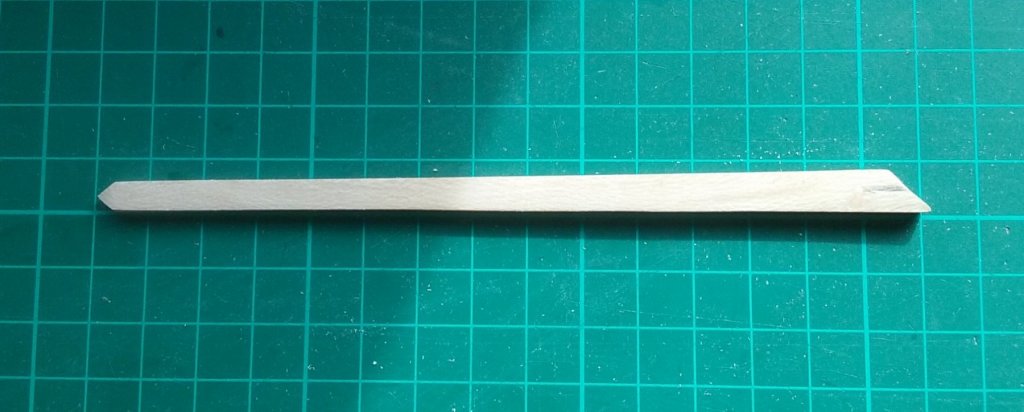


-
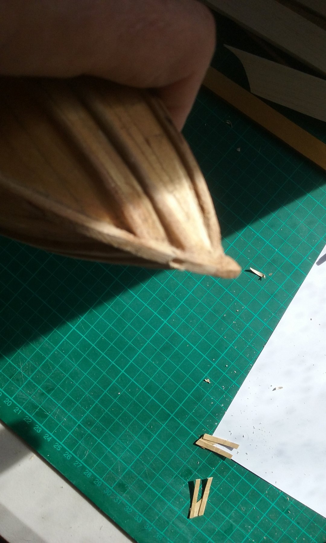
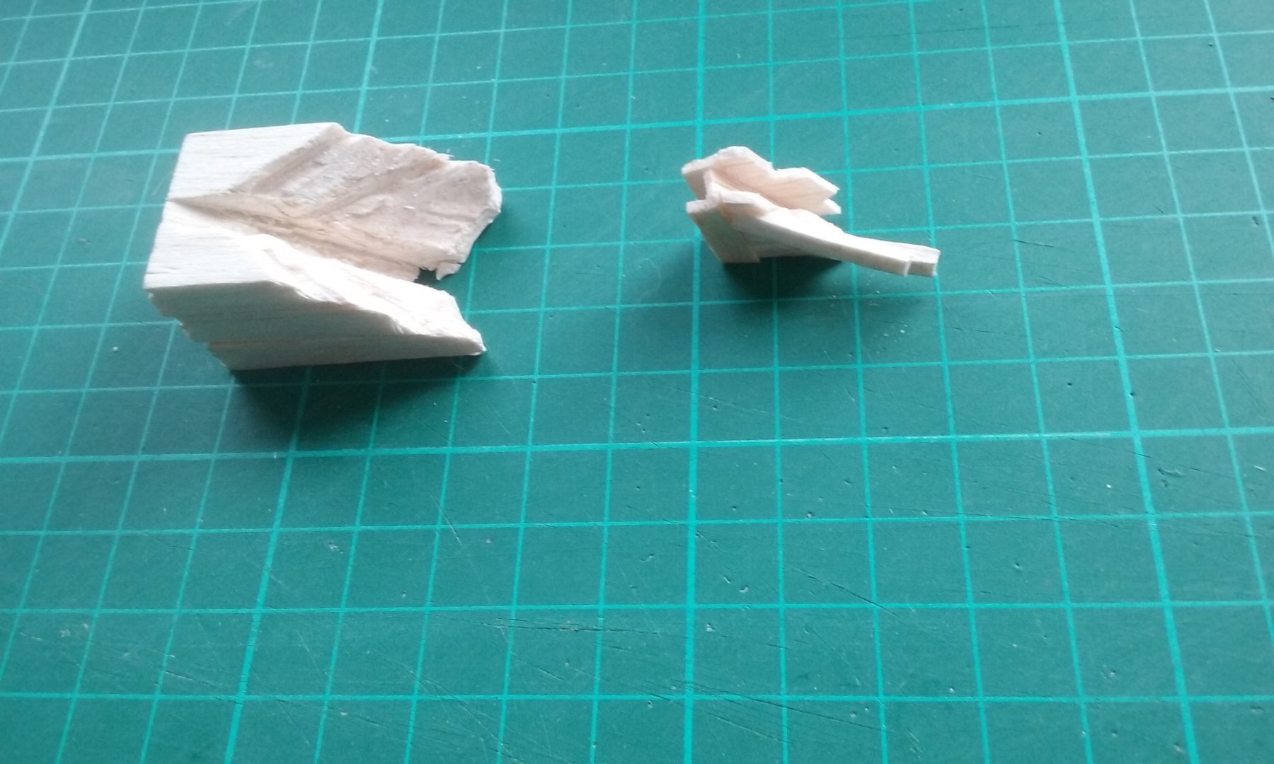
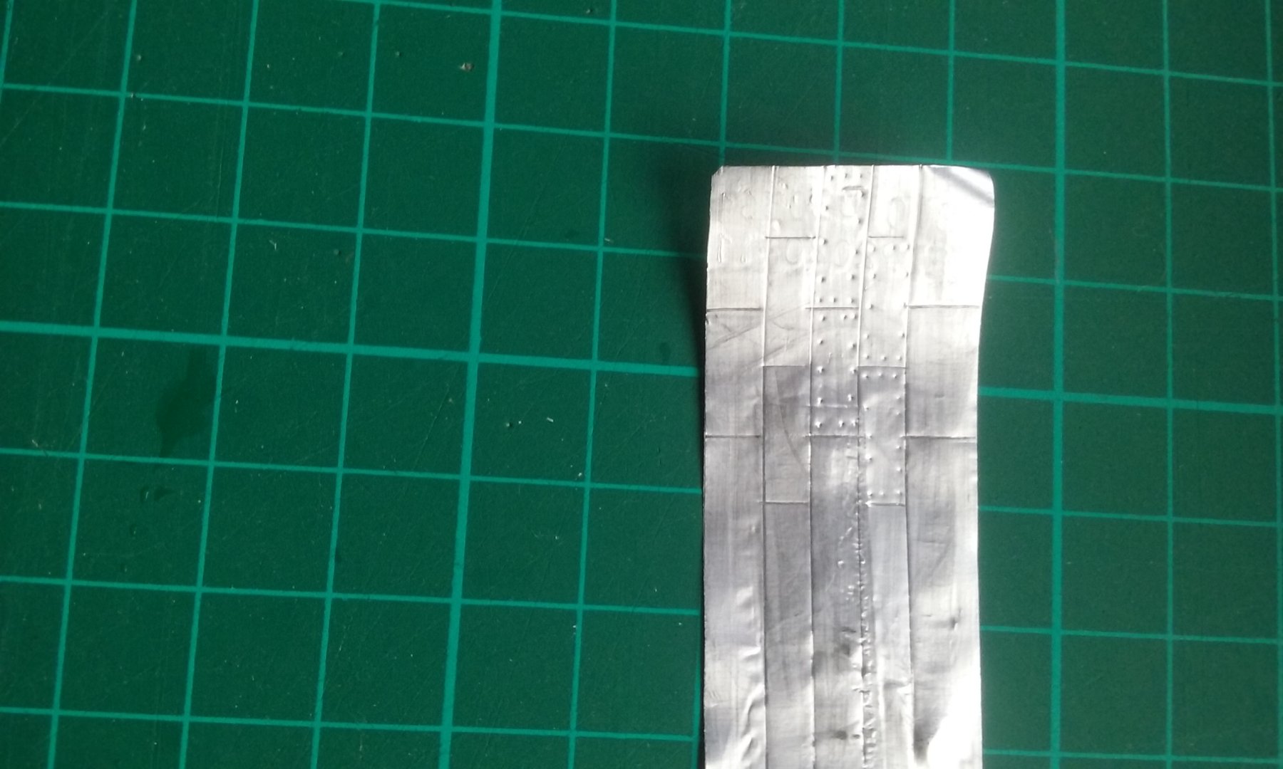
I've been working on the spur, doing test pieces for the katakorax (connector) and the protective metal cladding. Here are a couple of ideas for the katakorax, both made of balsa. The left hand one is carved out of a single block to take the shape of the bow, with the idea of then carving the outside to make the katakorax itself. The right hand one is made of individual pieces glued together. If successful, I'd then use pear wood and I'd probably then have to cast them to make them look like metal. I'm not terribly happy with either one, and I'm thinking of making it out of sculpy instead. Once done it should already look like metal. The reason I haven't tried it in brass is that I'm no good at soldering. And here's my test piece for the metal cladding. A bit rough and ready, but it was just to see if it could be done. I've used the foil packaging the No. 11 scalpel blade comes in. It's thicker than kitchen foil, but does have the disadvantage of having to smooth out embossed lettering and the outline of the paper behind the scalpel blade. If I can get "virgin" foil to this thickness I'll be a lot happier. Steven


-
Thanks for all the likes. Druxey, yes, having the ram holding the ships together would certainly facilitate boarding. Cog, as the spur isn't on the waterline it's not likely to sink the enemy ship. The only circumstance I can think of where the enemy ship would sink is where the spur rides up and over it to capsize it. And unless it goes through the upper works rather than over them, that shouldn't be a problem. However, if it did get caught in the upper works as the enemy ship rolled . . . Roger, I'd heard the term "breast hook" but never bothered to find out what they were. I think they must certainly have been used in a design like this. Thanks for the tip. And yes I agree a spur would have been rather unwieldy, just in normal sailing. In fact one of the reasons I'm in favour of the higher spur rather than waterline is the idea of what a 10 metre spur (or even 7 metres) sticking out at water level would do to the handling of the ship. Thanks also for the quotes. Whether the spur was used as a boarding bridge, if it was resting on (or protruding through) the enemy's upper works after ramming, it would make boarding much more advantageous. It's been determined pretty much for certain that a galley of the 10th to 12th centuries didn't have an apostis, but the principle is the same. Steven
-
Very nice work, Radek. I used to have the book "The Voyage of the Mayflower II". Very enjoyable, but got lost sometime during one of my housemovings. A pity; I used to re-read it every so often. The 1957 reconstruction and voyage are a saga in their own right. You'r doing a very good job of her. Steven
-
Interesting idea, Druxey. This is not specifically mentioned in the sources, though it appears the main tactic was to kill of as many of the enemy as possible with missile weapons and then take the ship by boarding. Whether the spur would be the most effective “bridge” is another question, especially as the forecastle and the side castles were higher than the enemy deck. Messis, this is an interesting interpretation. However, the model was made quite a long time ago and more recent discoveries and developments have modified ideas of how a dromon appeared. Many of the features described in the Byzantine sources appear on this model - the only major thing that I’d disagree with is that this vessel would have been far too heavy for oarsmen to row. There are a huge number of ways to combine the known features of a dromon to make a reconstruction. Age of the Galley alone contains three reconstructions by three different people – all very different from each other - and I know of at least two others apart from the one you’ve posted. In my opinion the reconstruction in Age of the Dromon puts them together in the most believable (and beautiful!) configuration – but even that now has to be modified by the Yenikapi wrecks discovered in the old Harbour of Theodosios in Constantinople/Istanbul. This always the problem with speculative reconstructions. New discoveries can so easily make them out of date. And if a dromon is discovered among the wrecks found in the Black Sea, I expect my own reconstruction will immediately become out of date. Such is life. Steven
-
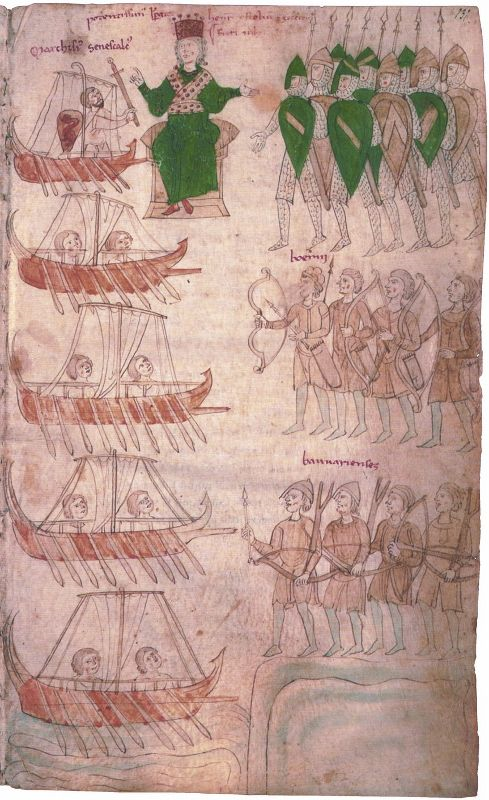
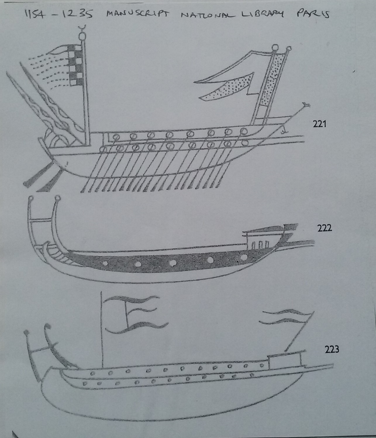
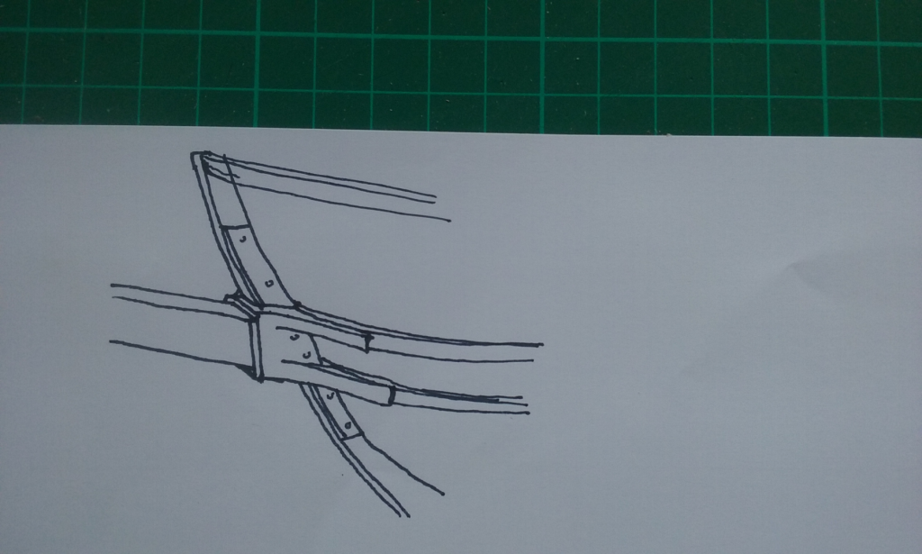
More spurs above water level; all West European, all somewhat later than the period in question, but indicative that spurs above water level were what was used. Unfortunately there are no surviving representations of galleys with their spurs from the 10th or 11th century, neither Byzantine nor any other. However, beginning with the 1993 Maritime Mirror article by Frederick van Doornick Jr and expanded on by Prof Pryor, first in Age of the Galley and later at more length in Age of the Dromon, it has been firmly established that Byzantine dromons had raised spurs, not waterline rams. From the Liber ad Honorem Augusti, late 12th/early 13th century Italian. And here is my first draft of how the katakorax might have fixed the spur to the bow of a dromon. Theoretical only, and I'll have to make it in 3D (probably in plasticiene) to check that it would work. In real life it could have been constructed of wrought iron, but it might have been easier to cast it in bronze. I'd meant to draw nails/rivets through the "knees" into the wales, but forgot. Perhaps it should also have a solid back to it and extend further forward as a socket for the spur rather than have the spur directly against the stempost , but this is after all a first draft. By the way, the pictures above have inspired me to reconsider the height of the forecastle. I realise the proportions on mediaeval pictures can't be totally relied upon, but all of the forecastles shown are lower than the one I've worked up for the dromon. On the other hand, these don't have to allow room below the forecastle for the Greek Fire apparatus. Still thinking about it. Steven


-
That's true, Druxey, but by the time of the dromon shipbuilding had changed. The Ancients built plank first - or perhaps even plank only - with the planks held together edge to edge by "coaks" - small tenons recessed into mortises in the edges of each adjoining plank at close intervals. The waterline ram of the Ancients was able to either break the coaks or rip the mortises out of the planks, resulting in either the planks separating, or split the planks themselves - either way catastrophic failure. Once framed construction came in, ships were too strongly built for this to work any more, and the spur came to replace the waterline ram. GrandpaPhil, the earlier spurs do seem to have been built as an extension of the keel (see the first picture in my post above) but later the fixing point seems to have risen, till by the period I'm dealing with it was about halfway up the stem. By the way, here's another picture of a galley with a spur held from above (Spanish, 13th century - the Cantigas de Santa Maria.) The spur is on the left of the picture. Steven

-
You can always come to sunny Ballarat, Carl. Tonight it will 3 degrees C, 12 degrees tomorrow. Just make sure you come in winter! (It gets up to 35 or even 40 in summer.) Of course, Greg lives in Canberra. Brrrr! Steven
- 292 replies
-
- 4
-

-
- g class destroyer
- trumpeter
- (and 4 more)
-
Roter Löwe 1597 by Ondras71
Louie da fly replied to Ondras71's topic in - Build logs for subjects built 1501 - 1750
Beautiful work, Ondras! -
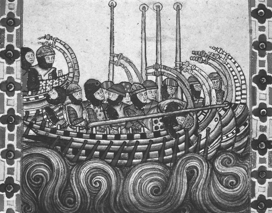
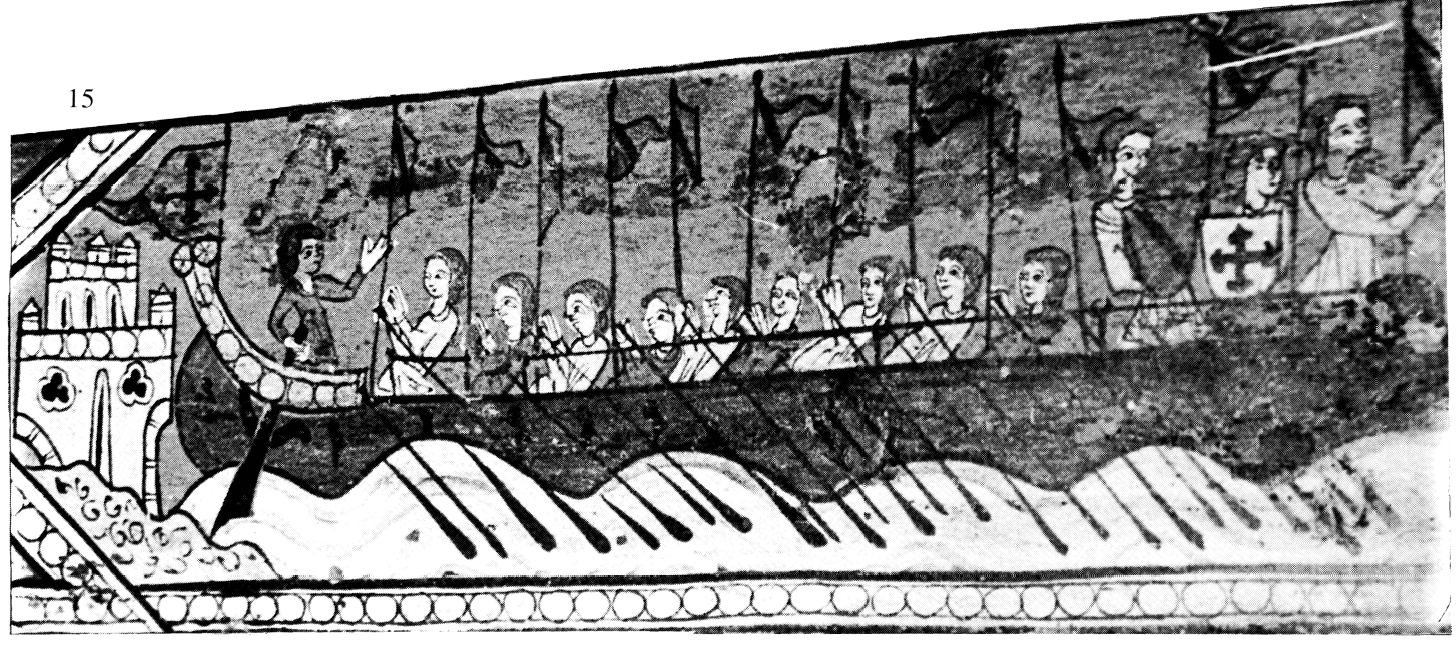
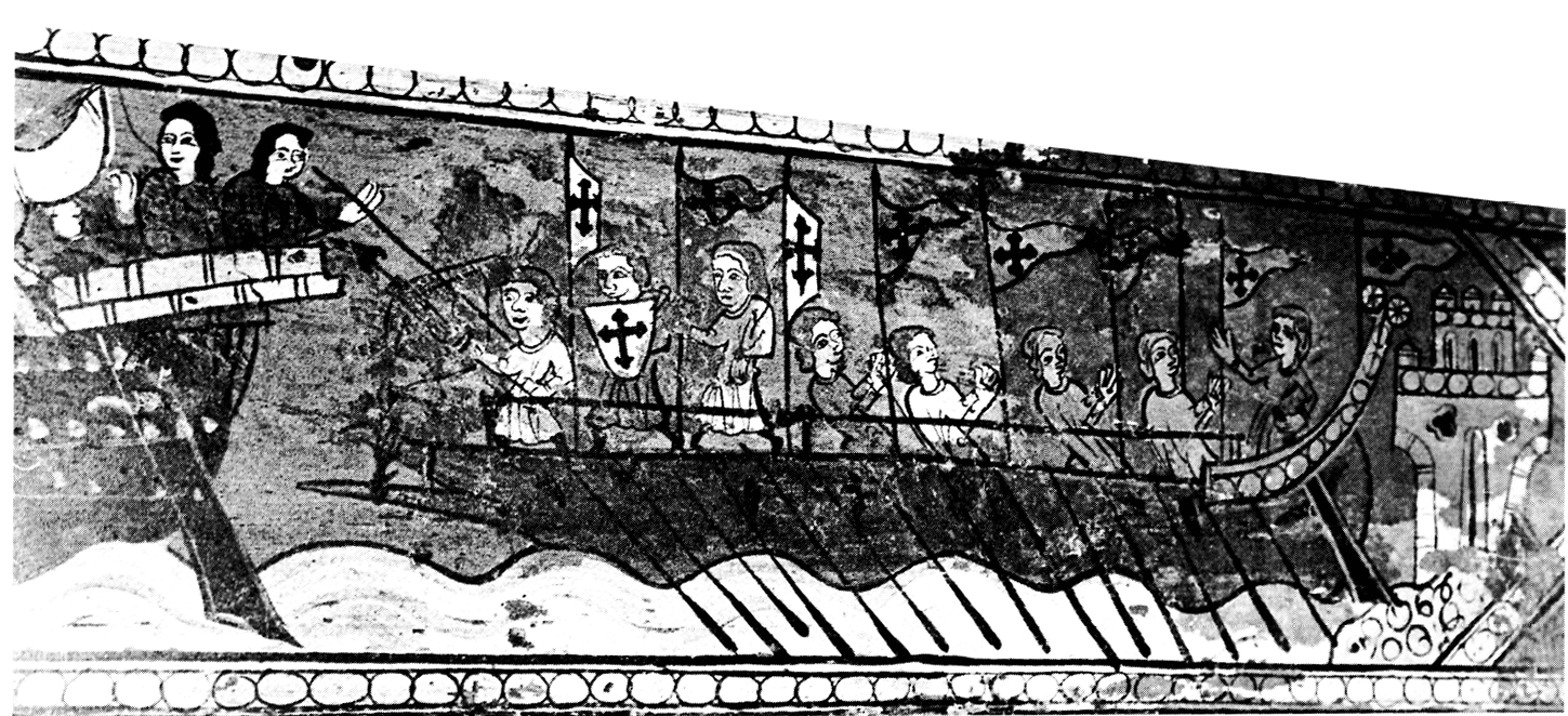
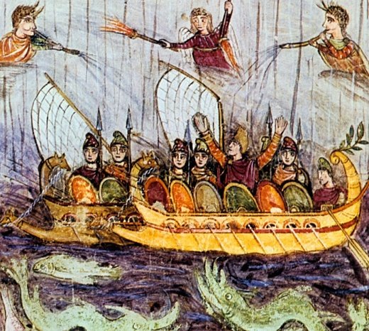
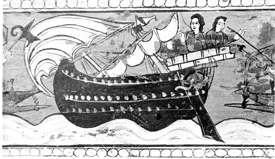
Here are two illustrations of the diagonal support for a spur: one from the fifth century AD Aenid of Vergil in the Vatican Library (Cod. Lat. Vat. 3867, fol. 77r). The spurs on the two galleys are definitely above water level, and each is supported by what appears to be a rope running from the outer end of the spur to a figurehead at the top of the stempost. The other is from a late 13th century painted beam in the Museu Nacional de Arte de Catalunya (catalogue reference 15839). The first image is the far left of the picture, and the spur has unfortunately been cut off - but you can see it on the left hand side of the second image, as well as the spur from a second galley which is shown in full in the third image. The left hand spur seems to be supported by a rope from the stempost, while the right hand spur's support might be a lashing(?), or possibly something more solid. Though both these pictures appear in Age of the Dromon, I have only just (today) obtained high resolution copies, and it is now clear that whatever else the supports are, they don't seem to be chains. In both cases, though their form is different, the head of each spur is at about the same level - approximately half-way between the waterline and the gunwale - the perfect location to smash up oars or the side-rudder. Note that the first picture dates from 5 or 6 centuries before the ship I am modelling, and the second from 2 to 3 centuries after it. Interpolation is always dangerous, particularly as one is from Rome and the other from Spain, but it does suggest that the method of support in these two pictures may have been used in Byzantium through the 10th and 11th centuries. Steven


-
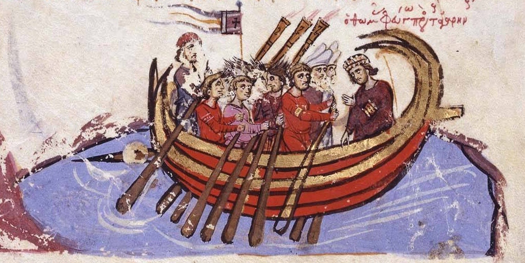
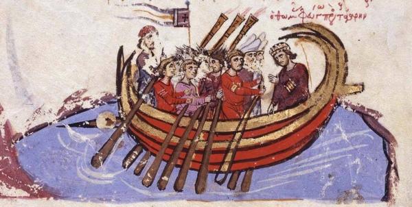
That's one of the main problems I'm up against, Dick. The main strengthening items I see on this are the wales - the gunwale and the two lower wales. As I see it the spur would butt against the stempost and transfer the forces of collision to the wales, which should be strong and flexible enough to cope with them. Because they run fore and aft they should also support the stempost from collapsing backward under the forces. I'd also thought of further transferring the forces from the spur with some sort of diagonal bracing from the spur (maybe halfway along) back to the wales at the cheeks of the bow, but I'm still thinking about that - it may not be practical and there's no contemporary image to support the idea, unlike the chain or whatever that supports it from above. There's no 10th-11th century evidence that the spur was angled upwards - all the evidence for this is from centuries earlier (and of spurs that seem to be built into the hull). 12th century Byzantine, and 12th and 13th century Western illustrations of galleys show them with horizontal spurs . This would transfer the forces of collision in such a way that the spur would be less likely to rotate about the connection point with the hull, which I think is an important consideration. [edit]In his Navmachika Leontos Basilios Emperor Leo VI describes " tag-team" tactics for one dromon to grapple an enemy ship while another rams from the side but Prof Pryor demolishes this as impractical and describes it as "very much like the fireside musings of the Emperor himself". However Prof Pryor cites an illustration in the Madrid copy of John Skylitzes Synopsis Historicon of a direct, side-on collision capsizing an enemy ship. In this case the idea would be to hit her upperworks and even ride up over the hull. [/edit] Otherwise the aim would have been to attack from the stern, to disable the steering oar and the motive oars (and oarsmen). Mark, I'm sure the planking would add to the strength the wales provide - I was pretty impressed with how the planks stiffened the hull as I added them. But I think the wales would be the major factor. The contemporary records make mention of a coupling (katakorax) for the spur, presumably between it and the hull, and I'm working on what form it would take. Steven
-
As I understand it, her crew referred to her as "Eggs and Bacon". You're certainly making very good progress on her. Steven
-
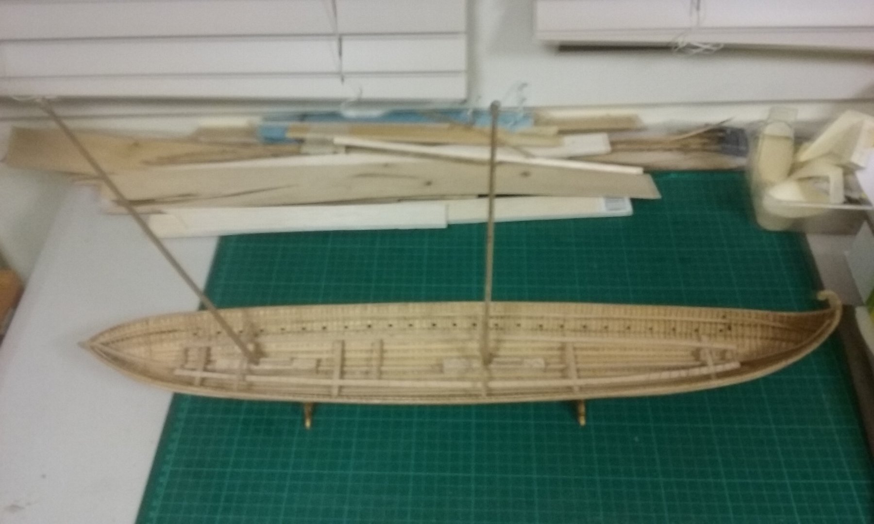
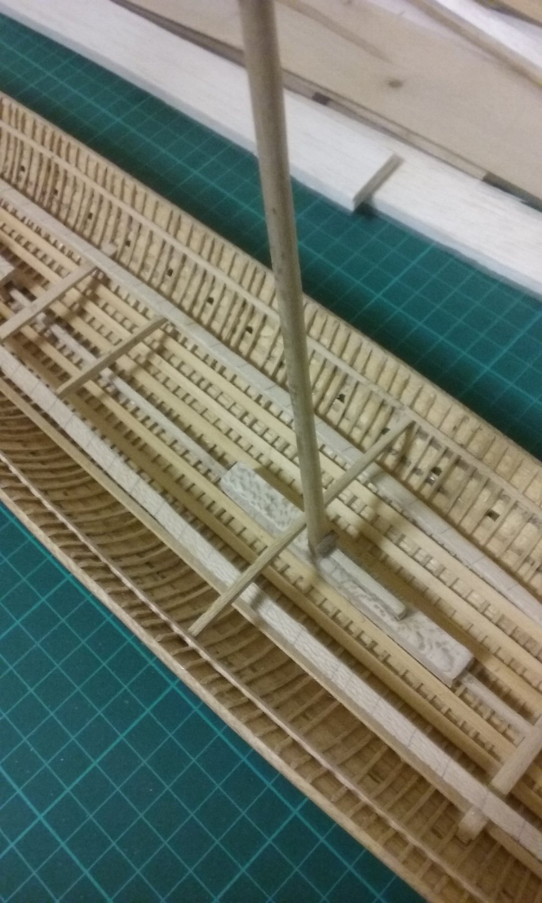
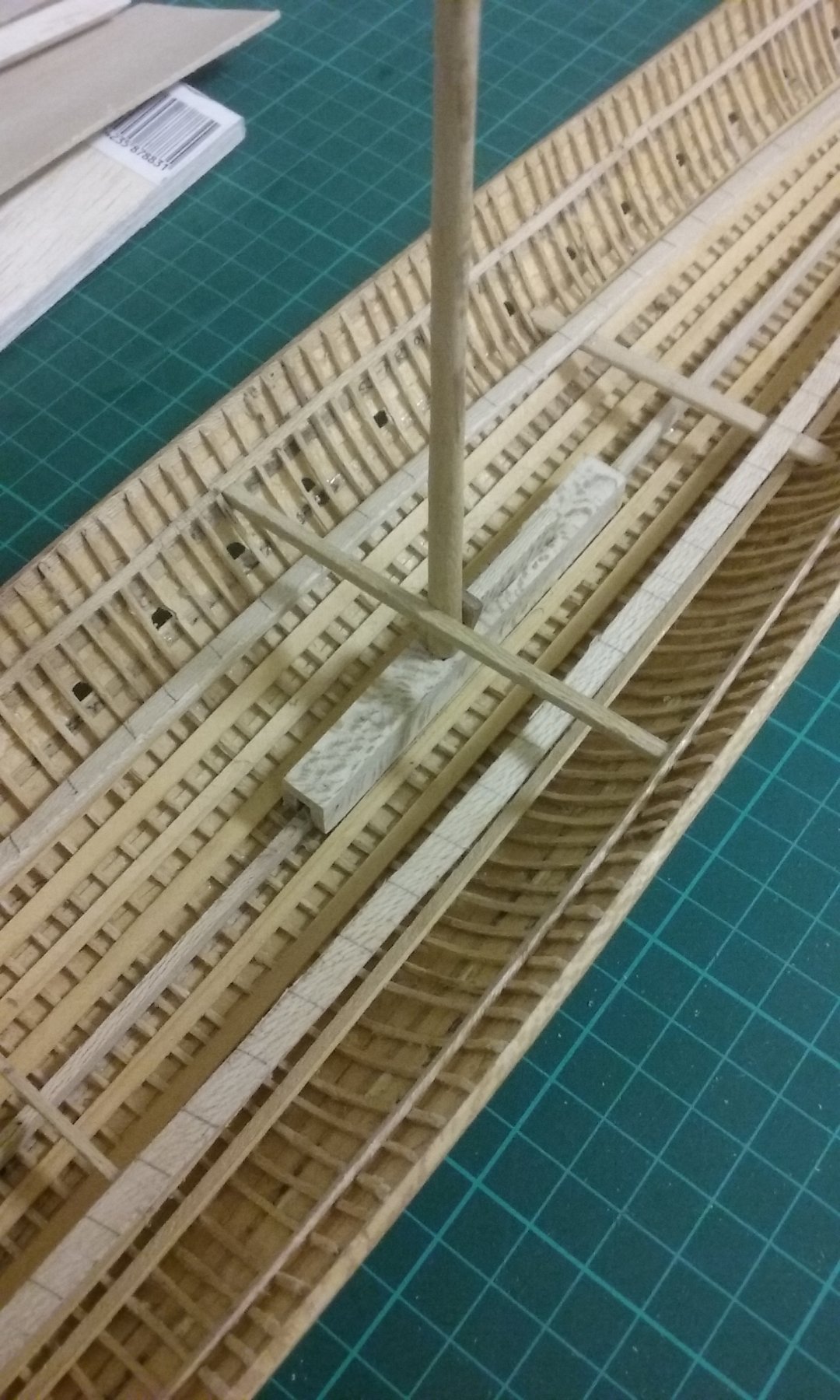
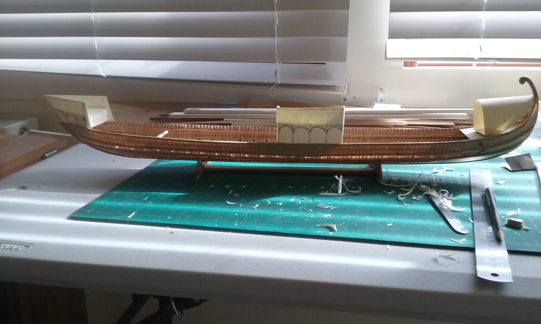
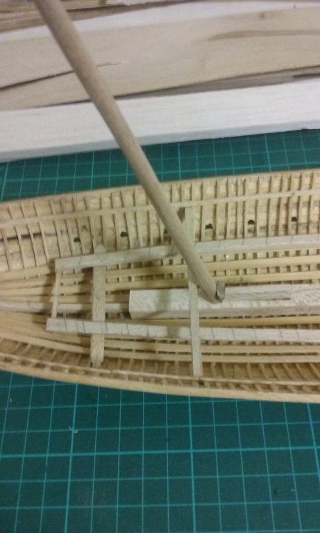
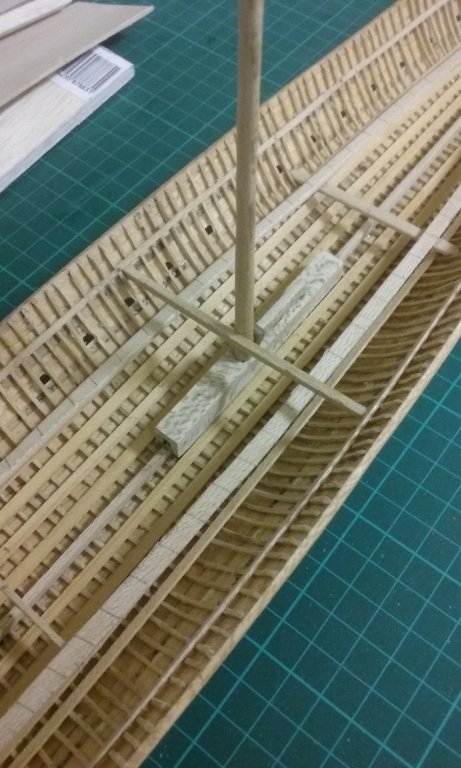
I've now added the mast partners for the fore and middle masts. These are the crossbeams to which the masts are lashed, above the mast step but immediately below deck level, to keep the mast in position. Sorry for the fuzzy photos - taken with my phone at night time - not terribly good lighting. Unfortunately I'd already put the beam shelf in and as the mast partners are fixed to the wales on each side they were a bit too long to fit past the beam shelf. With great trepidation I pulled the sides of the ship apart so the partners could go in. No nasty cracking or snapping sounds, so it was successful. In fact I had to do it about three times with the midmast partner because it was too long even to fit between the wales, so it ended up a little bowed. So I had to cut it shorter and go through the whole nerve-wracking procedure again. It worked, though. So that's all for the masts for the time being. I'm putting them to one side and concentrating on other things. Almost time to do the deck beams. But first I want to tie down the details - and particular the fixing - of the spur. Steven


-
Pat, The local library has "Age of the Galley" and I photocopied the section "From Dromon to Galea" about three years ago - in fact it was what inspired me to begin this build! Looking back at this quote I see that the original Greek passage says "Moreover, hides should be fastened to them [the dromons] against the ram [spur] of the enemy, so that the iron glances off in reaction and does not take hold . . ." I'd argue against the whole spur being made out of iron. First, making something seven metres long entirely out of iron could be done, but would be very difficult with the technology of the time, and anyway it isn't necessary - an oak spur, sheathed with iron would be considerably stronger. Wrought iron, made by hand, would be full of faults and inclusions of slag - the difficulty of making a sword at the time testifies to this. And wrought iron is pretty "bendy" - and far heavier than timber. I wouldn't use it as a spur. It's my belief that the "iron" in the above quote is an iron-sheathed point. A spur would have no need for any more iron than this if you weren't trying to protect the spur from the flames of the siphon. And as only the Byzantines had Greek Fire, enemy ships didn't need to protect their spurs against it. But as the Byzantines did have it, one would expect them to have metal sheathing and perhaps it was iron. It wouldn't have to be strong, just cover the wood of the spur. No, I don't have the MM article but I'd be very grateful for it. I'll PM you. Many thanks. Steven
-
Mark, there are certainly no references to this in the contemporary records, and as far as I can see this was not part of the tactics used. The spur seems to have been used to smash your opponent's oars and preferably steering oar and allow your marines to attack from the relatively unprotected stern, and perhaps even capsize the opposing ship. As usual, most of this is speculation, as contemporary evidence is either lacking or untrustworthy. Steven
-
Thanks Steve, Patrick and Pat. Another reason for the idea of iron plating on the spur is that Prof Pryor mentions a reference in the early 13th century Itinerarium peregrinorum et gesta Ricardi Regis (Itinerary of the pilgrimage and deeds of King Richard) to a (probably Italian) galley with a "rostris ferratis" ["ironed" spur]. (Age of the Dromon, p. 203) However, in this case the iron plating could not have been to protect the spur from the effects of Greek Fire, as this weapon was a closely guarded Byzantine secret. Perhaps it simply means that the spur had an iron point. In the Byzantine case, any metal would have been sufficient to protect the spur, at least temporarily. It would probably come down to which was easiest to get and/or apply. Lead would also be possible, but might be inappropriate because of its weight. Bronze or copper were probably easiest to get hold of and to work, so bronze might well have been used. This is all speculation anyway; we don't know it was done, merely that it would seem to be needed. Steven
-
Pat, I'd appreciate it if you can find it. Carl, I agree. But the Ancient Greeks and Romans used rams, attached directly to the hull which was shaped to receive them. The spur was a separate piece - rather like a knight's lance. The reason I thought of iron is simply that it's less dense, so using iron rather than bronze would probably reduce the weight and thus the leverage of the spur. Steven
-
Just checked again in Age of the Dromon and discovered there's documentation for the 13th century Sicilian galleys having spurs that were 10 metres long and 250mm thick. Presumably Prof Pryor applied his usual 3/4 proportioning between the Sicilian galleys and dromons to come up with the spur length for the dromon. Looks like I'll have to go back to 7 metres - and maybe 200mm thick. But that would be at the base - maybe if I make the spur quite a bit narrower as it approaches the point it will reduce the "tail wagging the dog" effect. Steven
-
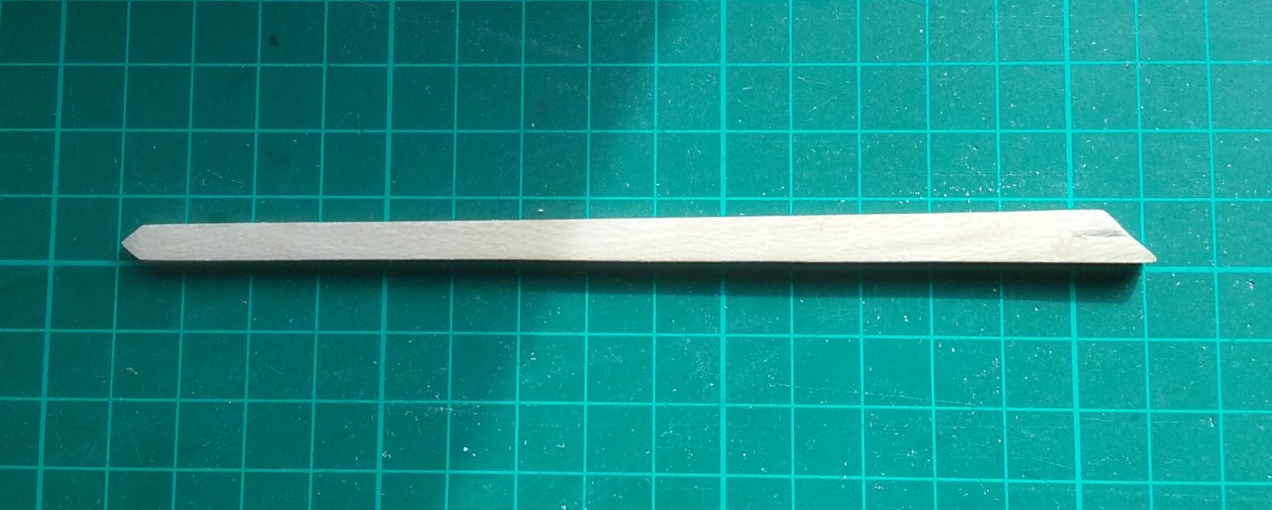
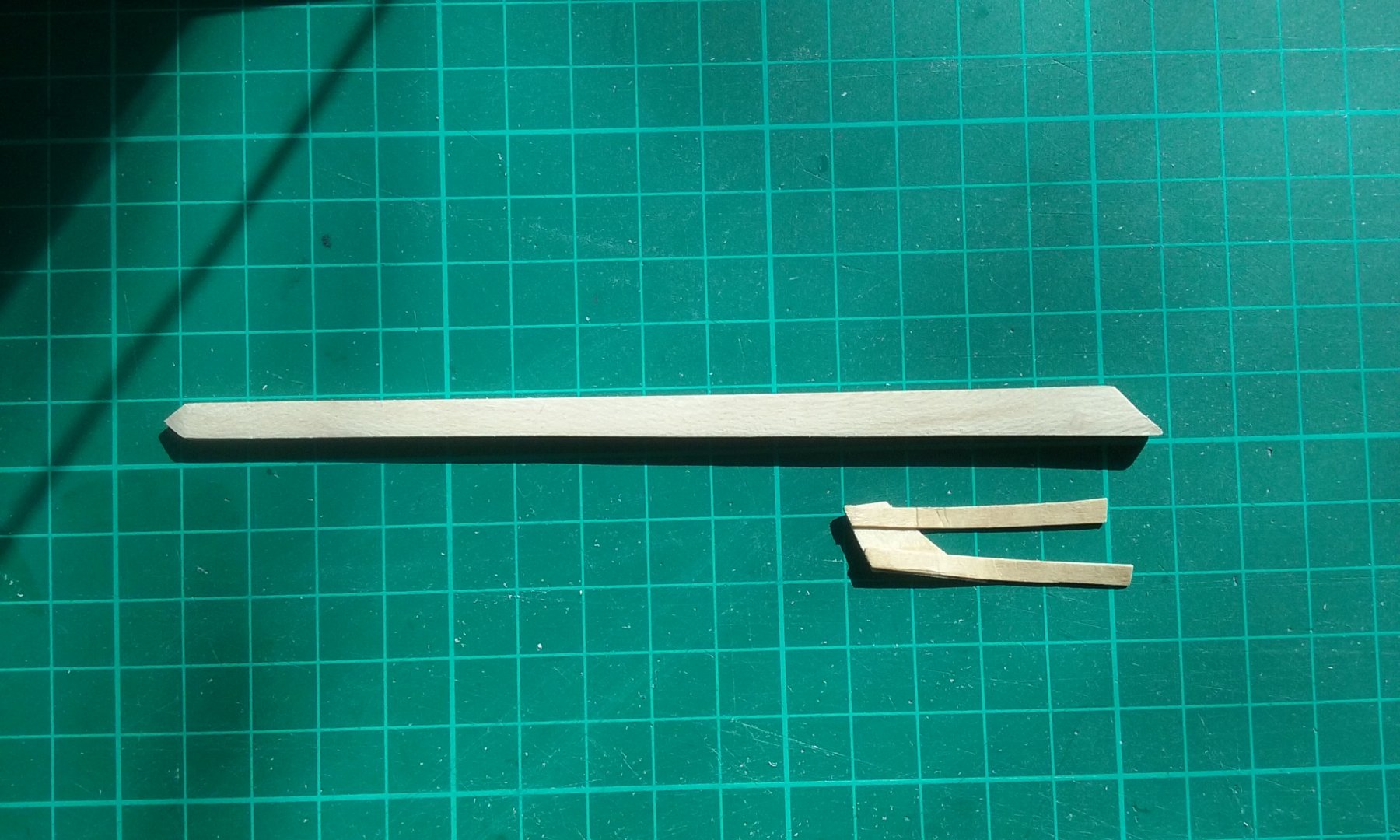
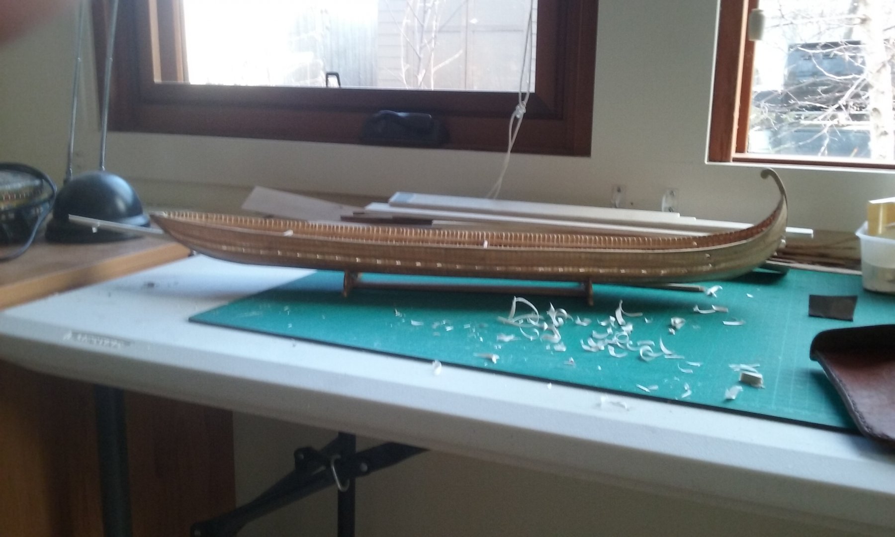
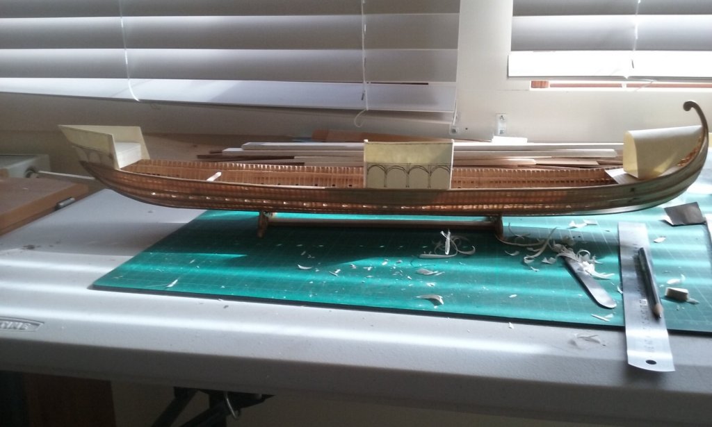
Thanks everybody for all the "likes". Having pretty much sorted out the masts, I'll be putting them to one side till they're needed. There's one more thing still to do, which is install the mast partners, the cross beams that support the masts just below deck level. I'll be posting on that shortly. The next thing to work on is the peronion or "spur", used in ramming enemy ships. Normally one would expect such a thing to be built strongly into the ship's structure as the forces involved in a ramming are pretty extreme, but Age of the Dromon shows that the Byzantine spur was definitely a separate piece, which was then fixed to the ship with a coupling (katakorax). How exactly this is to be done is currently a bit of a problem, as these things would have been pretty heavy and it would be necessary to transmit the forces in a straight line of thrust, rather than at an angle, so as to avoid damage to the ship. Also, sailing in any kind of a sea with one of these things bouncing around, coupled to, but not built into the ship would have imposed all kinds of nasty forces on the bow structure. I have some idea of how to do this, but it's all speculation - we have no idea how it was really achieved, and unless a dromon with peronion attached is found among the Black Sea wrecks, the chances are we'll never know for sure. One thing is that a couple of contemporary pictures, several centuries apart, show a support - perhaps a chain - running diagonally down from the prow supporting the spur near the business end. This would stop the spur from falling too far downward but wouldn't stop it being flung upwards or sideways by the motion of the vessel. Perhaps there were also side chains (or ropes) running back to the cheeks of the bow? If taut enough this could keep the spur pretty much static, much as a martingale boom does for the bowsprit in later ships. The diagram in Age of the Dromon shows the spur as 7 metres (21 feet) long. I made a balsa mock-up and if it's to be strong enough to withstand the shock of collision it seemed much too hefty for a ship this size - and the spur was almost certainly made of oak or some other heavy timber, and possibly metal-sheathed as well (see below). I cut it back to 6 metres 5 metres (oops! lost the photo!) and 4 metres The last two seem to be about the size one would expect, and something like the size shown in contemporary pictures (though these need to be taken with a pinch of salt). This would work better and impose less strenuous forces on the ship's bow. But I'd left out of my calculations the pseudopation (fortified wooden forecastle), which (in my version at least) leans forward at the bow. I think this takes the 4 metre spur out of the running - it wouldn't be far enough forward of the front of the forecastle to engage an enemy ship without a risk of damaging one's own vessel. So maybe 5 or 6 metres, but no more. The other issue is that the spur would be immediately forward and below the siphon - the Greek Fire projector. As it seems to have been pretty much the same as a flame thrower, the chances of flaming liquid landing on the spur would have to be taken into account, so I believe it would have been sheathed in metal, probably iron. It would not have to be very thick sheathing, just enough to keep the spur from catching fire from spills of Greek Fire. So I've got some fun ahead working out exactly how to attach this thing, how long it will be etc etc. Steven


-
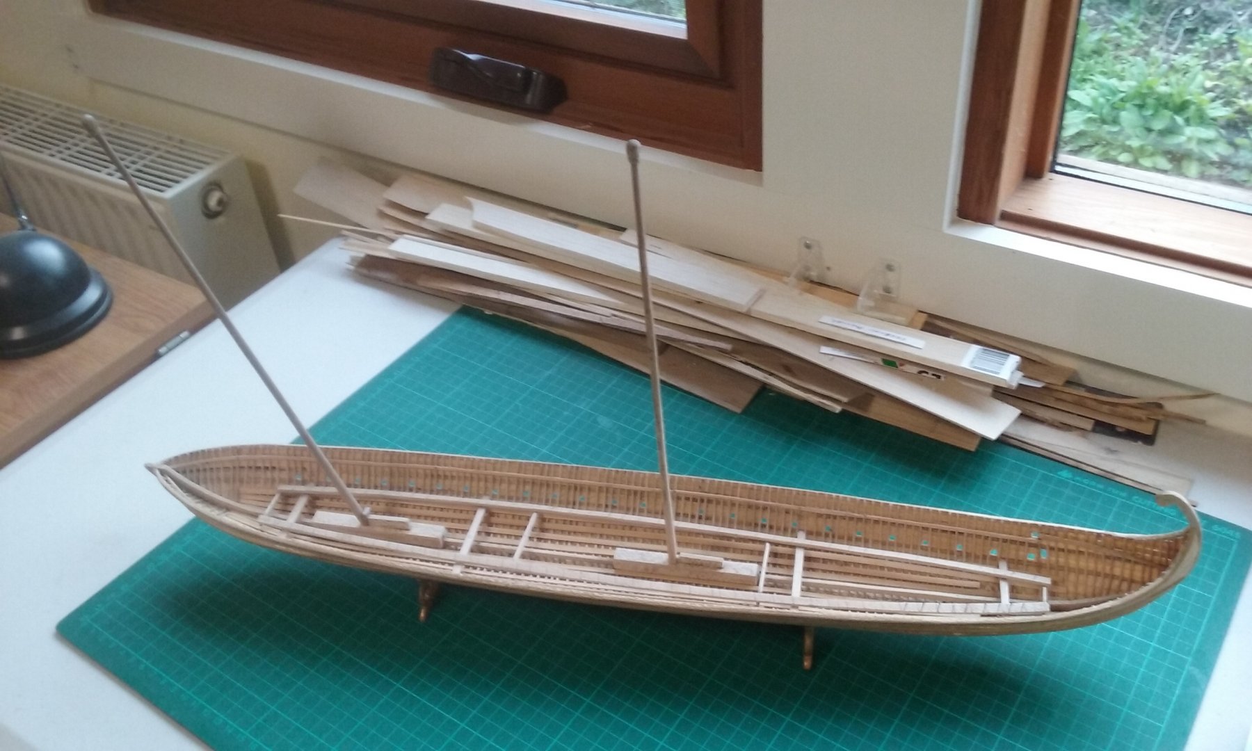
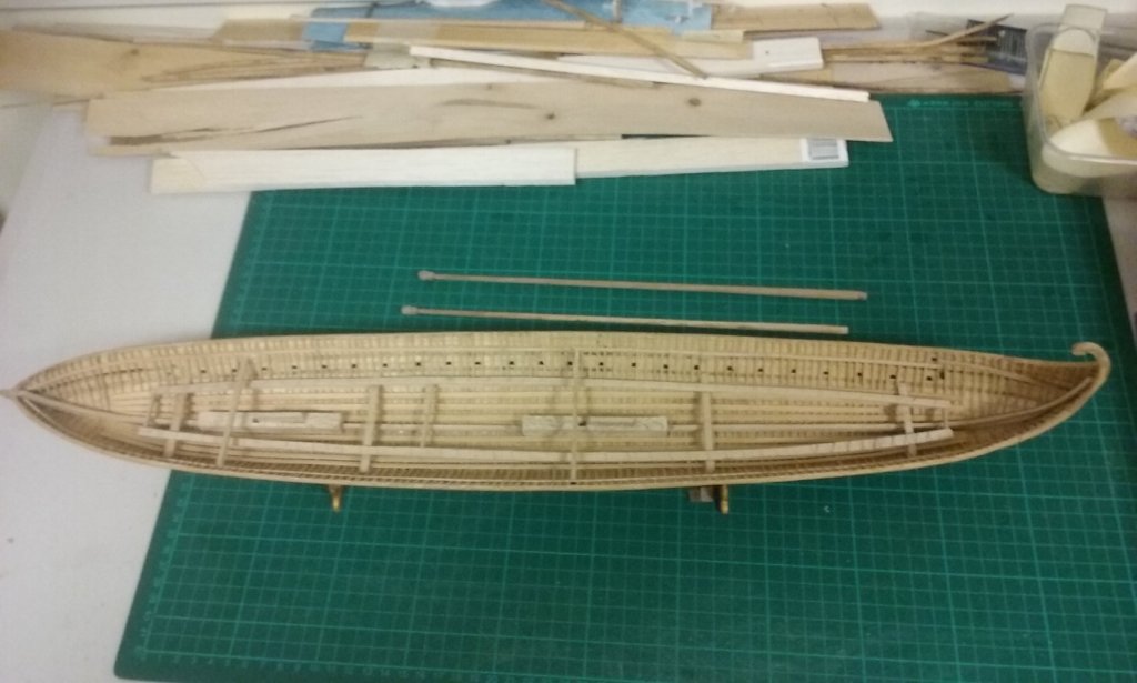
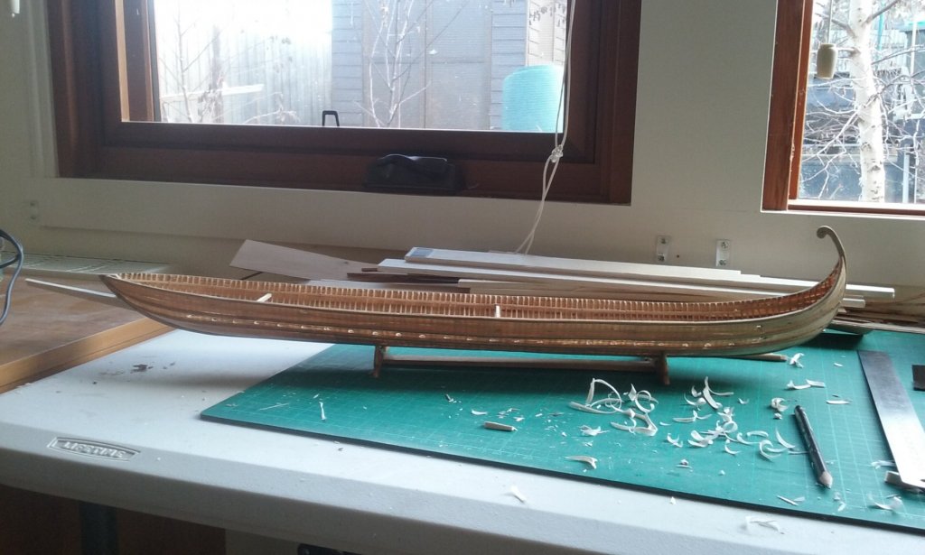
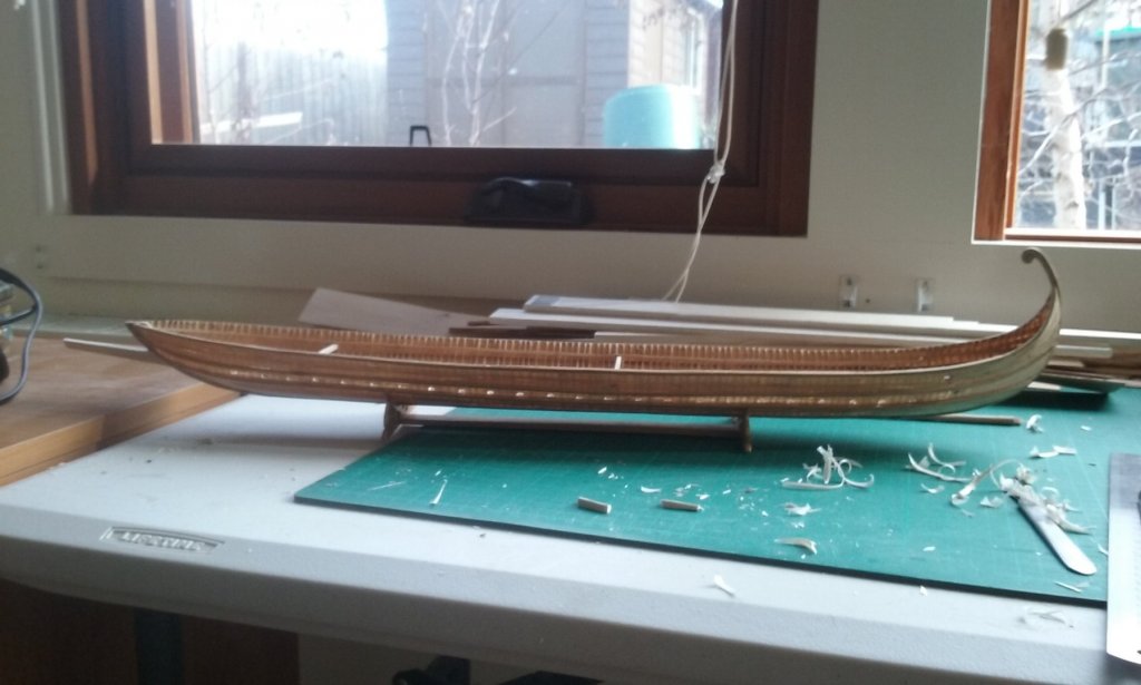
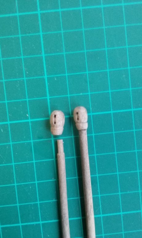
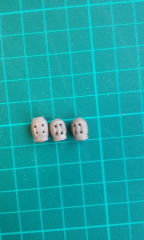
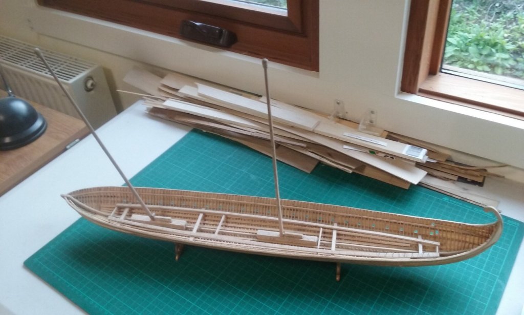
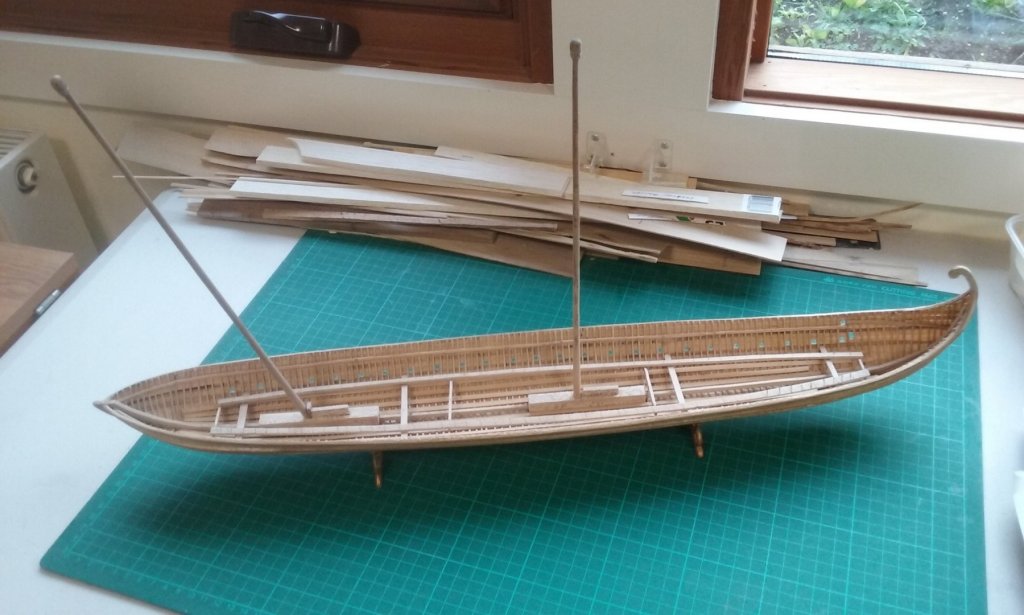
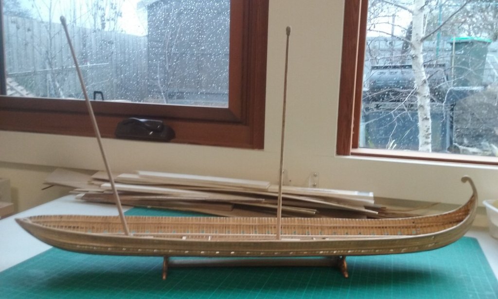
Here are the new calcets (might as well use the name - better than "blob") with a single sheave each. One has already been glued to its mast, the other ready to do so. One advantage of carving them separate from the mast itself is the sheaves can be aligned exactly fore-and aft without having to worry about lining them up with the tenon for the mast-step. And here are the three two-sheave calcets I made while I was waffling making up my mind. One still under construction, to replace one I wasn't happy with, when I changed my mind. And look! Here's another milestone - both masts in place, dry fitted. Starting to look like a ship! From above at various angles . . . shows how the mast angles can fool the eye. The midmast is vertical; the foremast has a rake of 13 degrees. And here she is from the side - with a lovely Ballarat winter's day outside. Steven
-
Dick, this objection would presumably also apply to Prof Pryor's 1984 lateener, but on reflection, if the halyard is belayed to the gunwale I think the yard should slip in between the mast and the halyard so it shouldn't be a problem. On the other hand after a lot of soul searching (and an equal amount of waffle) I've decided to go back to my first thought and have a single fore and aft sheave in the calcet (a name which I discover comes from the word khalkision used in the Byzantine texts on dromons to describe a mast with sheave incorporated in the top). And a pair of single or double-sheaved blocks for the halyard downhaul, leading aft from the mast. Am I right in thinking single-sheaved blocks would not convey any mechanical advantage? Steven
-
That's a very sensible and systematic way of putting frames together to shape the hull. The Venetians were very good at this kind of thing, and your jig looks very good. Steven
- 263 replies
-
- 2
-
-
- nave tonda
- round ship
- (and 2 more)
-
Dick, just checking - Prof Pryor shows the sheaves in the calcet across the ship, not fore and aft? The St Nicholas picture could be interpreted that way, and the Greek Fire could well represent two transverse sheaves. It would mean the halyard would be belayed to the side of the ship, not fore and aft? I think I might do that - it should cancel the problem of chafing. Pat, my reading suggests that not all the oarsmen rowed all the time - sometimes only the forward ones rowed. The Jason Voyage guys certainly did this, rowing in shifts to give each other a break. Again, all the upper oarsmen doubled as soldiers in battle (so the archers were drawn from their ranks), and so there should be plenty of manpower available. And the ship could be kept under way by the lower oarsmen if needed while the sail was raised or lowered. I like your idea of the double sheaved calcet and a single sheaved block. It does seem like a sensible way to go - no need to make raising and lowering the sail any more difficult than it has to be. And certainly, there have been a decent number of blocks discovered in the archaeological finds. Steven