HOLIDAY DONATION DRIVE - SUPPORT MSW - DO YOUR PART TO KEEP THIS GREAT FORUM GOING! (Only 72 donations so far out of 49,000 members - Can we at least get 100? C'mon guys!)
×


Louie da fly
-
Posts
7,989 -
Joined
-
Last visited
Content Type
Profiles
Forums
Gallery
Events
Everything posted by Louie da fly
-
 Getting "water" to look realistic is a very difficult goal. The first photo - the long shot - has a very lifelike look to it, with the blending of the brown at the shoreline. I look forward to seeing your progress on it. It's certainly off to a good start. Steven
 -
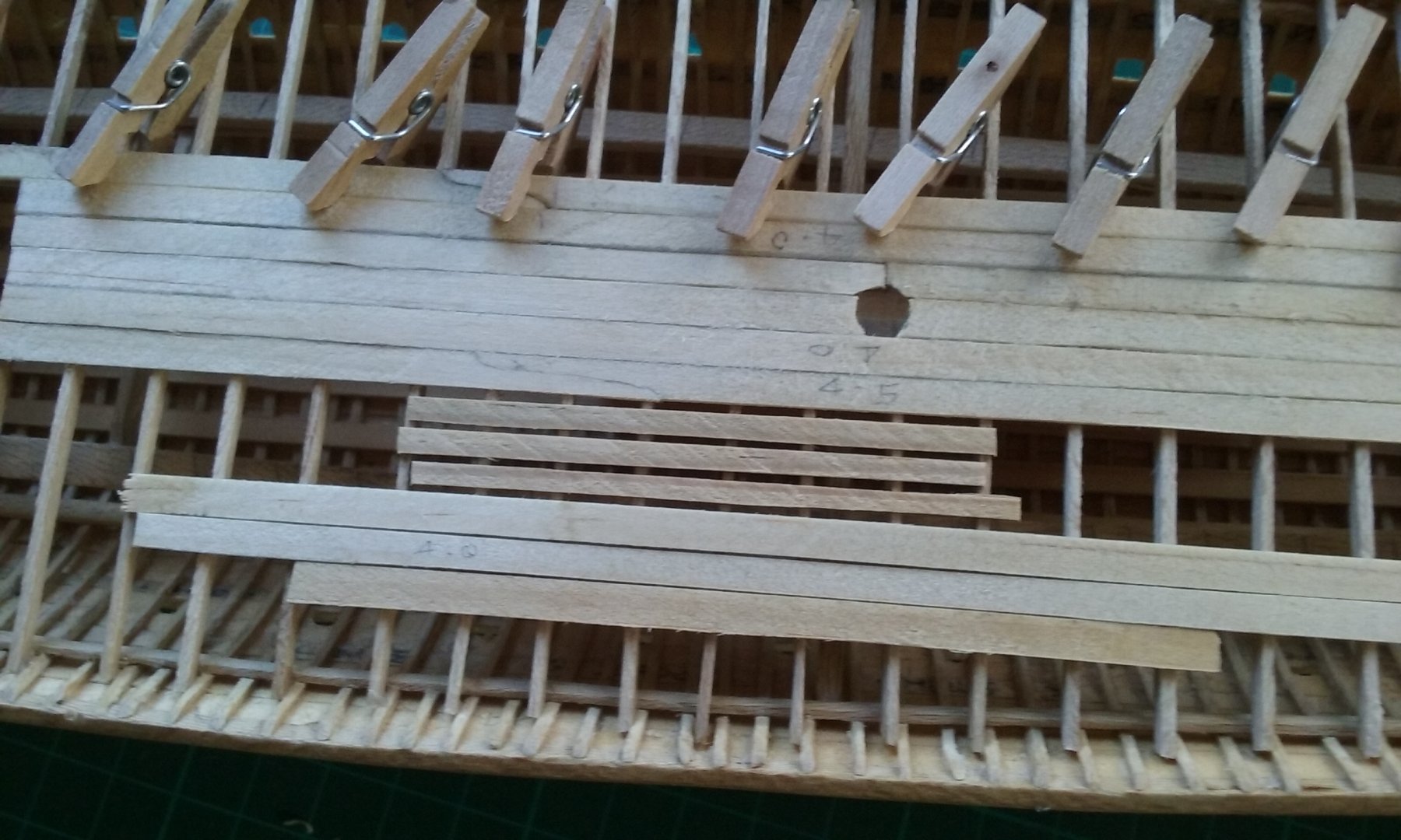
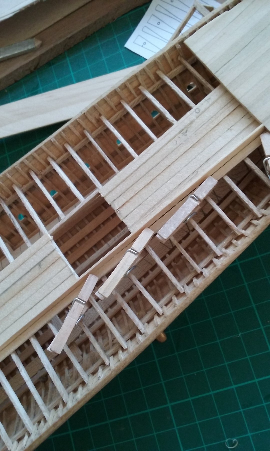
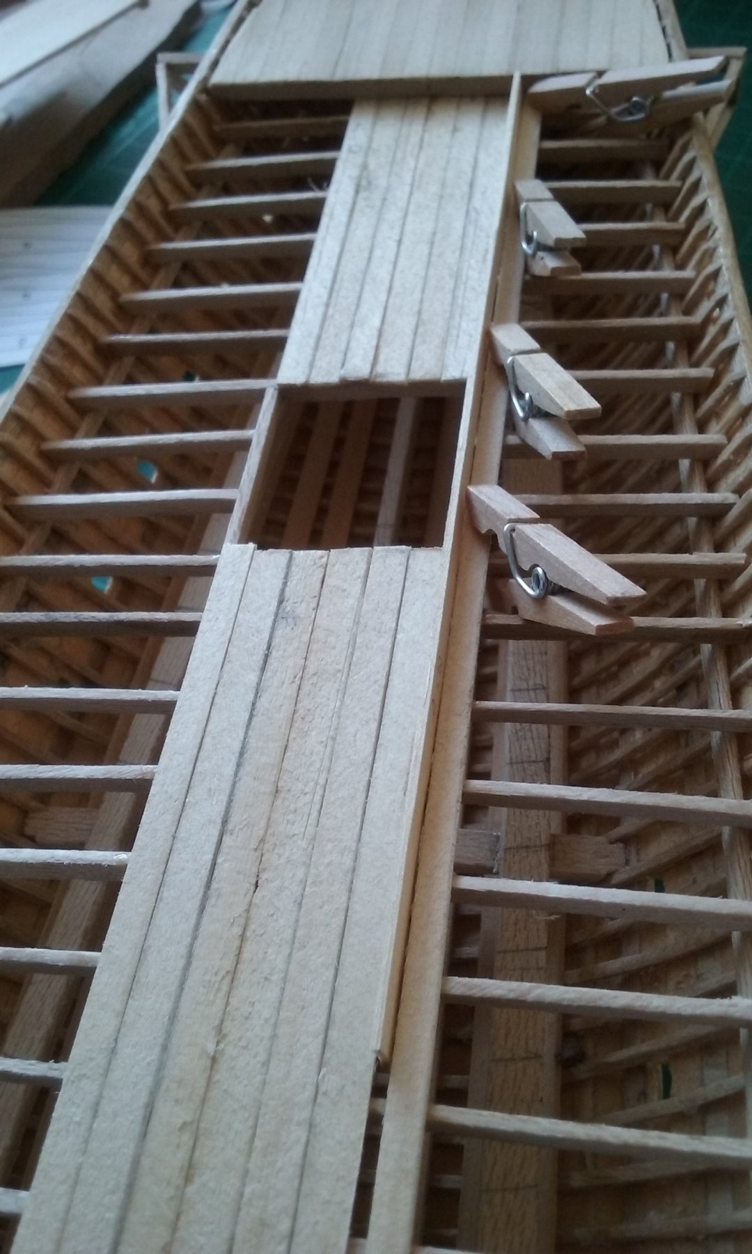
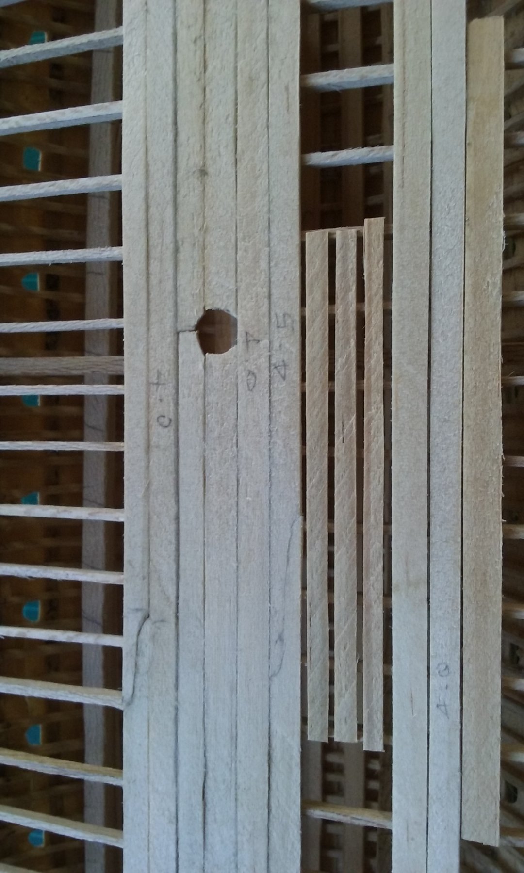
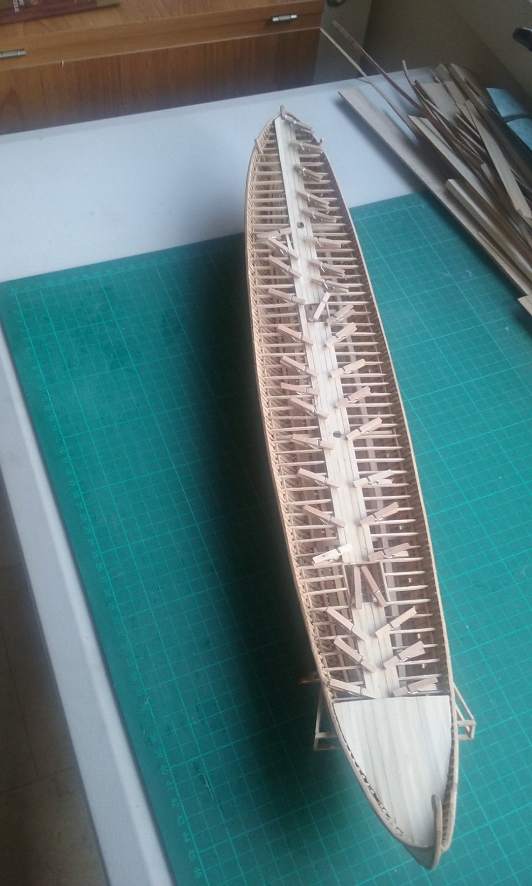
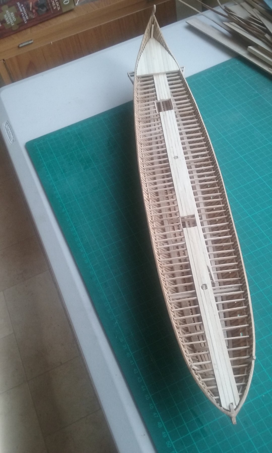
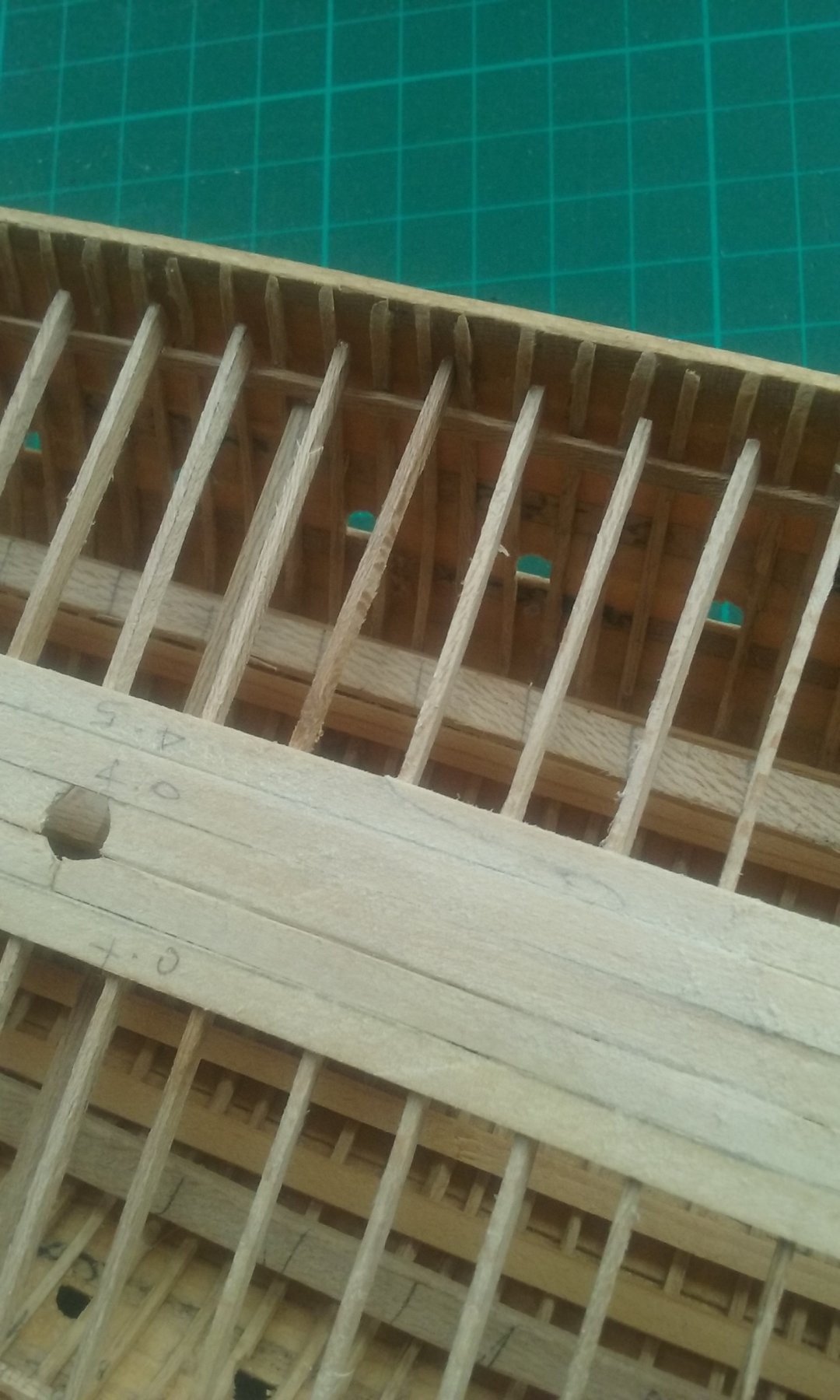
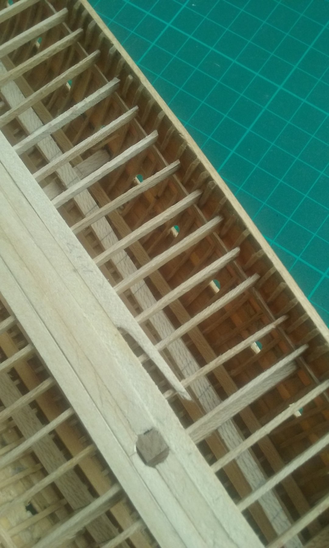
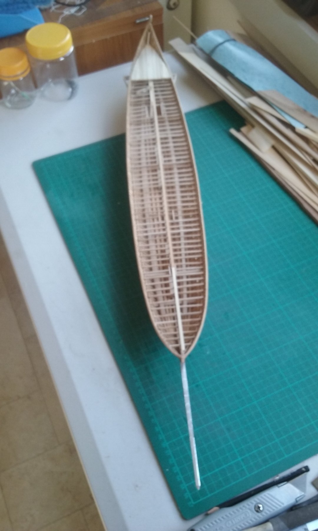
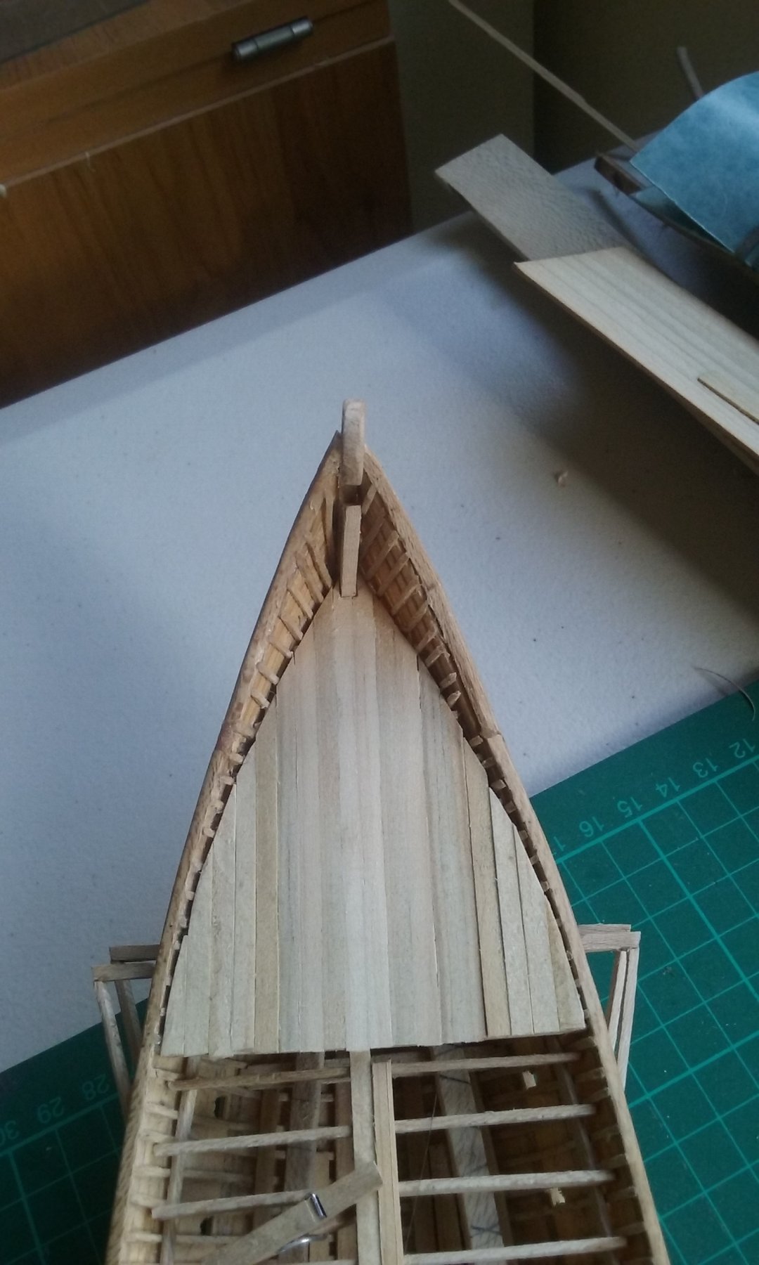
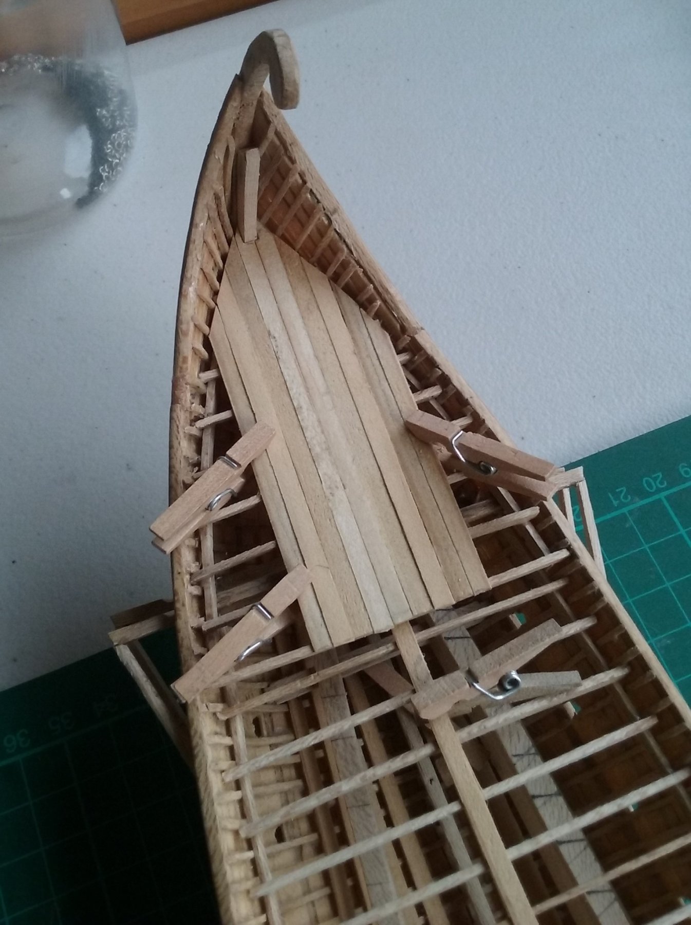
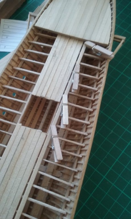
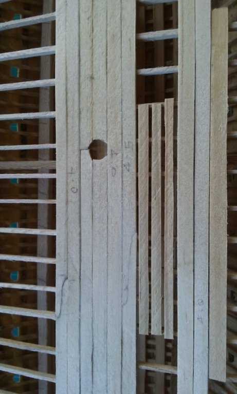
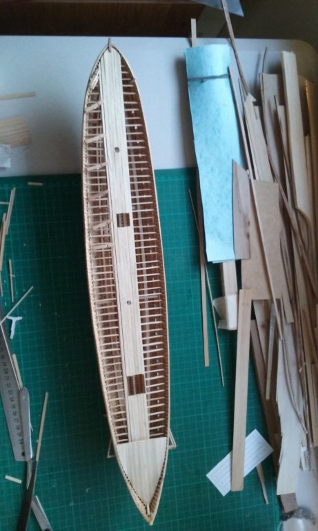
Thanks everybody for all the likes, and Christos and Druxey for the kind comments. The scarph is of course conjectural, based upon the hull planking, because to the best of my knowledge no deck planks have ever been recovered from Byzantine ships. More planking. And now I'm going way out on a theoretical limb, doing something for which there is absolutely no evidence, archaeological or pictorial. But to me it seems necessary. According to Professor John Pryor, the author of Age of the Dromon, a rower needs 0.5 cubic metres of air flow per minute to enable sweat to evaporate sufficiently to keep at peak performance. For a trireme he proposes oarboxes open at the bottom and louvred decks overhead to allow this amount of airflow. Unfortunately, dromons didn't have oarboxes - the lower oars go through the sides of the vessel. Professor Pryor states that the 50 lower deck oarsmen of a dromon would need 4250 cubic metres of airflow per hour with a complete replacement of the air below decks about 30 times an hour. He proposes forced ventilation using "some contrivance such as wind sails or cowls". I've no idea how that would work in a large enough scale to achieve what he suggests. What I decided to do is make openings in the deck above the oarsmen and hope it's enough. I'm putting three deck planks 2.5mm (125mm/5") wide running the full length of the main deck each side of the centre planking, with gaps 1mm wide (50mm/2" in full scale) between them, and on either edge next to the fully planked sections, making 8 gaps in all, providing ventilation for the lower oarsmen. Here's a test run to see how it would look. (In the final form, the fully planked section would also continue to the sides of the ship). And here's the first plank going into place. I used a bit of plank on edge as a guide to form the gaps. The planks are wide enough to give good footing and a 50mm gap is narrow enough not to be a major trip hazard. Though Prof Pryor recommends that the airflow come from below I can't see any way to do this on a dromon. However, as I see it in any sort of a breeze, or even with the dromon on the move, there should be pretty decent airflow from bow to stern and from one side of the vessel to the other. I'd intended to have these openings run only as far as there were oarsmen so the maindeck at the bow would be fully decked. But I couldn't figure out how to make the transition, and the gaps would still have run almost the full length of the deck, so I ran them all the way. I'm aware this presents a risk of flooding in heavy rain, but perhaps they would have covered the gaps with tarpaulins under these circumstances. And in any kind of heavy seas a galley was so vulnerable anyway it would make straight for port, and the extra openings in the deck should make very little difference to its chances of survival in a storm. In any case, that's the best I can come up with to solve the ventilation problem.


-
It goes even further than that. The words Knecht and knight have the same origin, and in England before the Norman Conquest of 1066 a cniht was a servant or henchman. Mounted warriors weren't part of the Anglo-Saxon environment, and for this new idea (probably because these mounted warriors owed service to a Norman lord) they used the word for servant and called them knights. In such countries as Germany and Holland, the word kept its original meaning. As far as I know, English is the only European language that doesn't use a word connected with horses to describe a mounted warrior. Everyone else calls them something that means horseman - caballero, chevalier, ritter, ridder . . . Steven
-
That's the true test of a genuine fan - the bad times, not the good ones. It's easy to be a fan when your team is winning, but to stay faithful when they're losing time after time, and keep the faith no matter what, that's what it's really all about. I support (naturally enough) the West Coast Eagles. We do ok, but it's a long time since we won a Premiership. Steven
-
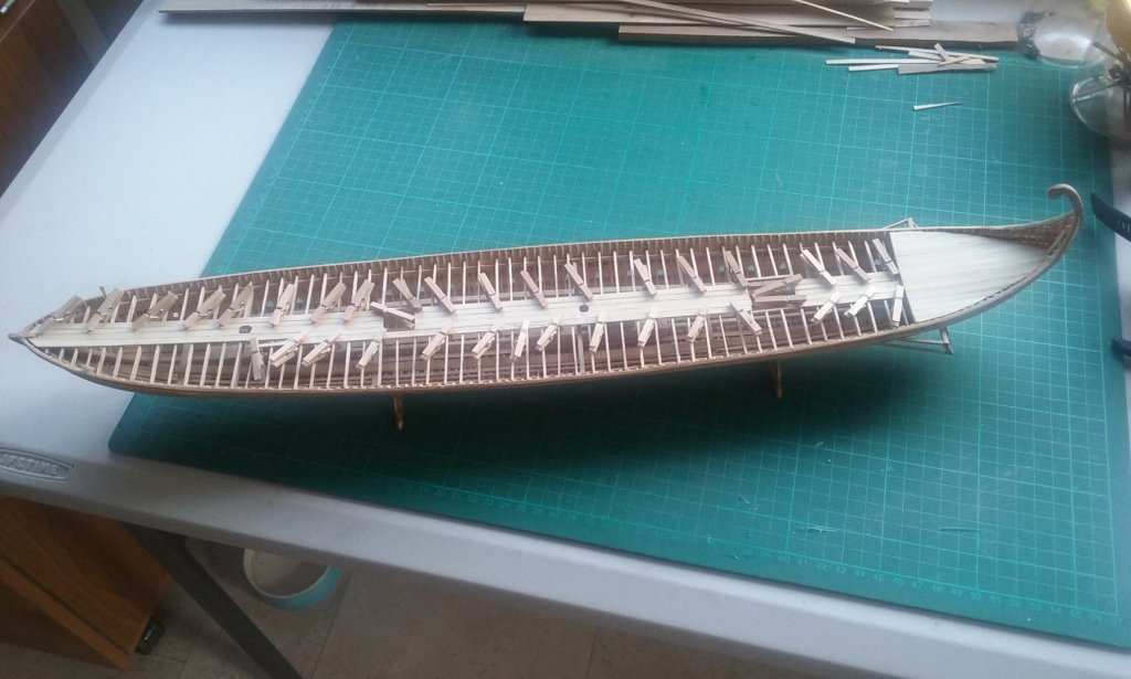
More planking: As the planks are now out past the opening for the companionway, they have a longer run. So I've put in scarph joints similar to those on the strakes. I faked the first one - I just cut the plank into two lengths with a curved line and glued it back together. But the second one is the real thing. Adding yet more planks, including completing the scarph joint: And I've made a start on the anchors. Photocopied to scale and glued to a 1mm thick sheet of brass. And cut roughly to shape. Next thing to do is file it to shape, except where I'll be leaving it a bit wide where the real anchors are a little thicker, so I can bash it a bit sideways to make it more than 1mm thick at those points.


-
Hmm, I think I can call myself an Aussie Rules fan, but as I'm a sandgroper and came to Victoria late in life I'm not sure I get the reference - unless it's the grandstand railings at Brunswick St Oval? Steven
-
Looking very good, Chris. So many railings - you have amazing patience. Steven
-
Well, I'm even more impressed. You've produced a beautiful model without the benefit of formal plans. My hat's off to you. Your figurehead is looking good, too. You've made a good beginning - keep at it. I'm looking forward to seeing how it turns out. Steven
-
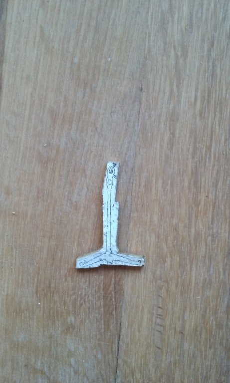
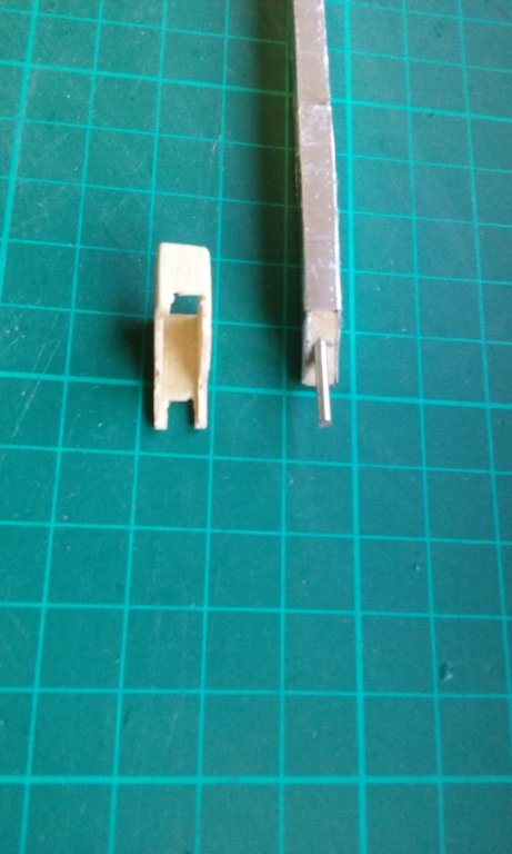
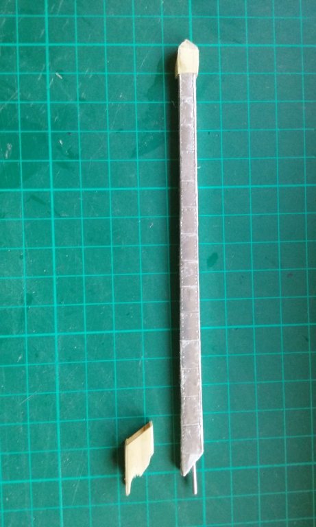
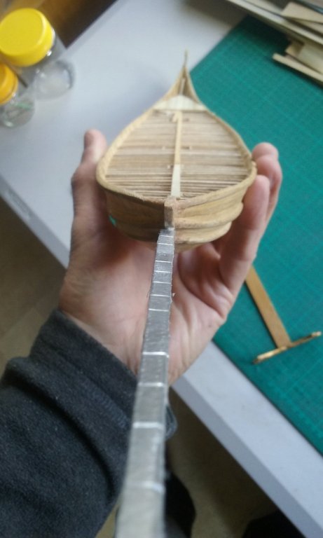
More deck planking. I'm following Druxey's suggestion to have the planks different widths. It doesn't look all that different (widths vary from 3.5 to 5mm), but it's closer to the likely reality. The socket for the spur. I've made it out of pine, and will smooth it off and paint it to resemble iron. I've had to cut it away in places to allow for the stempost and the wales. There also will be reinforcements to the socket following the line of the wales, perhaps to be made of wood, but painted to resemble iron. I've also made a trial piece for the iron-shod head of the spur. Not very happy with it. I'm thinking of doing it in aluminium sheet instead, because wood really doesn't do the job or look good. Steven
-
A beautiful restoration, performed with admirable persistence, attention to detail and refusal to accept second best. I take my hat off to you, sir. Steven
- 749 replies
-
- 6
-

-
- albertic
- ocean liner
- (and 2 more)
-
How did I miss this wonderful build? Beautiful work throughout Christos, and those sails are a real treat! Steven
-
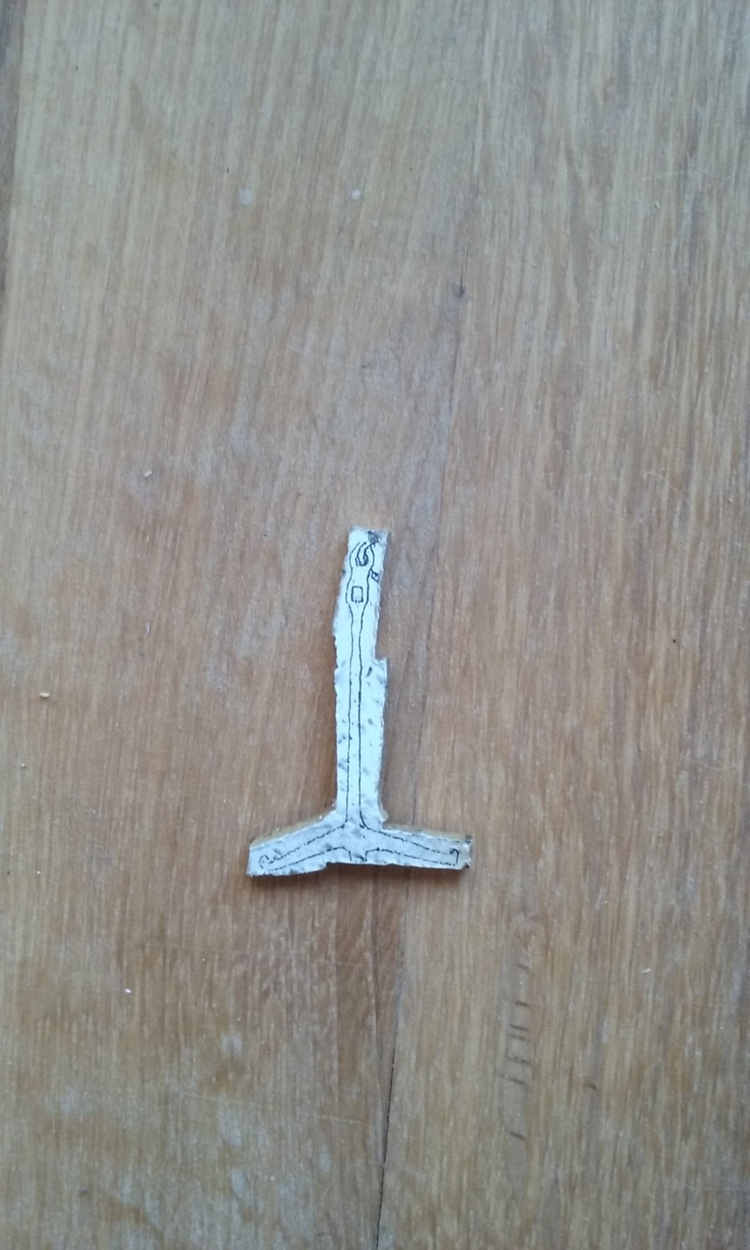
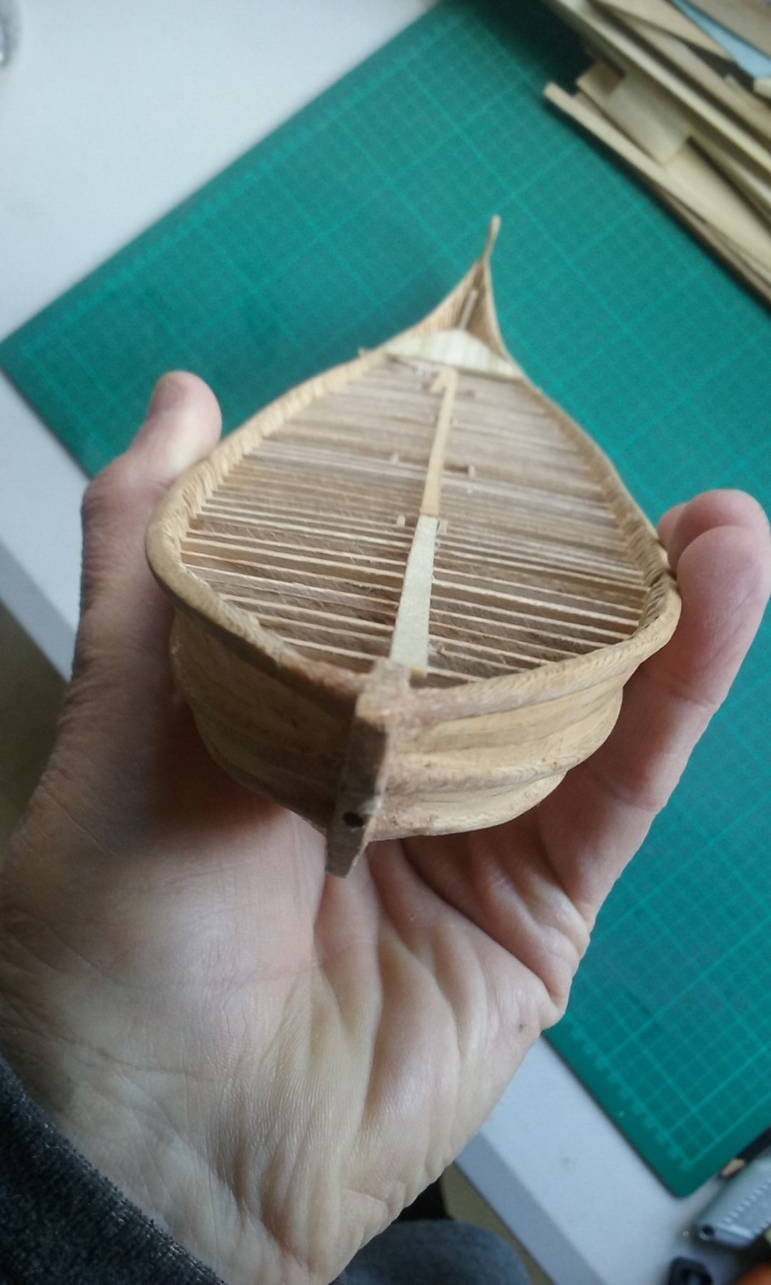
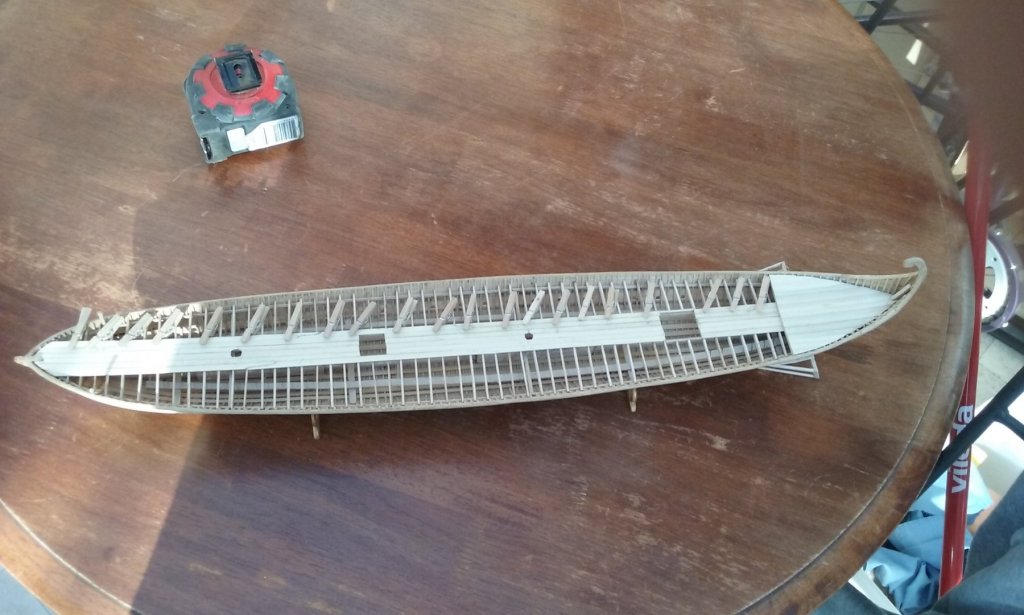
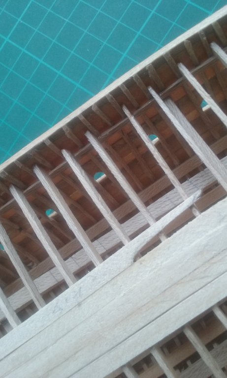
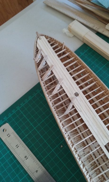
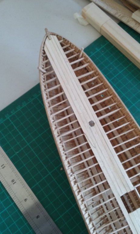
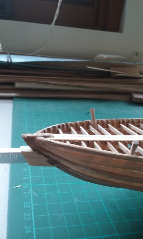
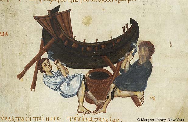
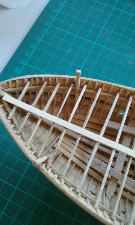
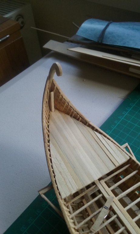
According to Age of the Dromon: ". . . there were also periboloi on either side at the prow, from which the anchors were lowered. Periboloi were also listed in the inventories for the Cretan expedition of 949 . . . Our best suggestion for the meaning of peribolos is “cathead”. On Greek triereis the epotides, the transverse “cheek timbers” of the outriggers at the bows, had apparently served for this purpose; however, with their passing something like catheads must have become necessary on galleys. Other ships of any size must always have had something like catheads. Leo VI . . . said that it was the duty of one of the two oarsmen at the bow to cast, (ballein), the anchors into the sea." In this picture there are two vertical pieces of wood at the bow which I believe are the periboloi. Not catheads as such, but performing a similar function. The anchor cables would have run around these, leading thence to the windlass at the break of the forecastle. And here's my interpretation of them: The edges are rounded to minimise chafing, and they are fixed to the beam shelf and, at the bottom, to the nearest frame. Steven
-
You could be right, Druxey. None of the Yenikapi galleys had deck planks because they were only single-banked. The archaeological drawing of YK4 has hull planking widths which do vary somewhat, from about 350 to 500mm. However, the wider planks are closest to the keel, and it's a bit hard to tell whether the variation is real or an illusion caused by looking straight down on the curve of the hull at the turn of the bilge. I don't know that there is any particular reason the deck planks should all be the same width, but I'll think about it. Steven
-
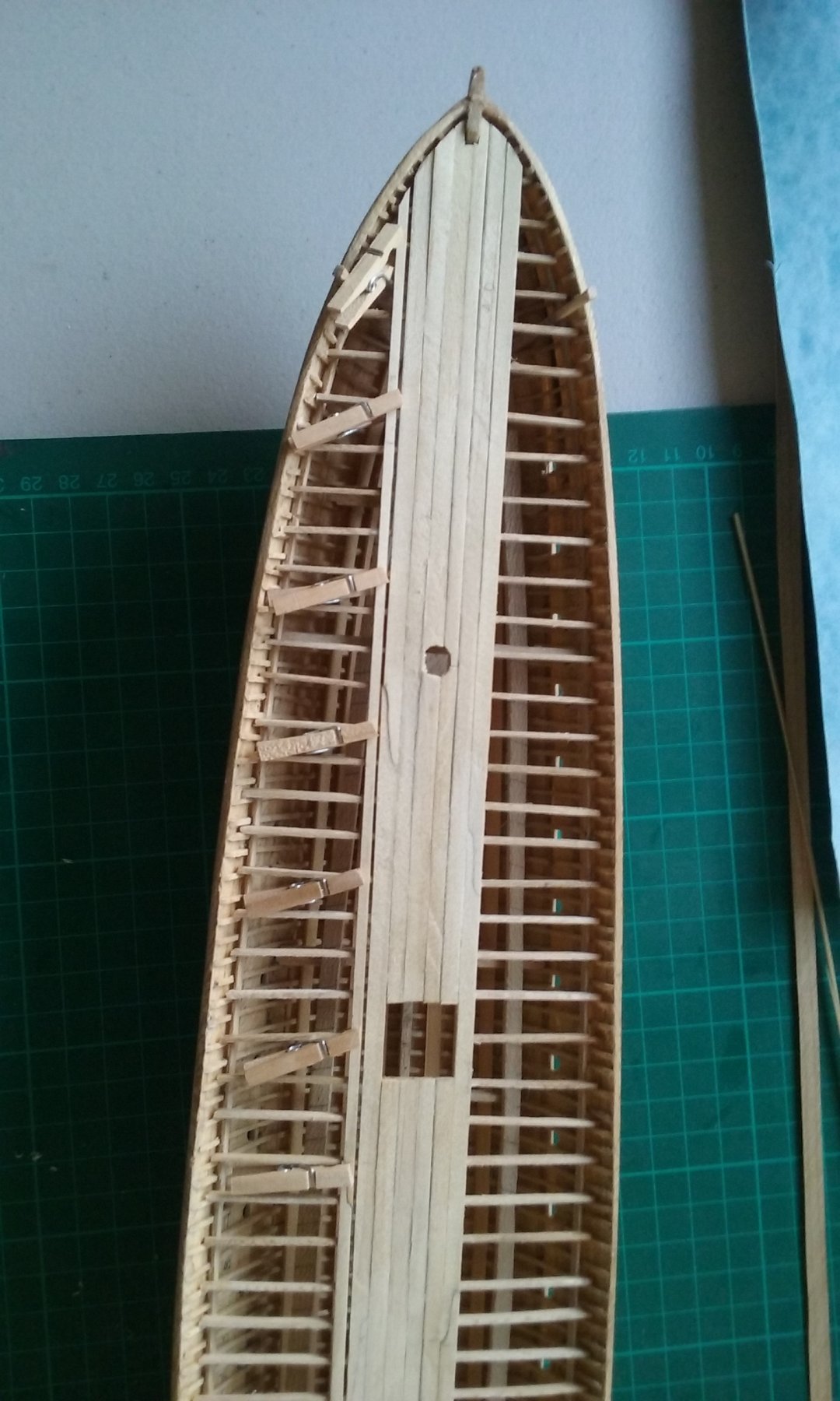
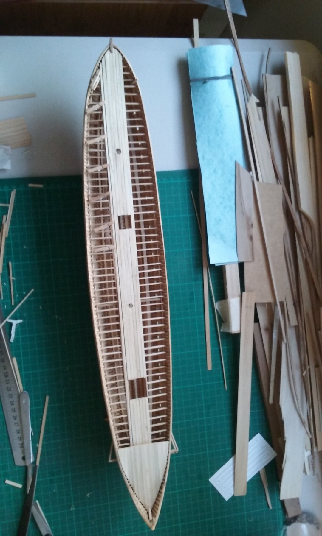
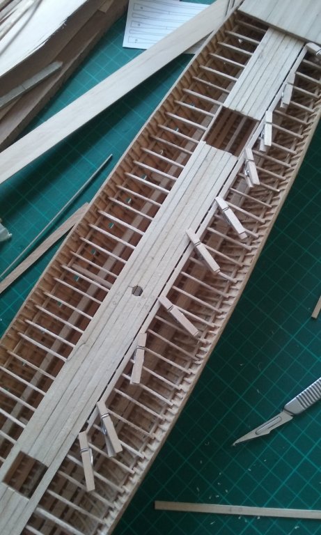
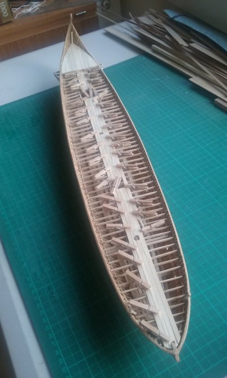
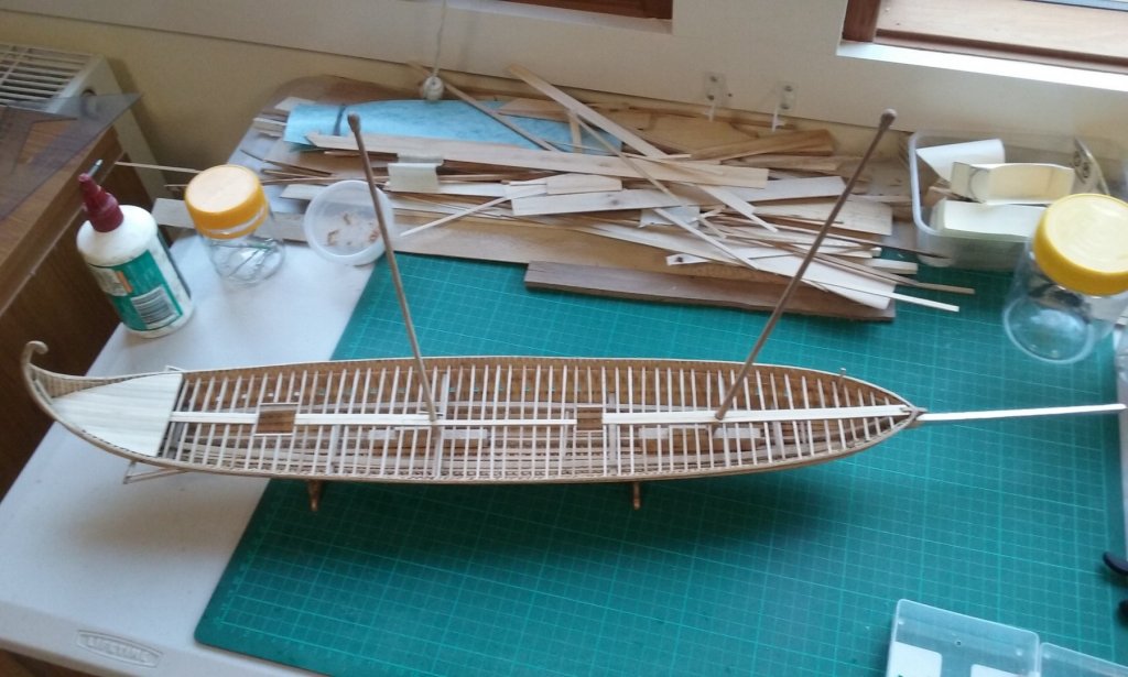
First deck planking. Beginning the decking on the prymne. Also I've run a temporary batten tacked in place with a few spots of glue, with one edge running along the centre line of the ship to fix the run of the main deck planks. And I've completed the plating on the spur. Prymne decking complete and partly sanded. One plank has been glued next to the batten between the break of the poop and the hatch; once all that line of planks are in place the batten will be removed. I still have to complete the sanding on the prymne and cut off the planks in a straight line at the break of the poop. And then get onto the main planking in earnest. (It's important to be Earnest - ask Oscar Wilde) Steven


-
Thanks, Druxey. I was really just after a ball-park sort of figure, and what you've provided is very helpful. The TAMU paper I have contains some archaeological finds of links which I'll also have another look at, though if I remember correctly they're from several centuries too late. Still, any information that helps me to a decision is worthwhile. A dromon with a crew of over 100 shouldn't have too much of a problem finding enough men to man the pumps. They weren't always rowing and even when they were, much of the time not all the oars were in use. Steven
- 12 replies
-
- 1
-
-
- chain pumps
- dromons
- (and 2 more)
-
She's looking good, John. I've been enjoying following this log - very interesting, particularly from a research point of view, and the personal connection adds to the interest even further. Hope the health problems get sorted out and you'll be free to get back and enjoy yourself to the fullest with the build. Steven
-
HMCSS Victoria 1855 by BANYAN - 1:72
Louie da fly replied to BANYAN's topic in - Build logs for subjects built 1851 - 1900
Can you still get that stuff? I used it for the sails of my Great Harry model way back in the 60's, but I thought it had vanished off the face of the earth. I have to warn you, however, that my sails went all brown and brittle over the decades, but that may have been the mistreatment and neglect after I stuffed the part-demolished model in a cardboard box and left it for about 40 years. (I'd intended to fix it all up, but moved states, changed jobs and repeatedly changed address and got on with other things in life. I still intend to fix it up after the current build and I'll probably do a better job now than I would have then). Steven- 1,013 replies
-
- 4
-
-
- gun dispatch vessel
- victoria
- (and 2 more)
-
Another question - does anyone know how big the top cogwheels of the chain pump were/should be? Is there a sort of standard size, or does it vary with the size of ship? And if it varies, how big should they be for a dromon - a ship 30 metres (90 feet) long that is long and narrow? Rough estimates totally acceptable. I just want to get an idea of the size I should be looking at for my chain pumps, because currently I have no idea at all except for trying to estimate it from looking at pictures of them on models. Thanks in advance, Steven
- 12 replies
-
- 1
-
-
- chain pumps
- dromons
- (and 2 more)
-
Hi, Lin. The Trincomalee is a very worthwhile model to make and you're doing a very good job on her. I've always wanted to do one of HMS Shannon, which was pretty much a sister ship of the Trincomalee. Just a question - did you have already existing plans to work from or did you draft them yourself? I don't consider myself an expert carver (there are much better ones on this forum alone), but you might like to look at page 7 of my own build log (near the bottom of the page) going from blocks of wood to finished figures. I use pear wood as it has a nice tight grain. I concur with Druxey's points: *Making a plasticiene test piece works very well, particularly with a difficultly shaped figure. I cut a rectangular section block of wood to start with, so I can draw on all four faces if I need to. *I make the block about twice the length of the figure so I have something to hold onto while I'm carving. This is a variant on Druxey's idea but works the same. I cut the piece roughly to shape with a coping saw, then remove unwanted wood with a Stanley knife, then for fine detail move on to a scalpel with a No. 11 blade (you can buy them from some chemists or medical suppliers, along with the proper scalpel handle) - I don't like the "craft knives with a similar blade - I find the blade always seems to come unscrewed at the worst possible moment. I cut away in "layers" - leaving the highest profile bits in place and cutting away deeper and deeper as appropriate to the specific part of the figure. The absence of bloodstains on the figure indicates you're probably already careful with sharp blades, but care is vital. Also use Youtube. There are some very good videos out there which are well worth watching. Have fun with it. Steven
-
Different artistic conventions. I believe the "big" eye was the way things were done (look at the eyes on Greek galleys) though our own sensibilities seem to demand something a little more subtle. Steven
-
Nice work, Patrick. And an ingenious solution for the rudder attachment. A very enjoyable build to follow. Steven
- 756 replies
-
- 4
-
-
- galleon
- golden hind
- (and 2 more)
-
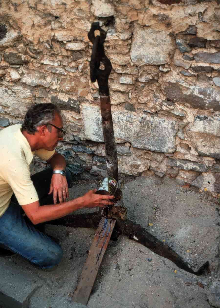
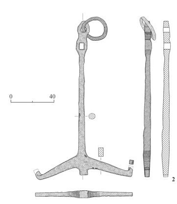
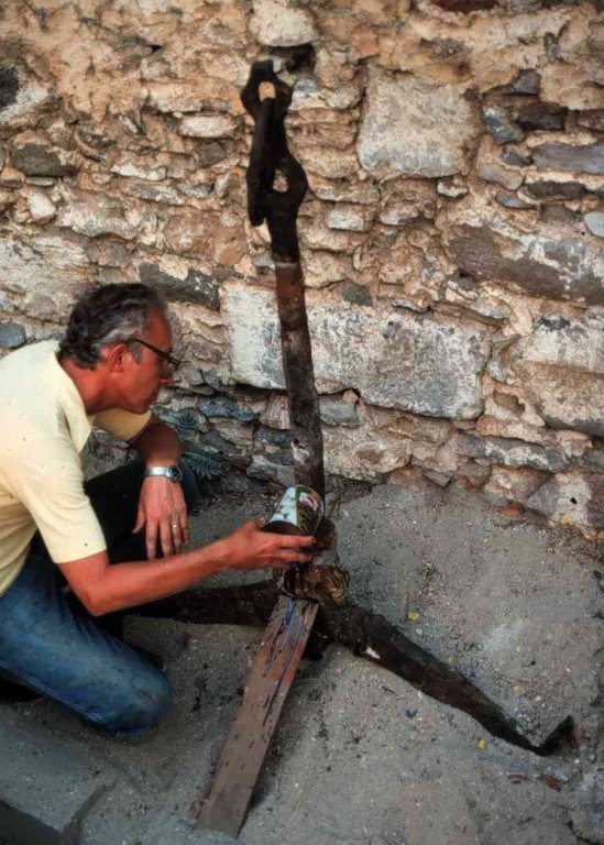
Thanks everybody for all the likes and the kind comments. Don, just tried it. Through the cargo hatch no worries (you have to slide the oar through the hatch at a small angle above the horizontal - and have someone below decks to receive it), a rather tighter squeeze through the companionway, but it can just be done. I'm now finishing the plating on the spur and also just beginning at least part of the deck planking. Other projects I'm looking at are getting under way on the yards and making the anchors. Here are pictures of the anchor from the contemporaneous Byzantine Serce Limani ship. Judging by the size compared to a human the scale is presumably in centimetres. The anchor in 1:50 scale is just over 1mm thick at its thickest point and I'll be making them in 1mm sheet brass and then colouring them to look like iron. I have a cunning plan to get that extra bit of thickness in the brass where it matters - cutting the shank a little too wide and then annealing and belting it with a hammer so it gets narrower and thicker. Should be fun. Steven
-
Yes, I'm afraid it is - see post #271 on page 10 of this thread to see why. I finally decided I'd have to accept the slight out-of-squareness after my repairs, because it would have required just too much extra work to correct. I decided I'd just have to put it down to experience, and I'll know more for the next build. Steven