HOLIDAY DONATION DRIVE - SUPPORT MSW - DO YOUR PART TO KEEP THIS GREAT FORUM GOING! (Only 72 donations so far out of 49,000 members - Can we at least get 100? C'mon guys!)
×


Louie da fly
-
Posts
7,989 -
Joined
-
Last visited
Content Type
Profiles
Forums
Gallery
Events
Everything posted by Louie da fly
-
 As I understand it, her crew referred to her as "Eggs and Bacon". You're certainly making very good progress on her. Steven
 -
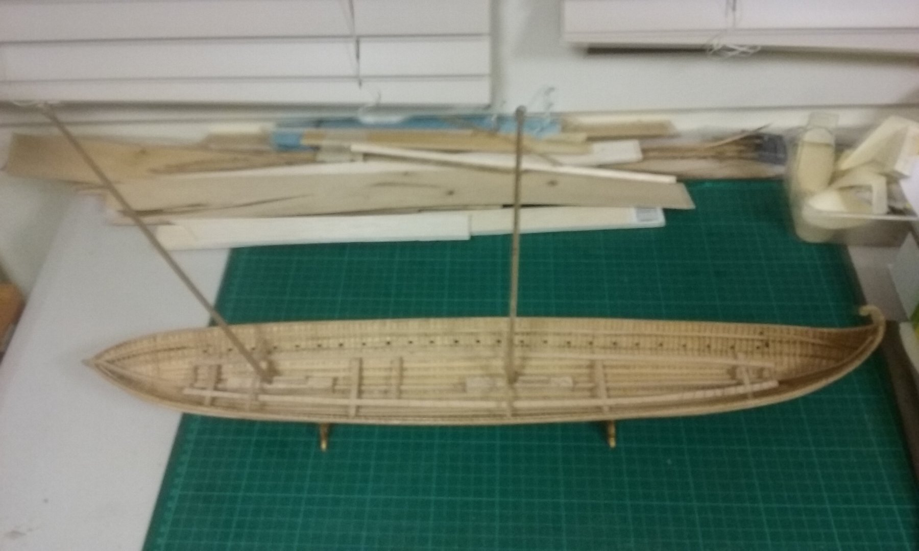
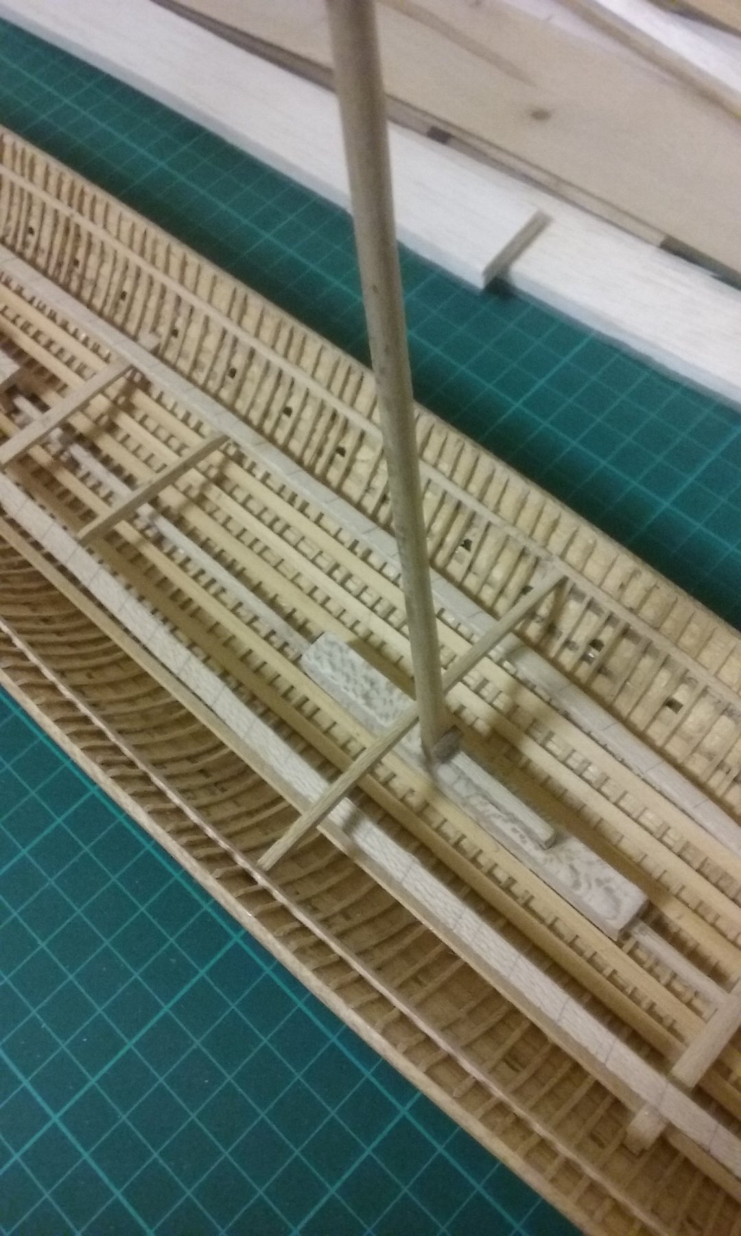
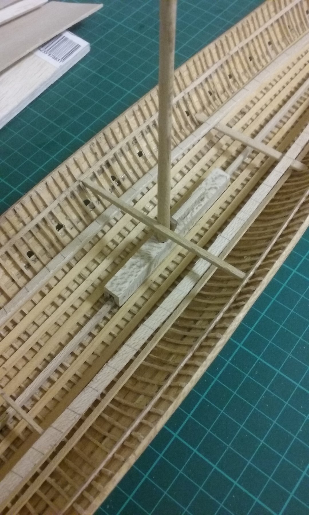
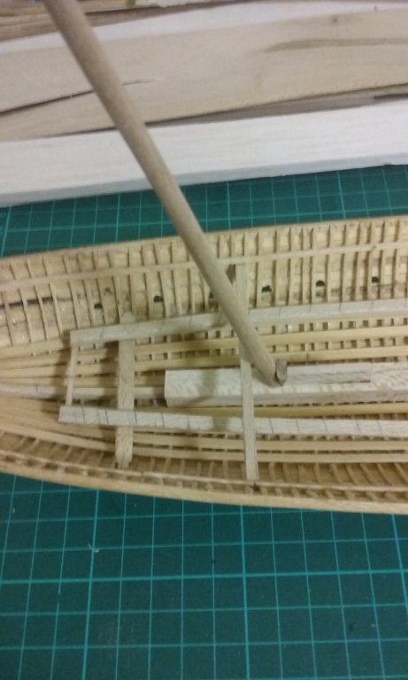
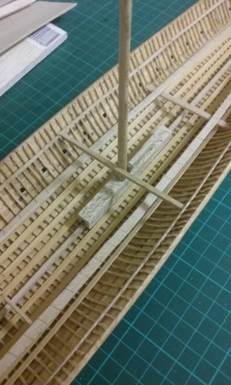
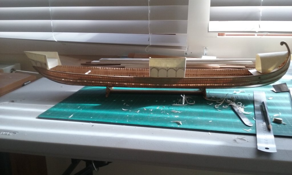
I've now added the mast partners for the fore and middle masts. These are the crossbeams to which the masts are lashed, above the mast step but immediately below deck level, to keep the mast in position. Sorry for the fuzzy photos - taken with my phone at night time - not terribly good lighting. Unfortunately I'd already put the beam shelf in and as the mast partners are fixed to the wales on each side they were a bit too long to fit past the beam shelf. With great trepidation I pulled the sides of the ship apart so the partners could go in. No nasty cracking or snapping sounds, so it was successful. In fact I had to do it about three times with the midmast partner because it was too long even to fit between the wales, so it ended up a little bowed. So I had to cut it shorter and go through the whole nerve-wracking procedure again. It worked, though. So that's all for the masts for the time being. I'm putting them to one side and concentrating on other things. Almost time to do the deck beams. But first I want to tie down the details - and particular the fixing - of the spur. Steven


-
Pat, The local library has "Age of the Galley" and I photocopied the section "From Dromon to Galea" about three years ago - in fact it was what inspired me to begin this build! Looking back at this quote I see that the original Greek passage says "Moreover, hides should be fastened to them [the dromons] against the ram [spur] of the enemy, so that the iron glances off in reaction and does not take hold . . ." I'd argue against the whole spur being made out of iron. First, making something seven metres long entirely out of iron could be done, but would be very difficult with the technology of the time, and anyway it isn't necessary - an oak spur, sheathed with iron would be considerably stronger. Wrought iron, made by hand, would be full of faults and inclusions of slag - the difficulty of making a sword at the time testifies to this. And wrought iron is pretty "bendy" - and far heavier than timber. I wouldn't use it as a spur. It's my belief that the "iron" in the above quote is an iron-sheathed point. A spur would have no need for any more iron than this if you weren't trying to protect the spur from the flames of the siphon. And as only the Byzantines had Greek Fire, enemy ships didn't need to protect their spurs against it. But as the Byzantines did have it, one would expect them to have metal sheathing and perhaps it was iron. It wouldn't have to be strong, just cover the wood of the spur. No, I don't have the MM article but I'd be very grateful for it. I'll PM you. Many thanks. Steven
-
Mark, there are certainly no references to this in the contemporary records, and as far as I can see this was not part of the tactics used. The spur seems to have been used to smash your opponent's oars and preferably steering oar and allow your marines to attack from the relatively unprotected stern, and perhaps even capsize the opposing ship. As usual, most of this is speculation, as contemporary evidence is either lacking or untrustworthy. Steven
-
Thanks Steve, Patrick and Pat. Another reason for the idea of iron plating on the spur is that Prof Pryor mentions a reference in the early 13th century Itinerarium peregrinorum et gesta Ricardi Regis (Itinerary of the pilgrimage and deeds of King Richard) to a (probably Italian) galley with a "rostris ferratis" ["ironed" spur]. (Age of the Dromon, p. 203) However, in this case the iron plating could not have been to protect the spur from the effects of Greek Fire, as this weapon was a closely guarded Byzantine secret. Perhaps it simply means that the spur had an iron point. In the Byzantine case, any metal would have been sufficient to protect the spur, at least temporarily. It would probably come down to which was easiest to get and/or apply. Lead would also be possible, but might be inappropriate because of its weight. Bronze or copper were probably easiest to get hold of and to work, so bronze might well have been used. This is all speculation anyway; we don't know it was done, merely that it would seem to be needed. Steven
-
Pat, I'd appreciate it if you can find it. Carl, I agree. But the Ancient Greeks and Romans used rams, attached directly to the hull which was shaped to receive them. The spur was a separate piece - rather like a knight's lance. The reason I thought of iron is simply that it's less dense, so using iron rather than bronze would probably reduce the weight and thus the leverage of the spur. Steven
-
Just checked again in Age of the Dromon and discovered there's documentation for the 13th century Sicilian galleys having spurs that were 10 metres long and 250mm thick. Presumably Prof Pryor applied his usual 3/4 proportioning between the Sicilian galleys and dromons to come up with the spur length for the dromon. Looks like I'll have to go back to 7 metres - and maybe 200mm thick. But that would be at the base - maybe if I make the spur quite a bit narrower as it approaches the point it will reduce the "tail wagging the dog" effect. Steven
-
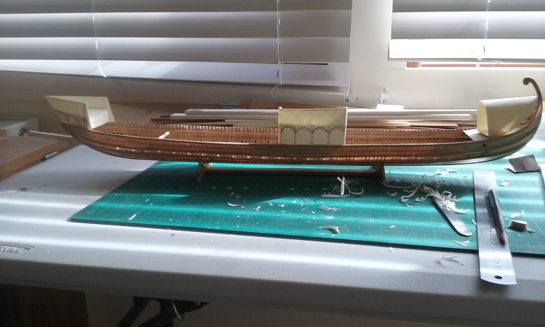
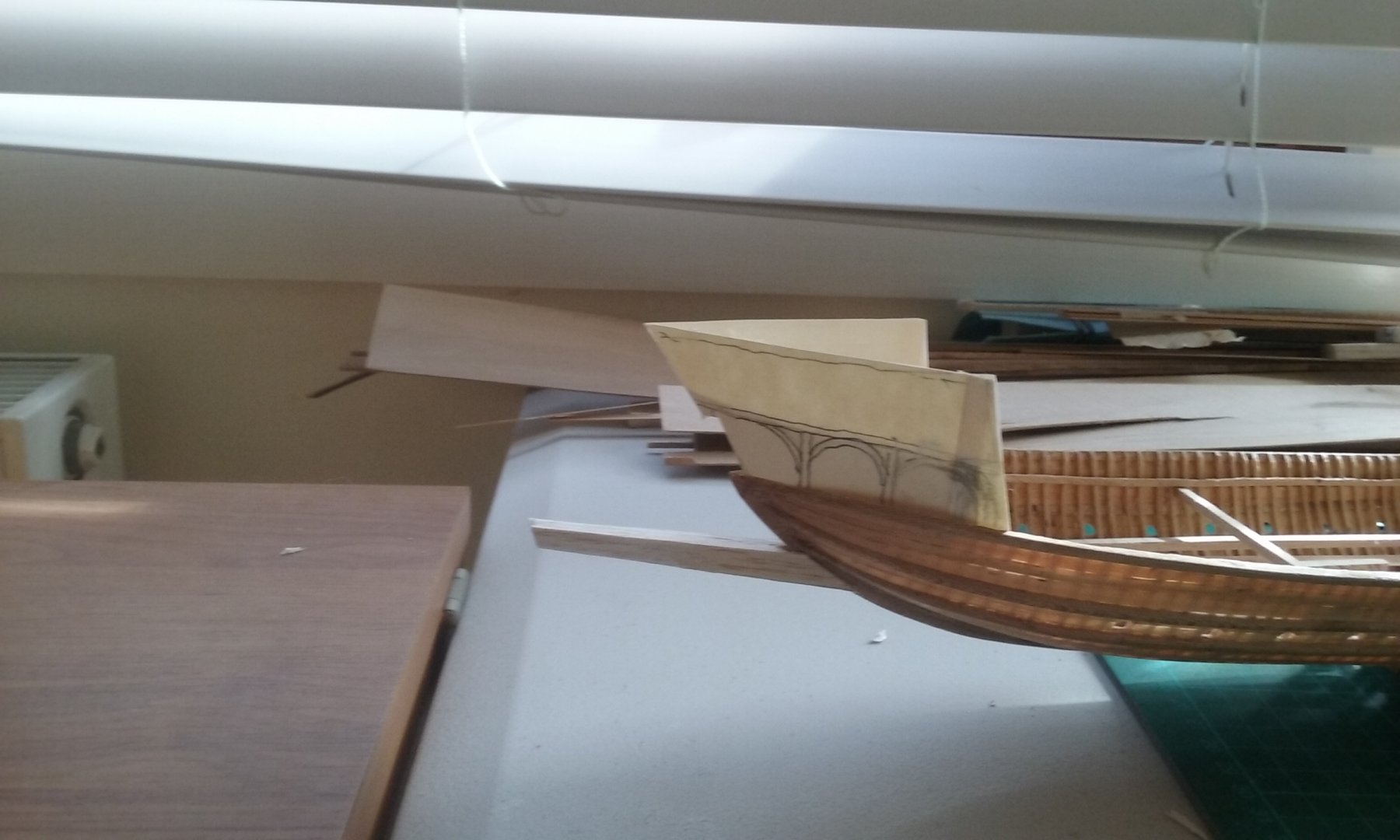
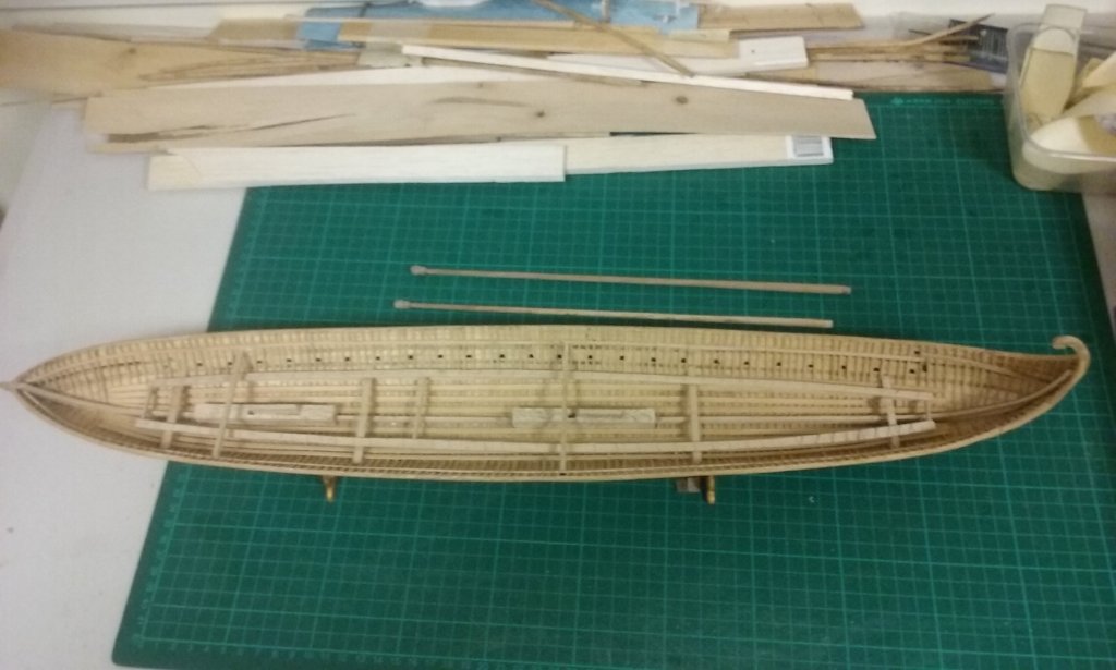
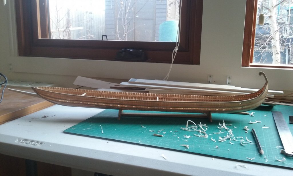
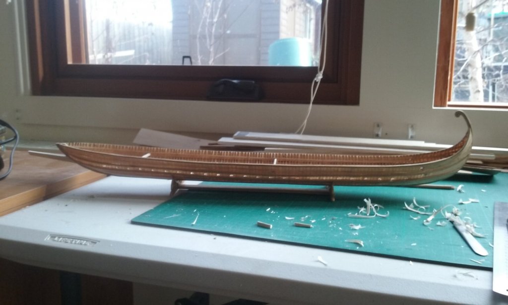
Thanks everybody for all the "likes". Having pretty much sorted out the masts, I'll be putting them to one side till they're needed. There's one more thing still to do, which is install the mast partners, the cross beams that support the masts just below deck level. I'll be posting on that shortly. The next thing to work on is the peronion or "spur", used in ramming enemy ships. Normally one would expect such a thing to be built strongly into the ship's structure as the forces involved in a ramming are pretty extreme, but Age of the Dromon shows that the Byzantine spur was definitely a separate piece, which was then fixed to the ship with a coupling (katakorax). How exactly this is to be done is currently a bit of a problem, as these things would have been pretty heavy and it would be necessary to transmit the forces in a straight line of thrust, rather than at an angle, so as to avoid damage to the ship. Also, sailing in any kind of a sea with one of these things bouncing around, coupled to, but not built into the ship would have imposed all kinds of nasty forces on the bow structure. I have some idea of how to do this, but it's all speculation - we have no idea how it was really achieved, and unless a dromon with peronion attached is found among the Black Sea wrecks, the chances are we'll never know for sure. One thing is that a couple of contemporary pictures, several centuries apart, show a support - perhaps a chain - running diagonally down from the prow supporting the spur near the business end. This would stop the spur from falling too far downward but wouldn't stop it being flung upwards or sideways by the motion of the vessel. Perhaps there were also side chains (or ropes) running back to the cheeks of the bow? If taut enough this could keep the spur pretty much static, much as a martingale boom does for the bowsprit in later ships. The diagram in Age of the Dromon shows the spur as 7 metres (21 feet) long. I made a balsa mock-up and if it's to be strong enough to withstand the shock of collision it seemed much too hefty for a ship this size - and the spur was almost certainly made of oak or some other heavy timber, and possibly metal-sheathed as well (see below). I cut it back to 6 metres 5 metres (oops! lost the photo!) and 4 metres The last two seem to be about the size one would expect, and something like the size shown in contemporary pictures (though these need to be taken with a pinch of salt). This would work better and impose less strenuous forces on the ship's bow. But I'd left out of my calculations the pseudopation (fortified wooden forecastle), which (in my version at least) leans forward at the bow. I think this takes the 4 metre spur out of the running - it wouldn't be far enough forward of the front of the forecastle to engage an enemy ship without a risk of damaging one's own vessel. So maybe 5 or 6 metres, but no more. The other issue is that the spur would be immediately forward and below the siphon - the Greek Fire projector. As it seems to have been pretty much the same as a flame thrower, the chances of flaming liquid landing on the spur would have to be taken into account, so I believe it would have been sheathed in metal, probably iron. It would not have to be very thick sheathing, just enough to keep the spur from catching fire from spills of Greek Fire. So I've got some fun ahead working out exactly how to attach this thing, how long it will be etc etc. Steven


-
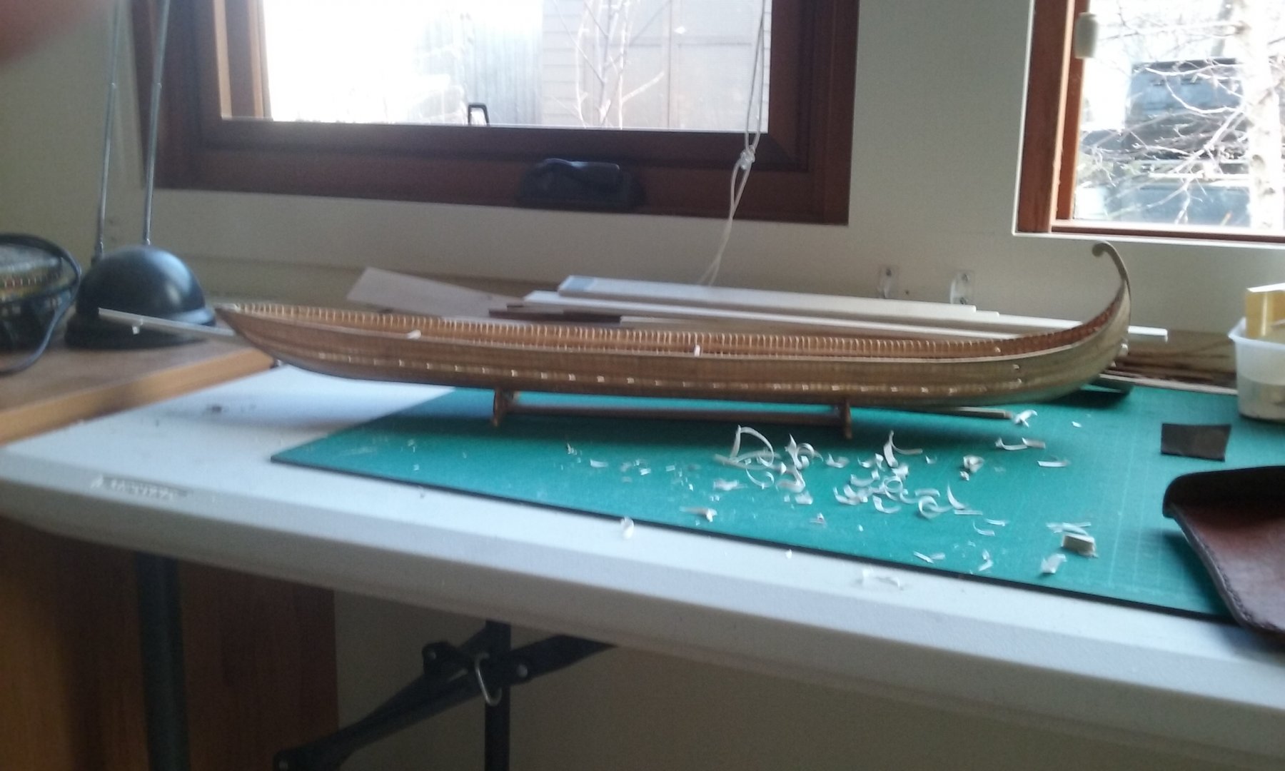
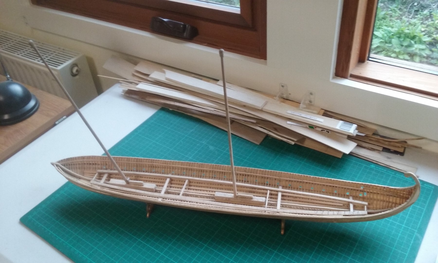
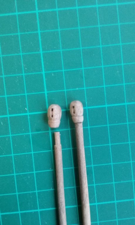
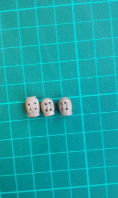
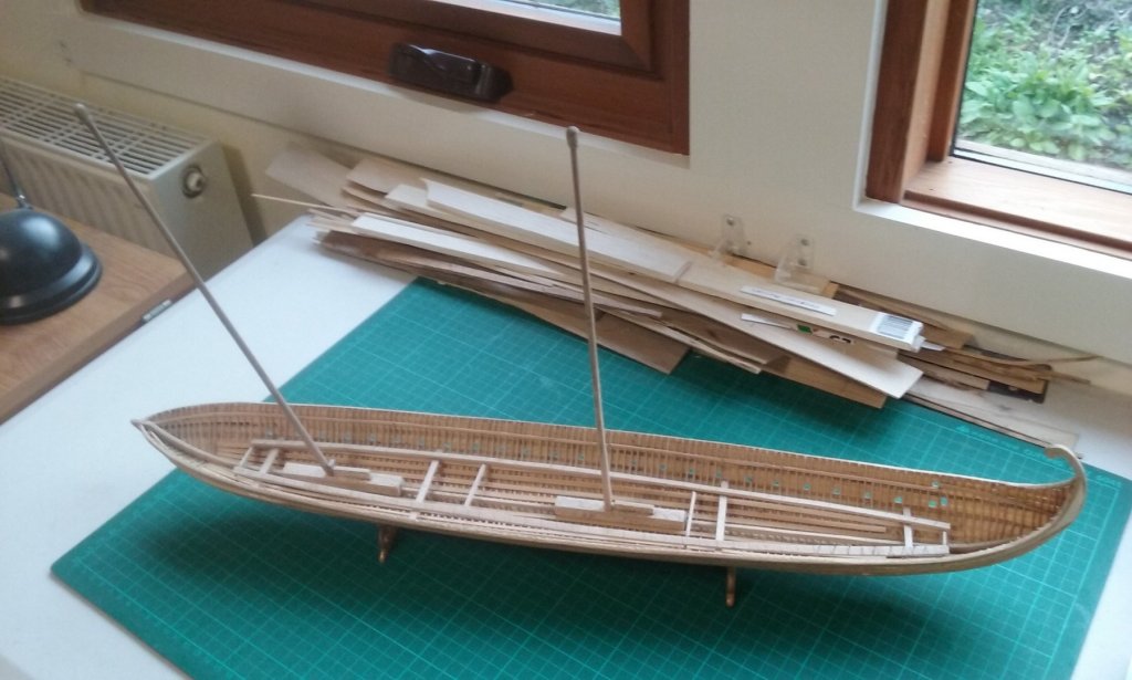
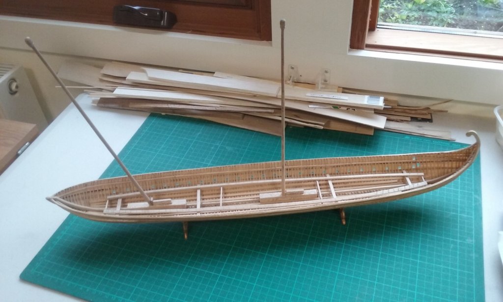
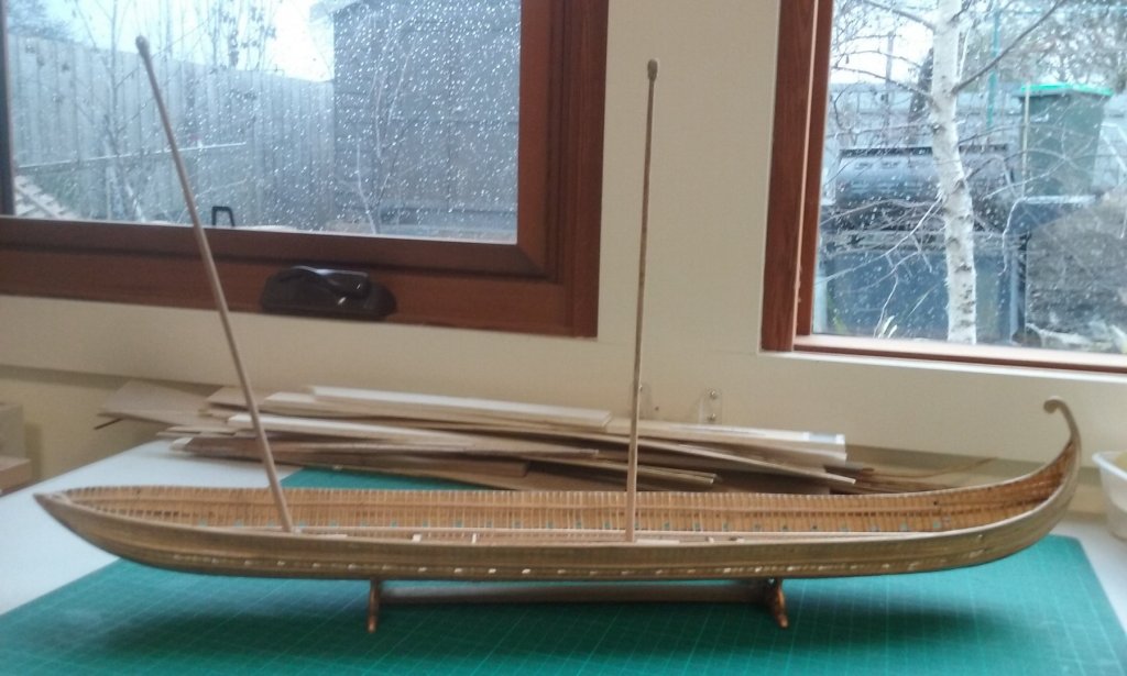
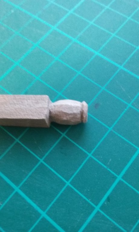
Here are the new calcets (might as well use the name - better than "blob") with a single sheave each. One has already been glued to its mast, the other ready to do so. One advantage of carving them separate from the mast itself is the sheaves can be aligned exactly fore-and aft without having to worry about lining them up with the tenon for the mast-step. And here are the three two-sheave calcets I made while I was waffling making up my mind. One still under construction, to replace one I wasn't happy with, when I changed my mind. And look! Here's another milestone - both masts in place, dry fitted. Starting to look like a ship! From above at various angles . . . shows how the mast angles can fool the eye. The midmast is vertical; the foremast has a rake of 13 degrees. And here she is from the side - with a lovely Ballarat winter's day outside. Steven
-
Dick, this objection would presumably also apply to Prof Pryor's 1984 lateener, but on reflection, if the halyard is belayed to the gunwale I think the yard should slip in between the mast and the halyard so it shouldn't be a problem. On the other hand after a lot of soul searching (and an equal amount of waffle) I've decided to go back to my first thought and have a single fore and aft sheave in the calcet (a name which I discover comes from the word khalkision used in the Byzantine texts on dromons to describe a mast with sheave incorporated in the top). And a pair of single or double-sheaved blocks for the halyard downhaul, leading aft from the mast. Am I right in thinking single-sheaved blocks would not convey any mechanical advantage? Steven
-
That's a very sensible and systematic way of putting frames together to shape the hull. The Venetians were very good at this kind of thing, and your jig looks very good. Steven
- 263 replies
-
- 2
-

-
- nave tonda
- round ship
- (and 2 more)
-
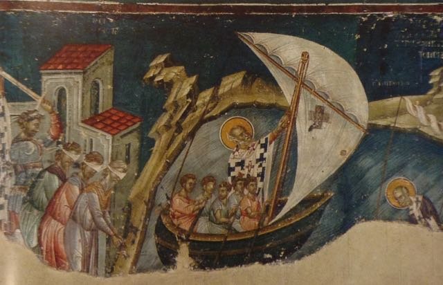
Dick, just checking - Prof Pryor shows the sheaves in the calcet across the ship, not fore and aft? The St Nicholas picture could be interpreted that way, and the Greek Fire could well represent two transverse sheaves. It would mean the halyard would be belayed to the side of the ship, not fore and aft? I think I might do that - it should cancel the problem of chafing. Pat, my reading suggests that not all the oarsmen rowed all the time - sometimes only the forward ones rowed. The Jason Voyage guys certainly did this, rowing in shifts to give each other a break. Again, all the upper oarsmen doubled as soldiers in battle (so the archers were drawn from their ranks), and so there should be plenty of manpower available. And the ship could be kept under way by the lower oarsmen if needed while the sail was raised or lowered. I like your idea of the double sheaved calcet and a single sheaved block. It does seem like a sensible way to go - no need to make raising and lowering the sail any more difficult than it has to be. And certainly, there have been a decent number of blocks discovered in the archaeological finds. Steven
-
Thanks, Mark. I'm not an experienced sailor - I was in the sea scouts when I was a kid. We sailed clinker-built 18 foot ex-navy gaff-rigged cutters. Lots of fun, but I've certainly never studied up on the theory, and my knowledge of mechanical advantage dates back to high school, and never applied to sailing. So maybe I just go with the single sheave at the top of the mast. I still haven't glued the "blobs" in place, so I'm not yet committed (though maybe I should be . . .) I'd thought the double sheave in the mast would be combined with a double-sheaved block between that and the yard, but I admit my ignorance on all this and it might be a really dumb idea. I was originally going to just go with the single sheave (as can be seen in the first foremast I made), then I saw something about double-sheaved assemblies at the top of the mast on mediaeval Mediterranean ships. But that might be completely inappropriate to something like a dromon. Particularly as you say, with oodles of available manpower who needs mechanical advantage anyway? Steven
-
Yes, and very few of the surviving northern representations (or any of the others, for that matter) show the break of the poop looking from the bow. I think there's a single one from Master WA that does (and shows it open), and that's about all. Perhaps the idea of removable "partition walls" would be best, particularly as it's a structural matter for your model. Steven
-
I'm still very much feeling my way with all this stuff. Would those of you "in the know" think I should go back to a single sheave at the top of the mast, and get the mechanical advantage from multi-sheave blocks and tackle on the halyard downhaul itself? Steven
-
Well, it had occurred to me that having that area open to the elements could get pretty bad at times. Rather like being in an open boat. One thing you might try is getting in touch with the people in Bristol England who operate the Matthew, a reconstruction of John Cabot's ship of 1497. She is at least partly open in this region - maybe they can tell you what it's like under the aftercastle in bad weather. By the way, the arched openings have removable shutters to close them in. Not a bad idea. Steven
-
Good point, Pat. The foremast should be ok - Prof Pryor has it about 70 degrees from horizontal (i.e. 20 degrees forward rake), but it's at 77 degrees (13 degrees) on my AutoCad drawing . The aftermast, however, is vertical, and there may be a problem with that. I can only suck it and see. Steven
-
I can't remember off the top of my head, Dick. I'll have to get back to you on that. Steven
-
Patrick, it seems to me that the wall of the aftercastle is artistic licence, based on a vessel later than 1500AD. However, the decision is yours. It's your model and you can do what you like with it. Steven
-
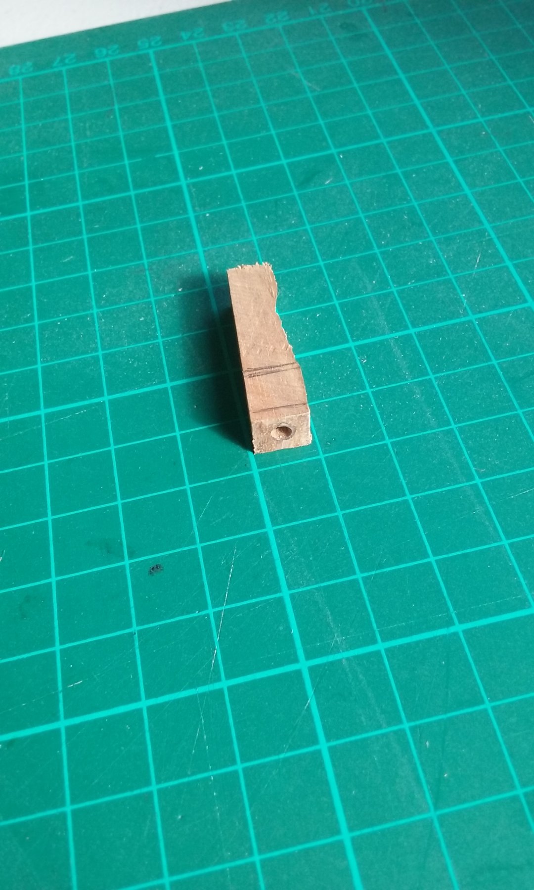
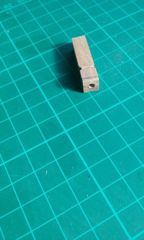
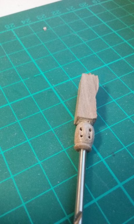
The "blob" at the top of the mast that holds the sheaves for the halyard is a bit too small to match the one in the picture I based it on. So I'm making two new ones, one for each mast. Also they'll have two sheaves instead of the single one in the original one I made, as the forces involved in hauling up the yard are pretty large. The drill bit in the hole is to ensure the tenon for the blob is at the correct angle, as I don't have the luxury of a drill press to drill the hole exactly in line with the axis of the blob. Had I thought of it earlier, I could have used the drill bit as a guide in carving the blob itself and not have to adjust the tenon on the mast. I expect I'll have to re-drill the holes for the sheaves through the tenon once the blob is in place, so the halyard can pass through the sheaves. Steven


-
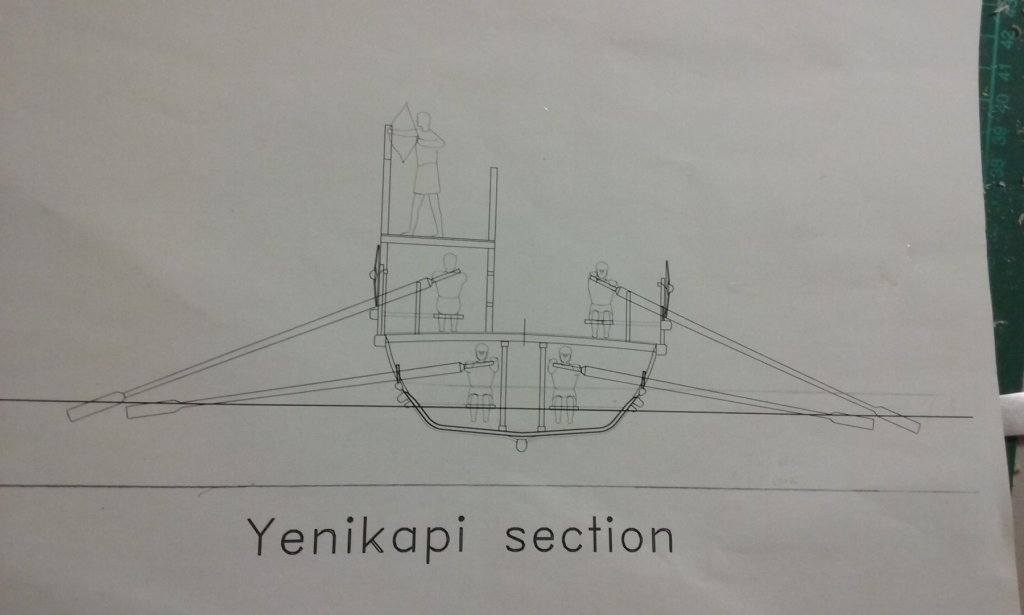
Here's my theoretical midship section, to give some idea of the oars. Sorry, I wasn't holding the camera quite straight so it looks like the ship has developed a list. It was very difficult getting enough headroom for the lower oarsmen while keeping the ship low enough in the water to allow a workable angle for the upper bank of oars - the deck beams are only the equivalent of 100mm (4") deep, which won't span from side to side of the ship without bowing, so there are a pair of beams running the length of the ship to support them, held up in their turn by a series of posts - positioned so a person can walk between them but allowing the oarsmen enough room to row. None of this lower stuff appears on the model, but I had to work it out to my own satisfaction to see if it would work in the real world. Probably not the way they actually did it, but it is workable. Steven
-
Oh no, these oars are only correct from the oarport outwards, Druxey. I've built a framework of my own invention to support the lower oars rather than have to make 50 lower deck oarsmen (who will be invisible anyway), and reduced and bodged the inboard section of the oars to go on the framework. See my post of 6 July above. Sorry if I gave the wrong impression! Prof Pryor's reconstruction has the outboard length as 3.395 metres (including the blades) and the inboard as 1.265 metres (including the handles). Though I'm not following his reconstruction completely as I believe the Yenikapi finds have invalidated some of his conclusions, I have followed it in regard to oar lengths (well, the bits you can see, anyway). Steven