Louie da fly
-
Posts
7,990 -
Joined
-
Last visited
Content Type
Profiles
Forums
Gallery
Events
Everything posted by Louie da fly
-

Mediaeval Shipwreck found in England
Louie da fly replied to Louie da fly's topic in Nautical/Naval History
Couldn't agree more! Steven -
You might be interested in the build log of a Maori "Waka" (dug-out war canoe) at https://modelshipworld.com/topic/16639-waka-maori-war-canoe-by-john-allen-124-finished/#comment-516441 It references a very informative book on them which contains a discussion of techniques used by the Maoris to build these surprisingly sophisticated vessels. Steven
-
https://petapixel.com/2022/07/21/sunken-medieval-boat-is-englands-oldest-ever-shipwreck/?fbclid=IwAR2pFJTcpnptoFjyONnmp1jyHw987M5JVROV3hjW2vFHxDROGXXy6KSsCRQ Looking forward to finding out more about this one. It's been dated to 1242-1265 - a little before my Winchelsea nef. I'll be interested to see how much of the hull they have recovered, and what it tells us about British ships of this period. Steven
- 4 replies
-
- 11
-

-
G'day, Farmer. What part of Oz are you living in? Depending on the State there are various resources available. I can't help with the kits - I do scratch builds, so I don't know what kits are best/worst. But so long as you keep at it, you should be able to get through them (keeping in mind that everybody makes mistakes, so don't get discouraged by them, and wood is a very forgiving medium - you can often fix the mistakes). And welcome to the wonderful world of ship modelling. Steven
-
Wonderful work, George! I'm looking forward to seeing more. By the way, where in Istanbul is the Naval Museum? I've been to the military Museum and the Archaeological Museum, but I didn't know there was a naval one as well. Steven
-
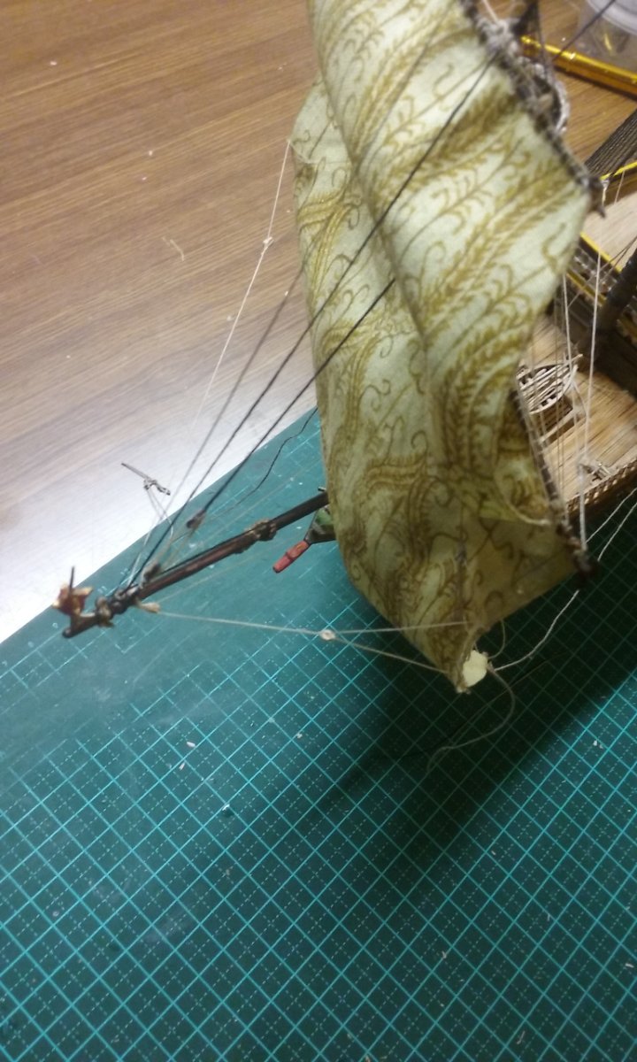
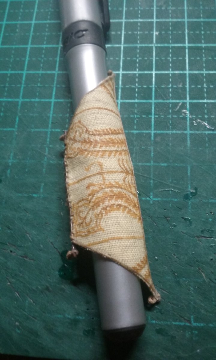
And some more rigging for the fore course and topsail. Bowlines and their belaying points - cleats on the central bulkhead of the forecastle A clearer view of the forecourse braces and their belaying points. Curving the fore topgallant - the boltropes are simply glued on with PVA (white) glue and wetting the edges of the sail enables it to be curved around the barrel of a pen. The six blocks for the fore topsail braces are now complete. Steven


- 740 replies
-
- 11
-
-
- Tudor
- restoration
- (and 4 more)
-
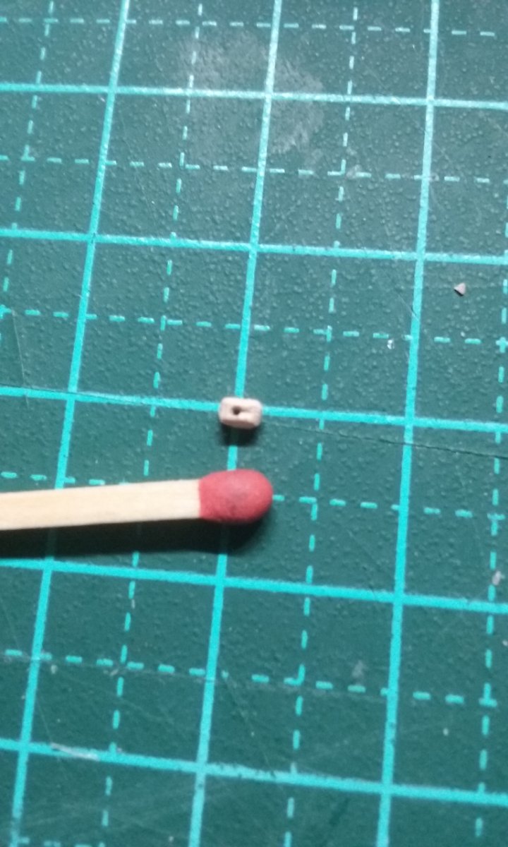
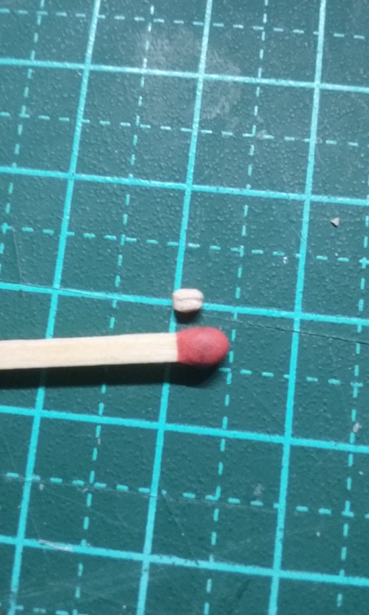
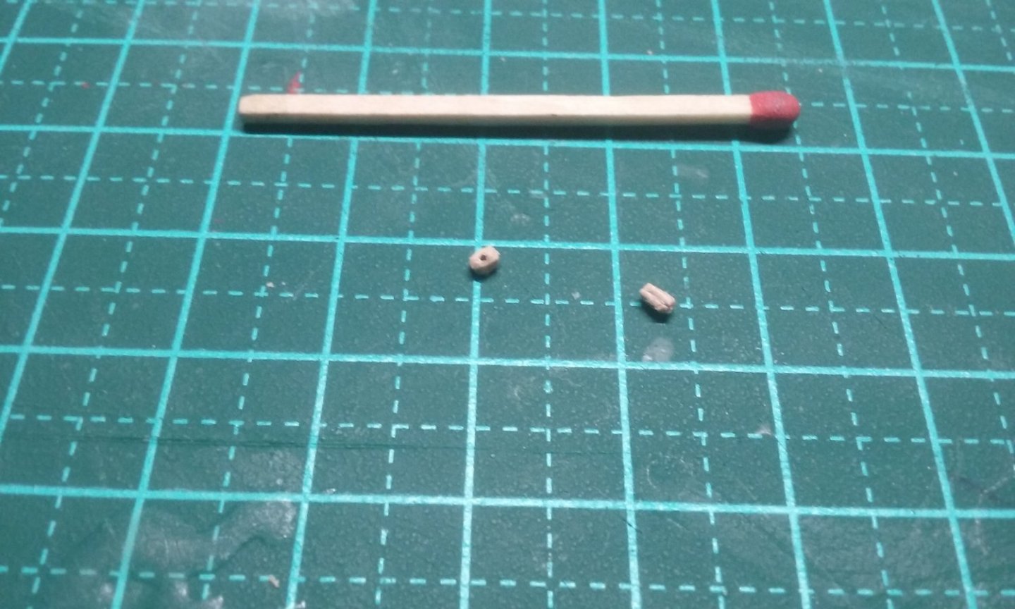
These ones are (approx) 2mm x 1.5mm. Just within my capabilities . . . Steven
- 740 replies
-
- 4
-
-
- Tudor
- restoration
- (and 4 more)
-
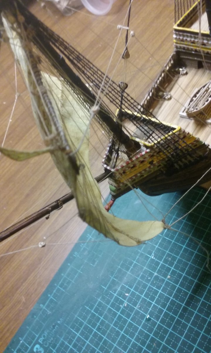
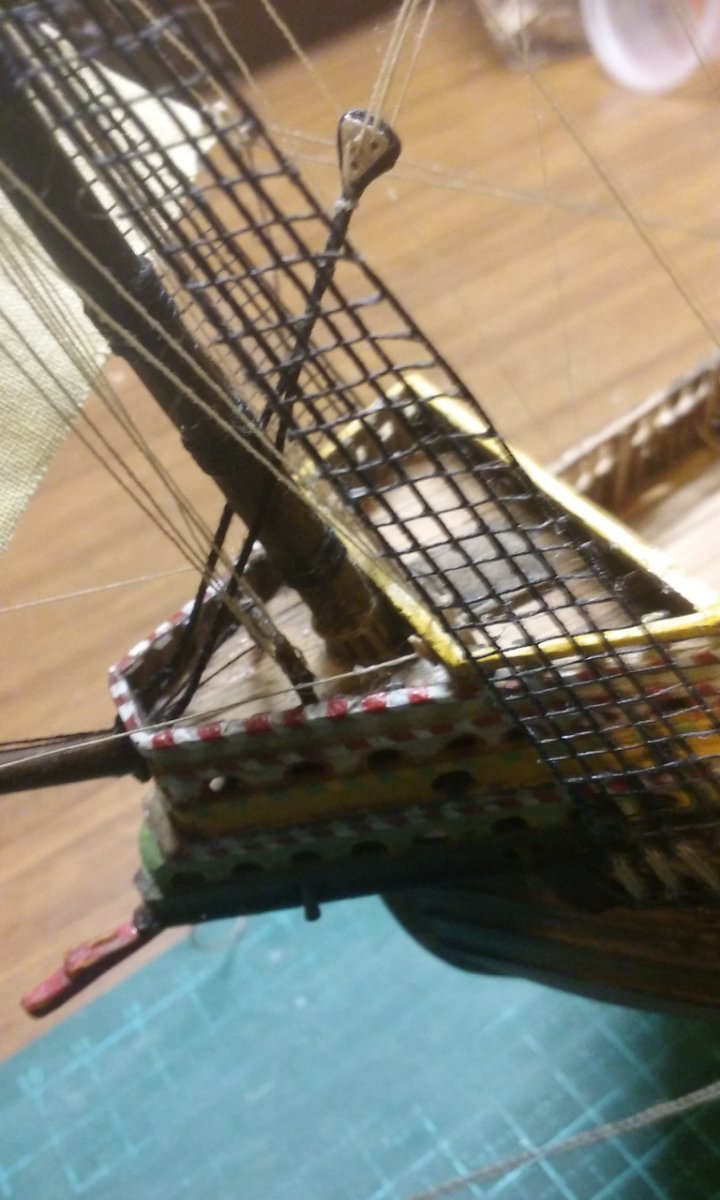
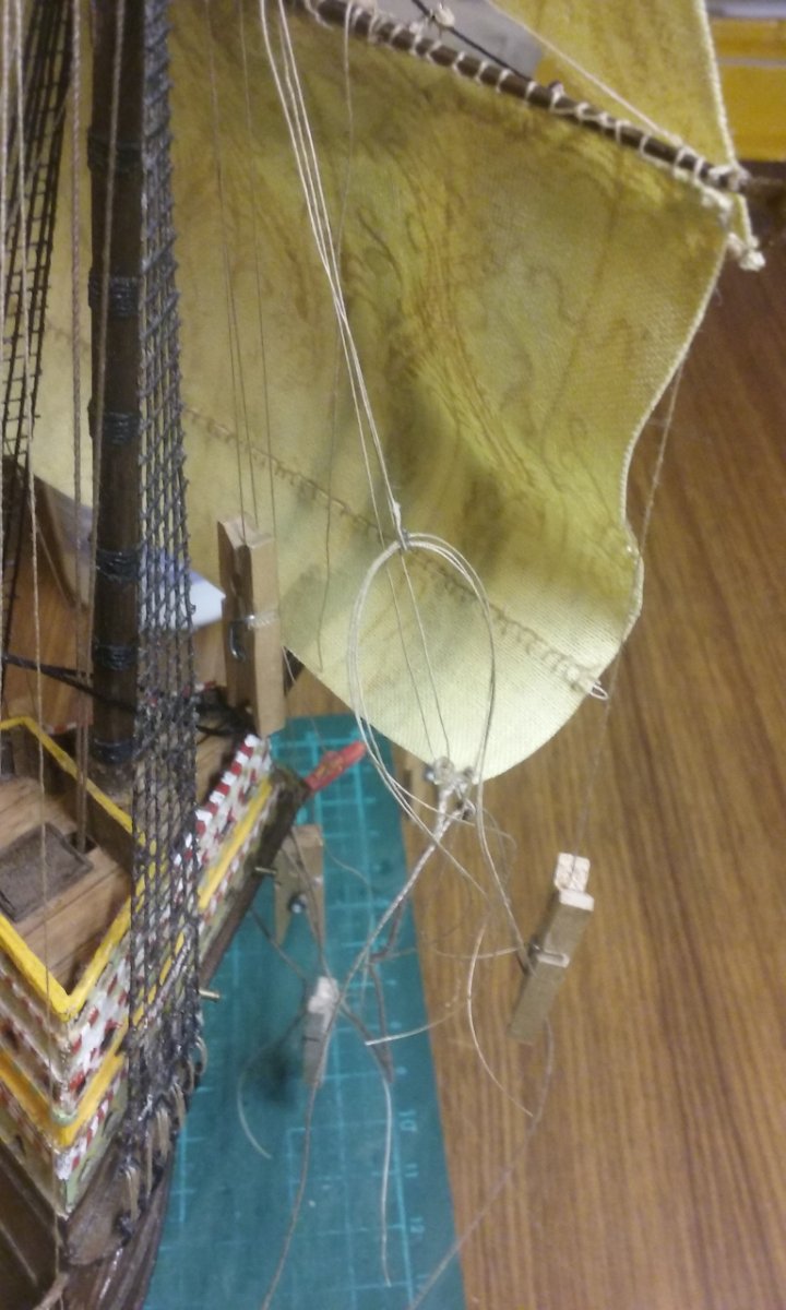
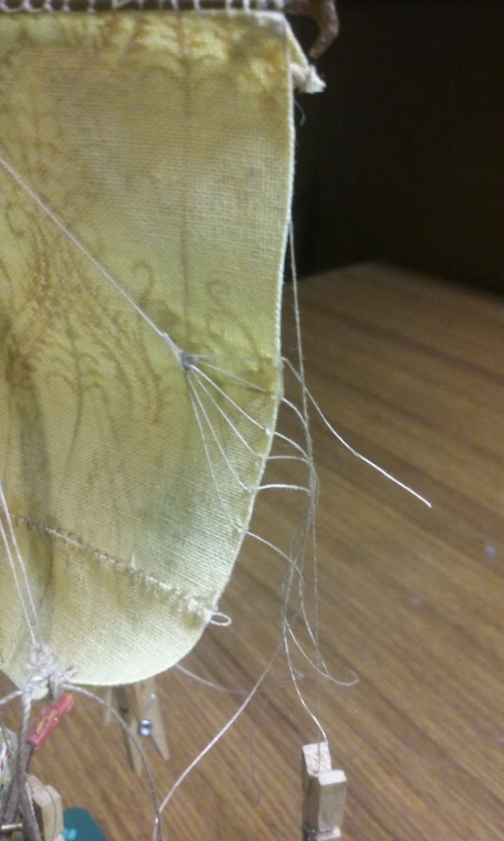
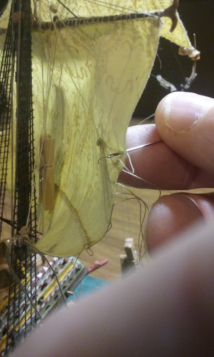
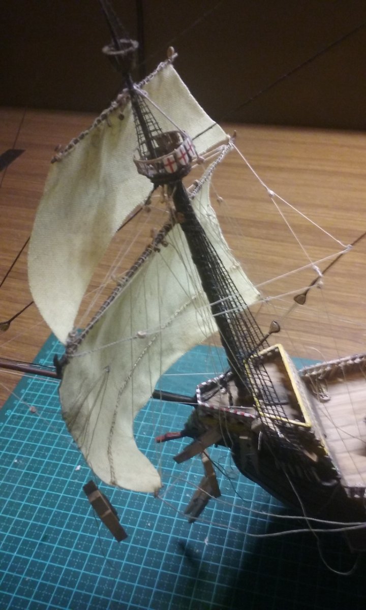
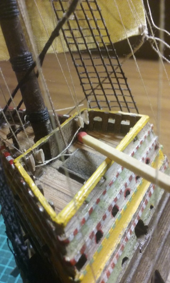
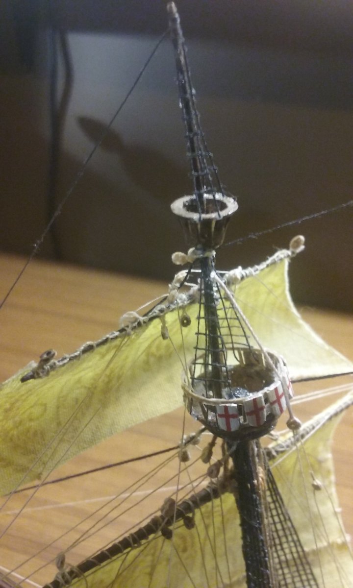
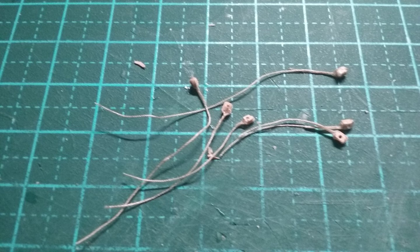
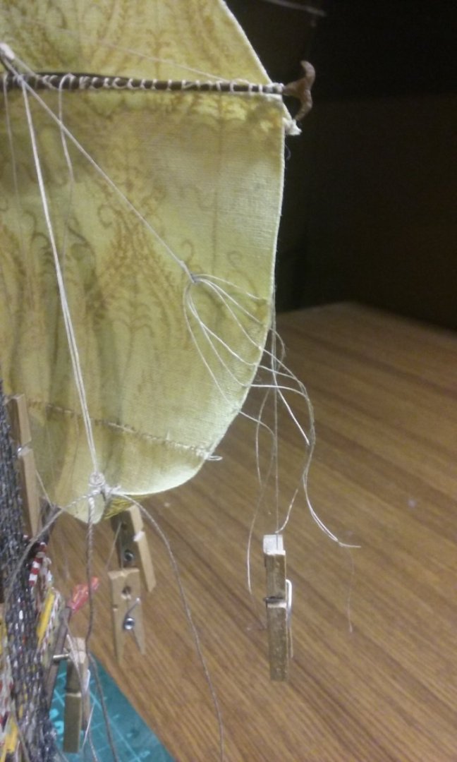
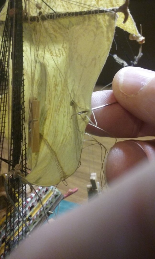
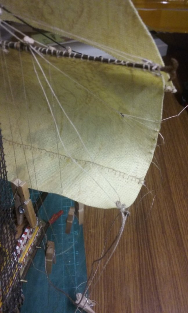
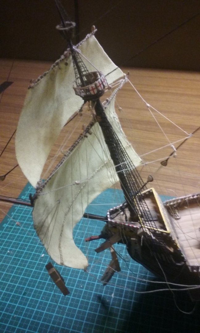
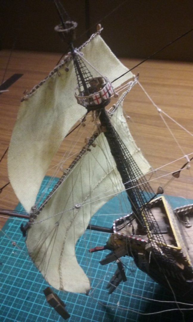
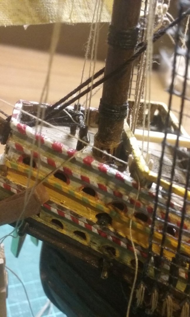
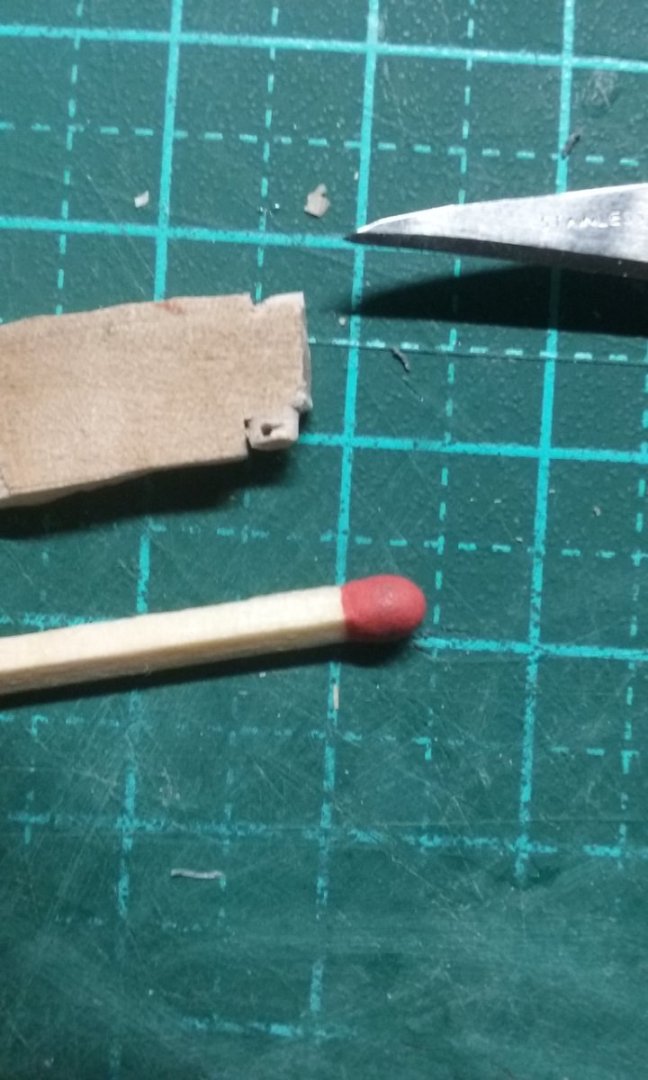
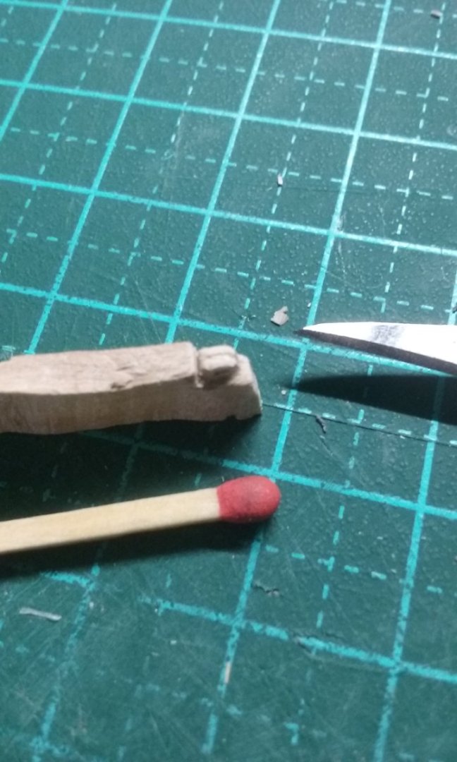
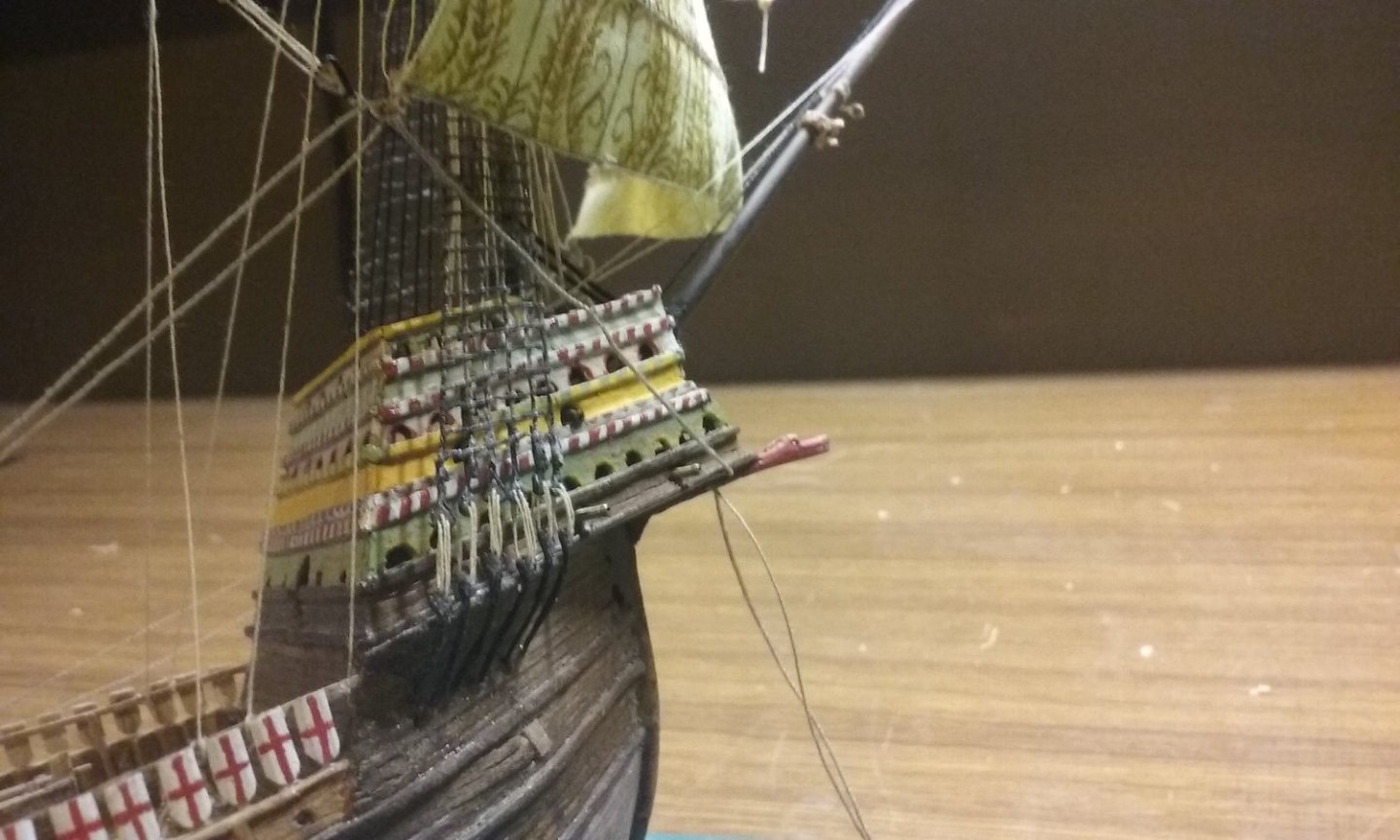
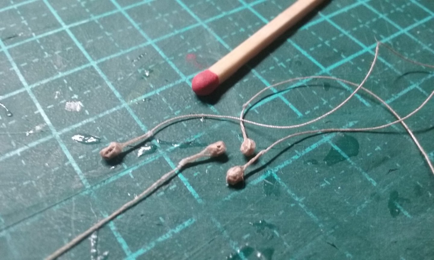
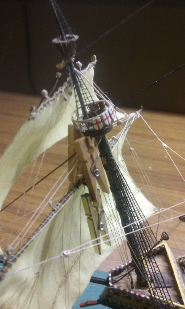
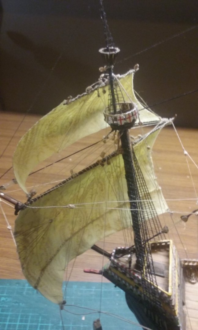
I haven't posted for a while - not because I haven't been doing anything, but because the progress wouldn't have been terribly obvious in a photograph. Finally there's been enough progress to post photos for the forecourse and fore topsail rigging. These are in the sequence I worked on the various bits of rigging - having now completed, there are several things I would have done in a different order (access with tweezers, taut ropes going slack as the next one went on, things like that). First the martnets - these were superseded by leechlines about the middle of the 17th century, but this appears to be how the leeches of the sails were furled in 1545. The martnets go both sides of the sail. There's a deadeye for each set of six - a line goes through each of the three holes in the deadeye and each and each end of the line is fixed to a cringle at the leech of the sail. First the deadeye with the three lines going through it, then threaded loosely through the leech (too small for cringles!). The little clothes pegs are acting as weights for other ropes that are in place but not finalised. Fake cringles - just went through the fabric with a needle and looped the thread around the edge and back through the hole. This is one of the things I will change - adding other ropes interfered with the tension of the martnets. When I do the mainsail I'll leave them unfinished till a lot of other stuff is done, and only fix the ends right at the last minute. Rear martnets in place. Adding braces. They go from the mainstay to blocks on pendants from the yardarms, and thence back to a pair of blocks attached to the stay and down to deck level. I've belayed them to the side rails. Cleats to belay the foresail lifts and (I think) topsail sheets - it's awhile ago, and there are so many ropes. Note the size of the cleats compared to my enormous match stick. And the second photo shows more ropes (sorry, can't remember which ones!) belayed to the bitts. Making blocks out of pearwood. They are gradually getting more and more like real blocks (even down to the groove for the strop) , but they're pretty tiny, so detail suffers. As it turned out, they were still too big, so unfortunately I had to cut them down further and lost even more detail. They also keep splitting and having to be glued back together before they can be put to use. And in almost all cases I have to re-drill the holes - they seem to close up as I put the strops on and the thread won't go through. If I remember, I re-drill them before I put them into place - it's very annoying and difficult to drill them out with my big heavy power drill once they're in position on the ship. (Yes I know, there are better drills to use, but I've not got that sorted). So here's a bunch of them ready to go. Foresail lifts and topsail clewlines, and blocks for various other things - the ones at the middle of the yard are for the buntlines (fortunately the topsails don't have martnets). Fore topsail lifts and clewlines belayed to the top. Next to do the topsail braces - the same as the braces for the course, but they have an extra pair of blocks - one pair at the topmast stay, another pair at the foremast stay and one for each pendant - so I have to make six of the rotten things for one pair of ropes! Here they are at various stages of completion. VERY slow progress - mostly because of having to make so many blocks. They're just within my skill level, and so I feel honour bound to make them myself. And anyway I don't think you can buy them that small. Steven


- 740 replies
-
- 12
-
-

-
- Tudor
- restoration
- (and 4 more)
-
Krisan, I agree there's no need for you to get a kit. You can work with what you have. I started making ship models when I was in grade school - there were some pretty good plastic models available cheap in those days (affordable out of my pocket money), but I made two wooden models before I was old enough for high school, cut out of solid hunks of wood - both square rigged sailing ships, one with two masts, one with three. I was a sailing ship fanatic, and I had several picture books which I used as a basis. The sails were made out of art paper and the rigging was sewing cotton. I was lucky - my Dad was very supportive and he had a pretty well supplied workshop, but I mostly did it with simple hand tools - you really don't need very much to produce a good result. Looking back on them, they were a bit rough and ready, but I was very proud of them - and even today, at the age of 72, I'm still proud of what I achieved back then. So go for it. The members here will be very helpful - ask as many questions as you like - and (most important) enjoy yourself. Best wishes, Steven
-
Nice work, mate. A little birdie tells me your next one is to be the Niña or the Piñata. (Yes, I know I've posted this somewhere else . . .) Steven

- 74 replies
-
- 3
-

-

-
- Santa Maria
- Amati
- (and 1 more)
-
I'm going to have to make one of these! Steven
-
Hi Shane, What can I say but WOW - just WOW! Your model looks to have been made around the turn of the 20th century. It's of a kind of ship usually known as a pre-Dreadnought. It's not an accurate model, but it's a real collector's item. It does look a little like the Prince George; it's certainly nothing like the King George V. It obviously needs (gentle!) cleaning, and repair. If you put the word "restoration" or "restoring" in the search bar (top right of this page) you'll find some old neglected models which have been cleaned up and restored to their former glory. I believe this one deserves the same treatment. If you're considering restoring this beautiful and historic model, a log posted in Build Logs for Scratch Projects with the tag "restoration" added would be appropriate. There'll be a lot of people on MSW fascinated by this model. It's a real find! Steven
-
Hello from the outskirts of Sydney
Louie da fly replied to rumbeard's topic in New member Introductions
Welcome to MSW, Rumbeard, from sunny Ballarat! There's quite a few Aussies on this forum, and I'm sure you'll get to know them as time goes on. You might like to check out RGL's builds, too. Amazing models - different medium (plastic), but probably right up your alley. Steven -
I can't rely on the accuracy of this image, but it is contemporary - perhaps the 1590's - supposedly the capture of the Cacafuego by the Golden Hind. It's the only one I've been able to find. Hope it helps. Steven

-
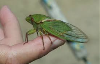
More like a Greengrocer (big cicada) I just measured it; just on 40mm. Looking back at the original pic on the Anthony Roll I could have made it quite a bit bigger, maybe as much as 15mm more (and there's room for it on the weather deck). Steven
- 740 replies
-
- 4
-
-
- Tudor
- restoration
- (and 4 more)
-
Looking good, mate. I agree, walnut's not a good carving wood. The best is apparently boxwood, but I've never tried it - I have stacks of pearwood and apricot wood, which will probably last for the rest of my lifetime. Steven
-
Yes, I found that out by accident as well. Great for holding things that would otherwise not stick. Beautiful work on the spinet, by the way. My brother once began scratch building a harpsichord (he was about 19, as I recall). Unfortunately his ambition was greater than his abilities and he never finished it. A pity, really. Steven
- 63 replies
-
- 5
-
-
- Finished
- Khufus Solar Boat
- (and 1 more)
-
Landlubber from a landlocked country
Louie da fly replied to UMH's topic in New member Introductions
Ah, understood. I thought it was a language problem. Steven -
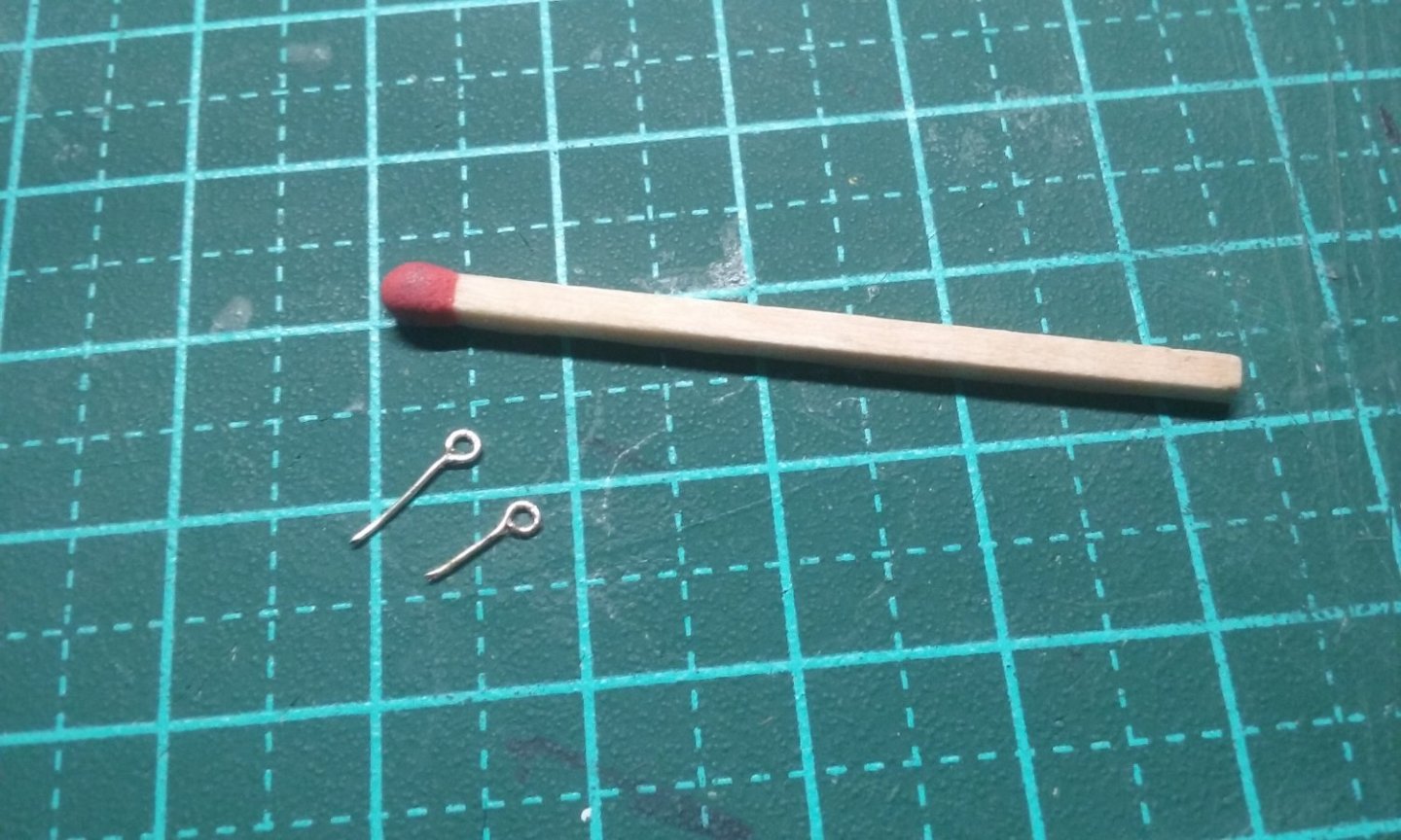
Thanks everybody for the likes and comments. OC, strictly it should probably be better described not as a replica (since so much is unknown) as a speculative/theoretical reconstruction. I've just been playing with carving out blocks. When I first started I just made them circular with a hole in the middle, but as I've gone along I've been thinking - what the hey, it doesn't take much more work to make them look like real blocks, so gradually I've been making them closer and closer to the real thing. No sheaves at this scale, obviously, and just a single hole for the thread to go through (two would split the block), but I've started making them longer and shaping them more like a real block, adding a groove for the strop and putting the hole closer to the end of the block, like it's got a sheave, (though I'm not always as successful as I'd like with that - the one below has it pretty much in the centre). Note the enormous match stick which I keep to fool you guys into thinking this stuff is really small. And I've been making eyebolts (or perhaps fake ringbolts) out of thin wire, wrapped around a needle. So far I've got just about all the running rigging attached to the larboard side of the forecourse - buntlines, martnets (forerunners of leechlines), clewlines, halyards, lifts, sheets, tacks, bowlines and braces, and I've started on the starboard side. No footropes - they hadn't been invented yet. On reflection it would have been easier to do each line on both sides at the same time, but I'm learning as I go and each line required enough getting my head around it without also doing it twice. It did make the whole thing a bit lopsided, especially as I've been keeping the downhauls taut with tiny clothes-pegs, which have been weighing that side of the sail down. Now that I'm more confident, when I get to the next sails I'll be doing both sides simultaneously. And next time I won't add the topsail until I'd done all the rigging on the course. It made access very difficult. Well, we live and learn. Still bumbling along - taking long breaks between steps so I can recover my equanimity and face the next step with a fresh mind. But making steady progress and pleased with how it's going. Steven


- 740 replies
-
- 14
-
-
-
- Tudor
- restoration
- (and 4 more)
-
Landlubber from a landlocked country
Louie da fly replied to UMH's topic in New member Introductions
Welcome, Daniel. When Dave E said don't be shy, he meant don't be too cautious or timid (scheu? timido?) if you want to ask questions. Everyone is very helpful and we only learn by asking questions. Steven