Supplies of the Ship Modeler's Handbook are running out. Get your copy NOW before they are gone! Click on photo to order.
×

Jason
-
Posts
202 -
Joined
-
Last visited
Content Type
Profiles
Forums
Gallery
Events
Everything posted by Jason
-
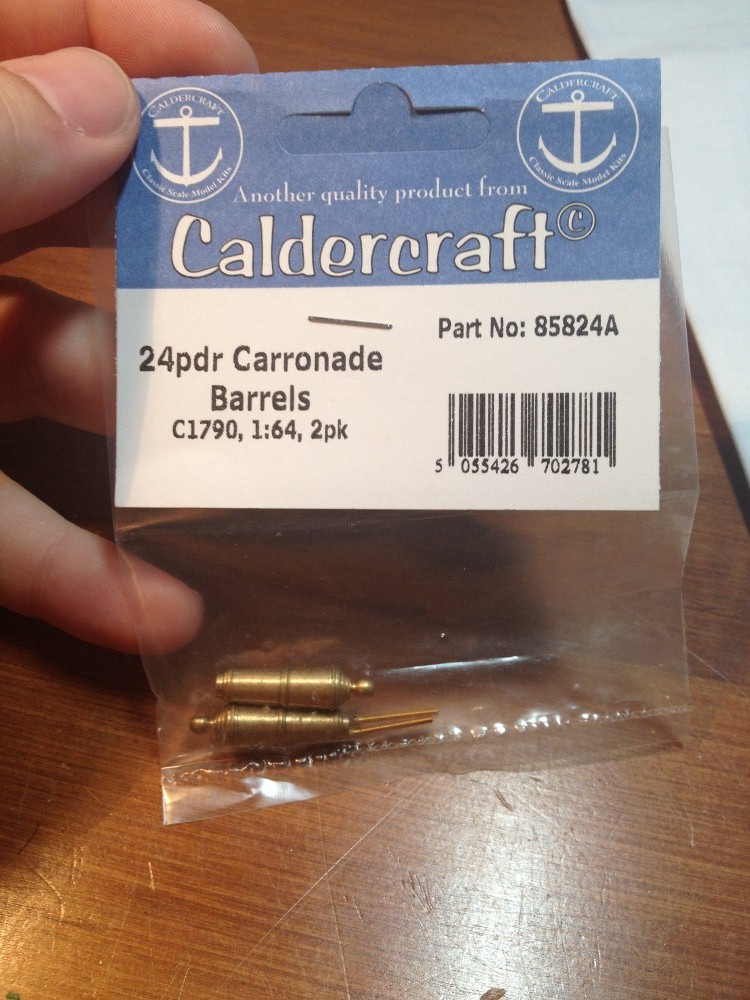
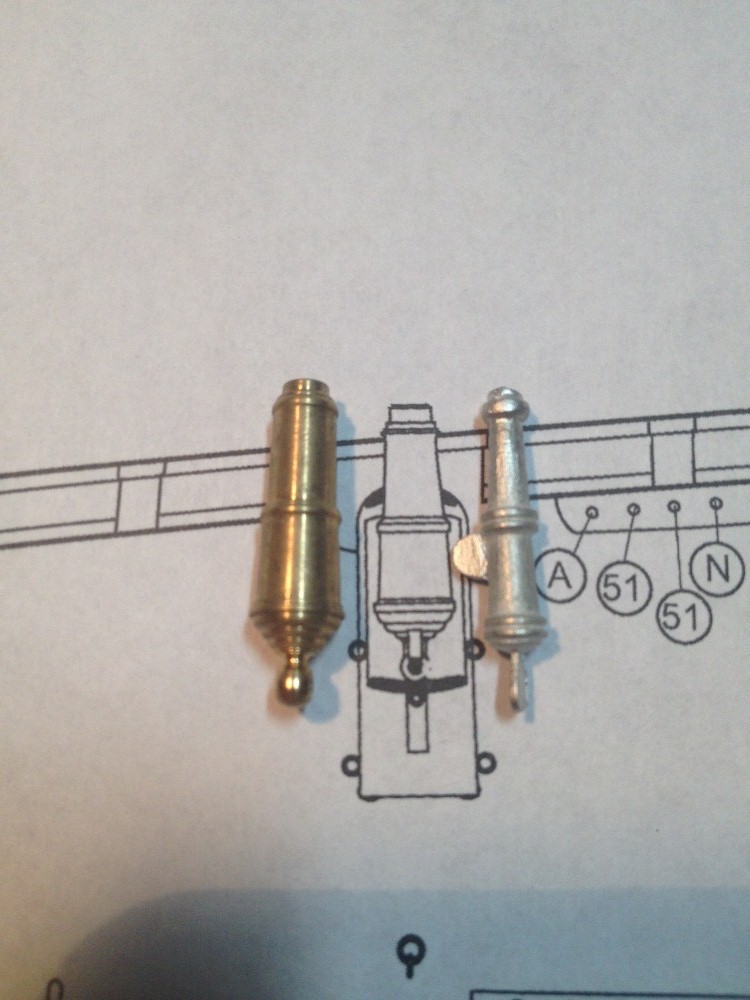
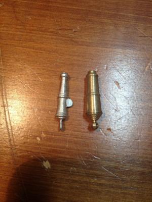
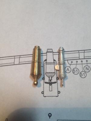
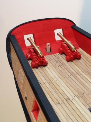
 An Interesting Point of Comparison: I have been pondering what to do about the main armament for my Syren for some time. I knew from the moment I first rummaged the box contents that I did no want to use the kit supplied carronades. To me, they look proportionally similar to a swivel gun. It took a long time to figure out what I wanted to use, because for one thing there are not really that many commercially available carronades out there. I toyed with the idea of making them, or at least one and then casting the rest, but I had it in my head, that I was going to use brass pieces. So enter Caldercraft's 1:64 24lb carronades. I could not find them in the US, so I ordered them from Cornwall Model Boats. I only bought a couple to be sure that I wanted to use them. So, lets compare them to what was supplied, To me there is no comparison here. The brass piece has much more accurate proportions than the white metal piece. So, how do they compare to the plans? as you can see they are actually both a little long. However, you can also see that the brass piece has the appropriate width and proportions. The Verdict: Overall I am happy with the size and shape of the Caldercraft pieces, and I will order the remaining number from Cornwall Model Boats. As an aside, I received my order from the UK to New Jersey in about a week. I am interested to see what sort of issues will pop up down the road, but I am fairly certain that the overall look will be satisfying. I hope this helps anybody that my be thinking about going a similar road with their Syren.
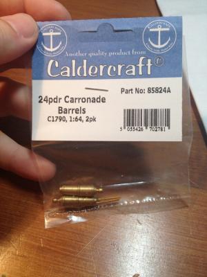
-
Amazing work Johann! The scale figure next to the carronade is a great image, and gives a really good idea of the relative size of the battle station in a way not often seen in models!
-
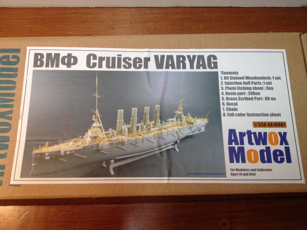
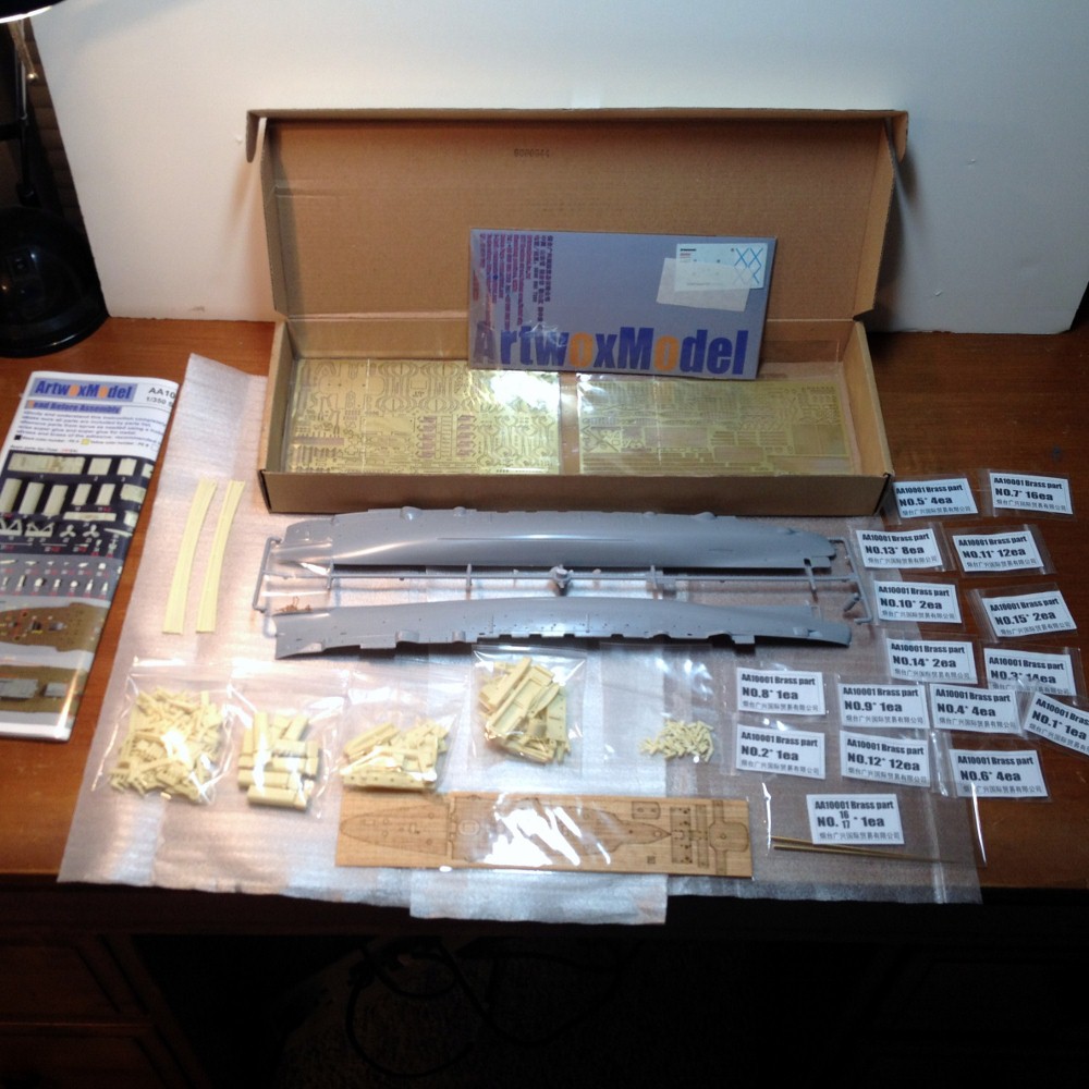
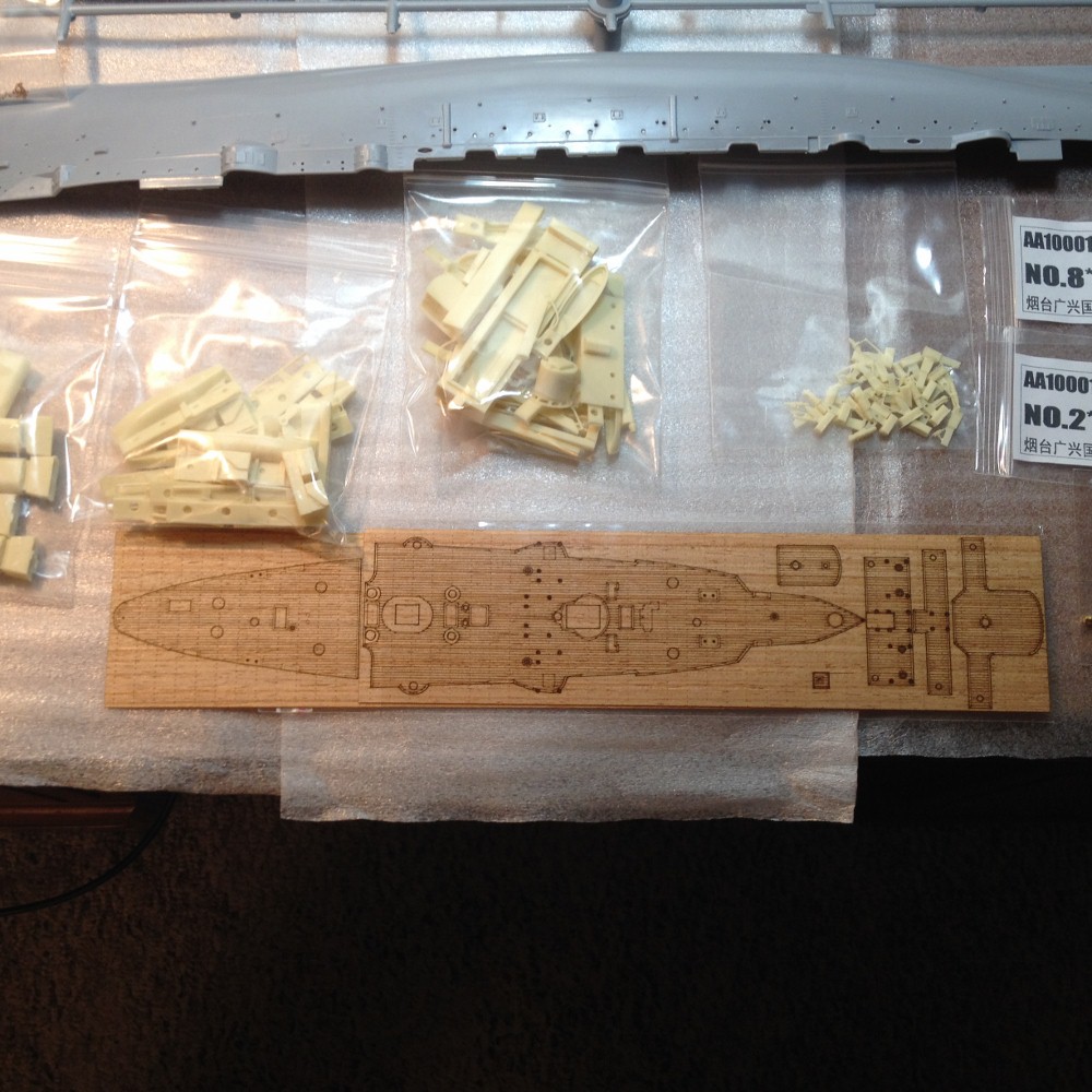
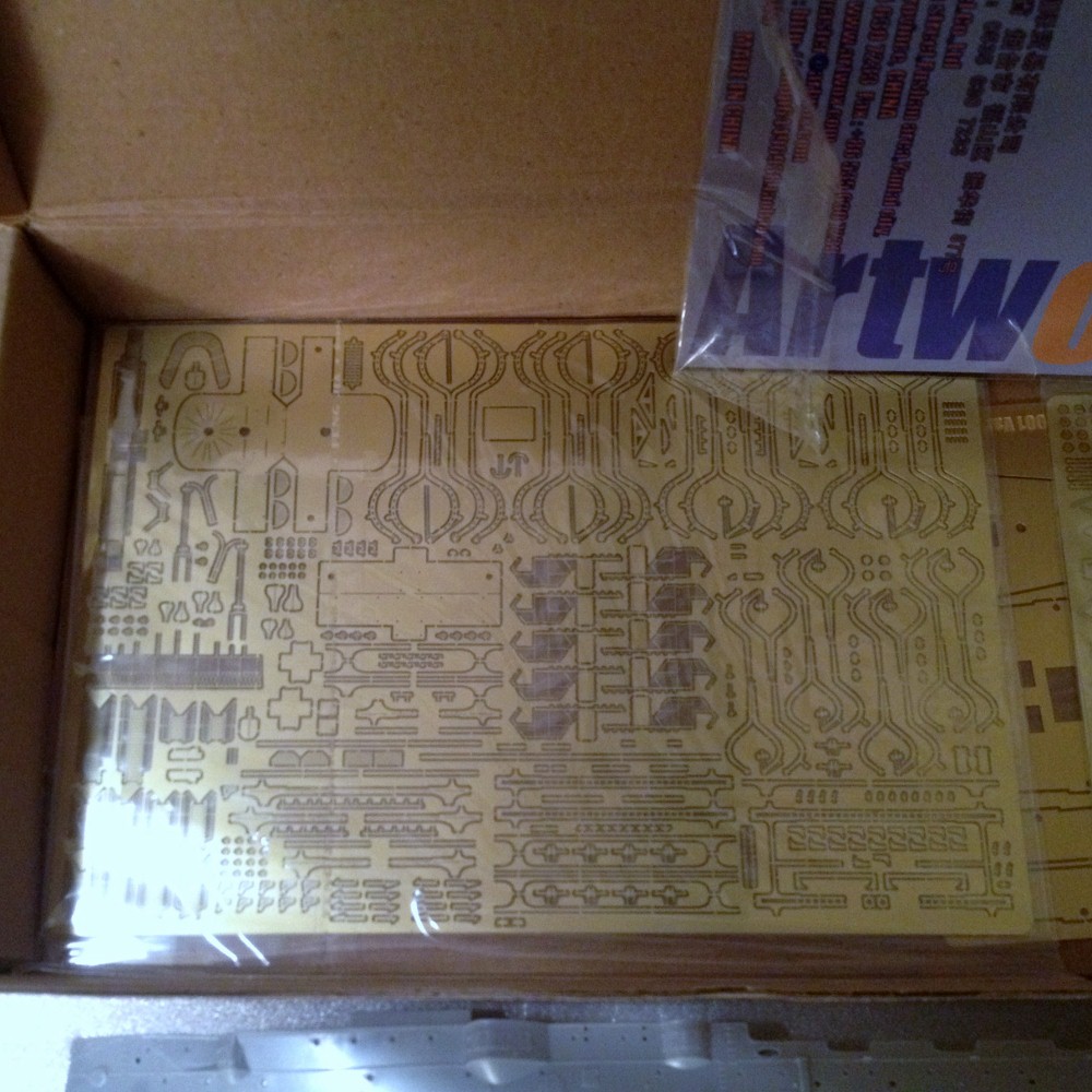
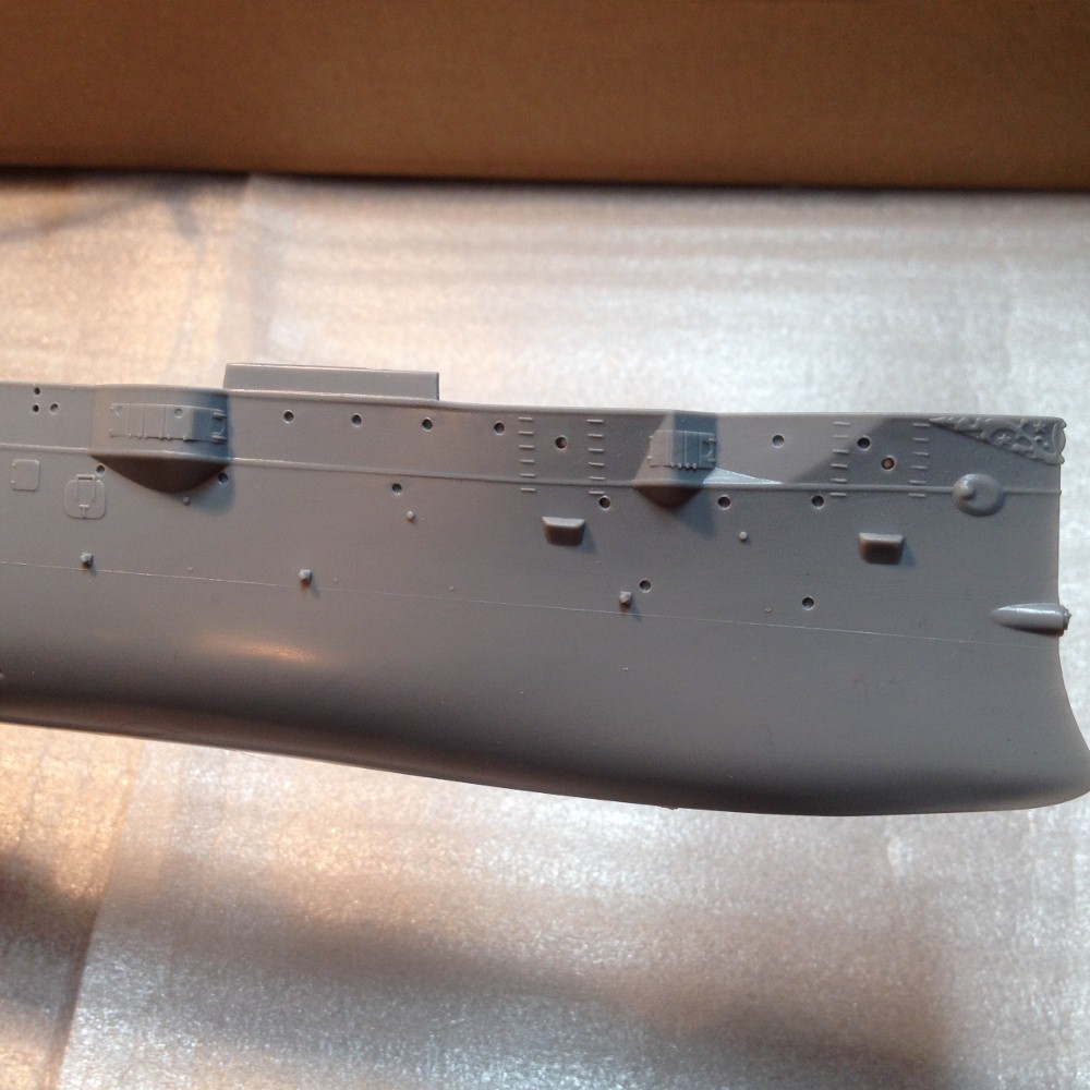
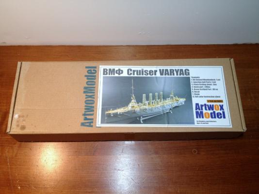
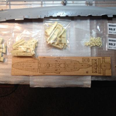
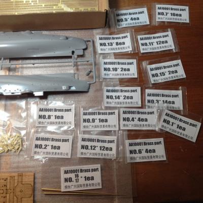
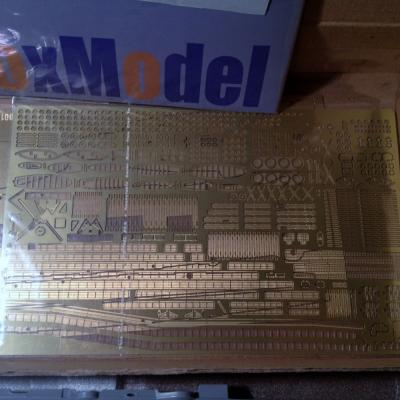
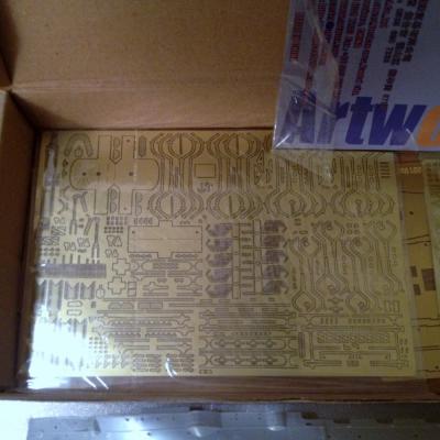
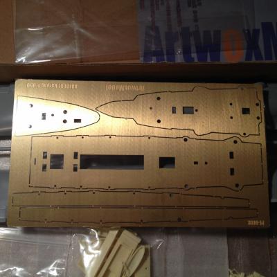
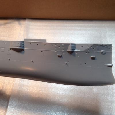
Introduction: Imperial Russian Cruiser: Varyag, (Variag) I am really excited to work on this model, having followed it's development prior to release and finally purchasing one of the last remaining kits in the USA (that I could find anyway). The kit was produced as a limited edition by Artwox Model, who are mainly known for their wooden deck offerings. This kit was their first foray into a full model kit, detailed release photographs can be found here. My interest in this kit was not originally in the actual ship itself, but rather in the type of ship, and the level of detail that the kit contains. What I was really looking for was a super detailed model of SMS Emden of World War 1 fame. However, I quickly came to realize that if I wanted to do anything to the level of detail that I wanted, I would have to scratch build most of it. Emden was appealing for it's operational history, type of ship, and the mission it was designed for. These protected cruisers were at the time not conceived of as line of battle ships, but rather as commerce raiders. Almost akin to the frigates of 100 years before. Emden and her crew played that role to perfection in the Indian Ocean. A highly detailed kit of Emden was not available, but the Varyag was. So, not knowing much about the ship or it's history I sprung for the kit, putting it in my to do pile for a later day. In the interim, I have learned a lot about the ship, it's history, and even it's crew. I plan on doing a more detailed post later on to share some of the better details that I have learned thanks to a Russian co-worker, a museum curator, and good old fashioned research. Some Quick Facts: Built: Philadelphia Pennsylvania, USA, William Cramp & Sons Year Launched: 31 October 1899 Type: Protected Cruiser Length: 425' Beam: 51' 10" Draught: 20' 8" Armament: 12 single mount 6" Rifles 12 single mount 3" Rifles 10 Small Caliber, 1.9", 1.5" rapid fire Rifles 6 Submerged Torpedo Tubes, 15" Service: Russia: 1899 - 1904 Japan: 1907 - 1916 Russia: 1916 - 1918 Fate: Seized by the United Kingdom 1918, ran aground 1920. scraped 1925 The Kit: Whats in the box: as you can see from the photo above, there is a lot in the box! The hull is a casting from Zvezda, the deck is a thick sheet of brass covered by a real wood veneer. Everything else is either in the 248 pieces of resin, 86 scribed brass parts, or in two large sheets of PE. Wood Deck + Some of the resin parts Brass Deck Substrate Scribed brass parts PE sheet 1 PE sheet 2 Hull Detail Kit Short Comings: Though at first glance, it appears that everything you could possibly want to build the kit was in the box, that isn't really the case. For one, there is no stand or mounting contained in the contents. Okay no big deal there. The other, the instructions, though highly detailed, only show you where everything is supposed to end up in the assembly. Not how to put the ship together. So I hope that this log can be of service to others that may have a hard time deciphering the pictorial instructions. The next post will include some history and research about the ship, then I will get into the build itself. Best Regards!


- 5 replies
-
- 10
-

-
- varyag
- protected cruiser
- (and 2 more)
-
Very nice! Great smooth planking job.
-
You are off to a good start! Have you ever seen Howard Chapelle's book, The History of American Sailing Ships? There are some great illustrations of the Rattlesnake on pages 137 - 143. You can find the book here if you like: Link to Amazon.com Page Good luck, and remember that mistakes are tools for learning. Most of all have fun with it. Regards,
-
Thanks Alistair and David! Alistair - I will look into the bolts. Thank you for providing the link.
-
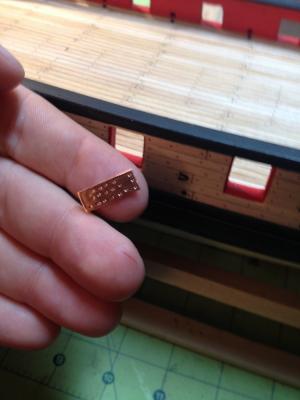
Thank you everybody! Josh - Thanks for stopping by, Enjoy the kit, it produces a wonderful ship, solid with nice lines. I in fact do have a nice little project lined up for the little boy and I to enjoy. I will be posting on it later in the summer. Thomas - You are correct about the center casting. I didn't even realize it until I read your post and checked the pictures in Chuck's practicum. It should have stood out to me that the garland was defying gravity, but alas it did not. At this point, I am okay with it, and being that it is glued on with CA, I do not want to go through the trouble of taking it off and making the wood underneath presentable again. It will be a great reminder to pay attention in the future. Thank you for pointing that out. Robert - Thank you! I hope you stop by again. Michael - The center of each "nail" is raised for the most part. This was accomplished by burnishing each plate with a pencil eraser. It creates an effect similar to a nail head and washer. I did experiment with stamping from the paper side, but I did not have any luck with it. I suspect, that if it were tried on a hard, yet semi forgiving surface like a cutting mat, it might work. I was trying it on basswood with pins that were way to big to start out with. I just could not get a reliable pattern out of it stamping through the paper. I do not think it impossible though. Thank you for suggesting making the plate series a how to post. I may take you up on that suggestion as time permits. Best Regards,
-
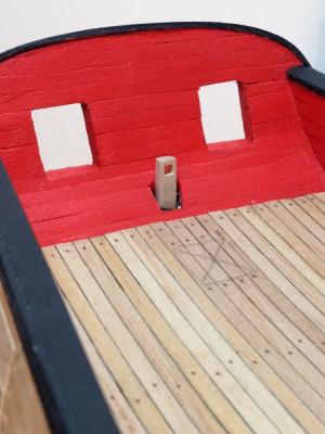
The Current State of the Build: The Syren, with a woodcut of Dr. Warren of Bunker Hill fame looking on...
-
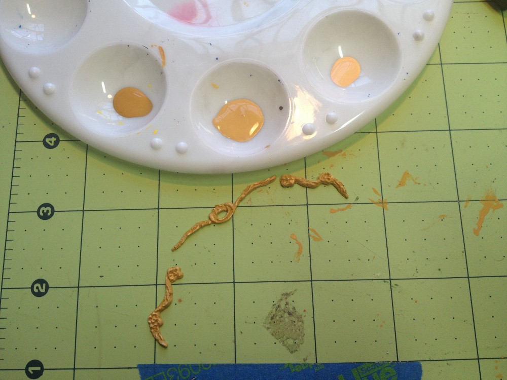
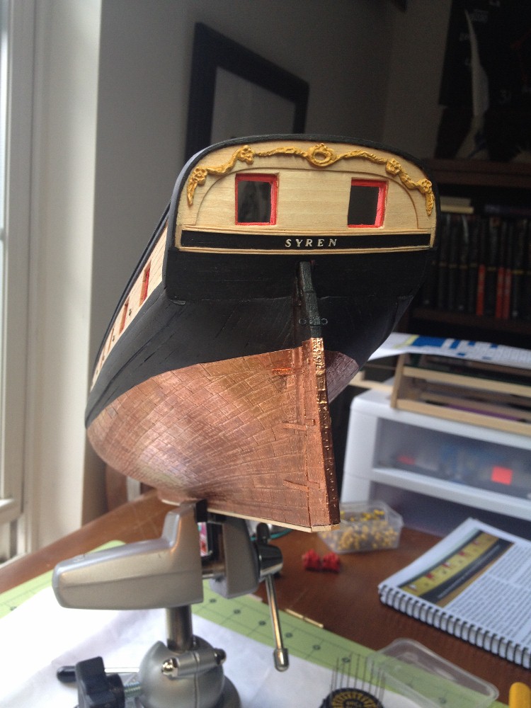
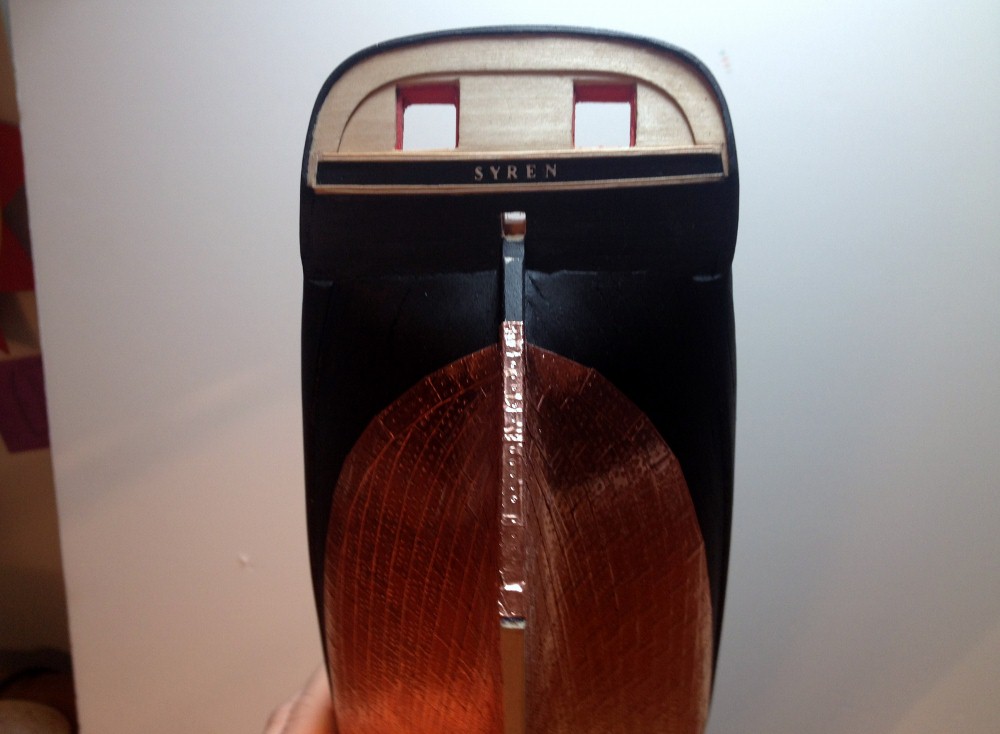
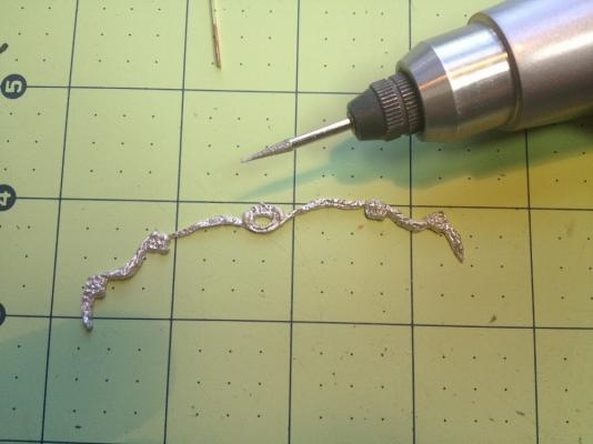
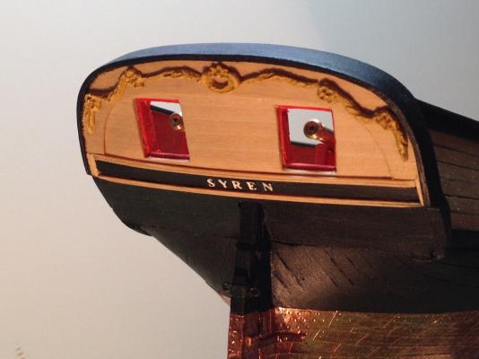
Rudder and Transom Decoration: I have had the rudder mostly complete for some time, but I have been holding off on installing it, because I just did not feel up to the task of fabricating gudgeons and pintles. So I decide not to do that. I have created simulated gudgeons, but there are no pintles on this model. For the sake of durability, I decided to pin the rudder to the stern post using three, 0.072" brass rods. The rods were inserted into pre-drilled holes in the rudder, then used to mark the locations in the stern post. Once those positions were located, corresponding holes were drilled in the stern post. Everything was then press fit together. The small rods were just flexible enough to allow for some fine tuning to get the rudder straight. Before I hung the rudder, I decided that I would create a mortise in the rudder head to accept the tiller when it is installed. I used a drill bit that was the correct size, then used a 2mm micro chisel to square the hole. Initially I only made the mortise a little more than half the depth of the rudder head, but then decided to go the whole way through, to allow the tiller tenon to pass through the rudder head to be fidded on the after side. I also installed the carved moldings along the transom. I decide to use the kit provided castings, as I do not feel the call to learn carving at this point. I started by cleaning the castings up with a burr grinder and added some detail. Next I painted them. In order to give them maximum effect, I painted them with a three tone scheme. A base color, a slightly darker color for the low spots, and a slightly lighter color for the high spots. This provides the piece with added depth, and makes it look closer to carved wood. Finally I attached it to the transom.


-
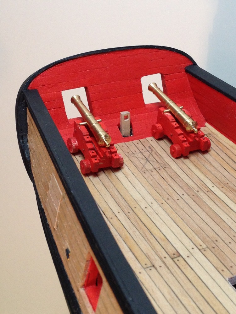
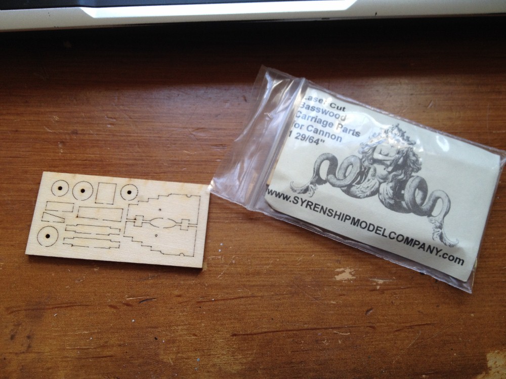
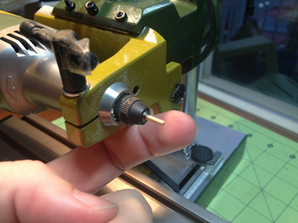
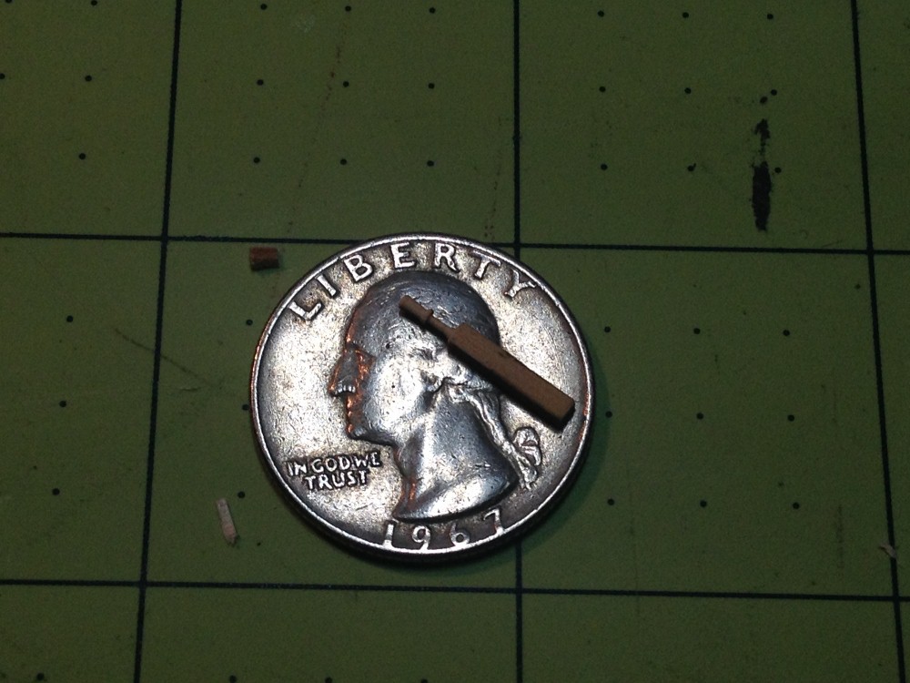
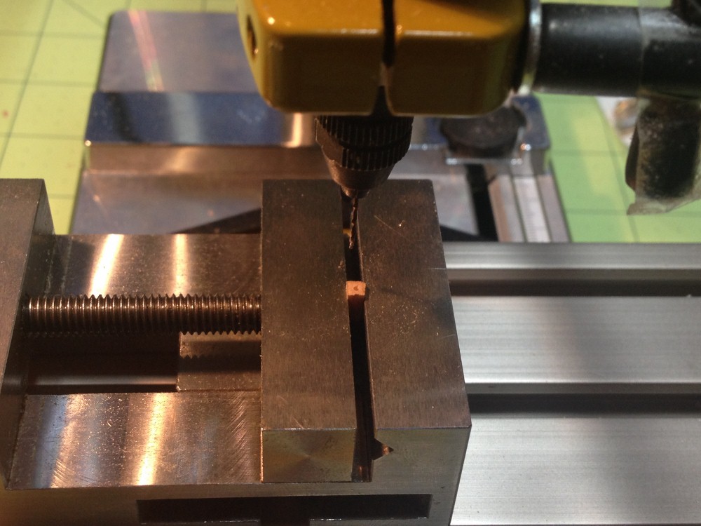
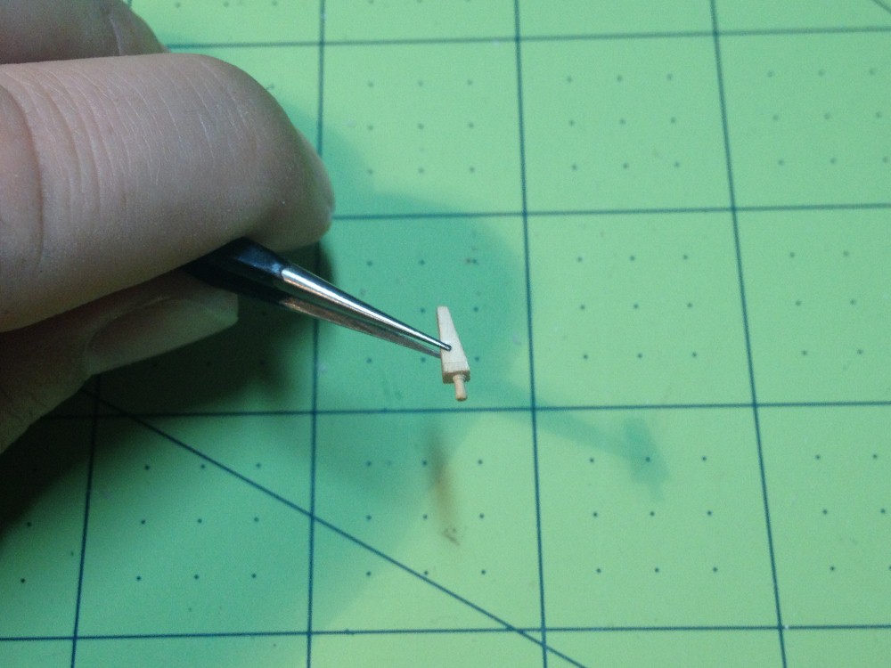
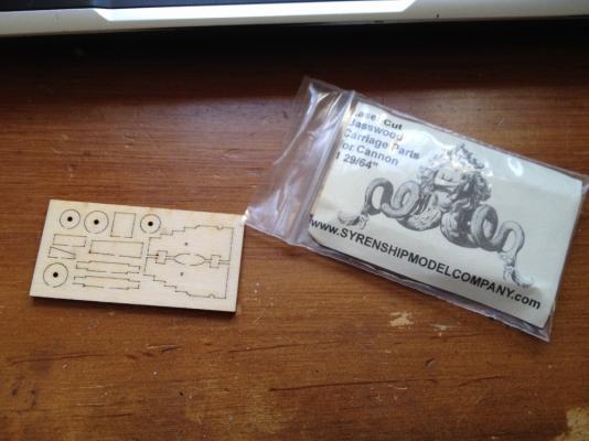
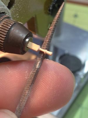
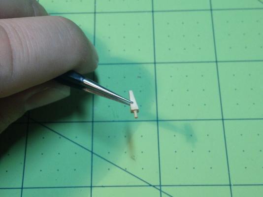
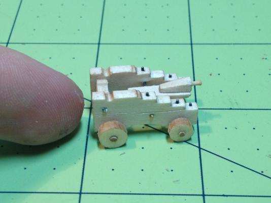
Twelve Pounder Chase Guns: One of the first things that I was able to do after life started to slow down a little bit, was to start on two really small models. I purchased a gun carriage kit form Chuck Passaro's Syren Ship Model Company. I also purchased the beautifully turned brass 12 pounders to go with them. I had so little time to spend on modeling in March, April and May, that these little models gave me the 5 minute fix that I needed every so often to keep me involved in the hobby. I was very pleased with the products offered by the Syren Ship Model Company. I have also since had the opportunity to try their blocks and rope, which were of equal quality. I bought these pieces to replace the kit provided 12 pounders, though the kit long guns really are not that bad compared to the carronades that are provided. I made the decision to use an all turned brass armament as a matter of taste, and as a matter or accuracy in the case of the carronades. The downloadable instructions on the Syren Ship Model Company's website were easy to follow, and provided a clear path to not only put the pieces together, but also to add a few details to make the finished carriages all the more realistic. Another nice touch, is that the carriage kit comes with a few pieces of boxwood stock to make pieces such as the quoin and it handle. I used a 1/16" square piece chucked into my rotary tool, and a small file to produce the tiny handles. Next I filed the quoins to shape, then drilled the correct size hole in the back of the quoin to accept the handle. I also added a few of the details suggested in the downloadable directions, such as simulated bolt heads, and the suggestion of a two piece carriage side made by scoring a line across the piece. You will notice in the picture of the completed carriage, that one of the "bolts" came through the inside of the carriage. I have since fixed the problem, being a "bolt" that was too long, and forced into the pre-drilled hole. I still have to install the gun retention straps, and associated ring bolts into the carriage, but I am holding out on that until it is time to install the finished cannon onto the deck. More updates to follow shortly!


-
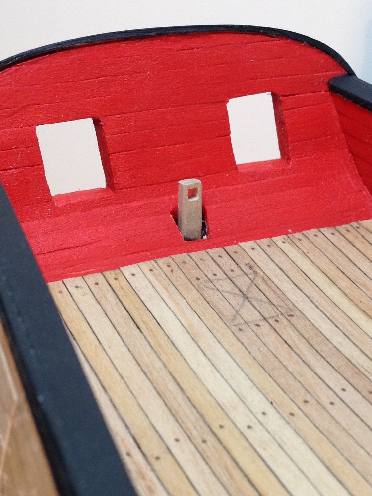
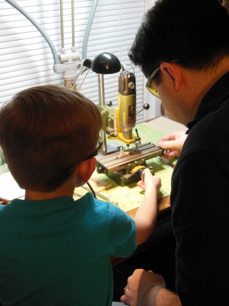
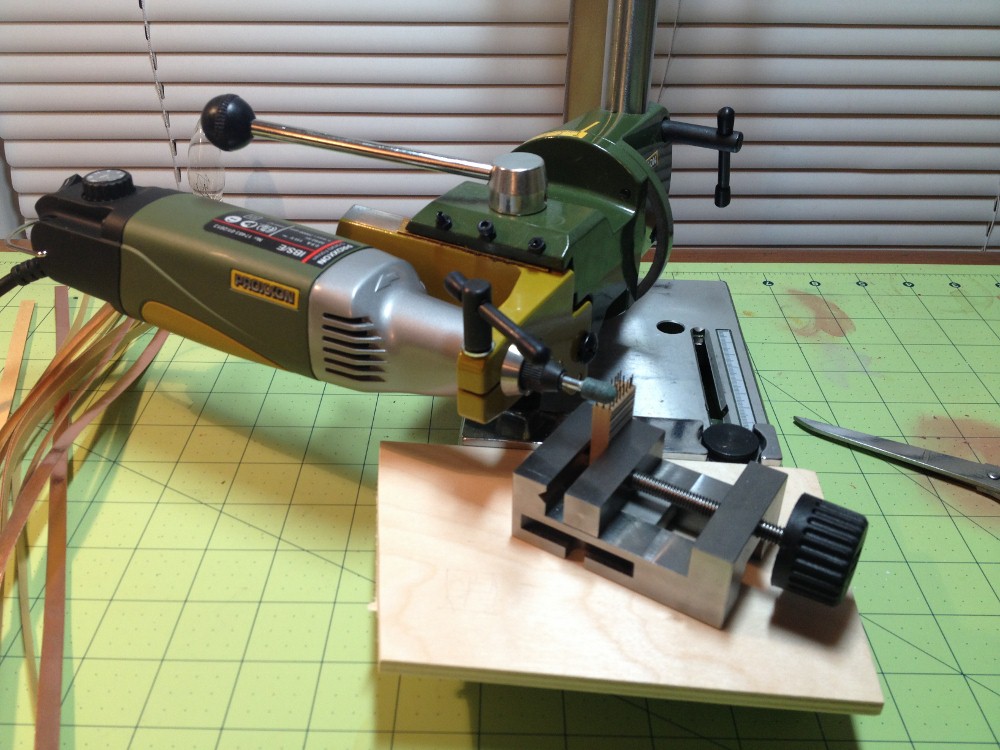
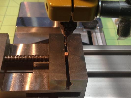
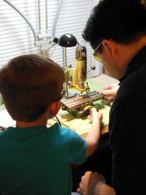
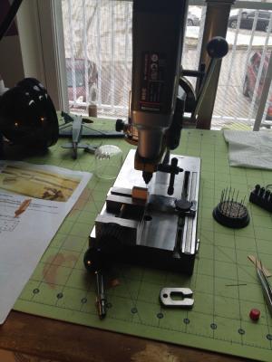
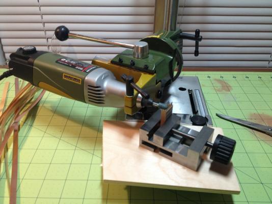
Thank you everybody! It has been a really long time since my last update! So much has happened that it has kept me from working on any models, but things are finally calming down enough to start updating the build log again! Todd, in answer to your question, I used the X/Y table on my proxxon tool stand to get a really reliable placement of each hole. The resolution on the table is 1mm per turn of each axis' control knob. So you can be quite precise! Here is a picture of the whole setup with my apprentice helping me.
-
Hello David, great start to your dear Surprise! The 1798 Drawings produced by John Marshal at Plymouth do indeed show the break of the quarter deck to be in this location. This drawing is published in the Lavery and Hunt text. It can also be found here: http://upload.wikimedia.org/wikipedia/commons/9/91/Plan_of_HMS_Surprise.jpg I think it is pretty clear in this plan that there is a break between the quarterdeck and the gangway. What is not clear, is if there is a similar break between the gangway and the forecastle. Later on in the Lavery text, the drawings produced by Marquardt again show the break at the quarterdeck, but they do not show a break at the forecastle. The location is correct according to both the Marshal and the Marquardt drawings. Happy Modeling!
-
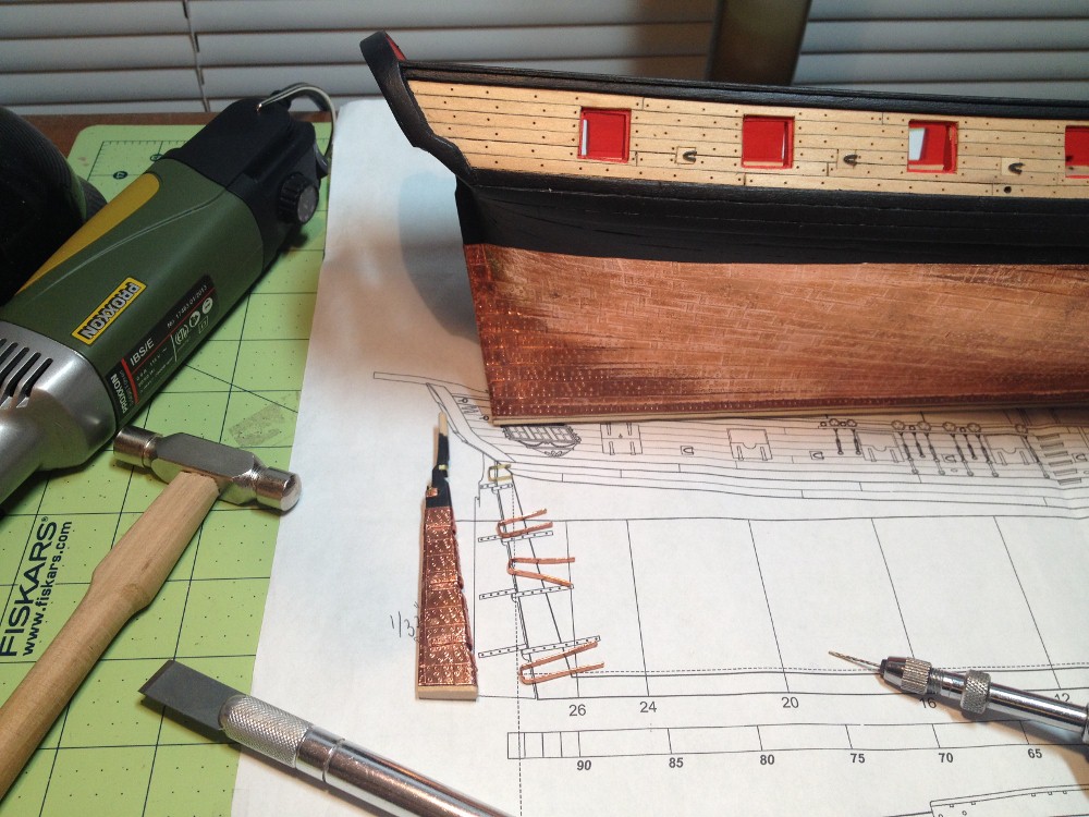
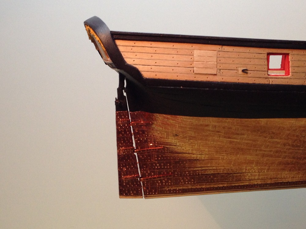
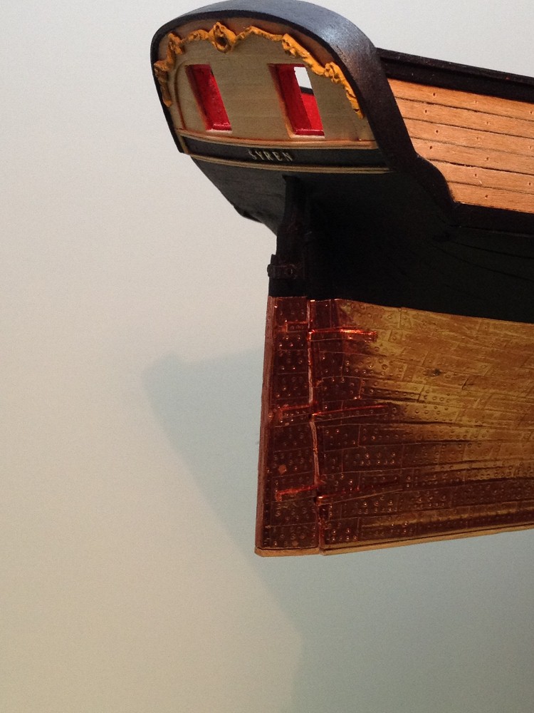
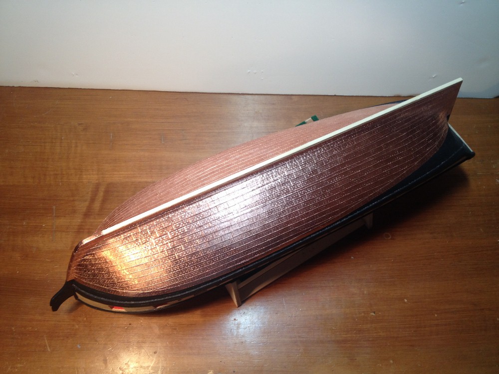
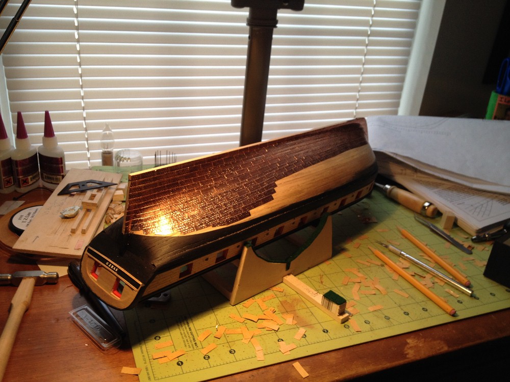
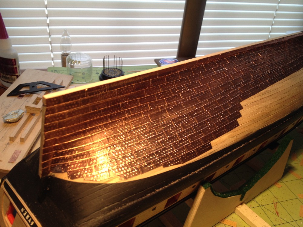
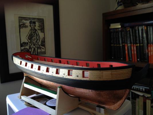
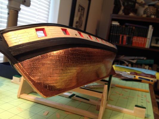
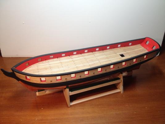
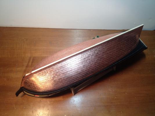
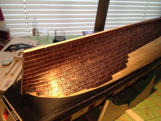
Copper, Finished at Last! This had to be the most tedious part of this build up to this point. However, the result is really satisfying. I am not sure I will ever copper the bottom of a model again, but I am glad that I finished this one. I have to say, that the day that I bought this kit, I opened the box to examine the contents. At that time, I was not sure I could ever get to this point in the build. As you can see from the last photo, I have started to prepare the ship to receive the rudder. This was a very nerve wracking step, as I did not want to wreck the counter.


-
Truly amazing work! Absolutely incredible!
-
Thank you B E! Marsares, I am indeed using the IBS/E, MB200 tool combination. To this point in time they perform very well. Both of them are obviously built to a high standard of quality, which is apparent the moment one lifts the tools from their packaging. The Drill stand in particular is very durable. When I started using the MB200, I was a little concerned about being able to adjust the height of the tool. However, I have found with use, that the height adjustment mechanism works well with very little play. There is one adjustment that has to be checked regularly, and that would be the tension adjustment on the press slide. On the picture above, where the tool is being used to grind , you will notice three small, black, hex nuts. These keep tension on the slide, and if they are not cared for there will be some play in the slide. The IBS/E is by far the best rotary tool I have ever used. Again, there is a sense of durability imparted by the feel and weight of the tool. The rotational speed adjustment is smooth, and the rotation lock for changing bits is well designed. It also comes with a set of 5 collets of various sizes. However, anything smaller in diameter than say a # 70 drill bit will need an additional collet. I will be picking up the KT70 table in the coming weeks as well, I think the combination will make a quality, versatile tool for a modest sum. I hope that helps! Regards,
-
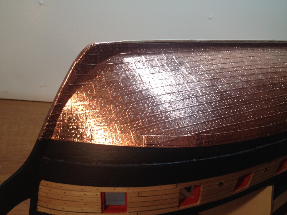
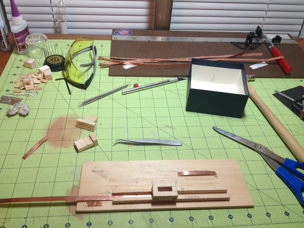
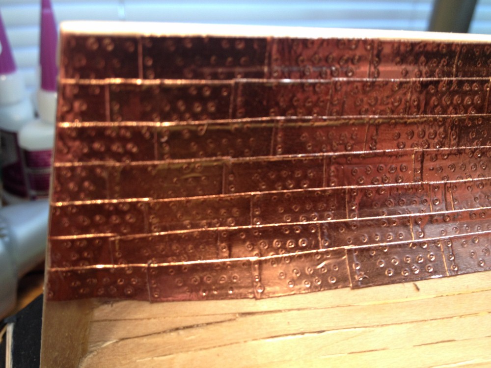
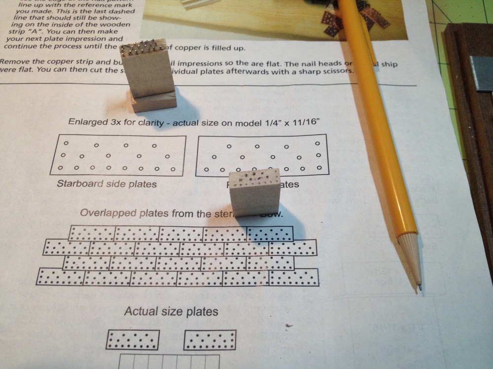
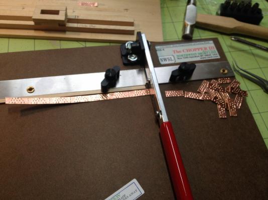
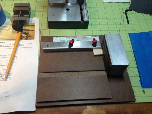
Plate Production: After getting the stamps squared away, it was on to the production of plates to cover the underwater hull. As I wrote above, originally I wanted to create the relief of the stamp above the surface of the plate rather than emboss the simulated bolts into the plate. I thought that this would simulate the appearance of nail heads or bolt heads in a more realistic way, However, in practice all that I was able to accomplish was a mess. So I went into plate production stamping the plates on the copper side of the tape. To start I cut 16" strips of copper tape, and then straightened them by running them through my fingers until the curve from being coiled was taken out. I marked the stamping jig with a stop line, so that I could advance the tape through the jig and stamp it without any waste in copper. After the strips were stamped throughout their entire length, I cut them into the individual plates using a chopping machine. When I started to apply the plates, I was pleasantly surprised by something unforeseen. While applying each plate, I burnished them with a pencil eraser. No only did this get the plate to stick to the planking very well, it also produced an effect on the stamped pattern that was very welcome. The burnishing process raised the center of each simulated nail head, while leaving the perimeter of the circle indented below the plane of the surface. The visual effect produced is much like the head of a fastener surrounded by a large flat washer. I am not sure if this would be correct on the real thing, but since we are really just simulating a pattern in a scale that would be extremely difficult to produce a truly accurate pattern, I think the produced effect is a credit to the model. Up to this point, I have coppered the port side. I will continue with the starboard and dressing belts next week.


-
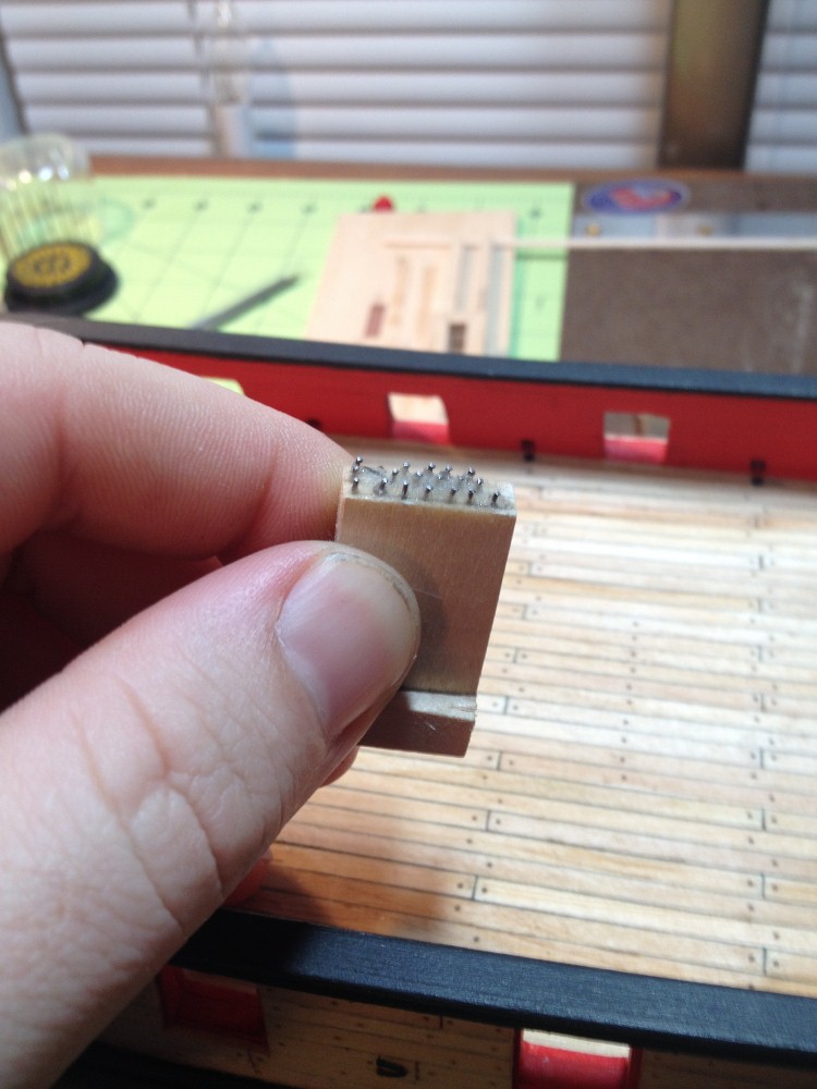
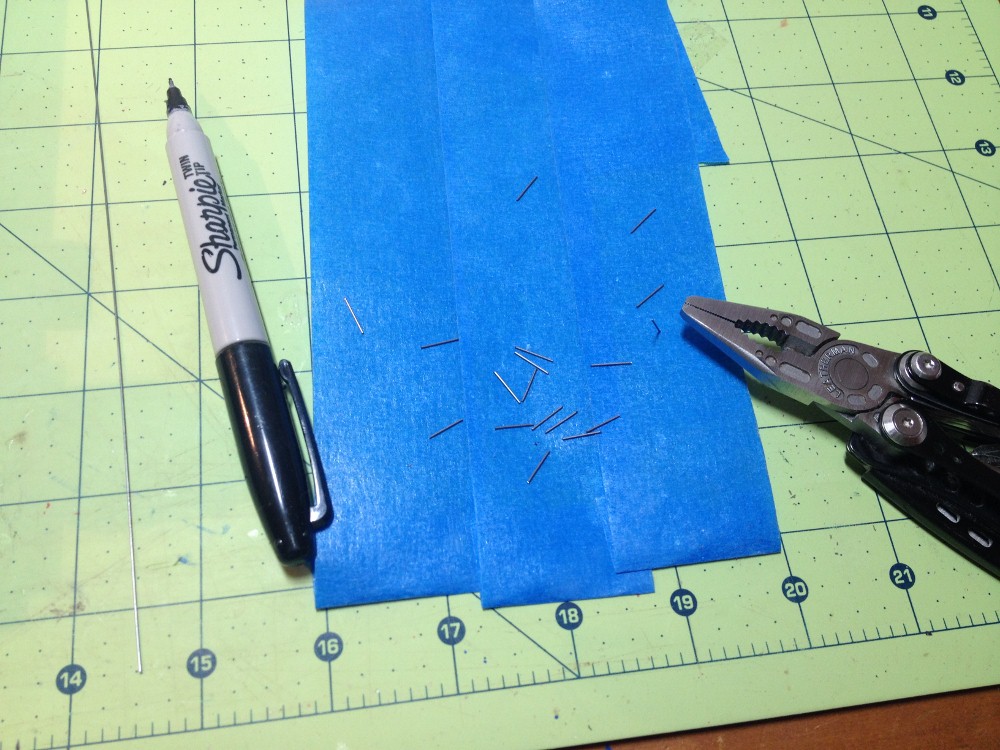
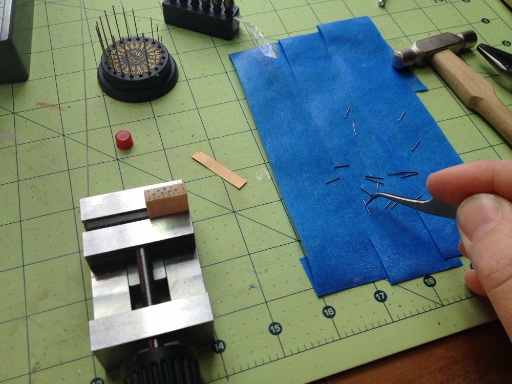
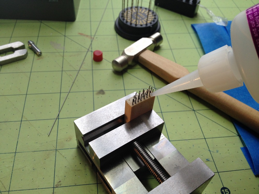
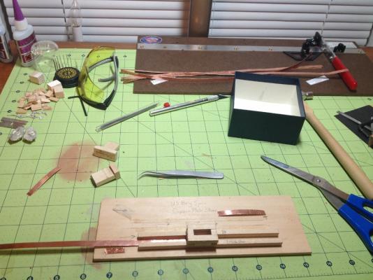
Copper Sheathing the Hull Wow, this stage of the build gave me a lot of troubles. I was dismayed to see that the last time I posted to this thread was in November! The biggest problem that I had in starting this stage was the construction of an appropriate stamp. After somewhere near a half dozen attempts, I put the project aside to ponder how to solve the problems encountered. When I started this stage, I decided that I was going to try something a little different. Chiefly, I wanted the stamp to create a relief above the plate, rather than an impression below the surface of the plate. Therefore I started by stamping the plates from the paper side of the copper tape. Two problems surfaced rather quickly. The first being, that the force required, and the large diameter of the pins I chose, caused the backing to separate from the copper. The second problem, was that I was not getting a clean impression, some pins were not leaving any trace of their existence on the copper. The first fix was to try to get all of the pins to leave an impression by sanding, then filing the pins to the best of my ability. I tried a variety methods, but unfortunately I did not posses the necessary skill to make a perfectly flat plane across the tops of the pins. I also realized that my pins were at very disparate angles with reference to the the wooden block of the stamp. I do not think any of them where at 90 degrees from the block! I should note before moving on, that I coppered about 1/4 of the port side with my original stamp before I got so frustrated that I removed it all. In the hopes that I may save others from some of this same vexation, I will lay out how I came to construct a stamp that I believe works pretty well. First, I realized that I needed a means to make all square. Doing all of the work with the hand tools at my disposal, was just not going to produce the results I wanted, so tool shopping I went. Second, as mentioned before the pins were too large. I settled on a 1/2 mm steel wire to make the impressions. So let us begin, After cutting the block of wood that would make the body of the stamp, I used this true sander to create square edges on all faces of the stamp body. If I could get away with it, without getting nasty complaints from the downstairs neighbor, I would have used a disk sander. Next, I marked out the stamp pattern on the stamp face with a pencil. Then, I cut the pins with my leatherman tool. It has a really great wire cutter on it. In the picture, you will see the blue painters tape on my work surface. The tape is placed sticky side up, so that when I cut the pins to their measured length, they stick to the tape rather than flying off somewhere. Next, the holes were drilled in the stamp to accept the pins. I used a slightly undersized bit, then lightly tapped them in with a small jewelers hammer. Make sure to tap lightly and feel for the bottom of the hole, so that all of the pins are set to a uniform depth. It should be noted here, that the wood block was squared to the vice before being placed under the drill, and that a depth stop was used to ensure a uniform depth for the holes. To make sure that the pins were set into the block, I poured a large amount of CA onto the top of the stamp around the pins. I let the glue cure overnight before setting the final height of the pins. After the CA was cured I set the rotary tool at 90 degrees to the pins, using a grinding bit and several passes, I produced a stamp that I was happy with. All of the pins were perpendicular to the stamp, and all set at the same height above the surface of the stamp. Next time, on to plate production and installation!


-
Fantastic work all through your log, this stove is truly remarkable!
-
Thank you everybody! Chuck, it was a very enjoyable kit to build! I would recommend it to anybody who has an interest in wooden ship models.
-
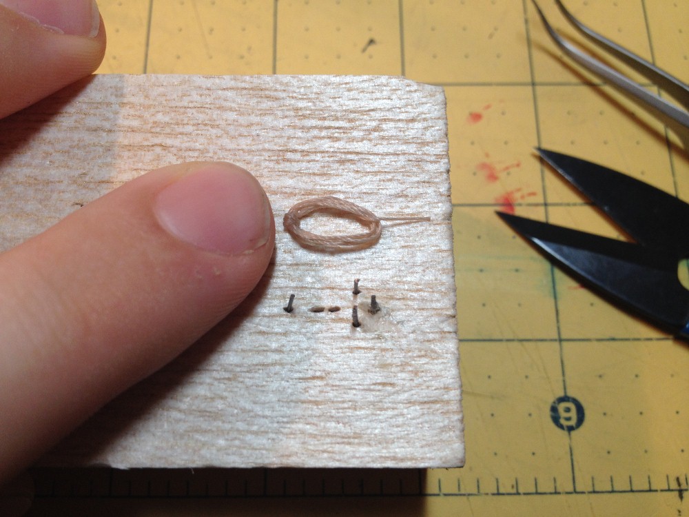
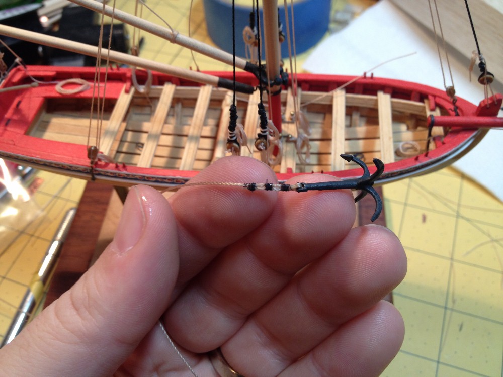
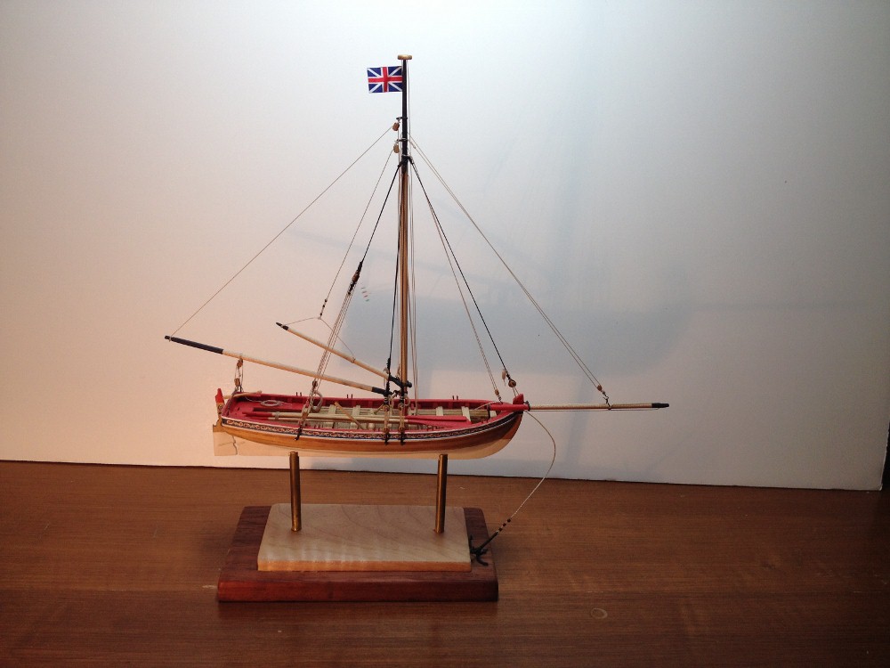
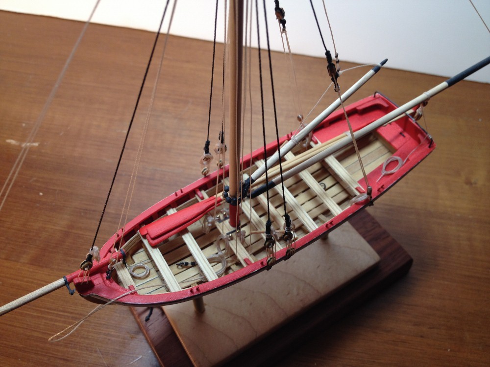
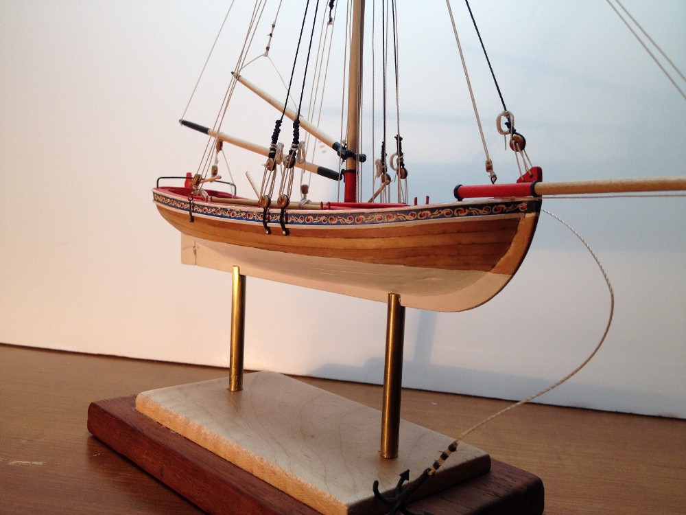
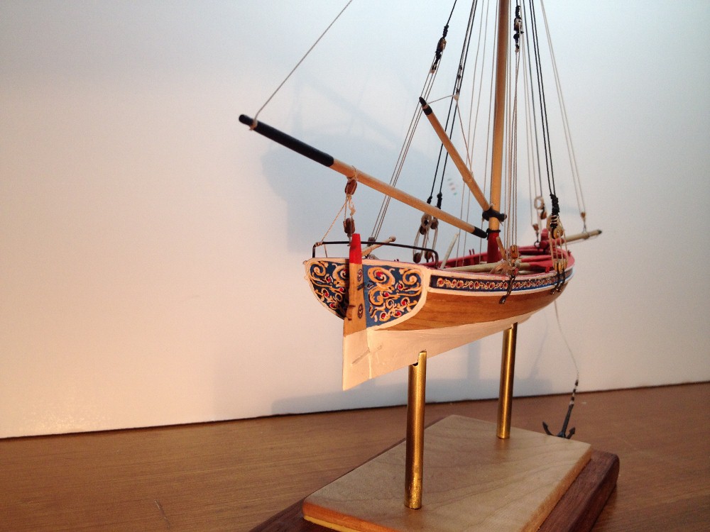
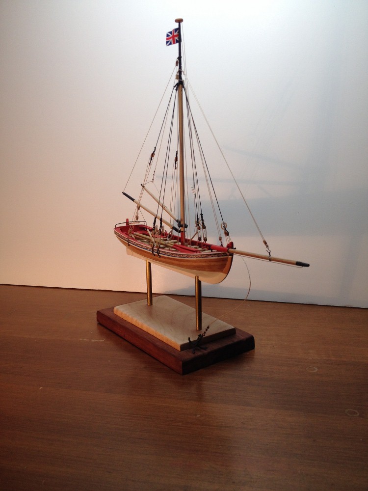
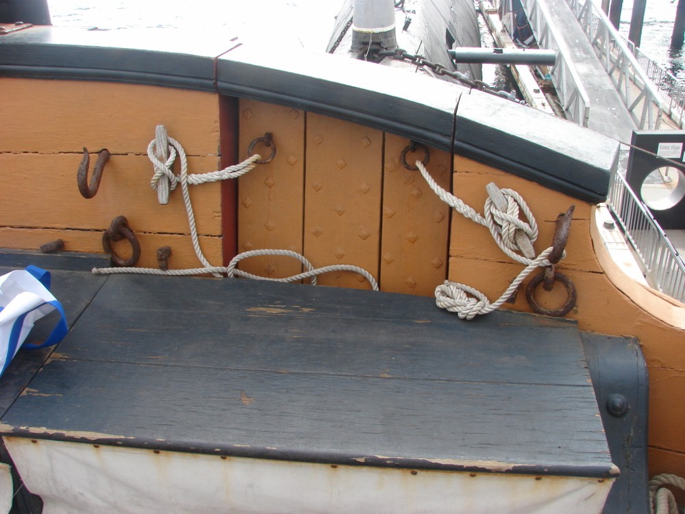
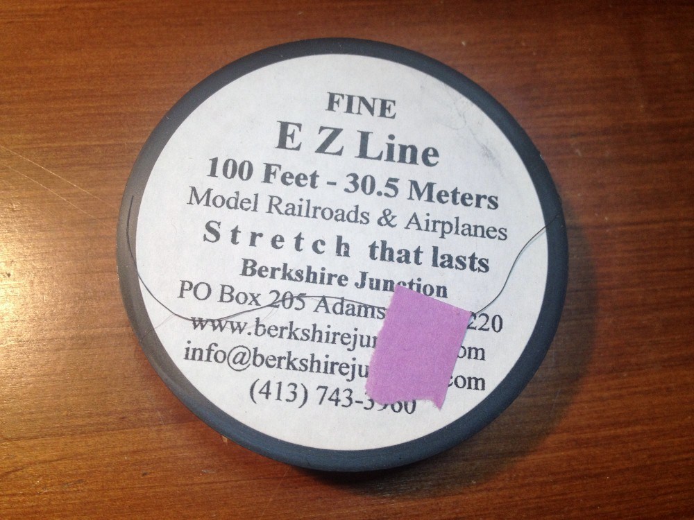
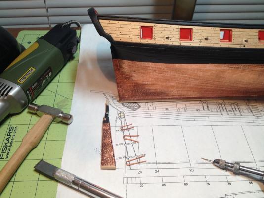
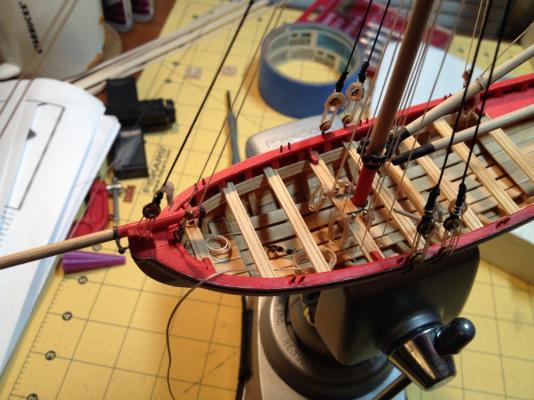
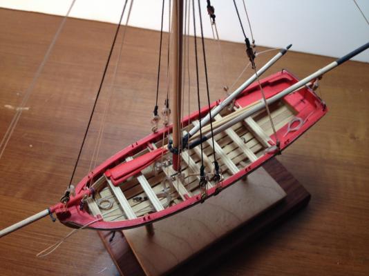
Finished at last ! So after a ship building detour to the Syren, I have finally returned to the longboat over the Christmas season with the intent on finishing her. I was stuck for a long time, since the 10th of June 2013 to be exact, on the last little details. The rope coils were particularly troublesome to me, and it took me weeks to try again after the first failed attempts. I found a great resource here in another thread on Model Ship World, and be using that along with a few modification I came up with some satisfactory coils. Here is a picture of the jig that I used to create the coils. A strand of thread was started at the right of the jig, then the thread was wound clock-wise around the jig back to the beginning, where each loop was secured by a drop of CA. After the thickness of the coil was satisfactory, I snipped the thread off at the left of the jig leaving about 2". After the coil was removed from the jig, the thread at the right was given a few turns around the coil to simulate the attachment to the belaying point. The thread off to the left was brought around behind and through the coil and glued with a drop of CA to the bottom of the coil to make it lay flat. The last step was to trim the bitter end to length. NOTE: the picture shows the coil turned 90 degrees from how is was placed in the jig: Another detail that I experimented with was "seizing" the anchor rope to the anchor and to the forward ring bolt in the boat. I used a product called EZ- Line from a company called Berkshire Junction. This stuff is pretty amazing in that is is very easy to work with, and stretches up to 5X it's static length without putting stress on the points it is attached to. I am using it to rig a plastic steam powered ship now with some really delicate masts, and I can stretch the rigging lines to the deck with out detectable deflection in the masts! The last step for me was to make up a couple of oars. I inserted the blade end of the oars into the chuck of a hand held drill. Then with one hand on the trigger and another with a scrap of sand paper wrapped around the shaft, I sanded it into a round profile of the desired thickness. Using the same technique, I used a needle file to finish off the smaller diameter grips at the end of the oar. Poor man's lathe I guess! To finish the blade, I rough shaped it with a sanding drum from a rotary tool, then smoothed it out by hand. And finally, the finished product!


- 58 replies
-
- 7
-
-
- model shipways
- 18th century longboat
- (and 2 more)
-
Congratulations Ilhan! Your model is beautifully executed, and a very interesting subject.
-
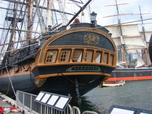
Hello Mayohoo, Thank you for posting your wonderful build of the Surprise. Especially the details you have added in the great cabin and elsewhere. I look forward to following your progress on her. As for the stern chaser ports. I did a little digging through the references that I have, and what I came up with, was yes they did as a rule have actual ports in the stern of war ships of the period. And in particular, HMS Surprise, or le Unite, had them in 1798 according to the drawings taken off of her while she was in Plymouth for a refit. The drawings clearly show the ports in the taffrail. The plans are available, I believe on the NMM website, but I got my information from my copy of The Frigate Surprise by Brian Lavery & Geoff Hunt. Additionally, and really not at all accurately, the replica ship currently named HMS Surprise has stern chaser ports. Though it is important to note, that she was not built as a replica of the Surprise. You can see them in the pictures below. Keep up the good work!

- 188 replies
-
- 1
-
-
- surprise
- artesania latina
- (and 1 more)
-
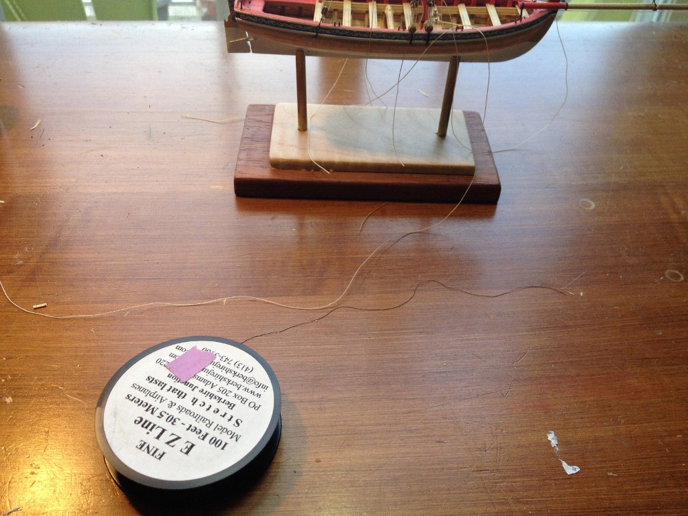
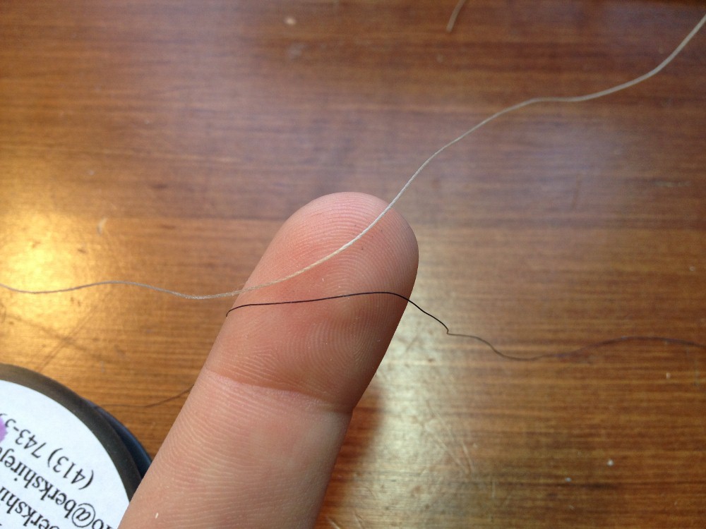
Kimberley, It comes in the following colors, black white "old copper" charcoal rust "rope" And in two diameters, fine heavy As far as the different colors of rigging, exactly what Bob said! Below, you can see fine diameter EZ line next to natural color .012" diameter thread used on a wooden model. On the pictures that I posted earlier, you may notice that one of the lines looks thicker than the others. This thicker line is just two or three strands placed together. On a sailing vessel, I am not sure I would use EZ line for the running rigging, but it is a great choice for the standing rigging.


-
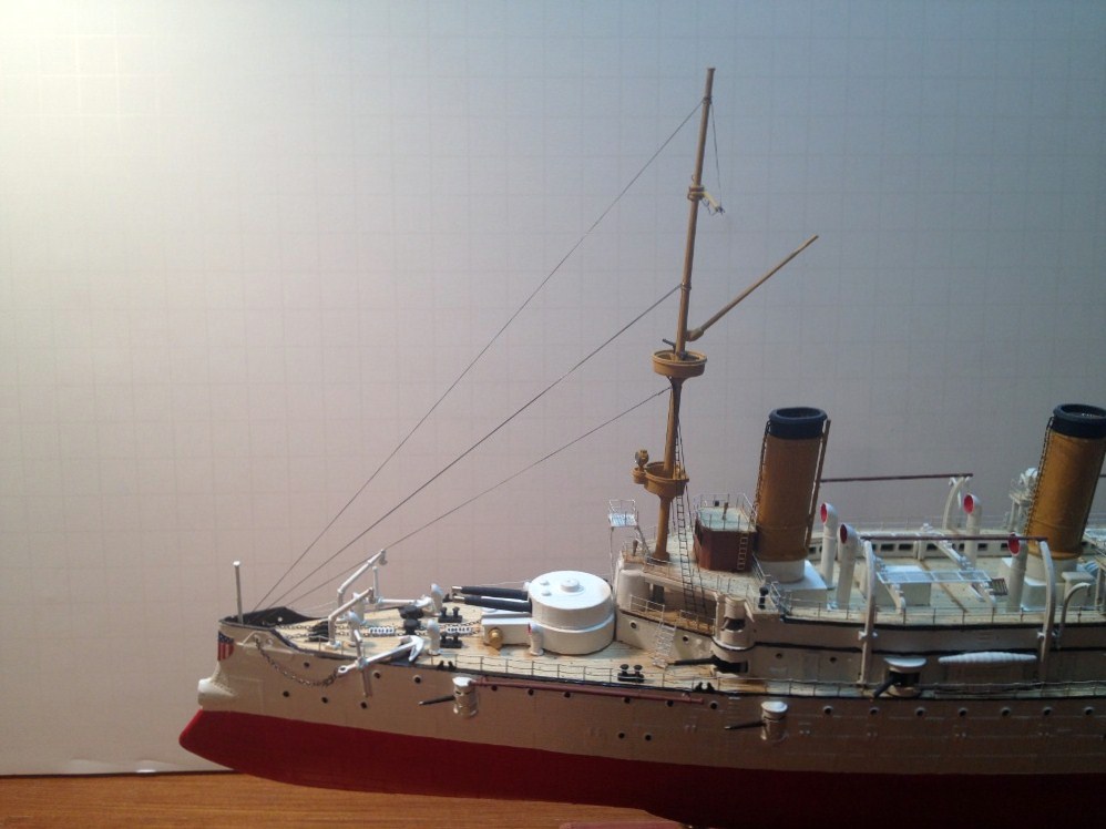
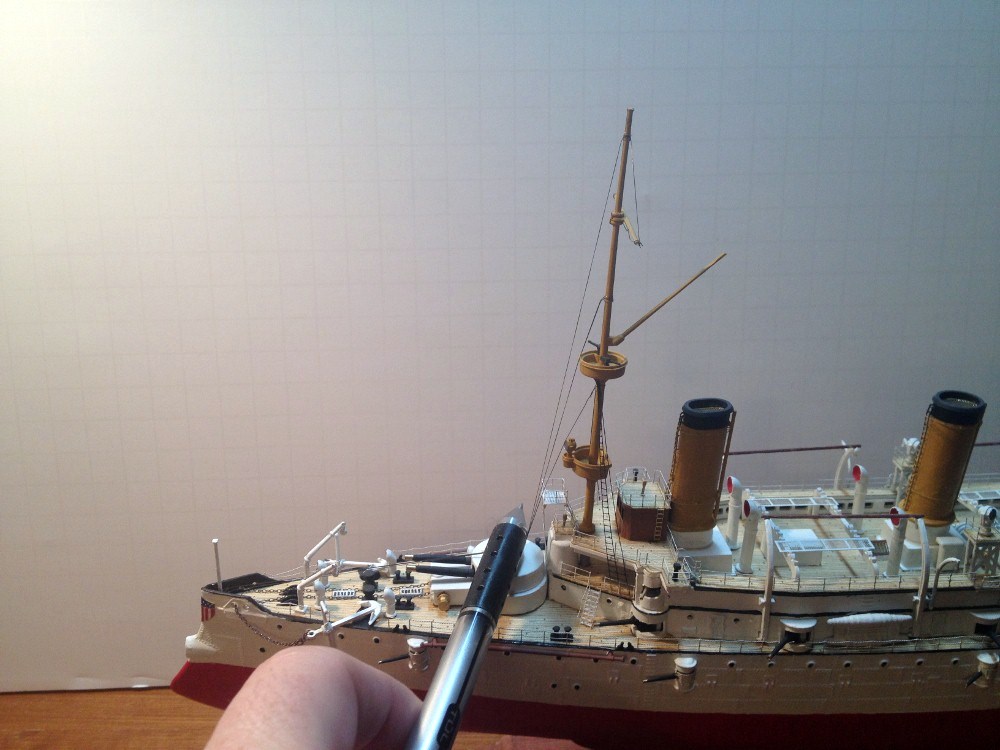
Hello Kimberley, If you are rigging a plastic ship, I highly recommend a product called EZ Line, made by a company called Berkshire Junction. You can read about it here: http://www.berkshirejunction.com/ezline.html It can stretch to several times it's static length, which is perfect for a plastic ship, since, plastic masts will deform over time when they are under tension. I buy mine from freetimehobbies.com, but I am sure you could find other sources. I am just beginning to rig another plastic ship, which you can see in the pictures below. On the second picture, you can see even if something gets caught in the rigging, it will not damage your ship. I hope this helps.


-
Thank you Chuck! I hope to be at December's meeting, as I will be unfortunately out of town for this months meeting.