
HOLIDAY DONATION DRIVE - SUPPORT MSW - DO YOUR PART TO KEEP THIS GREAT FORUM GOING!
×

David Lester
-
Posts
678 -
Joined
Content Type
Profiles
Forums
Gallery
Events
Everything posted by David Lester
-
 Hi Joshua, Thanks for the heads up, especially with the upper bulwarks pieces. In fact I have been thinking ahead about those gunports and wondering how I was ever going to get them in a straight row. The pre-cut openings are smaller than the actual openings and you're supposed to glue the actual frames individually on the inside between the bulkhead extensions. Working from the inside and between the extensions makes it almost impossible to ensure that they're in a straight row. I hadn't thought of scrapping them altogether, but now I'm beginning to think that might be the way to go. Thank you for that suggestion! David
- 59 replies
-
- 1
-

-
- prince de neufchatel
- model shipways
- (and 1 more)
-
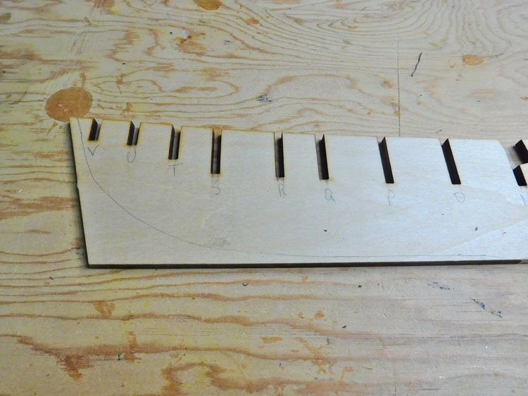
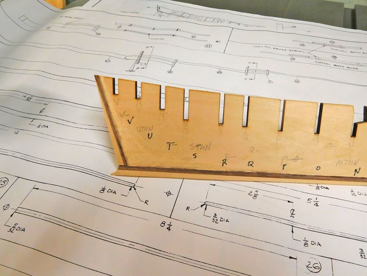
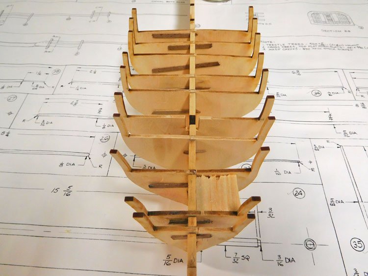
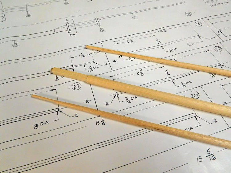
Hello Everyone, Here begins my build log for my Prince de Neufchatel. I've had this one waiting in the wings for a while, and now its number has come up. It's very early in my build and as you'll see below, my pictures aren't very interesting yet. However I have already encountered some dilemmas. I was never sure why this kit was discontinued as I think it's a particularly beautiful and interesting ship, but I am now beginning to believe that the kit needed a major design overhaul and rather than do that, they simply discontinued it. The instructions suggest that the first layer of planking should go on before the keel, stem pieces and stern piece are installed, and no rabbet be cut. I can’t see how that would work very well. I can't imagine getting a nice edge, particularly at the stem to attach the stem pieces to. And at the deadwood area, if it’s not reduced in thickness, then the first layer of planning would add 1/16” to each side of the 3/16" false keel, plus the thickness of the second layer of planking. That means the keel, stem, stern pieces and the rudder would all have to be double planked as well, which would give a pretty thick result. I decided to reduce the deadwood area, and create a rabbet nevertheless. I’ve also added the stem, keel and stern pieces prior to planking, which brings me to the second anomaly. The false keel and the stem pieces are all 3/16”, but the piece they give you to use for the keel and stern piece is much thinner and it just won’t work. So, I made up keel and stern pieces by laminating some old leftover material. I had to use a combination of basswood and walnut to get the dimensions I needed, so it looks a bit funny, but it works. My intention now is to set the first layer of planking into the rabbet, making it flush with the stern piece, but planking the stem, keel, stem and rudder with the thin second planking along with the hull. Since the bulkheads throughout the centre run of the hull extend all the way to the bottom of the false keel, I've have to reshape them slightly to allow the garboard plank to lay right. I’m hoping this will all work out ok and that I haven’t missed something that should be glaringly obvious. Now, the bulkheads – the false keel is 3/16” which is fine, but the bulkheads are only 1/8” and they are basswood, not plywood. They will be easy to fair, but they are very flimsy. Furthermore, the slots in the false keel are all 3/16”! It’s very difficult to get them positioned and I’m having to shim every one of them. I was worried that if I got them positioned inconsistently I’d never get the false deck to fit, so I did a dry fit and discovered that if I shimmed the bulkheads all in the same direction, I should be ok. We’ll see. I actually need two different sizes of shims, the parts are so poorly milled. I know there is always some tweaking to get the bulkheads to fit nicely, but this is beyond anything I’ve seen before. I’m a little concerned about what further surprises are in store; I think this will be a more challenging build that I first imagined it to be. Adding the bearding line, contrary to instructions My "two-tone" keel and stern post and deadwood area reduced the thickness of the first layer of planking. Some shimmed bulkheads installed. They will definitely need support blocks. I hope the false deck will fit. Gluing in the bulkheads is always a tedious job, so while I wait for each one to dry, I’ve been shaping the masts and yards, which is going very nicely. (Some good news.) I’m always pleasantly surprised by how good a result can be achieved with just a #10 blade and some sandpaper. Sorry this post is so long and contains so much griping. Let’s hope for shorter and cheerier next time. David
- 59 replies
-
- 6
-
-
- prince de neufchatel
- model shipways
- (and 1 more)
-
Hi Doug, Thanks for sharing your experience with this little boat kit. It will be helpful for me when I get to that stage. I have started my PdeN - (built log will begin soon, I just have to get to a point where I'm not embarrassed to photograph what I have done, and I'm not quite there yet!) Already I have discovered a number of anomalies with this kit which I'll refer to when I start my build log. David
-
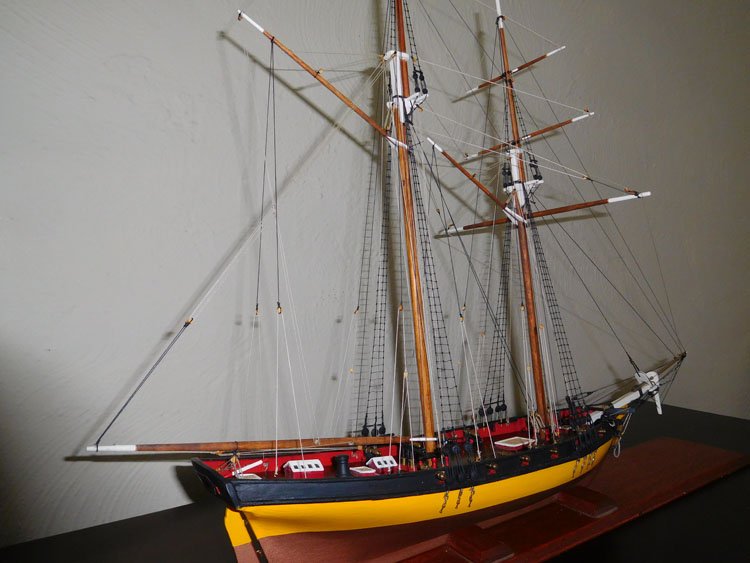
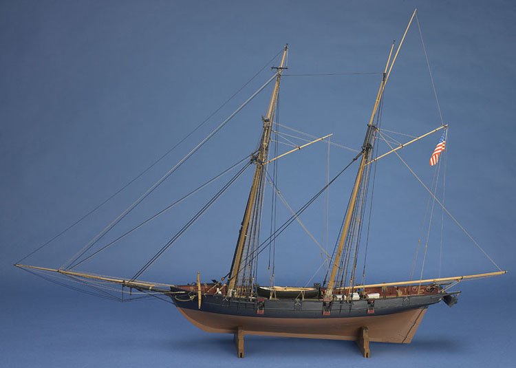
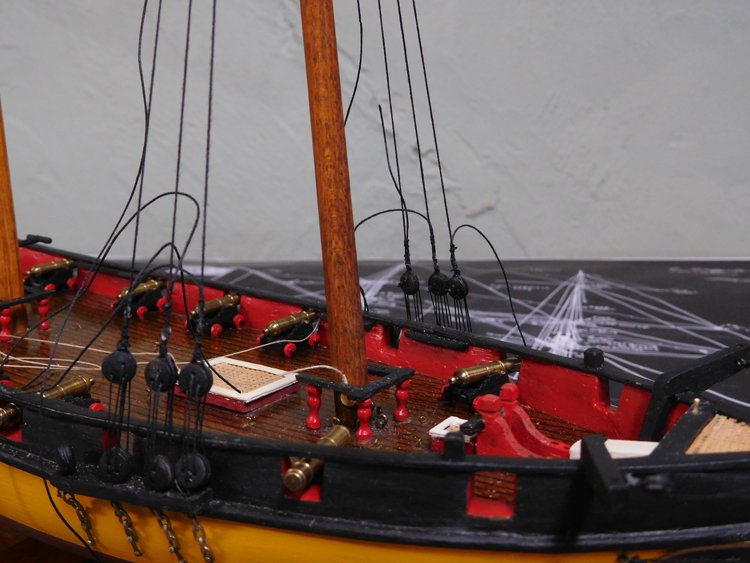
Thanks Don. I can't tell you how much having this model means to me. It's become the most prized of my growing collection. Just the sight of that black, yellow and copper hull takes me right back to when I was about 8 or 10 years old and was mesmerized by this model, (along with several others,) when it sat on one of my friend's family's many mantelpieces. David
- 40 replies
-
- 3
-
-
- virginia
- marine model company
- (and 2 more)
-
Hi Bob, I'm really pleased to hear about your PdeN! I am about to start mine. Like you I found it on eBay and I'm really taken with the beauty of this ship. So far, I have pored over the plans and have written out my list of rigging instructions to follow. I don't plan on making as many changes to the wood as you are going to make, but there are a few things I am going to change. I'm really looking forward to following your progress as we should more or less be at similar points throughout. David
- 359 replies
-
- 8
-
-
- prince de neufchatel
- model shipways
- (and 1 more)
-
I think that looks pretty good, Doug. I wouldn't be too hard on myself. Those hard bits often seem to come out of nowhere when we least expect them, don't they. David
-
Mike, thanks for the suggestions. I hadn't thought of either of those two, but they are they type of ship I like. I'll add them to my short list. David
-
Rigging Question - Virginia Privateer
David Lester replied to David Lester's topic in Masting, rigging and sails
In the end, I decided to include the jackyard. I think it adds to the model. It appears to me from the plans, that this yard is rigging very much like a gaff with the equivalent of a peak halliard and a throat halliard. I added line running from the top end of the yard to the end of the gaff. I don't believe such a line would actually be there, but rather just the sail, but I needed to add it to give some tension and make the yard sit property. Many thanks for input on this subject. David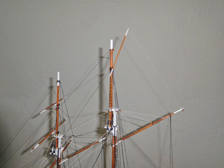
-
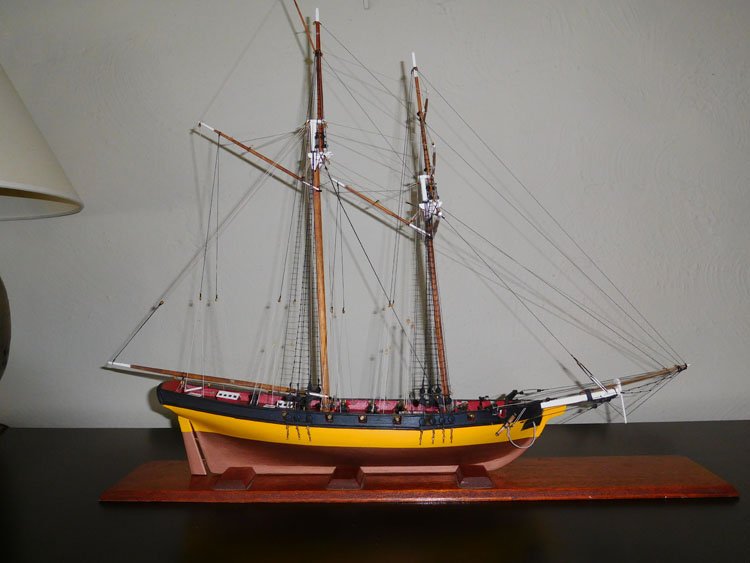
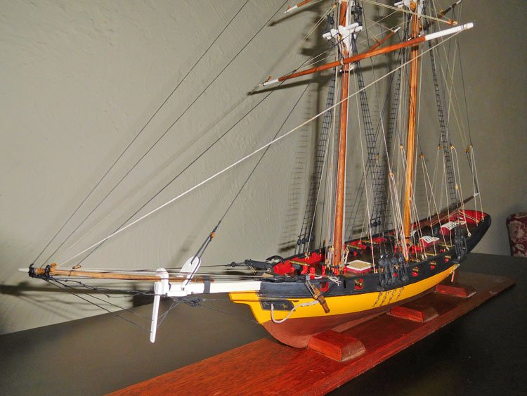
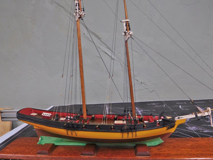
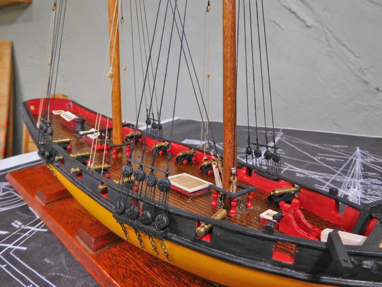
Hello Everyone, Well, I have finished my restoration of this old model and I'm reasonably happy with the result. I have to thank Bill again for sending me the plans; I don't think I could have done it without them. I've tried to keep it as similar to the original modeler's vision as possible. I resisted the urge to replace a couple of parts that I could likely have done better and I kept the paint scheme the same, even though it doesn't correspond exactly to the plan's directions. The only two major changes I made that I thought had to happen were the addition of ratlines - I'm not sure why they had been omitted - and I redrew the waterline which now corresponds to the plans. The result here is a slightly larger yellow section. Now, I will reorganize my workbench and open my Fresh Prince of Neufchatel kit and it's time to start thinking about what kit to get to have waiting on the shelf. I'm finding that I'm increasingly drawn to these American privateers, Baltimore Clippers etc, so I'm considering the Pride of Baltimore II, but my concern is that it's pretty similar to this Virginia privateer. My other thought is the Charles W. Morgan, for a real change of pace and it appears to be quite challenging. As much as I would like to build the Victory and especially since my visit to see it last September, I really don't think I'm up for another mammoth build, nor for such a massive model to have to find a spot for. So I will keep pondering and I'm sure the right answer will come to me. Thanks for the likes and comments, David
.JPG.f45acb9c862a887756cda199435c29ad.JPG)

- 40 replies
-
- 6
-
-
- virginia
- marine model company
- (and 2 more)
-
Hi Mike, I'm not sure what wood the spars are made from, but I assume it's the kit-supplied wood, so who knows? As for the colour, I like it too. I repainted the painted parts, but I left the natural parts as I found them, apart from giving them a light wiping with some mineral spirits to clean them. The spars as well as the blocks all have a slight orangey cast, which makes me suspect he used shellac on them. Also, I think shellac was more of a staple than other stains and finishes in most home workshops 50-60 years ago, and more so than it is today. So my guess is shellac, but it's only a guess. David
- 40 replies
-
- 1
-
-
- virginia
- marine model company
- (and 2 more)
-
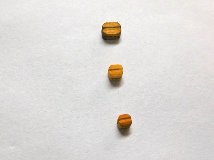
Good Morning Everyone, I'm making steady progress on the rigging. Ratlines are finished as well as the three yards on the foremast except for the braces, which I'll add at the end. Next is the fore gaff, then on to the main mast. Oh, and I have to replace a starboard backstay, which came apart due to the problem which I describe below. One frustration with this model is the blocks. They are very small. The plan indicates three sizes of block - 5/32", 1/8" and 3/32". I sorted the blocks I removed from the model into those three sizes. I don't know who measured them initially, but if I compare them to my other blocks, they are all much smaller. In the picture above, the top block is a 1/8" from my Constitution model, the middle one is this model's idea of a 1/8" and the bottom is the 3/32". They were even had to sort as the differences in their sizes are only marginal. In addition they are very rounded and I have found it difficult to seize them and have them stay in place. It's not so bad when it's still on the bench, but when it happens much later after being installed on the model it's beyond frustrating. In the end I've taken to deepening the grooves on the side with a small file and applying a dollop of glue to the sides of the block as well as the seizing. This seems to have solved the problem but even so, due to fat fingers, each one is taking me about twice as long as has been my experience on other models. However, because of their small size, they do look pretty good once in place. Not too much left to finish this model off and I do need a break from rigging. Because most of the work on this restoration has been rigging and little hull work, it feels like I've been doing rigging forever having just finished rigging on my last model. I'm really looking forward to getting started on my next one and have some wood work to do and an extended respite from rigging. David
- 40 replies
-
- 5
-
-
- virginia
- marine model company
- (and 2 more)
-
Doug, you won't have problems with it being strong enough. I made something similar for my Armed Virginia Sloop. It doesn't even have the brass support rods and it works perfectly. I'm going to build this one for my PdeN as well. David
-
Good Morning, Working on ratlines this morning, I think I've just discovered, by accident, a useful little technique. I don't know if I'm alone in this or not, but when I apply a dab of glue to the knots, I always have trouble getting a good result. No matter how dilute I make the glue or how carefully I try to apply it, I always seem to get glue on the line itself, or dabs that are too big. Sometimes it dries white and sometimes it dries a bit shiny. In the past, I've touched it up with flat black paint and the result is often a bit messy. I've finished the ratlines on the starboard side, and this morning I decided that I was unhappy with about three or four of them on each mast and decided to redo them. I applied rubbing alcohol with a small brush to the knots to loosen them. Of course, it's nearly impossible to do this without some dripping down and that's when I discovered that a very light brushing with the rubbing alcohol is just enough to take away any glued look, but nowhere near enough to loosen the knots. I when over both sets of ratlines and I've ended up with cleaner result than I've ever had before. (Of course, if after my cup of coffee I go back downstairs and discover all the ratlines laying on the bench, I'll be of a different opinion.) I don't believe that will be the case however, and I was happy to have stumbled onto this little remedy for my problem. David
- 40 replies
-
- 2
-
-
- virginia
- marine model company
- (and 2 more)
-
Rigging Question - Virginia Privateer
David Lester replied to David Lester's topic in Masting, rigging and sails
Thanks everyone for all the input; it's very helpful. I've looked at pictures of the Lynx along with many others. It seems that on a real ship when that sail is not hoisted, the yard is not there either. But on some, but not all, models without sails the modeler includes the yard. I guess is depends on how the modeler sees it. If the intention is to represent a ship where its sails are not hoisted, then you would leave it off. If the intention is to represent a ship with its sails hoisted, but for the sake of clarity on the model the sails are "invisible" then you would include it. I'll give it some more thought, but increasingly I'm leaning toward just leaving it off completely. Thanks again, David -
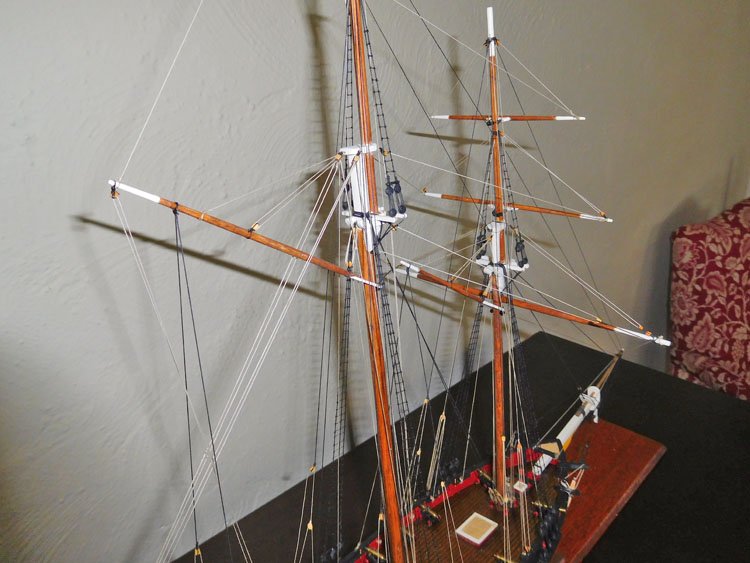
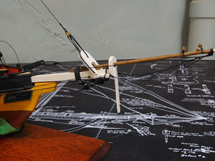
I'm beginning to believe that the rigging for this yard is actually simpler than I've been imagining. It's been suggested in my other post under rigging questions that such a yard would be raised and lowered with the sail already in place on it, which makes sense to me. I think I'll seize a block to the mast near the top and seize a line around the centre of the yard. I'll pass the line through the block and belay it to a point on the deck yet to be determined. If I'm reading the plan correctly, it appears that there is a second block seized lower on the mast and a second line seized near the end of the yard, passed through the block and then belayed at the deck as well. Although the plan doesn't show such a line, I may run one from the top of this yard to the end of the main gaff, which will put some tension on it, which may be necessary to for it to hold its position. The similar model in this photo shows such a line. Thanks again, David

- 40 replies
-
- 4
-
-
- virginia
- marine model company
- (and 2 more)
-
Rigging Question - Virginia Privateer
David Lester replied to David Lester's topic in Masting, rigging and sails
Thanks for the suggestions Lou and Michael. I'm beginning to believe that the rigging for this yard is actually simpler than I've been imagining. I think I'll seize a block to the mast near the top and seize a line around the centre of the yard. I'll pass the line through the block and belay it to a point on the deck yet to be determined. If I'm reading the plan correctly, it appears that there is a second block seized lower on the mast and a second line seized near the end of the yard, passed through the block and then belayed at the deck as well. Although the plan doesn't show such a line, I may run one from the top of this yard to the end of the main gaff, which will put some tension on it, which may be necessary to for it to hold its position. The model in the example photo a couple of posts above does have such a line. Thanks again, David -
Rigging Question - Virginia Privateer
David Lester replied to David Lester's topic in Masting, rigging and sails
Hi Gregory, Thanks for the quick reply, however I definitely don't believe that the plan is just showing perspective. The other yards are all depicted at 90 degrees while this one is shown at a steep angle. Also, in my web searching I can find pictures that suggest this position is correct for this type of ship, but they don't show how to rig it, which is my dilemma. I do have the Petersson fore and aft book, but the details are quite weak with respect to this yard. Here are a couple of examples of what I mean. Thanks again, David
-
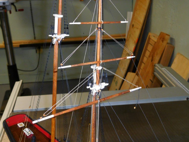
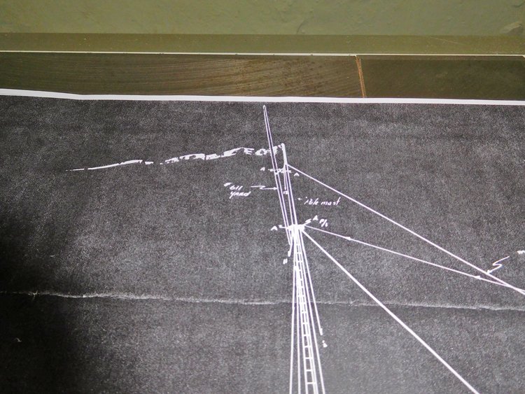
Hello Everyone, I've also posted this question in my build log, but thought I'd place it here as well. I'm restoring an old damaged model of a Virginia Privateer, which I understand to be an example of an American topsail schooner. I have a copy of the original plans and have been able to decipher most of the details, but one bit has me unsure. It's a yard near the top of the main mast and it appears to be mounted in an almost vertical position. It's not something I've come across before and it's unclear to me from the plan how to attach and rig it. I do know that where it's marked "A" it's indicating blocks. There are four shown. The one in the lower right (which actually represents two - p/s) is unrelated, but I'm not sure how to rig the other three, which appear to attach the yard in two places and have two lines which belay somewhere on the deck. If anyone is able to explain, or perhaps illustrate how to do this rigging, I'd be most appreciative. Many thanks, David
-
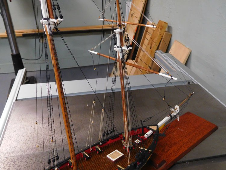
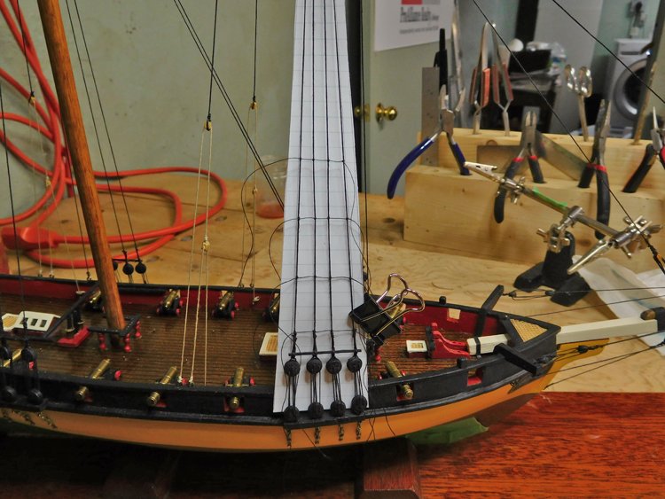
Hello Everyone, A little more rigging progress to report. I've finished the standing rigging and have just started on the ratlines. In an attempt to better control the tendency of the shrouds to pull inward, I'm trying the technique of tying every fourth ratline first. I've also drawn vertical lines on the paper guide where the two outer shrouds lie. It seems to be working quite well. By coincidence, the lined notepaper that I'm using is spaced exactly the same as the plans. The lines are on 6mm intervals, as are the plans. I do have a rigging question that I hope someone can help me with. I'll also post this question under the rigging forum. The plans show a yard at the top of the main mast and I have never run across one just like this before. I assume it's unique to this kind of vessel -American topsail schooner. It's nearly vertical and it's very difficult to decipher from the plan how to attach it and how to rig it. I do know that where the plan indicates "A" that it's referring to a block, but apart from that it's pretty unclear what to do. There are four blocks "A" indicated. I know that the one in the lower right is unrelated (and it's actually a pair - marked "p/s") but the other three appear to be part of the rigging for this yard. Is anybody able to explain or even better illustrate what the setup is? I'd be most appreciative. I think I've figured out most of the other bits, but this one has me stumped. Many thanks. Thanks again, David

- 40 replies
-
- 5
-
-
- virginia
- marine model company
- (and 2 more)
-
And then there's always my way - "measure once, cuss twice." David
-
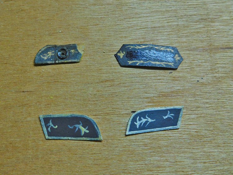
Good Morning Everyone, Thank you for likes and comments. Before starting the standing rigging, the last thing I did was address the trailboards. The port side one was missing altogether and the starboard side was badly damaged. It was painted on cardstock and was delaminating. I was hoping to save it, but it's pretty bad, so I painted two new ones. This kind of painting is not my forte, but I think they're similar to the original, so that will be ok. There is also a similar decoration for the stern, which isn't in bad shape, so I have returned it to its position. The upper left is the damaged original, the upper right is for the stern and the two lower ones on my new ones. There is some kind of grommet on the original, which I have imitated with a blackened brass ring and a hole drilled through into the hull. I then started the rigging. I have the standing rigging on the bowsprit done and am starting in on the foremast standing rigging. You can see my copy of the original plans in the background. The original is a blueprint. When Bill sent it to me, I had a copy made at Staples. I wasn't sure how well it would turn out, but it came very well. These plans are very difficult to decipher, but all the information is there. It just takes a bit of patience and determination to extract it. I'm using black line for the lanyards on the deadeyes for a couple of reasons. The first is, the original had black line and I'm trying to stay as true to it as I can, and the second is because the deadeyes themselves are black and are of very poor quality. I know that many deadeyes are poorly drilled, but these ones are especially bad with very inconsistent placement of the holes. It's almost impossible to get a decent looking job. The black line will minimize the imperfections, whereas a light contrasting colour would emphasize them. That's all for this morning. David
- 40 replies
-
- 4
-
-
- virginia
- marine model company
- (and 2 more)
-
Hi Don, Boy, that stern filler block is an interesting bit. It seems like a good way to get the round profile though. It essentially serves as a form, then when it's served its purpose, you simply carve it out. Looks like it's balsa; I bet you're glad you resisted any urge you might have had to use some old oak that was laying around. David
-
That's looking pretty good Doug. I'm surprised at how finely detailed those gunport hinges are. They're really nice. As for your missing one, I know I'd never manage to successfully cut anything from thin brass. I'd be inclined to make one from card stock, roughly the same thickness as the originals. Considering it's just one, I think it will hold up just fine. David
- 99 replies
-
- 2
-
-
- essex
- cross-section
- (and 1 more)
-
Hi Derek, I'm not familiar with Washi tape, but going by your picture, it looks very much like Tamiya, which is what I use. If it's worked well for you before, then likely as you say it's just a matter of more burnishing once it's applied. Quite by accident I found the ideal burnishing tool. It's a pick from an old set of nut cracker and picks. I thought it might be useful as a pick, but it's too blunt to be of much use, but the back side is somewhat spoon-like and it works beautifully as a burnishing tool. The last time I bought Tamiya tape, the guy at the store asked me if I used the special dispenser for it. The tone of his question implied that I should answer 'yes' if I wanted to retain any degree of credibility, so I said 'yes', even though I don't actually have one. He said that if the tape is laying around it will pick up dirt on its edges and it will affect the outcome. I've never had a problem with this, but I suppose it's possible. Did you see the post today by Nic from Blue Jacket? He was dealing with the same problem as you on the hull of a model he's working on. David
-
Hi Derek, What kind of tape are you using? David