


davyboy
-
Posts
714 -
Joined
-
Last visited
Reputation Activity
-
 davyboy reacted to michael mott in Young America 1853 by EdT - FINISHED - extreme clipper
You Know Ed I can see Longridge coming over to your place and saying "right I wish I had done that".
Wonderful work simply wonderful work.
Michael
-
davyboy reacted to KeithAug in Home Made Mini Mill
So here goes with a little more progress.
The bearing houses stands off the sliding plate by 2 inches. A 2"x2"x1" piece of aluminium was cut from bar and the ends machined square.
The bearing housing is drilled and tapped (M8) to take the bolts that will secure it and the stand off to the sliding plate.
In the previous photo the bearing housing is held against the mill table by the black clamp while the side clamping is achieved through the bar with 5 horizontal cap bolts. I made this some time back and find it very useful.
A recess is cut in the bearing housing to take the stand off. The set up means that the recess is parallel with the axis of the housing. The fit of the stand off into the housing has to be good to make sure that the housing axis is parallel with the stand off.
The quality of the fit is illustrated in the next photo where the housing is suspended from the stand off by friction alone.
A better view of the joint can be seen in the next photo.
I needed bearing retaining plates for either end of the bearing housing, these were cut from 0.1" aluminium plate.
The next step was to create the cut out and holes for attaching the stand off to the sliding plate.
This was virtually a repeat of the operations to connect the stand off to the bearing housing.
And once again I did the friction suspension test to demonstrate the fit.
The next photo shows all 3 parts assembled and held together by friction.
Thats it for the present. Tomorrow I am going to have a go at machining up the spindle and mounting it in the bearing housing.
-
 davyboy got a reaction from mtaylor in HMS Tiger 1747 by Siggi52 - 1:48 - 60 gun ship from NMM plans
Hi Siggi,
I have 2 photographs of a contemporary model of the 60 gun ship HMS Achilles of 1757. I took these in the Science Museum in London 11 years ago,there are no Fish or Horseshoe plates shown on this model. It postdates HMS Tiger by a decade so it may be ok to assume they were not fitted on your ship. However,it could be that they were just omitted on this HMS Achilles model,who knows. Yet,all other hull fittings are shown as fitted. Hope this is of help to you. Perhaps one of the very knowledgeable forum members hopefully may be able to answer your question.
Kind regards,
Dave
-
 davyboy got a reaction from Siggi52 in HMS Tiger 1747 by Siggi52 - 1:48 - 60 gun ship from NMM plans
Hi Siggi,
I have 2 photographs of a contemporary model of the 60 gun ship HMS Achilles of 1757. I took these in the Science Museum in London 11 years ago,there are no Fish or Horseshoe plates shown on this model. It postdates HMS Tiger by a decade so it may be ok to assume they were not fitted on your ship. However,it could be that they were just omitted on this HMS Achilles model,who knows. Yet,all other hull fittings are shown as fitted. Hope this is of help to you. Perhaps one of the very knowledgeable forum members hopefully may be able to answer your question.
Kind regards,
Dave
-
davyboy reacted to Louie da fly in Venetian Carrack or Cocha by woodrat - FINISHED - 1/64
SUCH a beautiful ship. I particularly like the final photo in the series, juxtaposed with the original drawing which you used as your main model in building her. And the quality (and quantity) of research has, in my opinion, resulted in a model as close as humanly possible to what actually sailed the seas. Not to mention the brilliant workmanship.
You have good reason to be proud of this model, Dick. I look forward to the next build.
Steven
-
davyboy reacted to EdT in Young America 1853 by EdT - FINISHED - extreme clipper
Young America - extreme clipper 1853
Part 281 – Main Yard Rigging 2
The first picture shows the main yard ready for the next rigging steps. The taut chain sling may be seen in this picture.
The topsail sheet chains are hanging from the cloverleaf sheet block under the center of the yard. As described before, these chains are linked over the central pin within the block to allow them to pull down on the yard using the two tackles soon to be added. This also permits the chains to hang somewhat slack under the yard on their way to the cheek blocks at the ends. The two triple tackles for the sheets are shown rigged in the next picture.
The lower blocks of these tackles are hooked to deck eyebolts just forward of the mast and the falls are belayed on the topsail sheet bits using the long horizontal belaying pins. The next items to be installed are the clue garnets with the main sheet blocks, tacks and lazy tacks attached to a single large shackle. The next picture shows the prefabricated gear for one side.
The large line is the tack that was used to haul the weather side of the sail taut. The smaller line is the lazy tack, used to control the sail as it was switched from tacks to sheets while the yard was being braced when the ship tacked. The large block is the sheet block. The sheet will be added later. At this stage outboard rigging – mainly braces and lower course sheets – would be an obstacle to the work and subject to damage. The smaller attached block is for the clue garnet. The standing end of that line is shackled under the yard, passes through this block, back through one sheave of the quarter block and belays on the main fife rail. The hooked double block in the picture is a quarter block. The second sheave on this block takes the fall of the reef tackle. The next picture shows these lines rigged.
The tacks are belayed on cleats on the bulwark rails and the lazy tacks to the first pins on the main pin rails. These remain unglued so they may be adjusted when the sheets are added later. In the next picture the topping lifts, buntlines, leechlines and reef tackle have been added.
The next picture shows a closer view of these lines.
The bunt and leech lines pass through single blocks hooked under the rim of the top, down through shroud fairleads and belay on the main pin rails. The reef tackle falls pass under the yard, through the aft sheaves on the double quarter blocks, and belay on the fife rail below next to the clue garnets. Next the bowlines.
Ed
-
davyboy reacted to Mirabell61 in Two miniature moliceiros by Javier Baron - scale 1:110 - Finished
Wow ! Javier,
what a detail in paint work, it looks outstanding !
Nils
-
davyboy reacted to Javier Baron in Two miniature moliceiros by Javier Baron - scale 1:110 - Finished
Thanks, Nils.
The first of the two Moliceiros is already painted. In my case the “paineis” do not carry a legend, because I have to admit that I am unable to write on that scale, so I have tried to simulate the "shadows" of a text, whose content I leave to the imagination of the observer .
-
davyboy reacted to Ondras71 in Roter Löwe 1597 by Ondras71
Thank you Michael Mott. I started measuring and painting lines for placing the pins .. Before drilling, I decided to use a spike to get the accurate spacing of the holes.. -
davyboy reacted to Ondras71 in Roter Löwe 1597 by Ondras71
The left part of the hull is finished and ground before installing the pins..
-
davyboy reacted to Ondras71 in Roter Löwe 1597 by Ondras71
Thank you very much Backer, Ferit KUTLU..
The planking continues, difficult places at the stern under the mirror already done.. Bow closed and ready to install pins ..
-
davyboy reacted to DORIS in HMS ROYAL KATHERINE 1664 by Doris - 1/55 - CARD
Current status
Have a great time and enjoy the pics.
-
davyboy reacted to Siggi52 in HMS Tiger 1747 by Siggi52 - 1:48 - 60 gun ship from NMM plans
Hello again,
and thank you for your likes and comments.
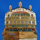
Hubac, now and then you see it in this forum. Also my Dragon has these staples.
After sanding the whole forenoon, I think the lower hull is ready now. I should have started with the first drop plank at the 1. diminishing strake. But later you are always smarter
The next thing to do is, I think the ruder. Then I know how large the opening in the lower counter must really be.
But because here the spring came from one day to the other, I think my garden needs my attention first. The week before Easter we had two snowstorms with each 10 cm snow here. More north they had over 50 cm! One of my oaks lost a big branch then, and the experts will come Friday to cut it out. But also for me is enow left.
-
 davyboy got a reaction from PeteB in La Jacinthe 1825 by aviaamator - 1:20 - schooner
I do believe the comment was just a poor joke,observe the winking smiley. Aviaamator,your workmanship is superb.
Dave
-
davyboy reacted to Charter33 in Ropewalk (and serving machine)
Hi,
Last October a thread started by Derek (Worldway) in this section of the forum gave me the final nudge to get started on making my own ropewalk.
I have previously built a serving machine and decided to try and use similar construction techniques such as using acrylic for the main structure and modified Lego gears for the mechanism.
Here are some pictures of this earlier project:
The Ropewalk:
Clear acrylic components were built up to make wheels and pulleys. Small holes around the rims aid alignment using the brass pins recovered from the first planking on my HMS Victory - I knew there would be a reason to keep them!
The Lego gears had their centers machined out and replaced by acrylic hubs. These have a square hole in the center through which 5/32" square brass tube is pushed. This tube, after a little filing, slides firmly into 6mm O/D brass tube axles which in turn fit into the ball races press fitted into the various support plates.
The track is in sections each about a meter long, which slot together.
I decided to try and use one motor to drive the end that twists the individual strands and a second one to twist these strands together.
The control box provides separate on/off switches, variable speed control and finally a switch to reverse the direction of rotation.
The motors were initially powered by batteries but I have now replaced these with a 6 volt power supply.
The 'Top' which guides the strands is mounted on an acrylic truck. This is fitted with the three stand top in the photo but there is also a four stand top.
These four strand gear plates are easily fitted in place of the three strand gear drive.
In use the strand twisting end is fixed to the track but the other end that twists these together to produce the final rope is free to slide along the track as the twisting process reduces the length of the rope. I'm still getting to grips with the best way to operate this device and need to experiment more with types of yarn, motor speeds etc. Early attempts are encouraging however..........
Cheers,
Graham.
-
davyboy reacted to Mike Dowling in Fokker Dr.I by Mike Dowling - FINISHED - Artesania Latina
Upper wing ready to go on.
-
davyboy reacted to KeithAug in Home Made Mini Mill
Michael, Druxey, Aviaamator, thank you for looking in and for your supportive comments re my recycling efforts. More to follow:-
I finished refurbishing the lead screw, reassembled it and mounted it in the column.
I had been giving some thought to the design of the milling head and in particular the type and arrangement of the bearings. Anyway the other night I was lying awake mulling it over when I remembered that I had a broken router in the garage. The router was little used in its first year - probably less than a couple of hours. Early in its second year it developed a winding fault and wouldn't self start. Its was just out of warranty and the cost of repair was nigh on the same as replacing it - so a replacement was bought and it found its way into the rainy day store. The speed and power rating was well in excess of my mini mill requirements and I thought the shaft, bearings and collet chuck would suit my purposes rather well.
Stripping down was relatively straightforward and soon the rotor and bearings were out.
Removing the rotor winding wasn't easy at all but it was eventual "hacked" off after an hour of sawing.
I did a redesign of the milling head after looking at the arrangement of a couple of commercially available mills.
I decided to make the bearing housing out of a 2"x2"X3.5" square aluminium bar. I ordered a piece for the purpose - 8 inch long and £13 from fleabay.
Chopping off the required length was another hacksaw marathon.
The cantilever stem supporting the bearing housing was cut from 2" X 1" aluminium bar from my metal stock. Both items were faced off square using a fly cutter. I love flycutting its so satisfying to see the almost mirror finish appear.
Its going to fit together something like this:-
There trick to making this work is to machine the bearing housing accurately - so that the shaft runs true. I took a lot of care when mounting the bearing housing in the mill. As bought the bar had a good surface finish and was square and parallel. I used a .0005" graduation dial gauge to check verticality on two adjacent faces. A lot of tapping with a hammer and checking and rechecking using the dial indicator finally got both vertical faces to within .0005" over the 3.5 inch length.
I drilled through the 3.5" length of the bar to take the shaft. A bit of a heavy job for my mill which complained quite a lot. This operation wasn't helped by my smaller twist drills being somewhat shorter than the hole being drilled. However eventually I got through.
I then had the job of opening out the ends to take the bearings. The bearings needed to be a very good fit so I took it real slow using my boring head - that is the head in the picture and not the head on my shoulders.
Having done one end I flipped the bearing housing over and went through the whole laborious process with the dial gauge once again. This time it took even longer - probably about an hour (although my wife tells me time is distorted in the black hole of my workshop). Each end has 4 holes which will take a plate that clamps on to the outer race of the bearings.
I managed to get the bearings nicely fitted with no slop.
I need to give a bit more thought to the arrangement of the belt drive - maybe in the early hours of tonight.
-
davyboy reacted to Baker in Golden Hind (ex-Pelican) by Baker - FINISHED - scale 1/45 - Galleon late 16th century
The door is more detailed.
Windows are made of clear plastic (PVC). And it is the intention to become glass in lead.
First i make grooves with a needle in the plastic.
Then the "lead" insert is made with stretched sprue (light gray sprue has been used and is not painted)
the clear plastic and wood fittings are glued and colored.
ready
Thanks for following
-
-
davyboy got a reaction from mtaylor in La Jacinthe 1825 by aviaamator - 1:20 - schooner
I do believe the comment was just a poor joke,observe the winking smiley. Aviaamator,your workmanship is superb.
Dave
-
davyboy reacted to Angarfather in Golden Hind ex Pelican by Angarfather - 1:36
Aye, Mates!
Many thanks for your kind words and all the likes.
The last weeks was not so much time for modelling the Golden Hind. There had been many interesting job. Thats ok. Here are some pics from the last days.
To finsh the wales in the bow I first did mount the upper and the lower wale. After this I use spacer blocks to mount the bow part of the wale in the middle
The last wale piece
Next step was planking the space between the two lower wales and the stern.
Cheers! Hartmut
-
davyboy reacted to Erebus and Terror in HMS Terror by Erebus and Terror - FINISHED - Scale 1:48 - POB - as fitted for polar service in 1845
A small update, folks. Negotiations with OcCre have progressed nicely and we have resolved the issue to my satisfaction. As soon as all the paper is signed I'll announce it on the forums. I was impressed by their handling of the issue; they take intellectual property and copyright pretty seriously. Thanks for all the support and advice from everyone here!
-
davyboy reacted to druxey in HMS Terror by Erebus and Terror - FINISHED - Scale 1:48 - POB - as fitted for polar service in 1845
Excellent news, E&T! Too bad they did not establish authorship before they went ahead. Hopefully, they will on another occasion.
-
davyboy reacted to Blue Ensign in HM Cutter Cheerful 1806 by Blue Ensign - FINISHED - Syren Ship Model Company - 1:48 scale
Cheers Guys,
Post 24
The first planking Belt - Preparation
I intend to follow Chuck's methods as closely as I can from this point on.
So it's tick strips and pinstripe tape to try and get somewhere, anywhere, close to Chuck's example.
Eight additional 3/16" wide strips required for this first belt at the centre.
Simple enough to determine the limit of the eight strakes below those already fitted at the centre bulkhead using the tick strip.
7782
The stern position at the square tuck is easy to see.
7784
Counting down on the plan the first belt seems to terminate around the stem scarph joint at the bow.
7780
A tricky business getting the tape on, bally stuff was very reluctant to stay put and getting a nice run of tape along the hull took some time.
7777
Hopefully I've got it right.
7786
With the reference stations marked it's onto the tedious business of making up the tick strips for the rest of the bulkheads.
7789
For this job Cheerful is transferred to its low support base, easier on the arms and the eyes.
B.E.
11/04/2018
-
davyboy reacted to Javier Baron in Two miniature moliceiros by Javier Baron - scale 1:110 - Finished
I have manufactured the two rudders, and in the following photos, in which I show them each presented in their respective vessel, it is possible to clearly appreciate the differences that, following in each case the corresponding plane, exist between both moliceiros. Not only the rudder has a different profile, but also the height of the rail and the curvature of the bow.
The forested benches and the cockpits are already assembled. I have also added the doors of the “camaretas”, the moldings that in the “vertente” or “bar” support the “mastaréu”, and the holes to fit it in the corresponding frame.