ccoyle
-
Posts
9,939 -
Joined
-
Last visited
Content Type
Profiles
Forums
Gallery
Events
Everything posted by ccoyle
-
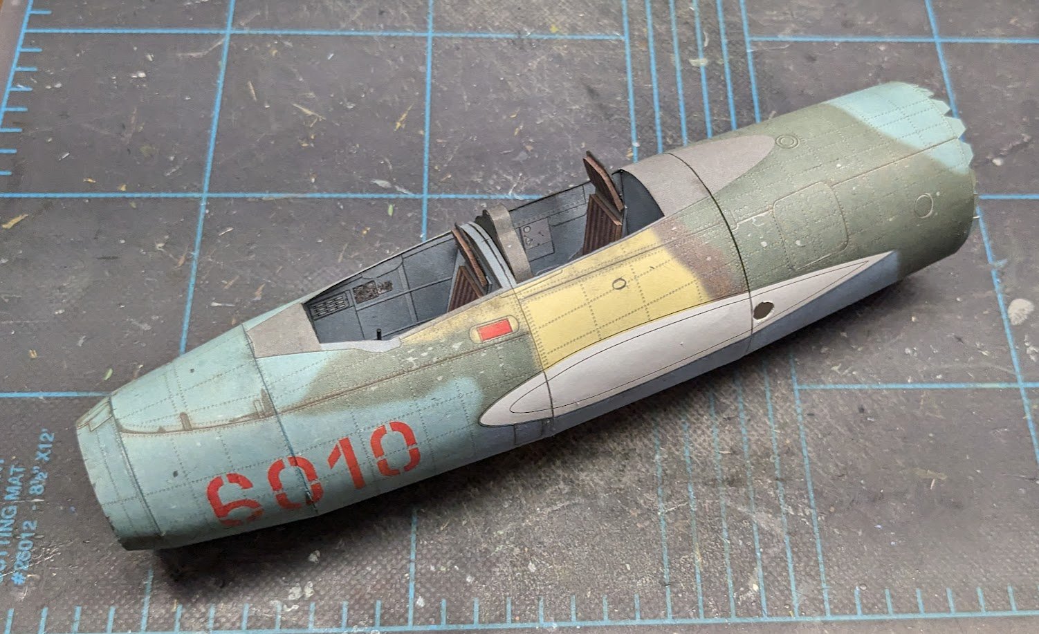
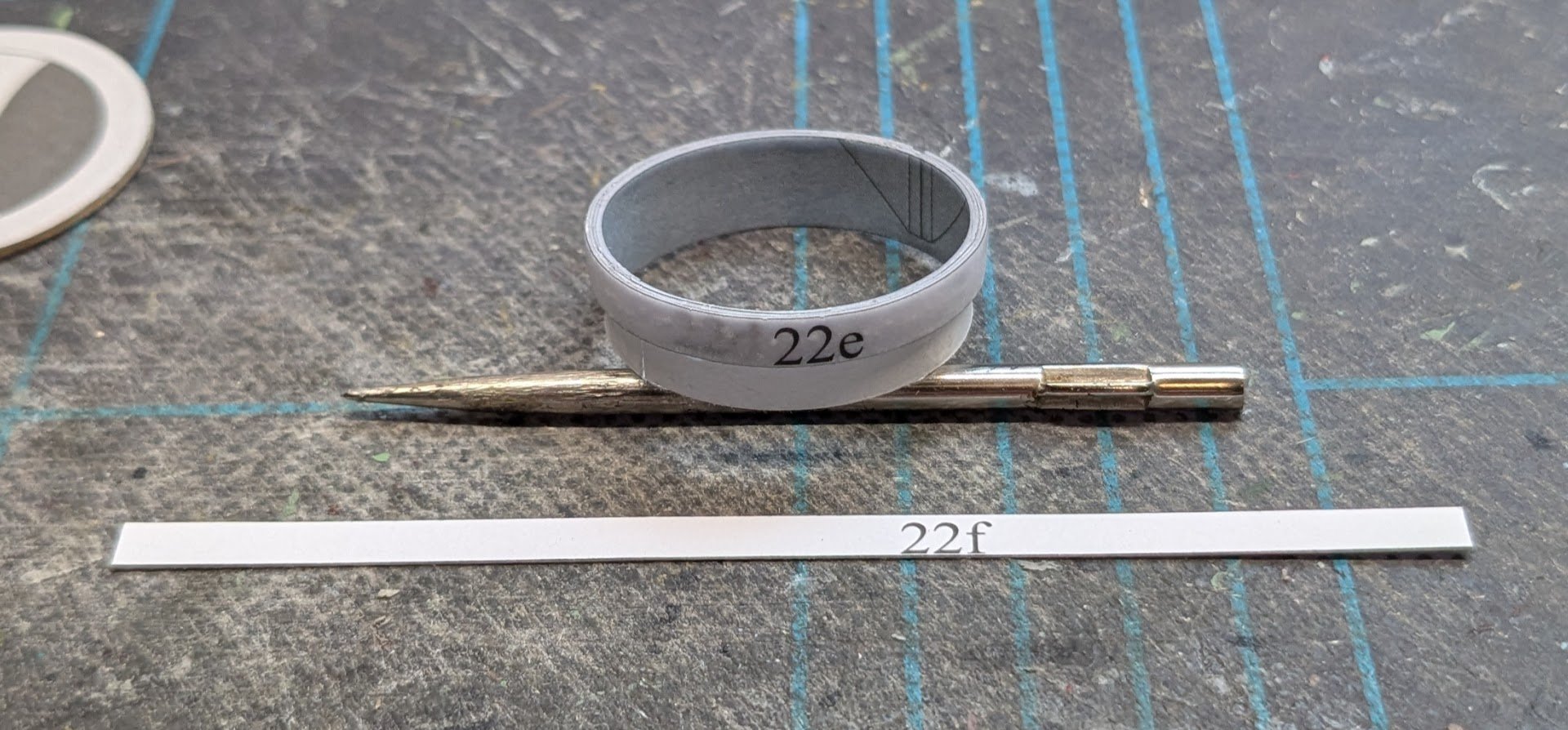
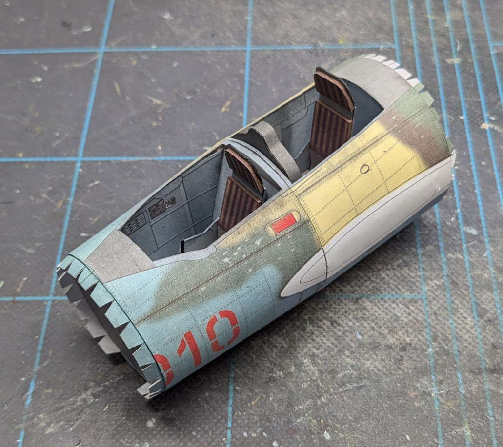
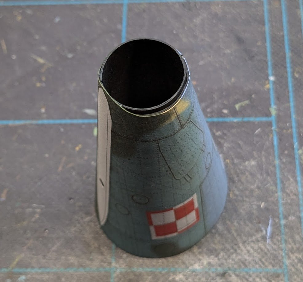
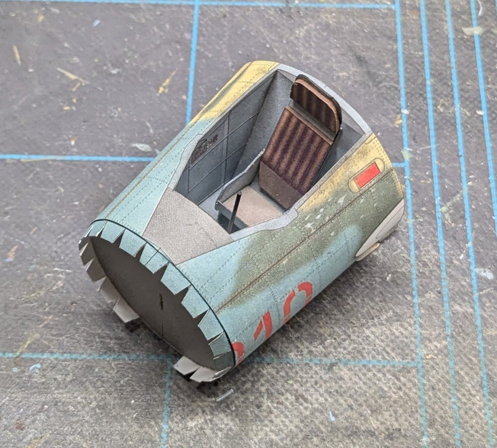
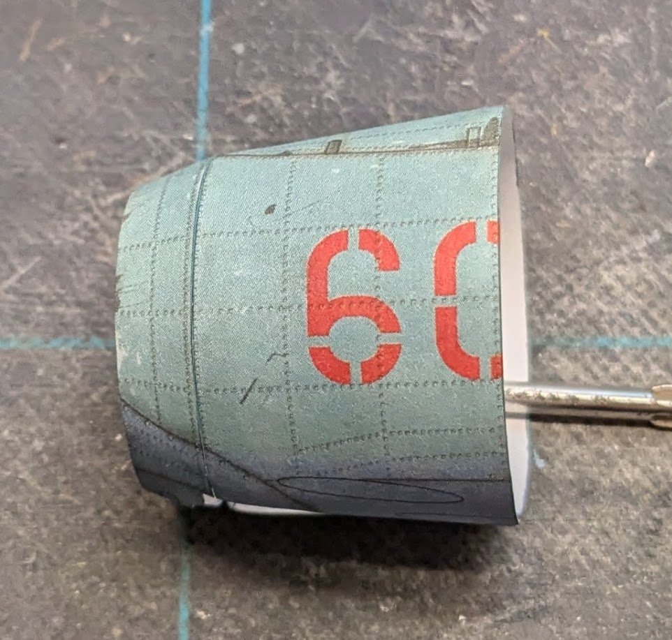
 Now for the last fuselage section. It begins with the engine exhaust nozzle, a rudimentary structure consisting of four concentric rings and a bulkhead. Warning: the inner nozzle piece was too long and ended up forming a cylinder with a diameter too large to wrap the outer piece around. I fixed this by forming the outer cylinder first, adding the bulkhead, and then trimming the inner cylinder to fit inside. This finished basic cylinder gets wrapped with a pair of spacers. The last fuselage section is a simple conic section with a joiner strip. After that is glued and has had time to dry, the faux exhaust nozzle is added from the front and the spacers (not the cylinder!) are aligned with the end of the cone. Yet more drying time, after which we can glue the last section to the rest of the fuselage. With that, the fuselage (except for the canopy and gun sight) is done! Next we'll move on to the empennage.
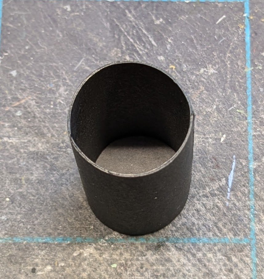
- 66 replies
-
- 12
-

-

-
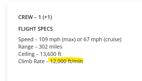
According to this website, the last Tiger Moth landing on a carrier was in 1967, and Tiger Moths were in service until the early 70s. Of course, that same website claims the Tiger Moth had a 12,000 ft/min climb rate -- whoa!! 😮
-
Great! Now I can say my life has overlapped the era of biplane carrier operations. 😂
-
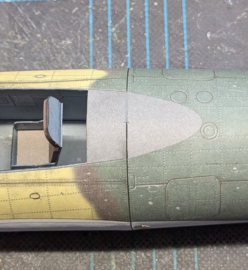
No, the treatment is an idea that popped into my head while pondering the fact that the seams appear much darker than the surrounding print (but I'm sure I'm not the first person who ever thought of this). I created a thin wash from very dilute white glue and light gray paint. The hope was that the wash would tone down the edge coloring without completely covering it -- kind of like looking out a window covered by gauzy curtains. The wash is thin enough to wick into the offending seams.
-
Hi, Andrew. Just today I saw a finished example of this very kit on the "I love scale models" FB group. If that build was any indication, this kit should yield a fine end product.
-
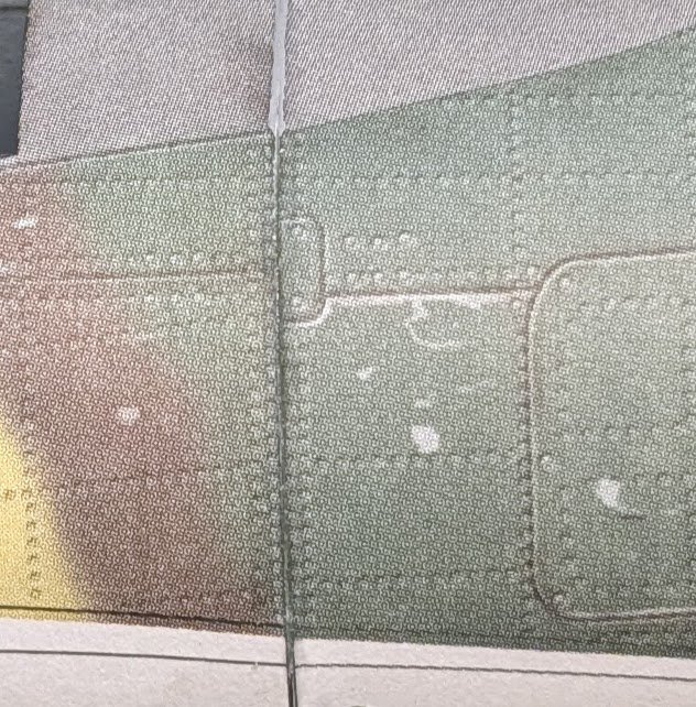
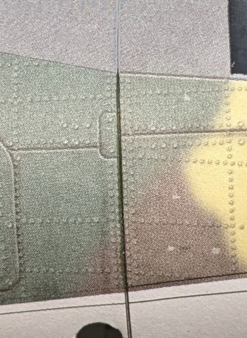
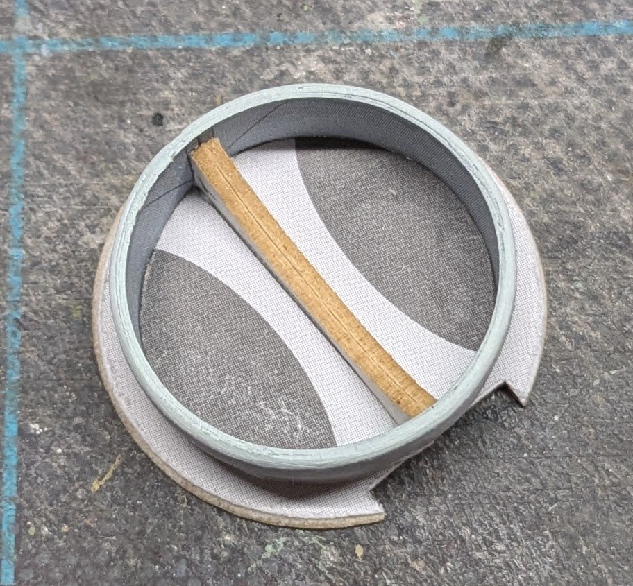
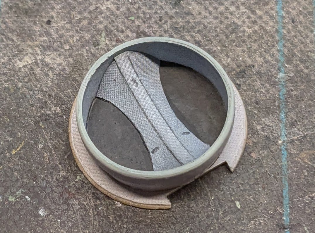
I'm experimenting with trying to hide seams, or at least tone them down. Treated (top) vs. untreated (bottom). Treated (left) vs. untreated (right).
- 66 replies
-
- 14
-
-
Would that happen to be one of the Polish forums? I check the gallery at Kartonowki often, but since I can't read Polish (except for very basic modeling terms like drut or klej ), I don't visit the others regularly unless I am looking for builds of a specific kit.
-
Your paint job turned out nicely.
-
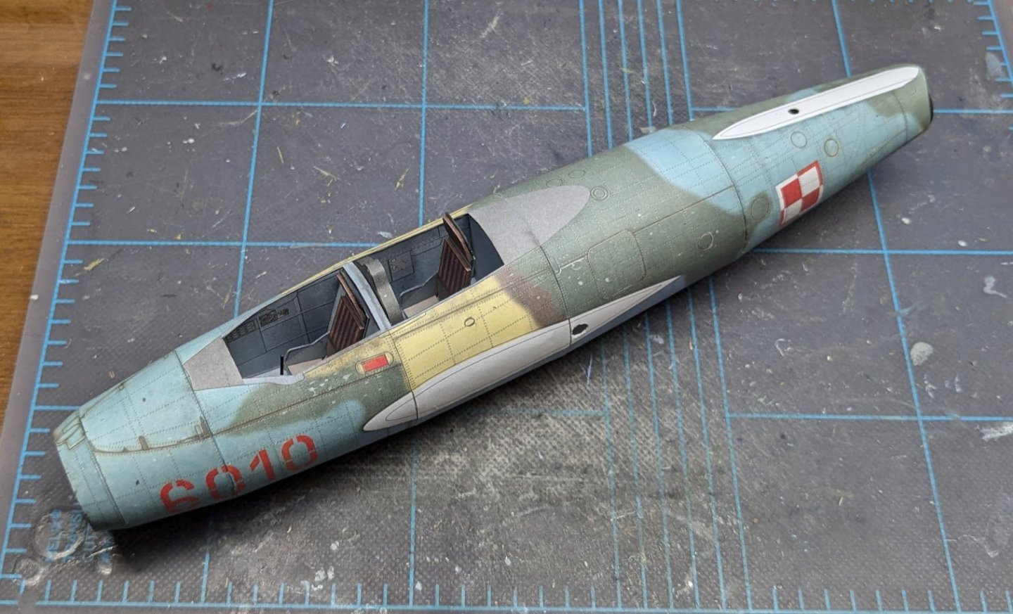
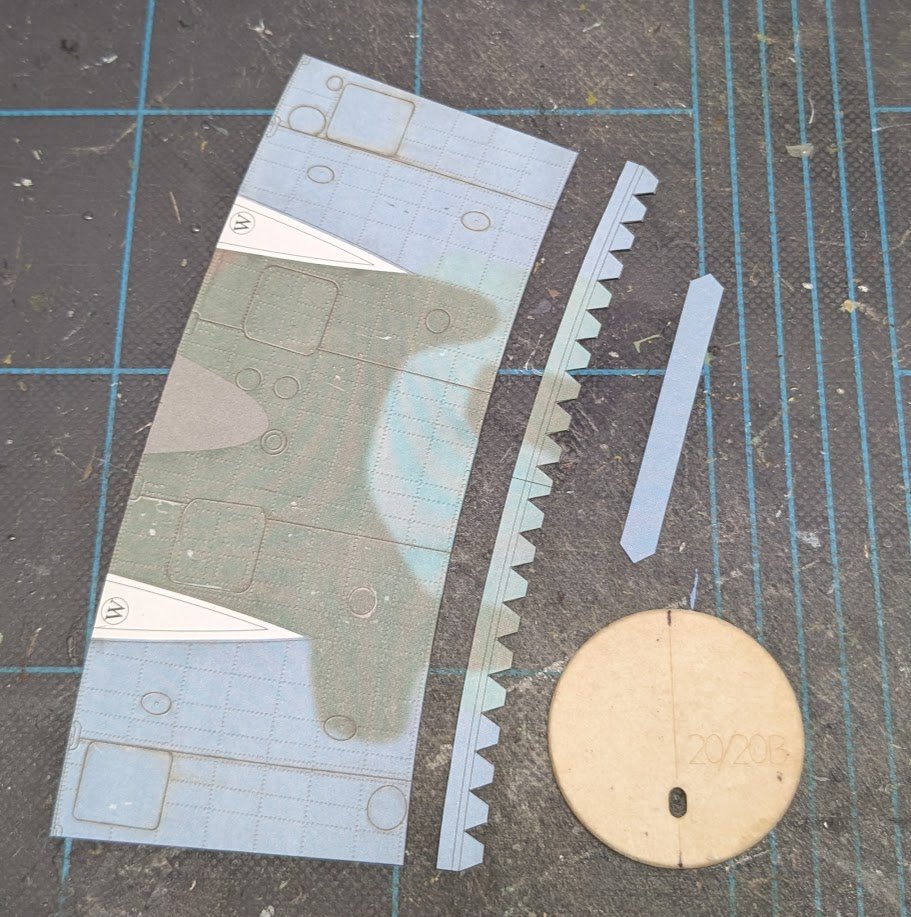
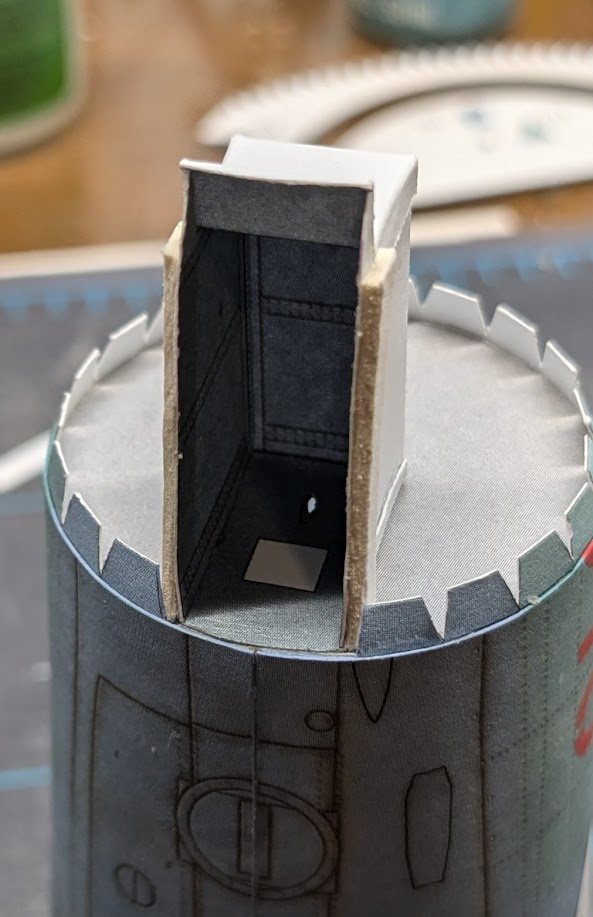
Time to work on the aft fuselage. This next fuselage section was supposed to be added before working on the nose section according to the instructions, but that fact was only very briefly mentioned, which is how I managed to overlook it. In reality, it makes no practical difference whether one adds it earlier or only just now, as I have done. This section is a basic ring structure plus a bulkhead. There are two spots, marked with a 'W', that must be cut out. You can do that now, or after the section has been added to the fuselage. The latter option is advisable, since cutting them out now will create two weak spots along that edge. And here's the fuselage after that section has been added. Just one more section to go!

- 66 replies
-
- 13
-
-
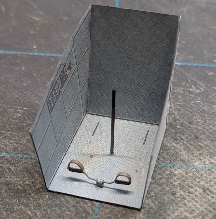
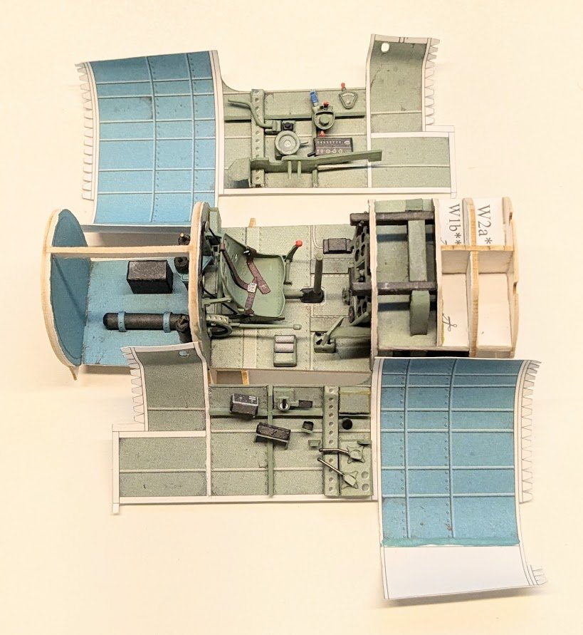
BTW, just thought that some might appreciate seeing the difference between an intermediate-level cockpit and a Halinski cockpit. 😂
- 66 replies
-
- 13
-
-

-
Very nice!
-
Congratulations on a very sharp result!
- 61 replies
-
- 1
-
-
- prince de neufchatel
- model shipways
- (and 1 more)
-
how to value a pre 1950 model of the Santa Maria
ccoyle replied to amuzed_traveler's topic in New member Introductions
Since we don't really have a dedicated discussion area for topics like this one, I have moved it to the member introductions area. -
Parts an parts # building the norske love 1:75
ccoyle replied to joebgame's topic in Wood ship model kits
Since the question concerns a specific kit, I have moved the topic to the kits discussion area. Can't help you with the numbering, though. 😬 -
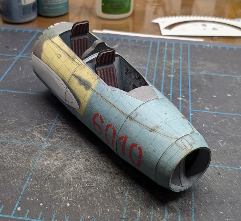
Okay, I made a significant blunder in this next phase! 😬 More on that in a moment . . . Next we assemble the air intake duct. A pair of laser-cut parts form the divider. You can see that I somehow managed to scuff the black portion on the left side, so I painted over both faux recesses. The left side of the sheathing needed very slight trimming, as did the center-line covering strip. There are two ways you can do the forward section with the intake, either add the intake to its smaller ring and then join the two rings together, or glue the rings together first and then add the intake. I strongly advise the latter option. There is no joiner strip provided for the forward ring, so I mad a small one from 20# bond. Joining the rings might seem awkward at first because the aft ring isn't closed at this point, but the task is not difficult. Next I added the wheel well to the cockpit section. There is no tic mark printed on its interior, but you can easily position the well by aligning its hole (where the nose wheel strut will go later) with the hole in the bulkhead and its sides with the fuselage's printed lines. And here's the finished nose. When joining these two sections of fuselage, care must be taken to make sure the forward projection of the wheel well fits into the bulkhead gap provided for it and within the fuselage skin. Don't forget to add glue to the wheel well sides where the ends of the fuselage ring land on them. Let's see -- did I forget anything? Oh, yes, that's right -- I forgot to add EXTRA WEIGHT to the interior of the nose! 😑 Derp!! Oh, well -- I have a solution in mind for that when the time comes. That's it for now!
- 66 replies
-
- 13
-
-
Welcome aboard, friend. Pleasant stay be yours, enjoy! Haiku I write poor.
-
Such an iconic aircraft! And of course the surviving examples around the world wear a wonderful variety of liveries.
-
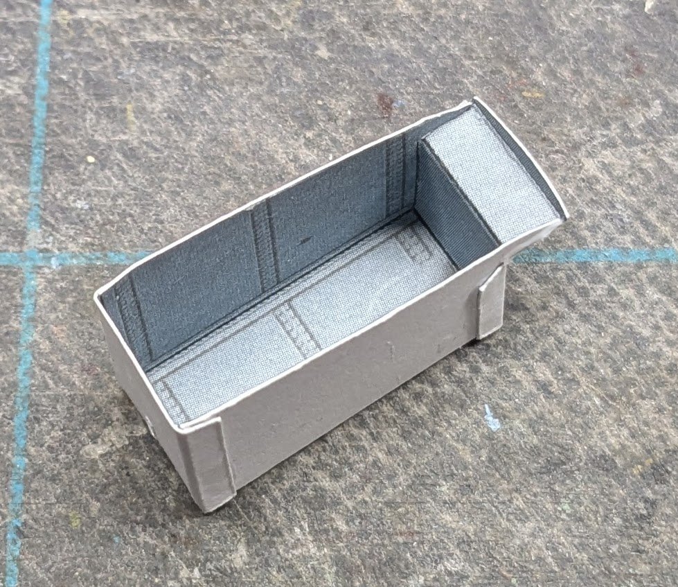
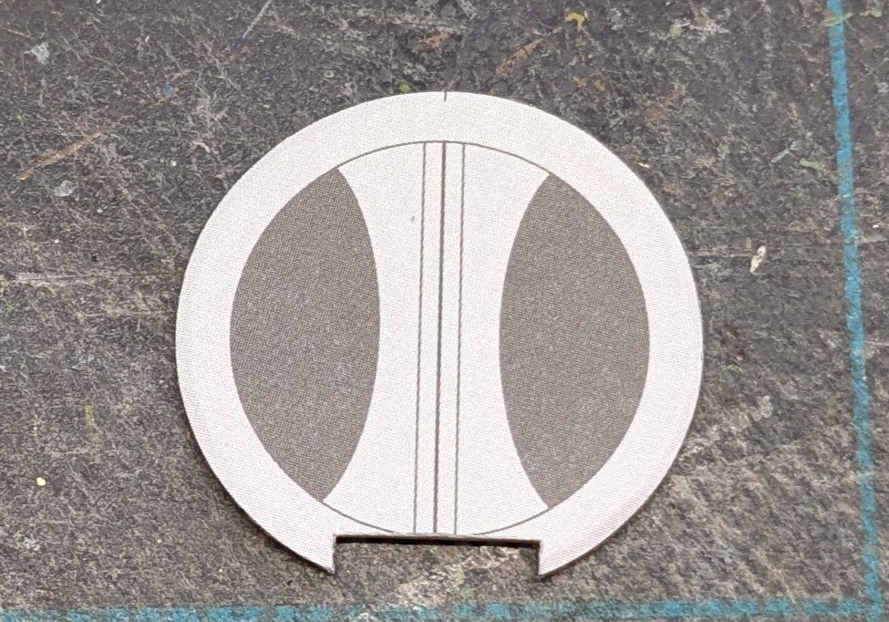
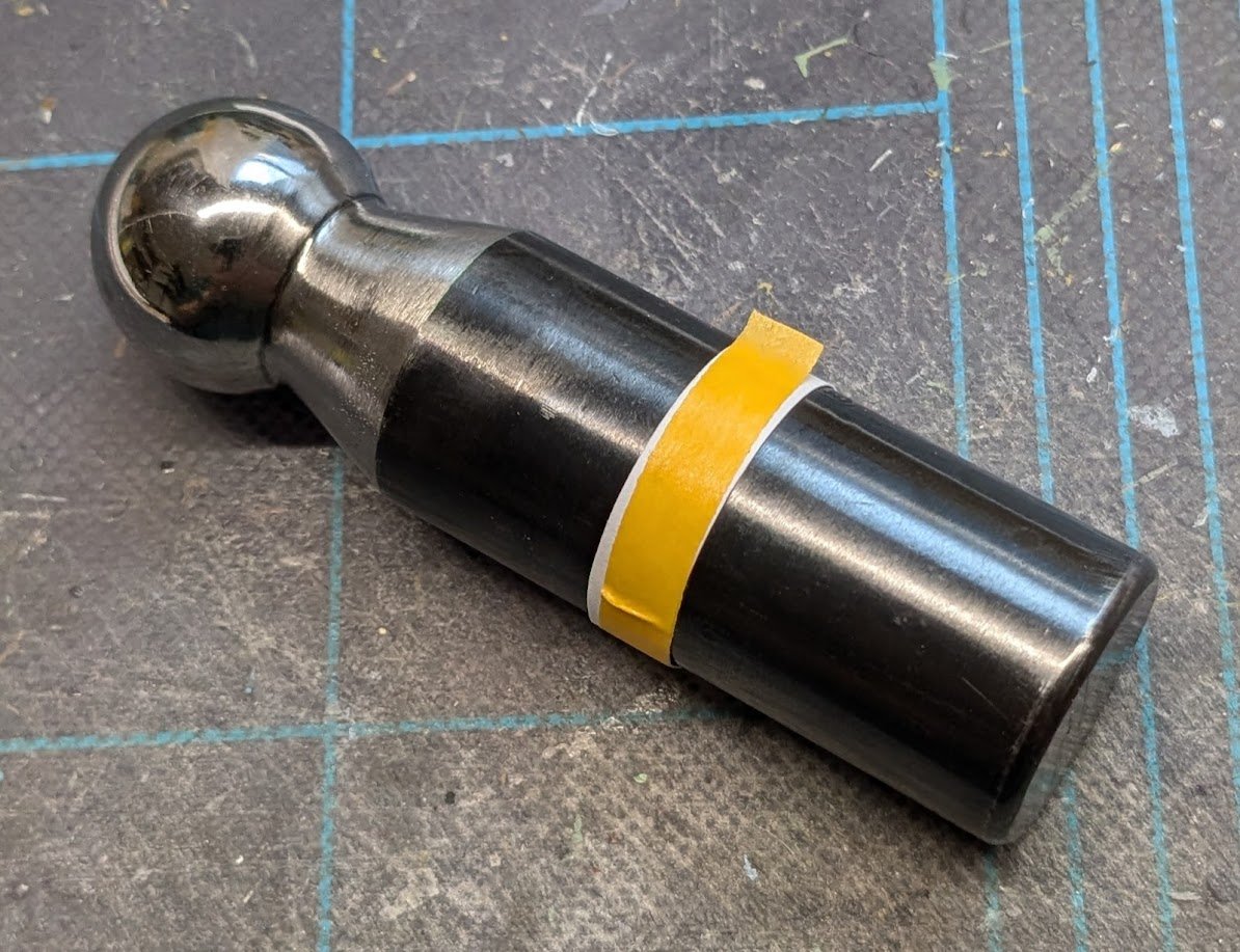
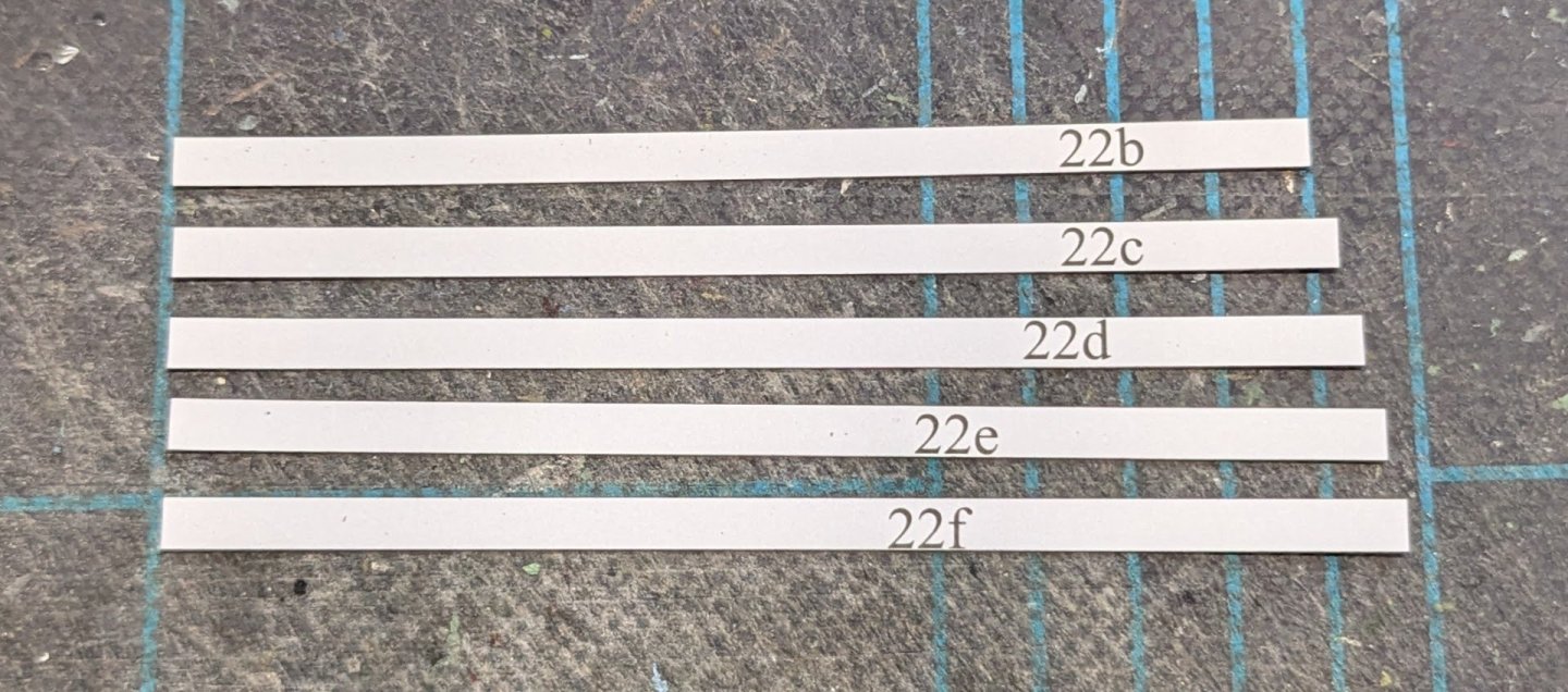
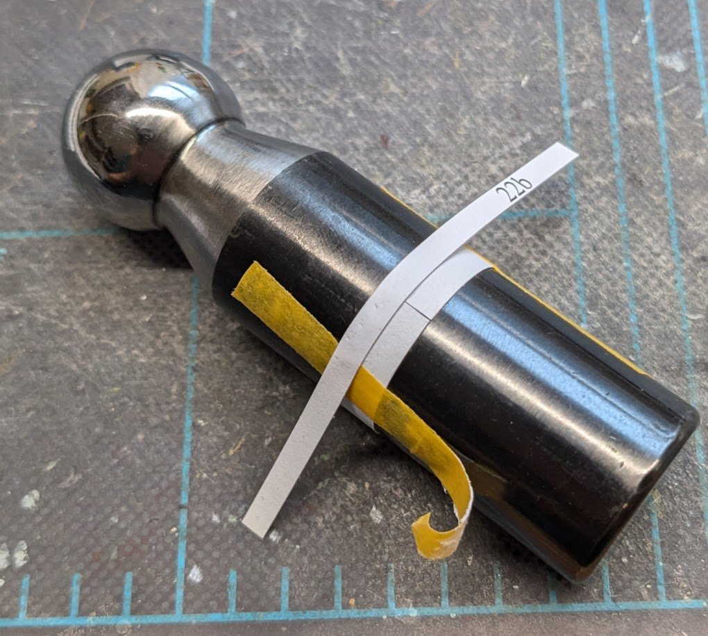
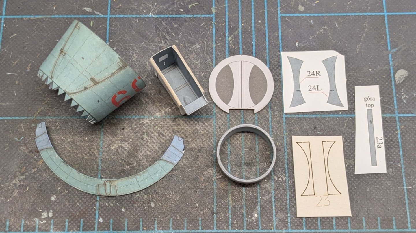
Now we get into one of the construction sequences that is affected by whether the builder opts for wheel wells. If you choose to omit wheel wells, the sequence is pretty straightforward -- just two more conic sections and a bulkhead. (NOTE: Regardless of option, weight must be added to the interior of the nose for the model to sit correctly on its tricycle gear.) If you decide to go for the wheel wells, well then things get a little dicier. First we fold and glue up the nose wheel well -- no biggie. I later added scrap card strips along its sides, as I did for the observer's tub. DO NOT add strips to the front or back -- the tub is designed to fit snugly between two bulkheads. Note that there is a small projection on the forward end of the well. Here we have the forward bulkhead with the faux air inlet laminated to it. The builder can either leave it like this or choose to add a more detailed inlet divider. The cutout at the bottom is only done for the wheel well option -- this is where the previously mentioned wheel well projection passes through the bulkhead. The next part could be a challenge. The first part of the detailed air inlet consists of a printed interior color ring that has to be wrapped in multiple paper rings. The challenge lies in getting the first ring perfectly round. Here's how I went about that. First, I needed to pre-shape the interior color ring. Happily, it fits perfectly around the handle of a 23mm dapping tool. The part was dampened, wrapped, taped, and allowed to dry. Note that the color side goes on the inside of the ring. Note that the ring parts are lettered b to f and that their lengths increase slightly with each part, because as each one is added, the diameter of the ring increases. Leaving the first ring on the dapping tool, I overlapped the seam with ring b to close the first ring. For each successive ring, I shifted the seam slightly so as not to create a weak point in the ring's structure. Here's the finished ring with some items to note. First, I wrapped the wrong end of the interior color cylinder. 😑 The wrapped rings should be at the front of the cylinder, and the little printed triangle on the interior ring points in that direction, hence my rings are on the back. Fortunately, this is only a minor error, but it's still annoying. Second, I did not add ring f; I noticed that each ring produced a widening gap at its seam, indicating some error creep, so on the very strong suspicion that the ring will be slightly too large even at this stage, I chose to leave the last ring off. Lastly, I soaked the outside of the ring with CA to stiffen the part. Finally, here's a group shot of all the parts that will go into making the nose of the aircraft: two conic sections, the wheel well, the inlet bulkhead, the inlet ring, and the parts to make the inlet divider. Unlike the previous fuselage sections, the larger ring here has no seam tab, since its two ends will land on the wheel well (hence the addition of the scrap card along the well's sides), and the smaller ring does not wrap around a bulkhead -- it will be glued to the joiner strip on the larger ring aft and to the interior air inlet ring forward. I suspect I may need to bevel the inlet ring to get things to fit easily. Fingers crossed!

- 66 replies
-
- 12
-
-
My folks had a '55 Chevy. Sold it before I was old enough to drive it. 😢
-
Nice to hear the voice that goes with the models! It was fun hearing your hosts describe one or the other of your models and thinking, "Hey, I've seen that one!"
- 76 replies
-
- 2
-

-
-
- Micromaster
- Eduard
- (and 4 more)