HOLIDAY DONATION DRIVE - SUPPORT MSW - DO YOUR PART TO KEEP THIS GREAT FORUM GOING! (Only 27 donations so far out of 49,000 members - C'mon guys!)
×


toms10
-
Posts
929 -
Joined
-
Last visited
Content Type
Profiles
Forums
Gallery
Events
Everything posted by toms10
-
 Thanks for compliment. It means a lot coming from a master such as yourself. By the way, you are right, I do have old hands. PeteB, Glad to have you on board. Again thanks for the kind words. Solidworks is what I use for work (mfg design engineer). The program or pretty much any drafting program, 2d or 3d should be able to generate the prints for the frames. I only draw enough of the parts I need to continue. The rest is made up as I go along. I have no intention of producing a full 3d model of my model. Tom
 -
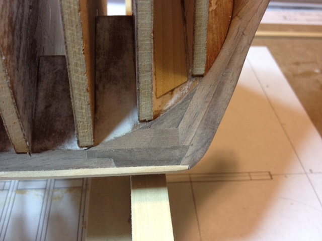
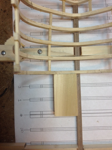
Got just a little bit further. Finished gluing the rest of the frames and bulkheads. Also finished the false keel and keelson. Here is a close up of the bow area. I decided make the bow stem from individual pieces instead of one solid piece of walnut. Tom
- 385 replies
-
- 12
-

-
I did hear a rumor that there are only 2 people left in the world that do not know where Wolcott is located. It is between Waterbury and Bristol. Now there is only one left... hmmmm.
-
Hi Bill, I am in Wolcott. I am sure you have heard of it. It is a major metropolis of universal importance. Tom
-
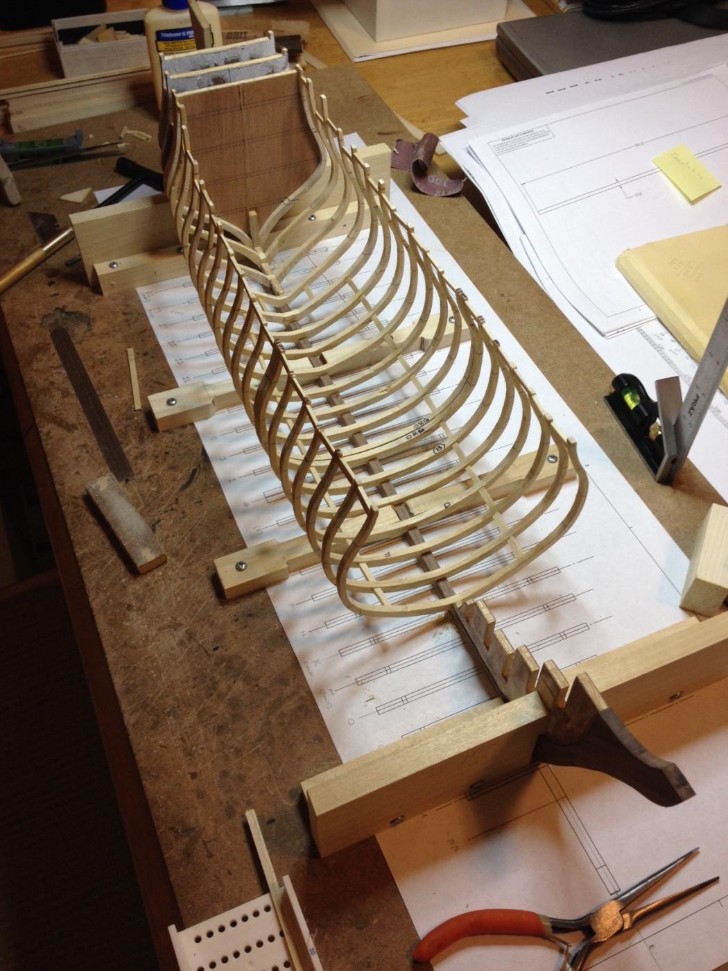
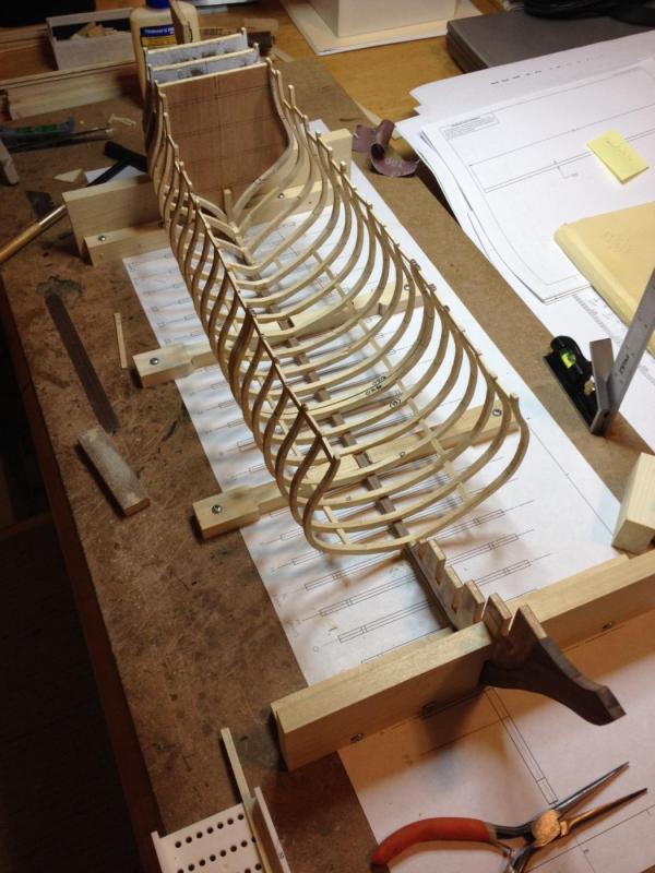
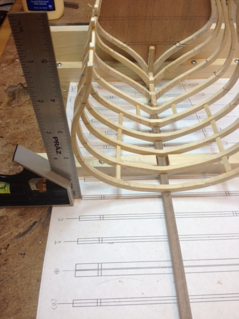
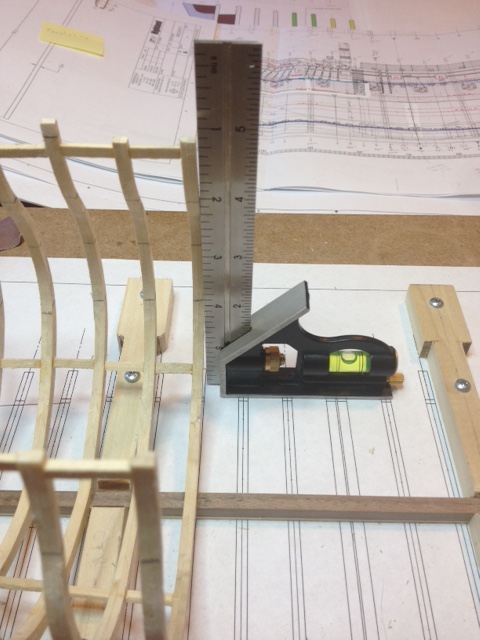
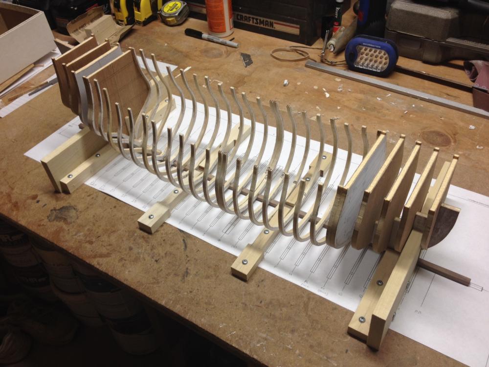
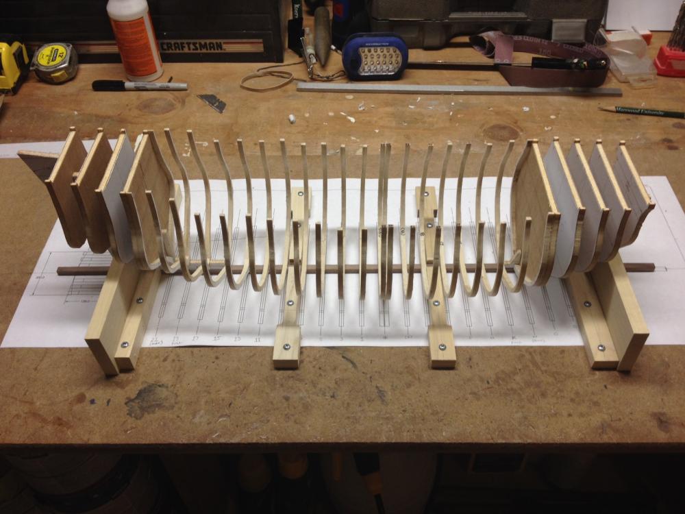
Progress update. I started to glue the frames in place in the past few days. Instead of making a framing jig I opted to go the old fashion way with a couple of square blocks and a 6" square. I figured it was going to take a lot of time and effort to make an accurate jig that I will just toss later. If the frames are made symmetrically, I can put down a top view drawing layout of the ribs on the build board and position it with the keel fixture. Once the first rib is in place and squared up, I use spacers to position the next rib along the keel. If all is correct, they should line up with the drawing below. I use the 6" square to true up the faces and the out ends with the drawing lines. To me it seems much faster and easier than the jig. Here is where I am today. Pic showing how I centered the frame on the keel (port to starboard). If the edge of the square sits even with the edge on the drawing and the frame itself, life is good. The other side should fall into place provided you did a good job making the frames symmetrical. I then squared up the frame aft to bow. With spacers precut to the same length and if the frame is straight all should line up. I check it with the square. The edge of the square should be lined up with the face of the frame on the drawing and touch the lower and upper face of the frame. If it does, once again, life is good. As a second quick check, I use a square block to check squareness with the keel. Tom
- 385 replies
-
- 13
-
-
G'day John, Don't even think about packing up and retiring! You are one of my many inspirations on this site. It really is my second build and I have to admit that I am already freaking out about the carvings of the figurines even though they are a ways off. I have never done that before. I am thinking 5 pound bucket of sculpey should be enough to get one done... . But for now, I am still in the shallow end of the pool. Tom
-
mmdd, Thanks for the encouragement and the beautiful photos. It is really nice to see such a wonderful build. As an added bonus, the pics give me a much better understanding of what everything looks like. Thanks again for sharing and even though I am two years late, congratulations to Larisa. Tom
-
Thanks Bluto, I hope you have a lot of patience. But then again you must if you are in this hobby. I am not exactly a speed demon, especially in the summer. Tom
-
Hi Mark, I am using the frames in the middle because I plan on opening up one side of the hull to see the lower decks. The ends where the bulkheads are will be fully planked on the outside. The first post on this thread shows the rough cut out I plan on making. I think I will eliminate the "tab" of planking I was going to leave on the upper side. I was thinking I wanted to include all the steps down the side of the hull. After further thought and since there will be a full set of steps on the other side that is fully planked, I am going to make the cut out a basic rectangle type shape. Tom
-
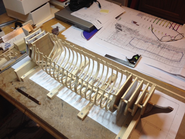
I finally got around to putting together a build board to hold the keel while I start the frame assembly process. After I received an order of wood from Jason at Crown Timberyard I am ready to start. I purchased some maple for the decks, Swiss pear for the outer planking and some walnut for some of the wales, keel and stem. It was my first purchase from Jason and I was quite impressed. I dry fit the frames/bulkheads I had previously built just to get an idea of what I am getting into. It seems like it is going to be a fun ride.
- 385 replies
-
- 14
-
-
Getting close now! Looks good. Tom
-
One man's scrap is another man's gold... or in this case wood. I will definitely check into this. Thanks for the tip. Tom
-
Hi Sam, I just hope the water is deep enough!! Glad to have you along for the ride. Tom
-
It seems to be coming together. Keep up the good work. Tom
-
I put some small brass pins into the edge of the walking boards and pinned them into the hull along with some wood glue. Tom
-
Jp, Just checking in to see how she is coming. Glad to see you back at it. I put all the standing rigging in first to "lock" all the masts in position including the shrouds. As far as the ratlines, the next time I do them I will wait until the running rigging is complete. It seems it would be easier to work and get into the belaying pins and such. If the running rigging ends up pulling something out of wack or loosens up a standing rigging line, I think it would be easier to retie the standing rigging line than redo the running rig line. Just my opinion. As Mark said earlier, everyone is different and you just go by "feel". Tom
-
Where there's a will there's a way. Overcoming obstacles using ingenuity is half the fun of this hobby. You will feel that much prouder in the end. After all, in this hobby it is what you see, not what you "know" that really counts. Tom
-
Thanks everyone for the encouragement. I just started ripping planks for the inner hull from left over wood (poplar) from past furniture projects. Bought a 9" bench top band saw and turned my drill press into a drum and thickness sander. I guess the old adage "Necessity is the mother of invention" is true! I put a couple of home made rip fences on my saw and drill press and now I am making planks to whatever width and thickness I need. My next tool purchase will most likely be a "real" thickness sander but I would rather spend my limited budget on wood and such right now. My homemade setups work just fine for now. I still need to buy some walnut for the keel, stern post and bow stem. Once I get that I can start assembling frames. I plan on getting a piece of 3/4" maple from Home Depot and ripping/sanding it down to make the deck planking but that will come later. I am also planning on some pear or cherry for the outer planking. Leaning towards pear. That should keep me busy for while. Tom
-
Wow Mike, that looks fantastic but I am not really surprised. The color scheme with the copper plates really works. Keep up the great work and keep the pics coming. Tom
-
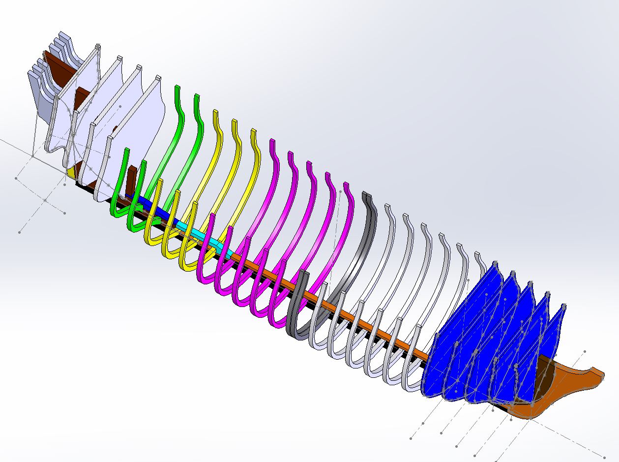
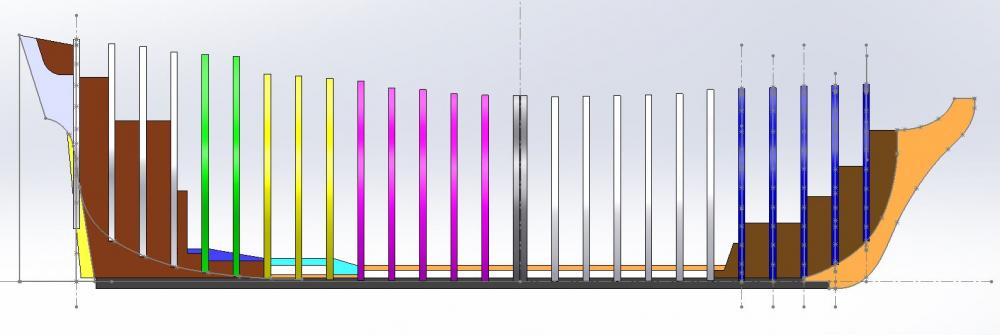
It has been a bit slow going in the shipyard as of late. Too many major soccer (futbol) tournaments that need to be watched! I have been modelling my framework to give me a better understanding of how things will go together with this build. Below are some snapshots. Being my first scratch build there is a lot to learn and research... but everybody here at MSW already knows that. I hope to put an order in for the deck and hull planking wood in the next week. In the mean time I have some bulkheads to finish up. I need to set up my build board and then the assembly process can begin. Enough planning and layout work! It is time to make sawdust!

- 385 replies
-
- 17
-
-
Pandora by marsalv - FINISHED - 1:52
toms10 replied to marsalv's topic in - Build logs for subjects built 1751 - 1800
And the bar just keeps getting higher and higher. Incredible job. You are leaving the realm of hobbiest and entering artist. Tom -
I have only rigged one ship so far but I did enjoy it. After working on the hull for a year it was a welcome change. I think the rigging is what gives a model the "wow" factor. Tom
-
Mark, Thanks for the tip. I am thinking along the 1.5X also... at least for a minimum. Better to much than not enough. Tom
-
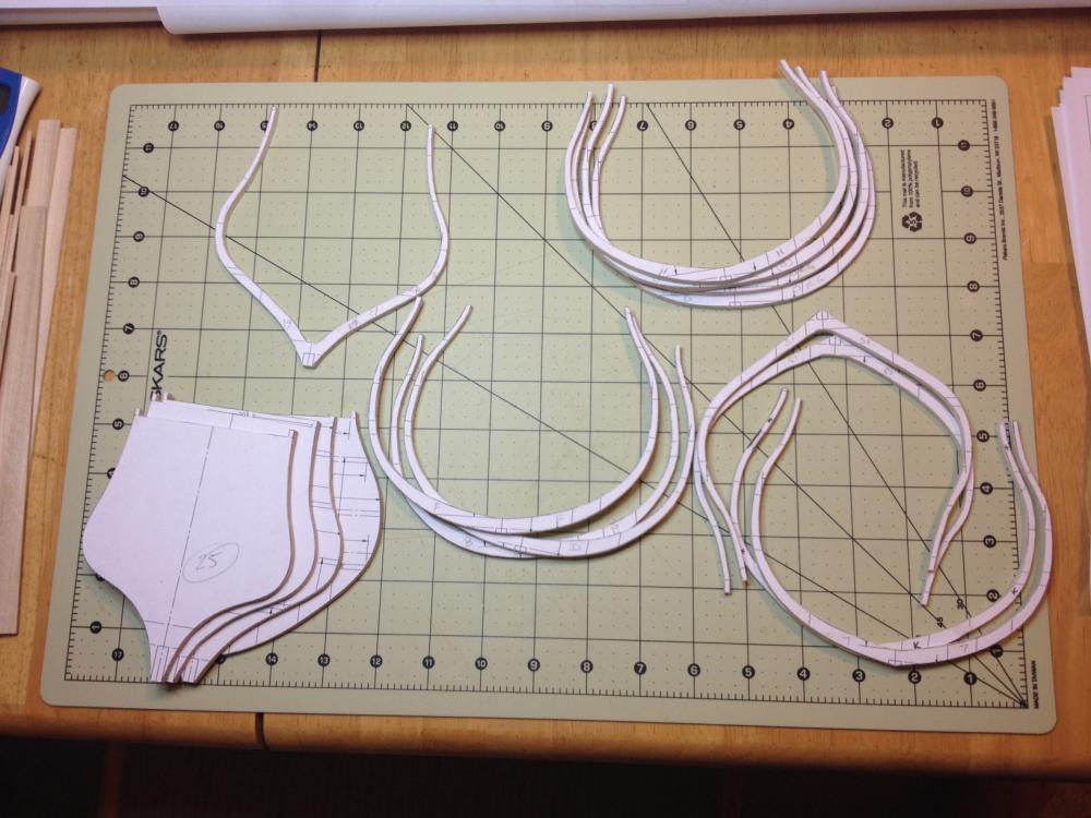
Had some downtime this weekend so I made some of the frames and bulkheads. Still have to cut out the notches for the keel and make a few more frames and bulkheads for the bow area. As I mentioned the bulkheads will be used starting where the canted frames begin. I also need to start thinking of the type of wood for the hull planking, keel & stem. I am probably going with maple for the decking with a light stain and walnut for the keel and trim. Still up in the air about the hull planking. Also need to figure out how much of each to order. Tom
- 385 replies
-
- 13
-