


ir3
-
Posts
321 -
Joined
-
Last visited
Content Type
Profiles
Forums
Gallery
Events
Posts posted by ir3
-
-
-
It has been too long since the last update. I finally have the steam plant running. This is my first run outside the boat. I need to get more experience on running the plant as there is a gas pressure regulator which needs adjusting and I need to know how open the steam valve from the boiler should be for efficient running. Hopefully the video of the first steam run will come out OK.
More to follow.
-
-
-
-
-
-
-
Hi Colin,
There will be a link to "Start a new topic" next to "Reply to this topic" at the top of the page. Just click "Start a new topic" and follow instructions. The category that this thread is in is called "Kit built logs for subjects built from 1901 - present day". Looking forward to seeing the start of your thread. The stand does not come with the kit. Outlines are on the plans. You should post pictures of everything you have so we can get you on the right track to acquire the missing parts. Hope this helps.
- lmagna, Ryland Craze and mtaylor
-
 3
3
-
-
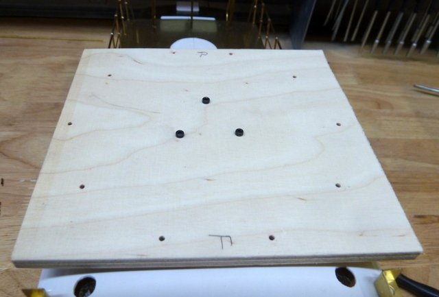
All the holes for railings and other items have been drilled and backed with some scrap wood. The last part of the animation for the cabin is the mechanism to rotate the searchlight and loud speaker assembly. This was not as easy as the plans and instructions show. I probably spent about 8 hours working out the geometry. If you were able to position everything as per the plan and get the lengths exactly the same it would have worked out just fine. If there is any error in the positioning and length of the parts, the mechanism will bind somewhere in its travel. So several hours of experimenting finally got me to the point where the searchlight goes through about 145 degrees of rotation with no binding. Glad to have that out of the way.
Now it is time to prep the cabin for painting as well as all of the pieces that get attached to the cabin.
Until next time,
IR3
-
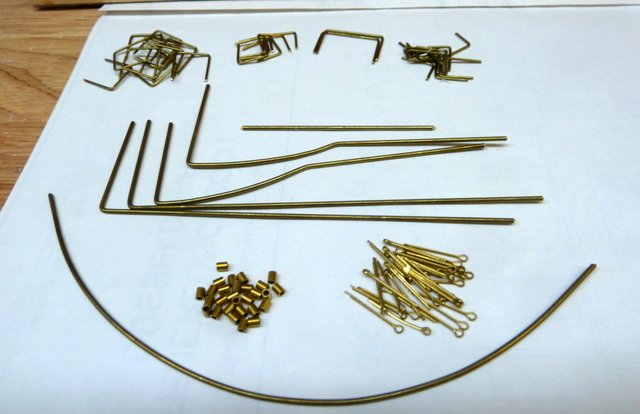
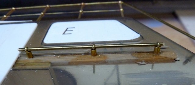
The end is near for the main cabin construction. All the railings, grab handles, steps, and mounting goodies are all collected. One example of the railing installation is shown in the pictures as well as all the other goodies. The Mission Models Grab Handler came in very handy.
Next update will be with all the holes drilled for the railings and steps for the cabin railings. Getting close to painting this puppy!
Until next time,
IR3
-
The other half of the railing took less than 2 hours. There is still a bit of tweaking to be done but that will happen when the permanent installation takes place. The exact height of the railing can be set and the two aft stanchions be cut to length. Now it's off to setting up the grab rails around the main cabin doors and the along the sides of the cabin. It's getting close to painting time and final assembly.
Until next time,
IR3
-
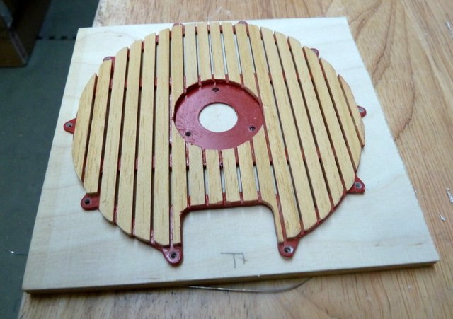
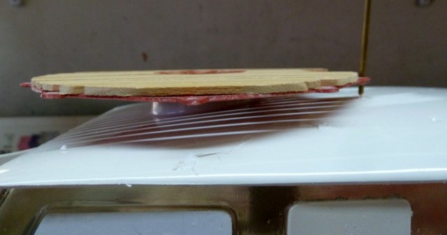
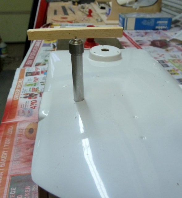
Thanks John, much appreciated. I made a jig to build up the railings for the upper water monitor. This is not an easy task. The first step was to layout the holes and drill them.
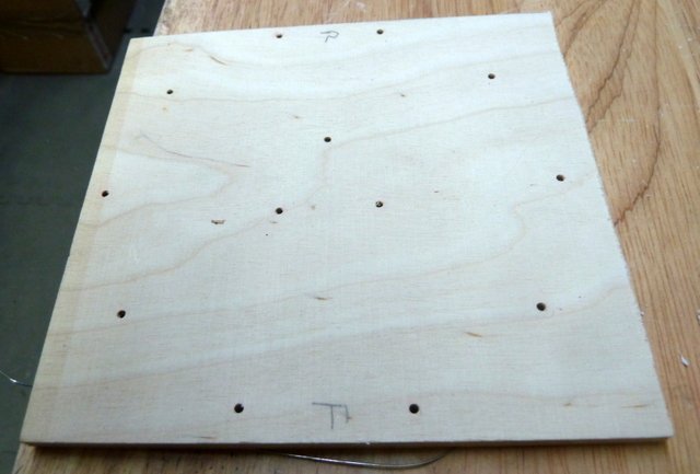
Next, fit the stanchions and the railing then solder.
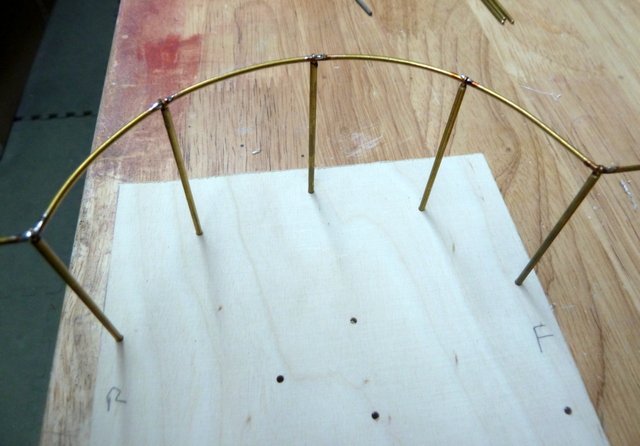
Then the jig was bolted to the top of the cabin.
Finally the railing was inserted to mark the spots on the cabin roof where it needed drilling. When I then inserted the railing, nothing was aligned properly. There are several problems doing this operation. The first is that bolting the jig to the top of the cabin, while maintaining proper alignment, the cabin roof is so thin that it is almost impossible to stabilize the jig. So drilling straight down is still very problematical. The top of the cabin is slanted in the areas where holes needed to be drilled and even with the jig in place, the drill tip tends to wander. The only solution to get the stanchions vertical was to enlarge the holes slightly and re solder the tops to get them vertical. It is pretty close now and the flaws are not obvious.
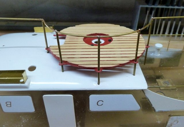
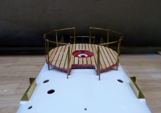
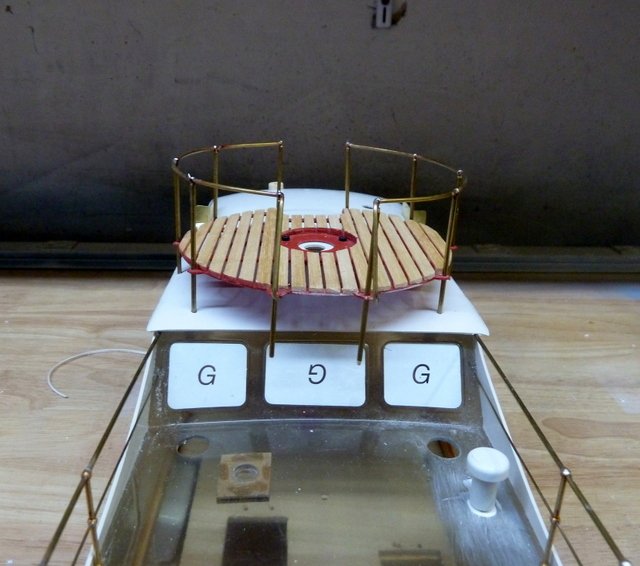
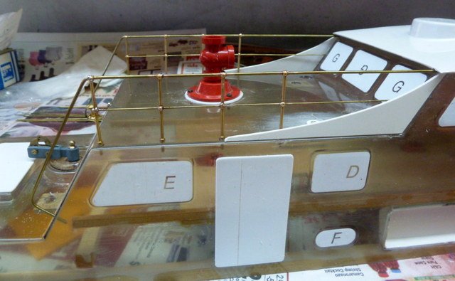
The platform is very flexible and getting the railing height is a bit of a nuisance but I'm gaining on it. All of the stanchions are actually vertical. The picture doesn't show it. Mounting this platform was not one of ROBBE'S best efforts. I can see why the box art shows the railing in place without the tabs.
So now I need to form the front end of the railing where it goes into the cabin roof and the back end which forms into a grab rail when climbing up the to roof. Then its off to the other side which should go a lot faster since I know all the pitfalls.
Until next time,
IR3
-
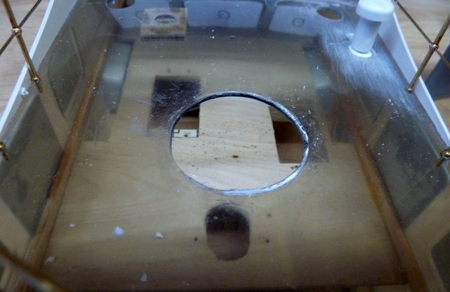
The railing for the aft Fire Monitor is now complete. This was not an easy job with all of the bends and curve and fitting to the cabin. The picture shows the first holes drilled into the sloping section of the rear cabin which were in the wrong place. A bit of filling and sanding before painting. I found that the rear fire monitor was not centered and the problem went way back to the start of working on the cabin. There was a picture showing where some areas of the cabin needed to be removed. I misinterpreted the picture and cut out the mount for the rear fire monitor. The fix shown in the previous post but the monitor is off center. I need to cover this hole and re center Fire Monitor base. Read the instructions three times, look at the pictures three times, look at the plans three times and don't cut!☹️.
Now it's off to repairing the big hole and getting the railings around the forward fire monitor.
Until next time,
IR3
-
Thanks John, this Robbe Kit is a pleasure to work with. Excellent instructions and plans. The parts are superb.
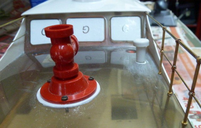
The main railings for the mid cabin deck are finished. The biggest problem is drilling the holes in the cabin wall to steady the railings. The railing on the port side of the cabin is straight, just bad camera angle. Two new pictures showing the tow hook and the repaired mushroom ventilator. Next job is to make the safety railing for the lower Fire Monitor.
Until next time,
IR3
-
Today it was adding a few more lights, the towing hook, and a load of ventilators. Of course, all in the rough. There is a lot of painting (UGH) coming up. One of the pictures shows a patch from an error. I drilled a hole a bit to big for on of the ventilators. It is patched but the filler needs to harden. That will be remedied in the next session. The cargo hook is very cleverly spring loaded to keep it closed. Better pictures on the next update.
Now it is off to railings. Lots of railings.
Until next time,
IR3
-
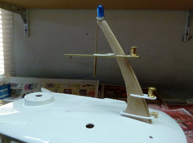
Continuing work on the cabin accessories. The mast with lights and antennas is finished in the rough. It needs light bulbs installed and paint. Note: the picture shows some distortion but all the parts are square. Photography is not one of my strong suits.
There is an issue with the platform for the top Fire Monitor. The plans call for rail stanchions to pass through tabs on the platform and through the cabin top. I tried various methods trying to keep the drill perfectly vertical while drilling but no luck. The roof is not flat anywhere so the drill tends to wander. I tried using a scribe as vertical as possible to make a center punch hole for the drill but with my eyesight this was a no go as well as making a jig to keep the drill vertical. If I had a suitable machine shop I could make a thick metal plate with the exact outline of the tabs on the platform and get the holes drilled but I don't. The box art shows the rail stanchions do not pass through platform tabs. In fact, the tabs do not even appear on the platform in the box art. I will do the same. Since the platform is bolted to the top of the cabin, it will make it a lot easier to repair the Fire Monitor if needed.
Now its off to a few more cabin details including vents and other goodies.
Until next time,
IR3
-
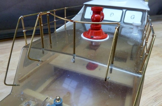
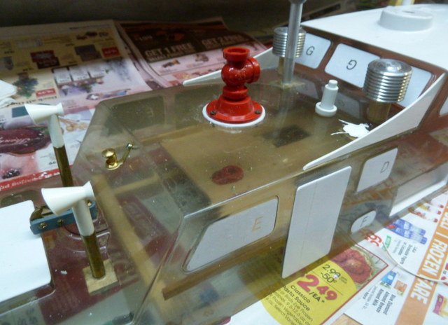
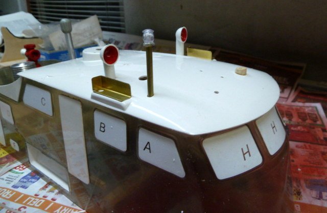
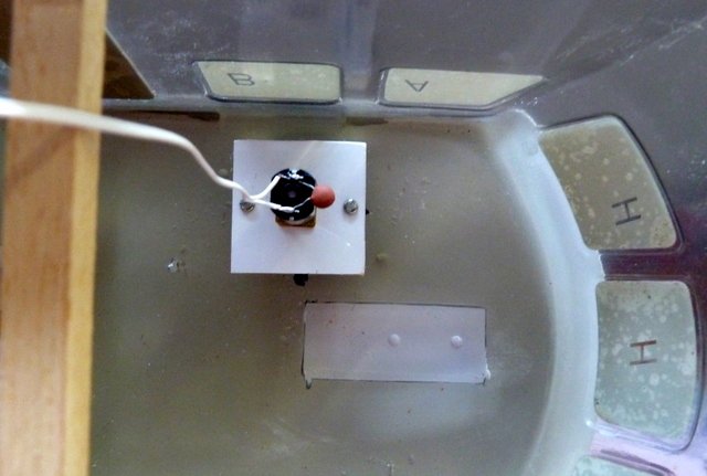
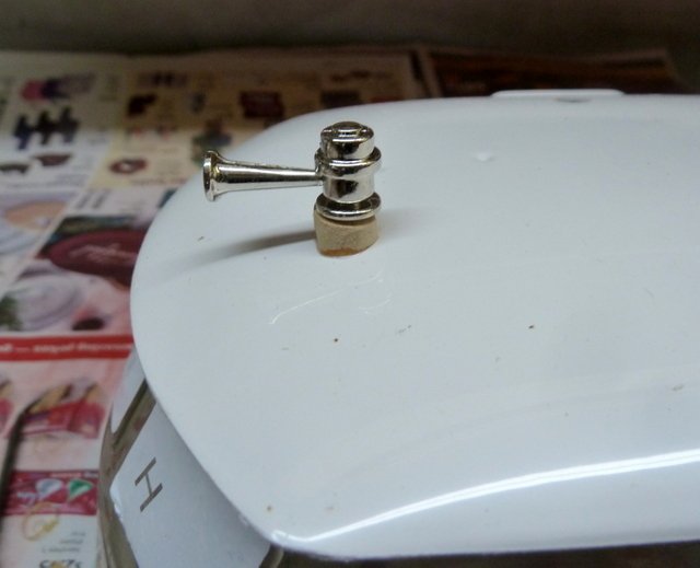
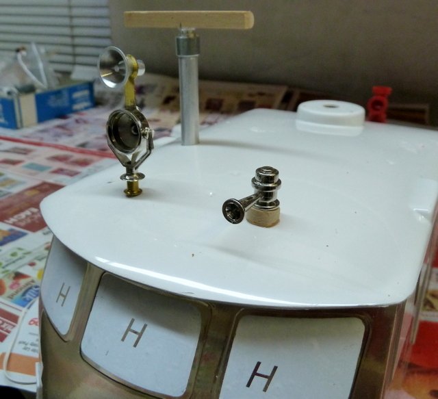
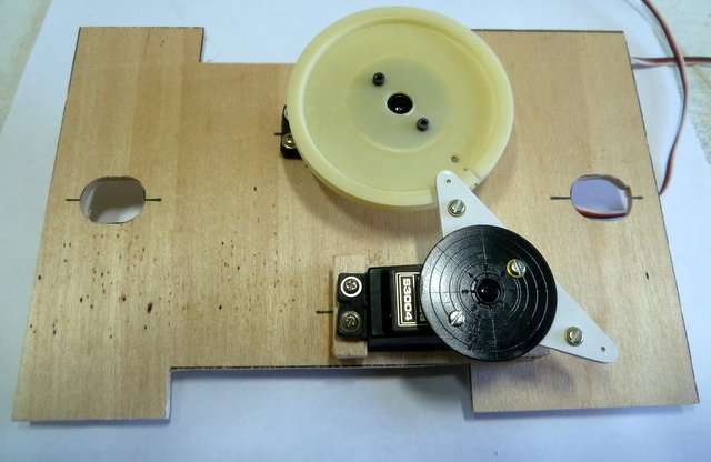
The radar, search light/loud speaker, and the horn are installed in the rough. The radar rotation motor is in the cabin and the search light/loud speaker is ready to install. There is a mechanism within the cabin to move the search light which needs to be installed. The horn base needs a bit more shaping. Drilling vertical holes through the cabin roof and the internal top of the cabin is quite difficult. Getting verticality requires drilling the holes close to the right diameter and finishing with a round file. Very tedious. I had to fill a bunch of holes with Sprue Glue and re-drill.
Next update will have the rotation mechanism installed for the search light.
Stay safe,
IR3
-
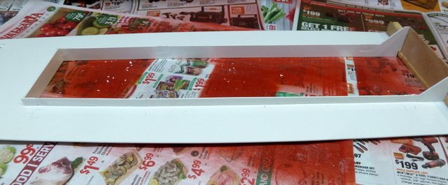
The glue for the servo tray has set over night and I removed the diagonal brace. The cabin remained solid with no flex in any direction. I removed the two cross braces and had no problems with flexing. The interior cabin cross braces were installed to maintain the spacing so the cabin will fit on the main deck opening. It appears, in hindsight, that the bracing used to square the cabin allowed the servo tray to maintain cabin rigidity. The slots in the main deck hatch coming were filled and now no worries about water leaking into the hull. One big headache avoided. I am in no rush to get the main deck in place for now. The kit has a board that is used to hold all of the RC electronics but it is based on having the components that were available at the time the kit was produced. Not having the old components, I need to collect all the relay modules that are usable and come up with new layouts. It may take two boards to hold the parts and location within the hull will have to be worked out. More on this in the future. For now, I will be working on everything associated with the main cabin.
Until next time,
IR3
-
Spent most of the morning installing the rails and aligning the servo tray for the two Fire Monitors mounted on the cabin. Aligning the rotational shaft bearings was a bit problematical since I needed to maintain smooth rotation. They are both in and the rotation on the forward monitor is a bit tight so some light filing should work out just fine. The servo that raises and lowers the nozzles on the Monitors is interfering with the cross brace so I may need to hog out some of the brace to clear the servo horn. The servo tray is not yet glued in and I am thinking that once glued in, it may just be enough to keep the cabin straight and the cross braces will not be needed. There are two cross braces that should be installed in the cabin per the plans. More on this to follow.
Until next time,
IR3
-
Thanks for the heads up on both the main deck opening and the anchor winch. Two more items on the long to do list for this model.
Some more work on the main cabin. Things like doors and hatches have been glued on and the cabin roof. The initial installation of the Fire Monitors is complete. I need to get this done so I can correctly locate the servo plate for rotation and elevation. More 30 RPM motors have arrived so I can also get the radar and rotating search light installed. Lots to do on the cabin.
Until next time,
IR3
- lmagna, Old Collingwood and mtaylor
-
3
-
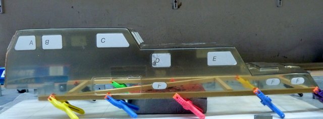
I trimmed the bottom of the cabin and fit it to the deck. The fit on the port side is quite nice up to 2/3 back. Then there is a gap. This is due to the aft portion being so poorly molded or removed too early and the aft part of the cabin assumed a non fixable shape. The starboard side has the same problem. Not sure how I am going to fix this as of yet. I might be able to add some polystyrene sheet and work in the correct shape and clearance. More to follow. suggestions would be appreciated.
Until next time,
IR3
-
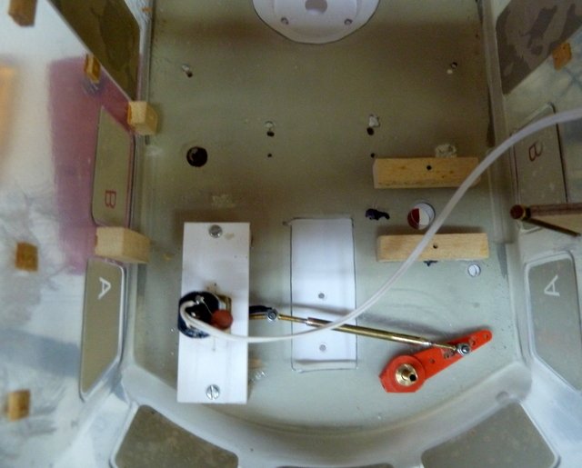
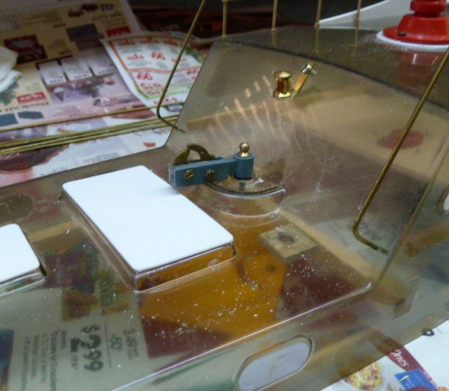
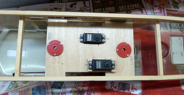
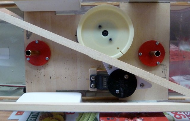
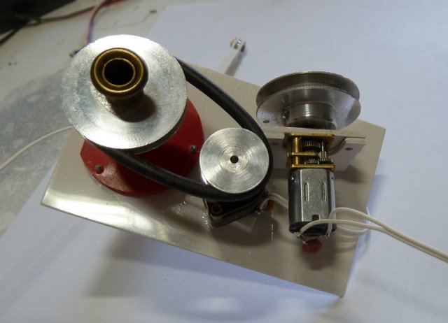
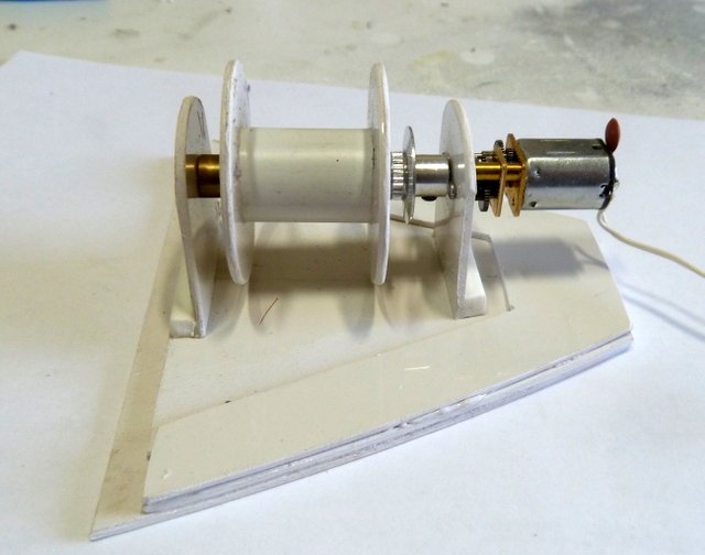
A bit more progress. The 50RPM Robbe Motor has been replaced with a 30RPM motor for the boat crane. The anchor winch power lead and capacitor are done. I started on the main servo controls for the two Fire Monitors on the cabin roof. They will both move at the same time and are controlled from two servos. The one with the pulley is used for rotation and the the other is used to raise/lower the nozzles of the Fire Monitors.
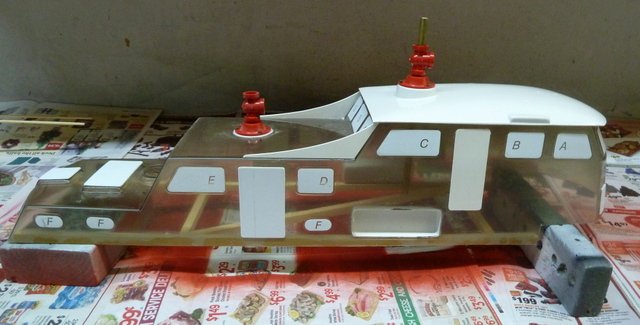
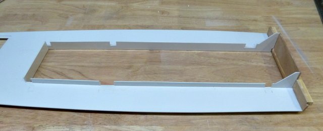
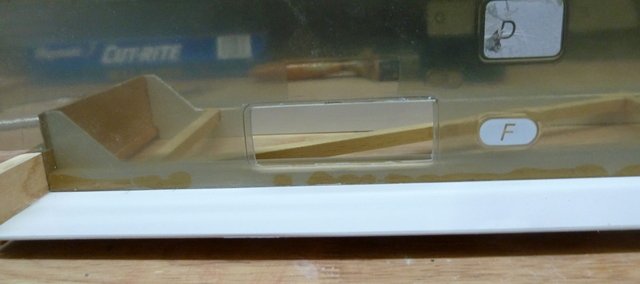
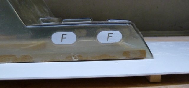
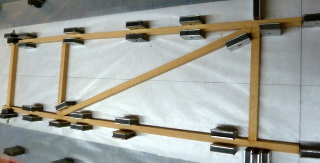
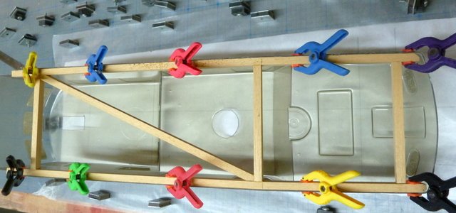
I started on the cabin and ran into a major problem. The cabin is completely racked. I tried some heat treatments and twisting to solve the problem but no help. It turns out, however, the cabin is perfectly straight when it is lying flat on the work table. To maintain the shape of the cabin and provide a good seating on the deck there is a frame around the bottom of the cabin to keep it straight. To solve the extreme warping of the cabin I decided to build a box structure that conforms to the shape of the bottom of the cabin. It has cross beams and a diagonal to help ensure the cabin will remain straight. After clamping the cabin to the box structure, the cabin is perfectly straight. I will have to cut some notches in the opening surround of the main deck to allow for the cross beams but it will work solving the warpage problem. I will be gluing the cabin to the structure and start installing the Fire Monitors.
Until next time,
IR3
- Jack12477, lmagna, Old Collingwood and 1 other
-
4
Model Shipways USF Confederacy Kit NIB -- Sold --
in Traders, Dealers, Buying or Selling anything? - Discuss New Products and Ship Model Goodies here as well!!
Posted · Edited by ir3
Dropped Price
I have a Model Shipways USF Confederacy Kit for sale. I have so many projects that need attention that I do not think I will get to this magnificent model. I built one many years ago and passed it on to another modeler. Being impulsive I thought I would do another but it won't happen.
Asking $400 plus shipping. Please ask questions and thanks for looking.