


ir3
-
Posts
336 -
Joined
-
Last visited
Content Type
Profiles
Forums
Gallery
Events
Posts posted by ir3
-
-
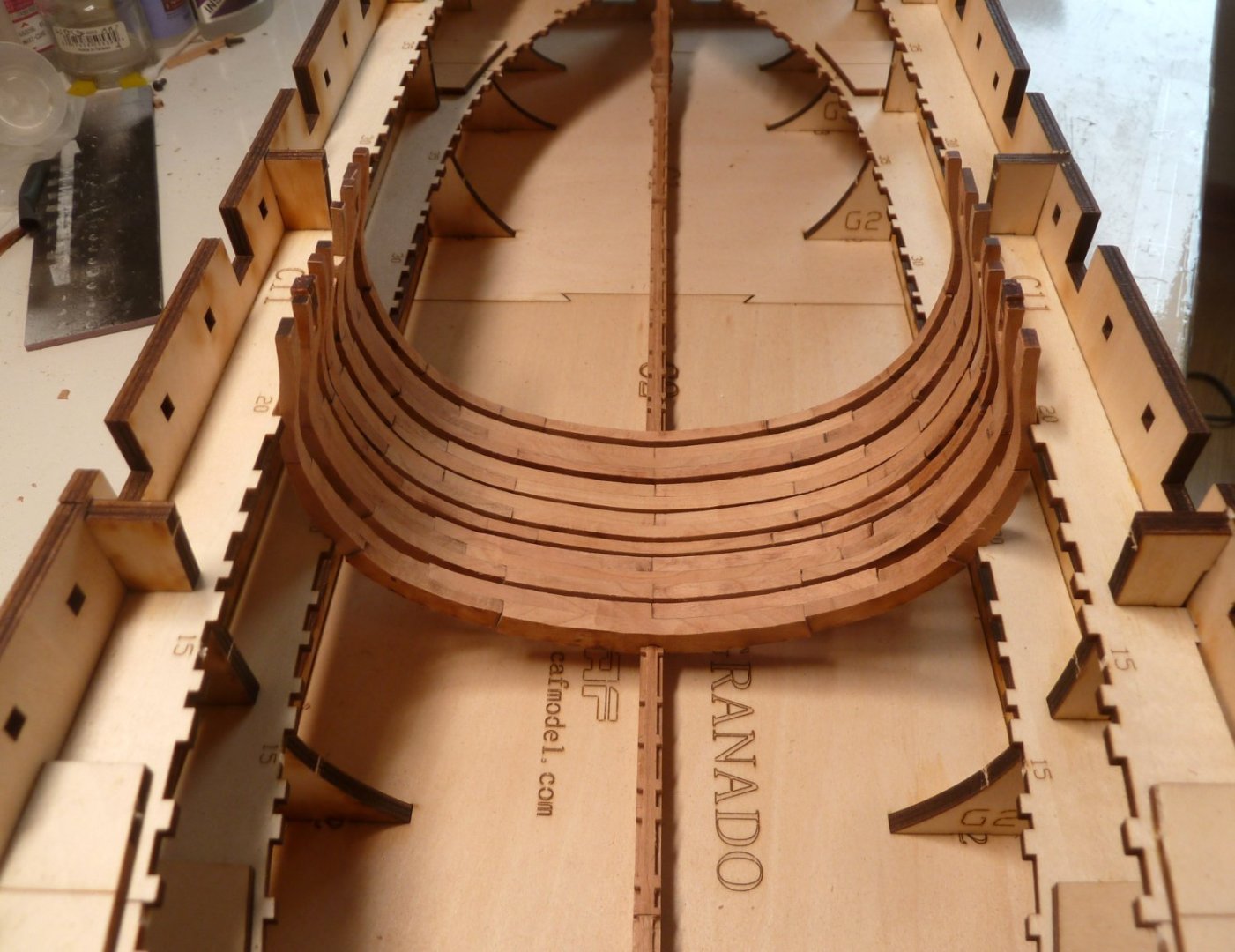
We're gaining on it. Frames 20 - 26 were built off the plans and needed extensive rework to get them to fit. It took a considerable amount of time, but lesson learned. From this point forward, each frame will be built on the plan and installation should take a lot less time and go much smoother.
-
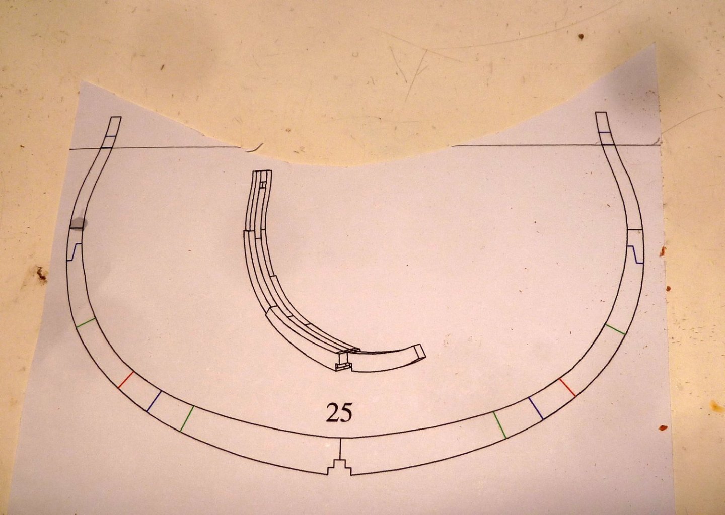
Still learning. When assembling the 4-layer frames over the plan, the hole near the top of the frame must be spot on. This determines the exact height of the frame within the building jig. I did not notice this when I built frame 25, just a bit hasty and not reading the instructions several times.
- scrubbyj427, mtaylor, Ghost029 and 1 other
-
 4
4
-
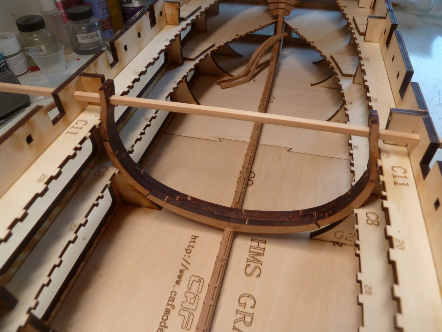
Lessons learned. Build each frame over the plan to make sure it is not too wide. Fit the frame to the keel. Adjust the slots in the jig as needed to slide the frame in. After correcting frame 25 and widening the slots in the jig, the frame fits nicely. Forty plus frames to go.
- allanyed, ccoyle, scrubbyj427 and 6 others
-
9
-
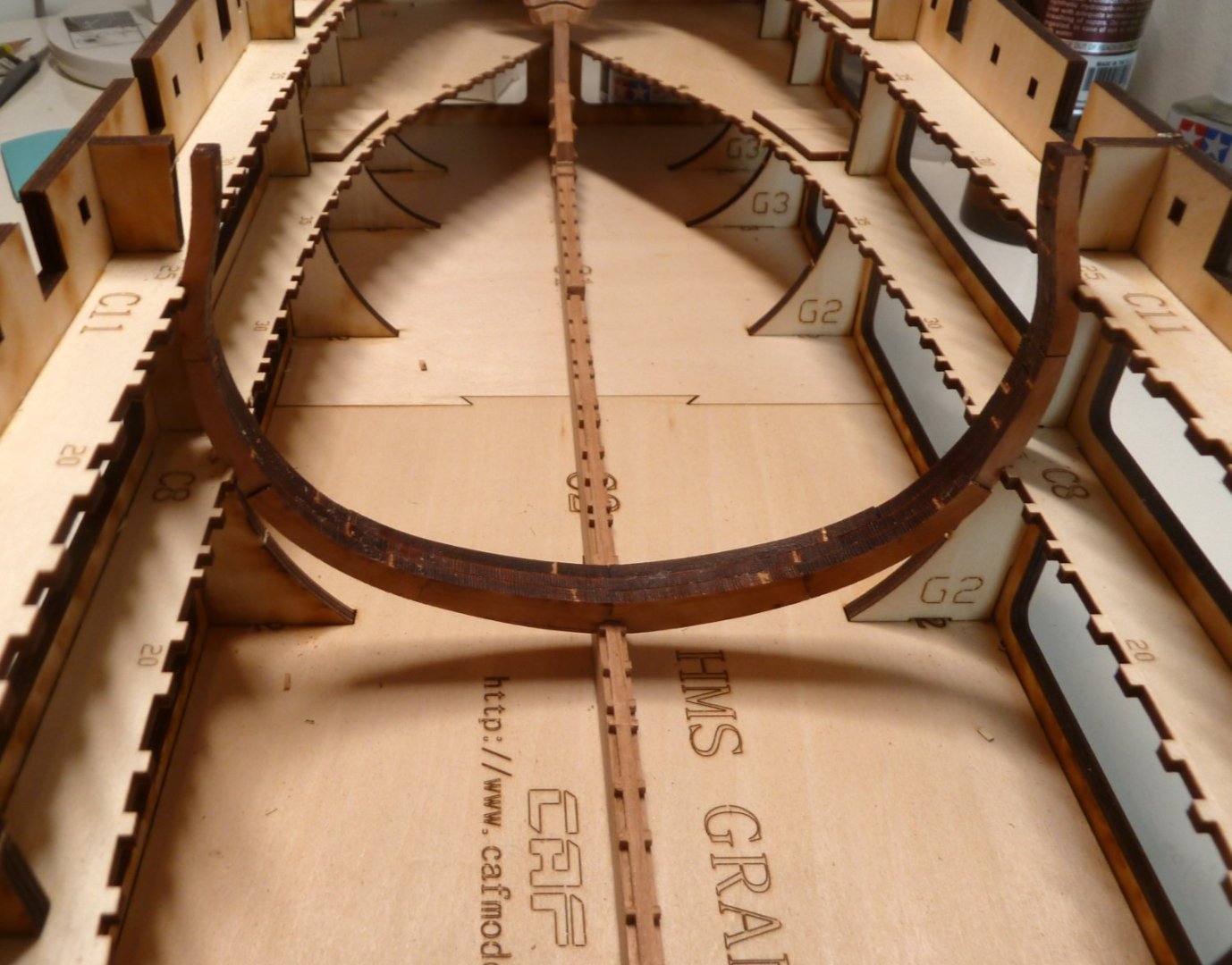
I think it would be a good idea to build all the frames that sit directly on the keel. I think the instructions allude to that. Make sure each frame fits in the slots in the assembly jig. The only problem is that if the slots are not wide enough which was one of my problems, after widening them there may be a question of keeping the frame vertical. But if the frames properly fit in the jig slots than it should only be fine tuning if the frame does not slip in smoothly. My problem is even after cleaning all the laser burn off rib 25 and widening the slots, it still will not slide in unless a lot of force is used. I just didn't want to go through all this with 40+ ribs. It should be going a lot smoother than I experienced.
-
Well, I tried to install frame 25 into the jig and there is no way it is going to happen. This kit is way above my pay grade, and I am just bringing it to an end. I am very happy for those that have managed to get the frames installed but there is a skill here that I just do not possess. My adventures into trying a wood ship model like this is over. Thanks for the encouragement.
- ccoyle, HardeeHarHar and mtaylor
-
 3
3
-
For sure. I see a lot of work in the next few weeks fitting the frames, but well worth it.
-
I am back on the Granado build. I received new parts for 5K and 5L but installing them was a real headache. They are in but need a lot of work to get them right. Frames 53 sort of fit so some work to do there. I decided to make some frames to learn how to get the frames in the jig and how the various types of frames are assembled. I started with a mid-ships frame and found the following problem. The frame is 13mm wide and the plan shows they should be 13mm wide. The notch in the keel is 12.5mm. Do I narrow the frame or widen the notch. Widening the notch seems to be the best solution. Also, trying to put the frame in the jig, it just does not clear and it is going to take too much force to get the frame in place. This will make it difficult to remove after all the dry fitting. How have you building this model dealt with these issues.
- BobG, JeffT and Beef Wellington
-
3
-
I watched the documentary "Patagonia" on NETFLIX, and I can understand your love for the area. A most remarkable preserve of a wide variety of animal life and very pristine. Your photos do it justice. Very nice.
- FrankWouts, Dave_E and glbarlow
-
2
-
 1
1
-
Thanks for the encouragement from all the responders. I am always a bit hasty by fault. CAF is sending some new parts and when they arrive, I will give it another try. They are currently held up in China Post and it may be weeks before they move through the system.
- mtaylor, HardeeHarHar, ccoyle and 2 others
-
5
-
Sorry to all that have been following my attempt at building this model. It is way above my building skills, and I just cannot continue building. It is not enjoyable for me anymore. I think CAF did a very good job designing this kit, but it takes a craftsman with a lot more skills than I have to build. Thanks for the encouragement and the likes. This is just not going to happen.
-
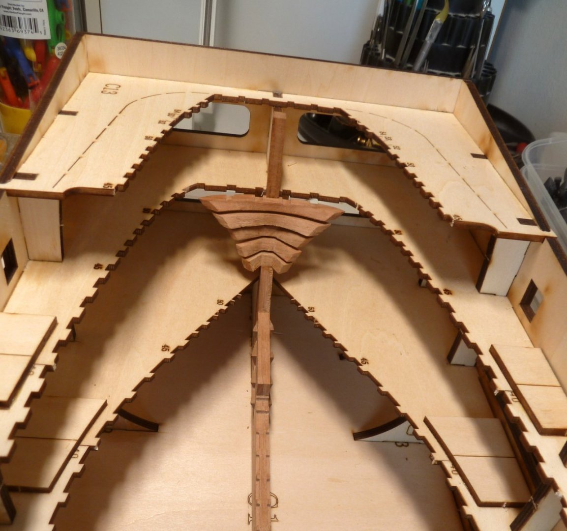
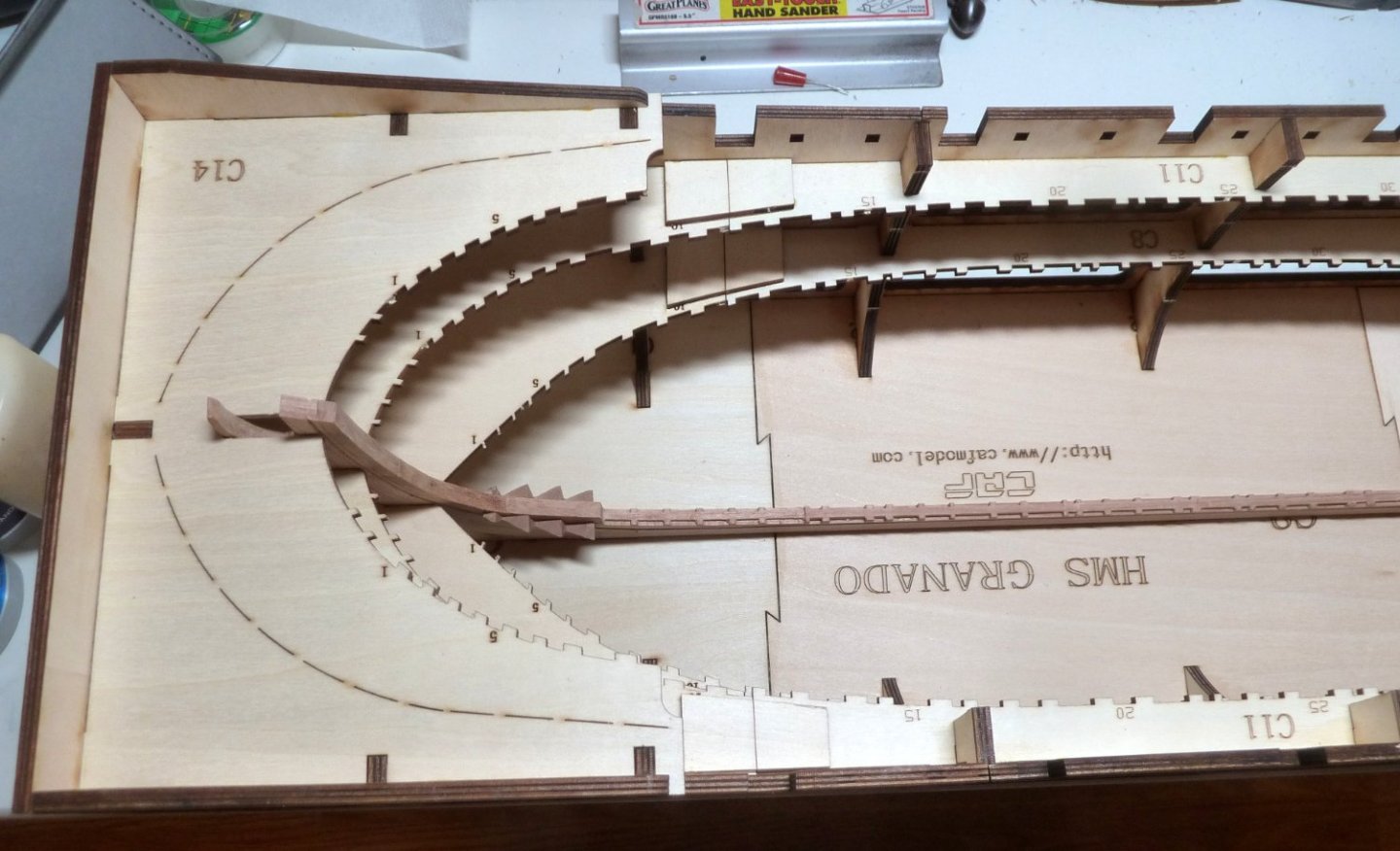
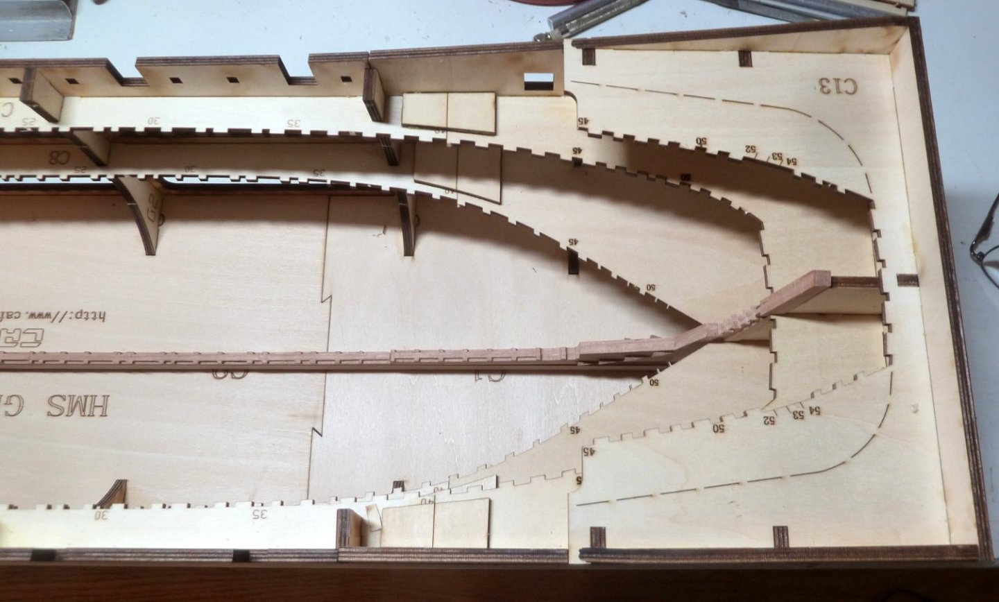
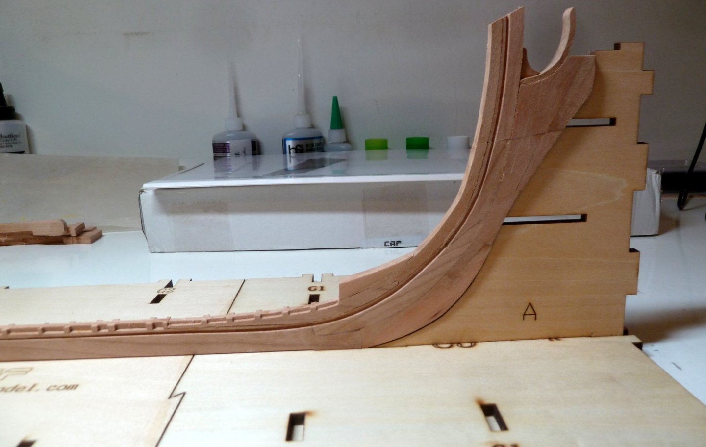
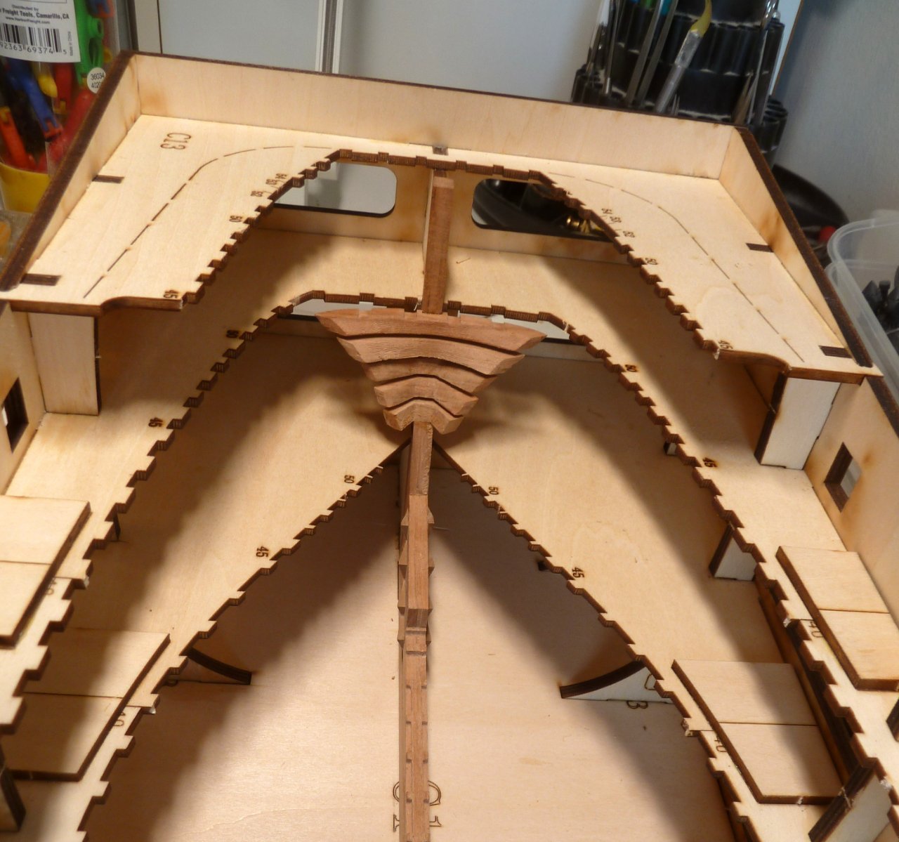
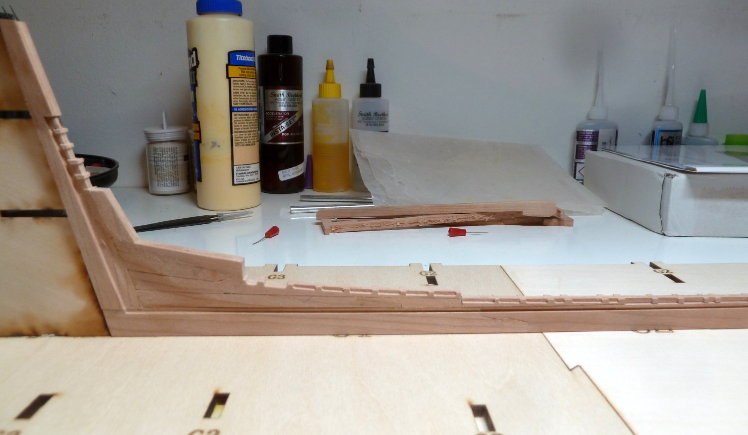
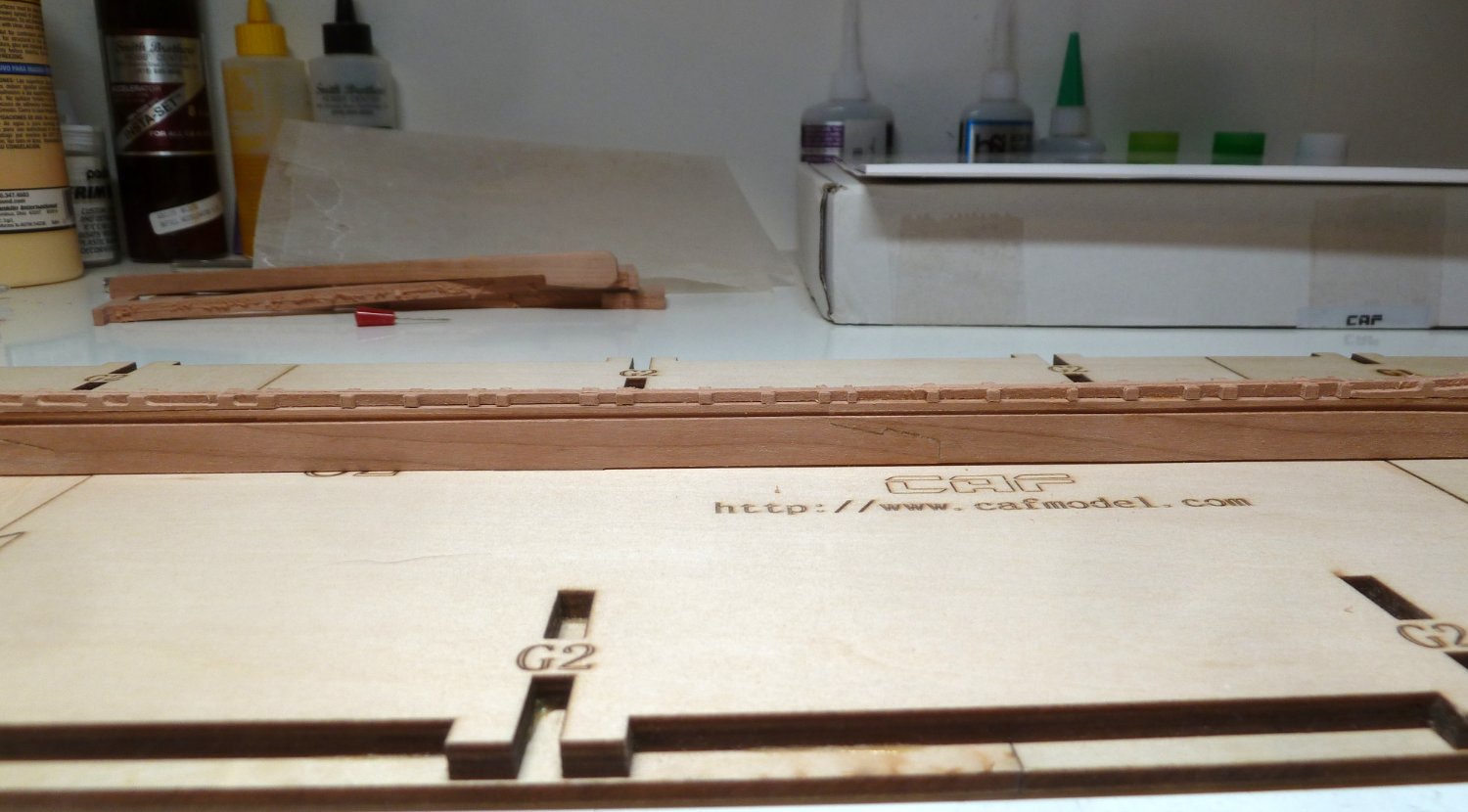
I spent the day assembling the building jig. Just a few observations and cautions. In step 12 of the instructions, do NOT glue A and B onto baseboard. It will make it impossible to assemble the jig. It is just to make sure the stem and stern post are oriented correctly. I am not too sure about step 13 as there shouldn't be any ribs/frames assembled yet. After steps 14, 15 and 16 make sure the assembled keel still fits. I didn't and it took me quite a while to sand and adjust the slots to get it to fit. I couldn't figure out how to get the keel into the jig. Parts C13 and C14 have dashed lines laser cut into them. The stem goes underneath C14 to lock it into place. When the ribs/frames are installed the only way to get the hull out of the jig is to cut along the dashed lines. This will allow the entire hull to be lifted out. Assembling steps 17 - 19 may take a bit of fitting. Although the pieces are very close to matching, assembly tolerances will require some fine tuning to get the pieces together. The assembly of the jig stretched my patience, but it is finally together.

- Beef Wellington, Prowler901, CiscoH and 5 others
-
8
-
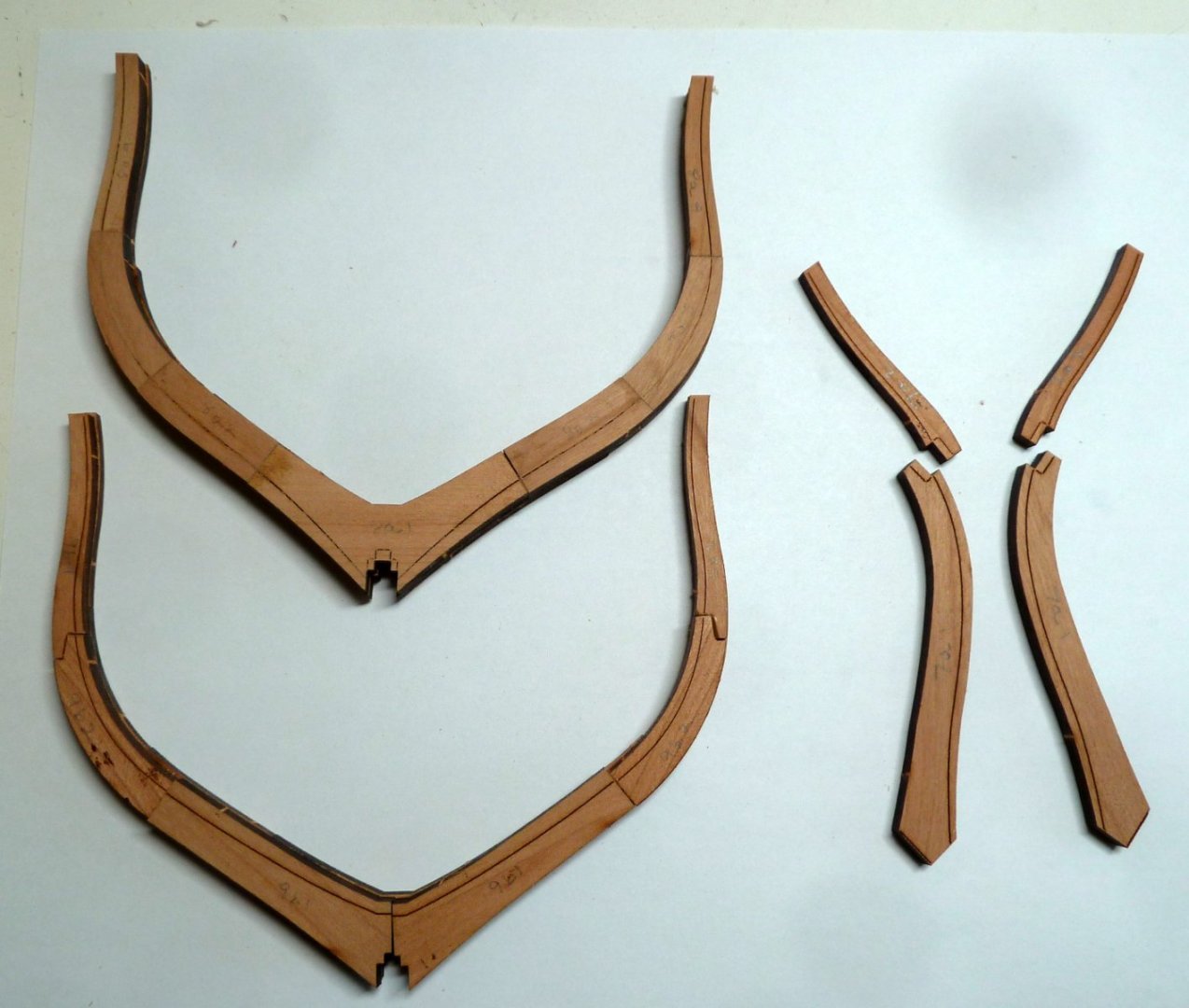
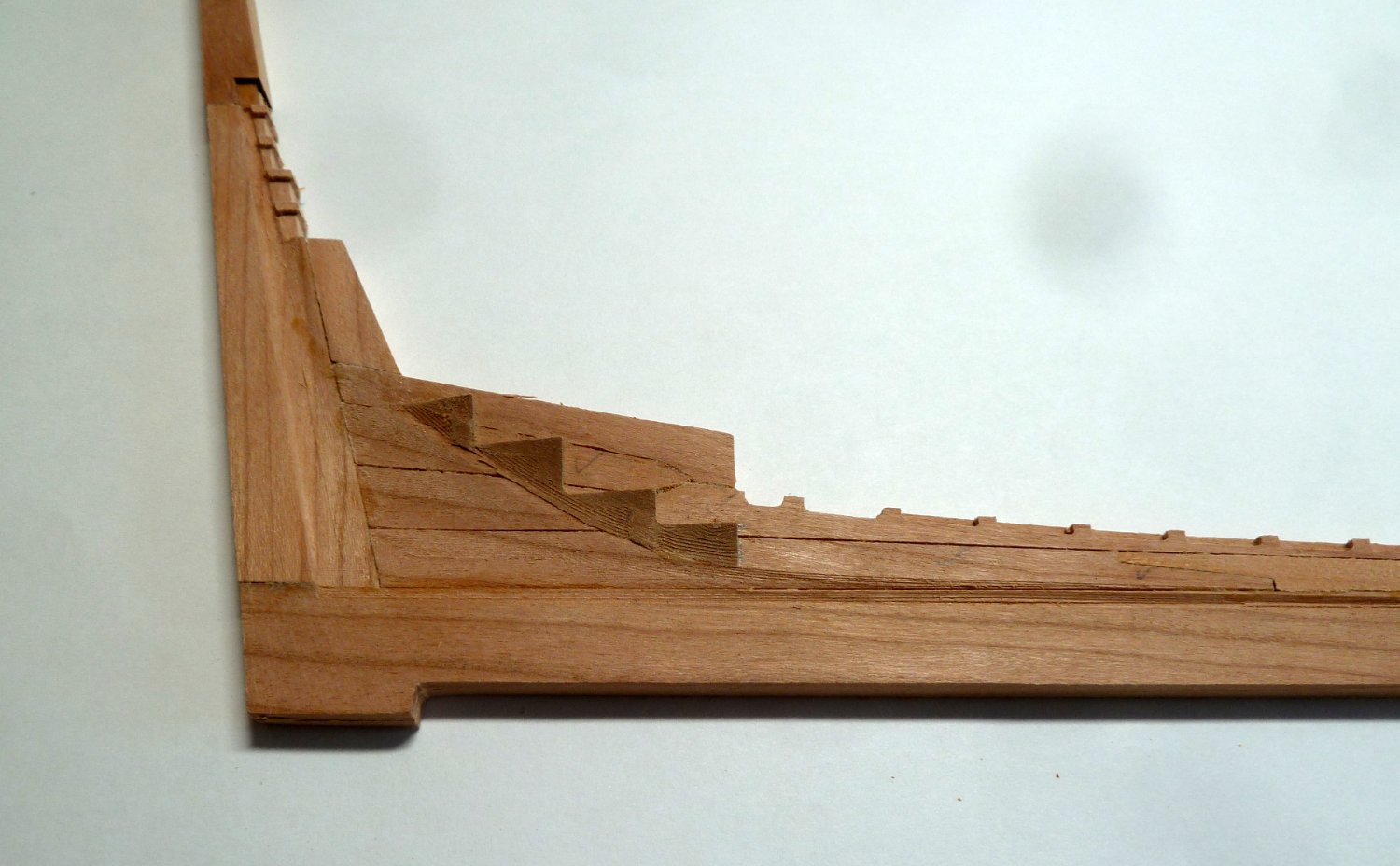
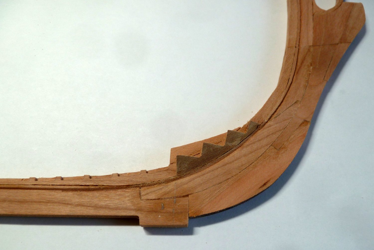
Lots of frames to assemble. It's a bit deceptive as to how the frames are placed on the keel. For double thick frames what appears to be front, and back are labeled a and b. For triple thick frames, they are labeled a, b, and c, where a and c are outer surfaces and b is sandwiched between. The outer sides have fairing lines etched in. This provides a sanding line to both fair up the inside of the framework as well as the outside of the framework. Also, when building the frames, some parts have notches in them. Wondering why the notches are beveled a certain way, it turns out that the purpose is to create a larger gluing surface. The bevels in the notches have no functional use. It took a while to understand that. The picture shows frames 8 and 9 with sanding lines to shape the inner as well as outer part of the frame. I intend to finish sand the interior part of the frame and sand the outer part close and wait till the framework is finished before fine sanding. The single cant frame shows the bevel marks before sanding.
A lot of work but I am awe of the modelers that scratch build these frames admiralty style. Way above my pay grade. So, lots of frames to do. It takes a bunch of frames forward to aft to align the building jig.
- Matt D, HardeeHarHar, bruce d and 3 others
-
6
-
I just worked it out this morning after comparing with the frame location plan.
-
Thanks for tuning in. Lesson learned. The parts in question have been sorted and added per the frame location plan. They are positioned based on measurements taken directly from the plan. If not exact, I think they are close. This build is a first for me so it's learn as you go.


- Ryland Craze, Prowler901 and JeffT
-
3
-
-
-
-
Hi Jeff,
Could you check something for me. When I removed parts from 8A I failed to identify 8A-1 and 8A-2. Once I removed them I noticed that they are different. I have no idea which is which. Two are quite thick and the other two are thin and very fragile. I started a build log. Lots to learn.
-
I started my CAF Granado kit part 1 this weekend and was asked to start a build thread. Overall, Tom did a great job on both the manufacture of the kit and the instructions. This is a first effort for me on building and admiralty style ship model. I worked through step 7 of part 1 and just need to figure out part 8A-1 and 8A-2. I removed them without identifying which is which. I struggled with the CNC Router parts in that after sanding away the rough edges of the parts, the fit of one part to another left some slight gaps. Some needed a bit of filler made from sanding dust and some yellow glue. It did help somewhat. As far as the laser cut parts, very careful removal of the laser burns yielded parts in which once assembled, joined together very nicely with hardly any gaps to speak of. Throughout the build I will have to pay closer attention to laser burn removal and parts fit.
Any and all suggestions or observations will be welcomed.


-
I will be happy to start a build log. I am just about finished with the build, up through step 7. Once that is finished, I will start posting.
- JeffT and HardeeHarHar
-
2
-
Hi Jeff,
I just started my Granado and in response to your December 19th, 2021, post, I am also finding that getting the glue joints perfectly square is quite difficult. I am in awe of the modelers that get these joint perfect. I am hoping the stem pieces are the most difficult and the job will get easier as time goes by. Thanks for doing the build thread. It will be very helpful.
- ChrisLBren, JeffT and mtaylor
-
3
-
-
-
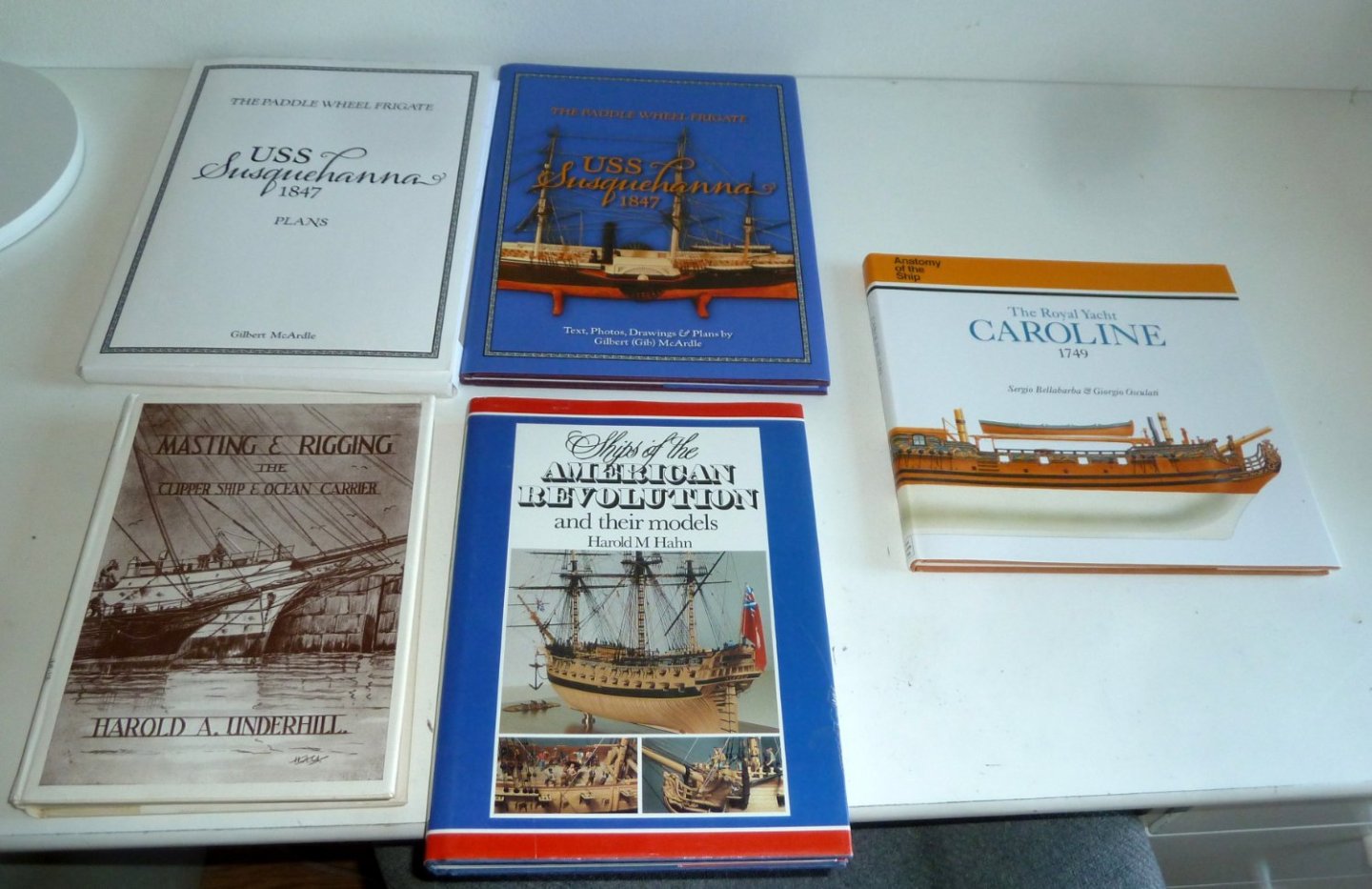
I have the following ship model books and the prices shipped CONUSA:
USS Susquehanna by Gilbert McArdle including plans set, $65
A beautiful Sidewheeler in 1/96 Scale. I was planning on scaling up the 1:48th but no longer.
Masting and Rigging Clipper Ships by Underhill, $45
Ships of the American Revolution by Harold Hahn, $70
Anatomy of the Ship, Royal Caroline 1749, $80
Questions welcome and thanks for looking.


HMS Granado by ir3 - CAF - 1:48 - POF
in - Kit build logs for subjects built from 1501 - 1750
Posted
Thanks for the support, I am beginning to enjoy this.