KeithAug
-
Posts
3,986 -
Joined
-
Last visited
Content Type
Profiles
Forums
Gallery
Events
Everything posted by KeithAug
-
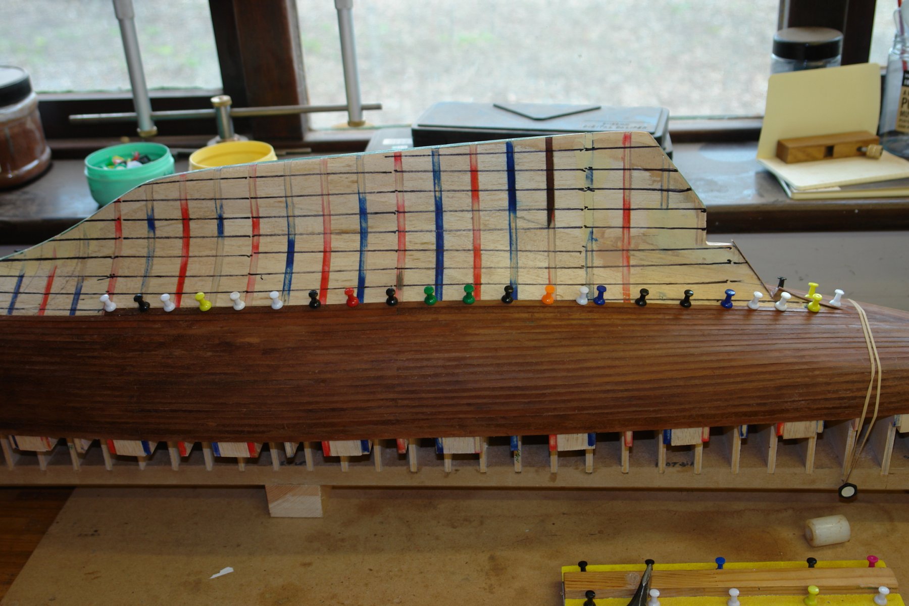
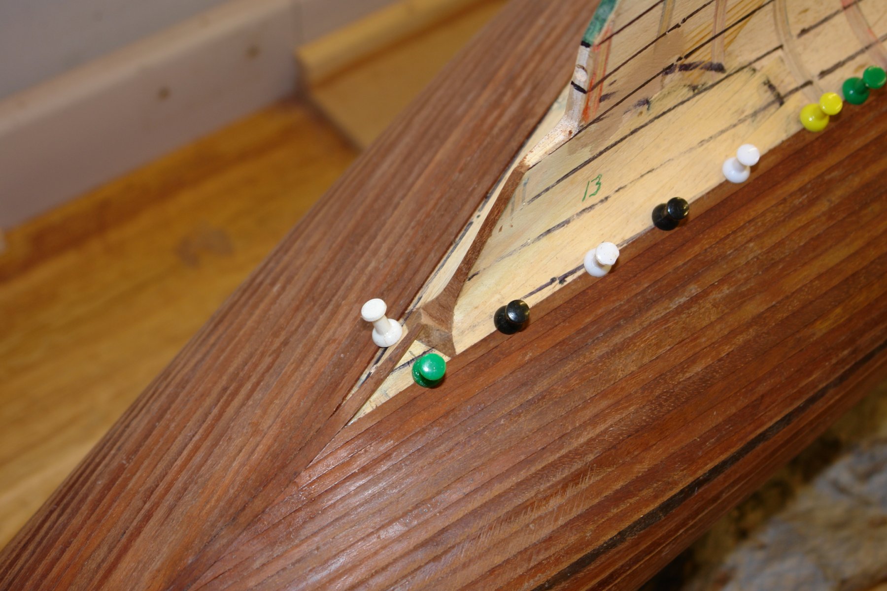
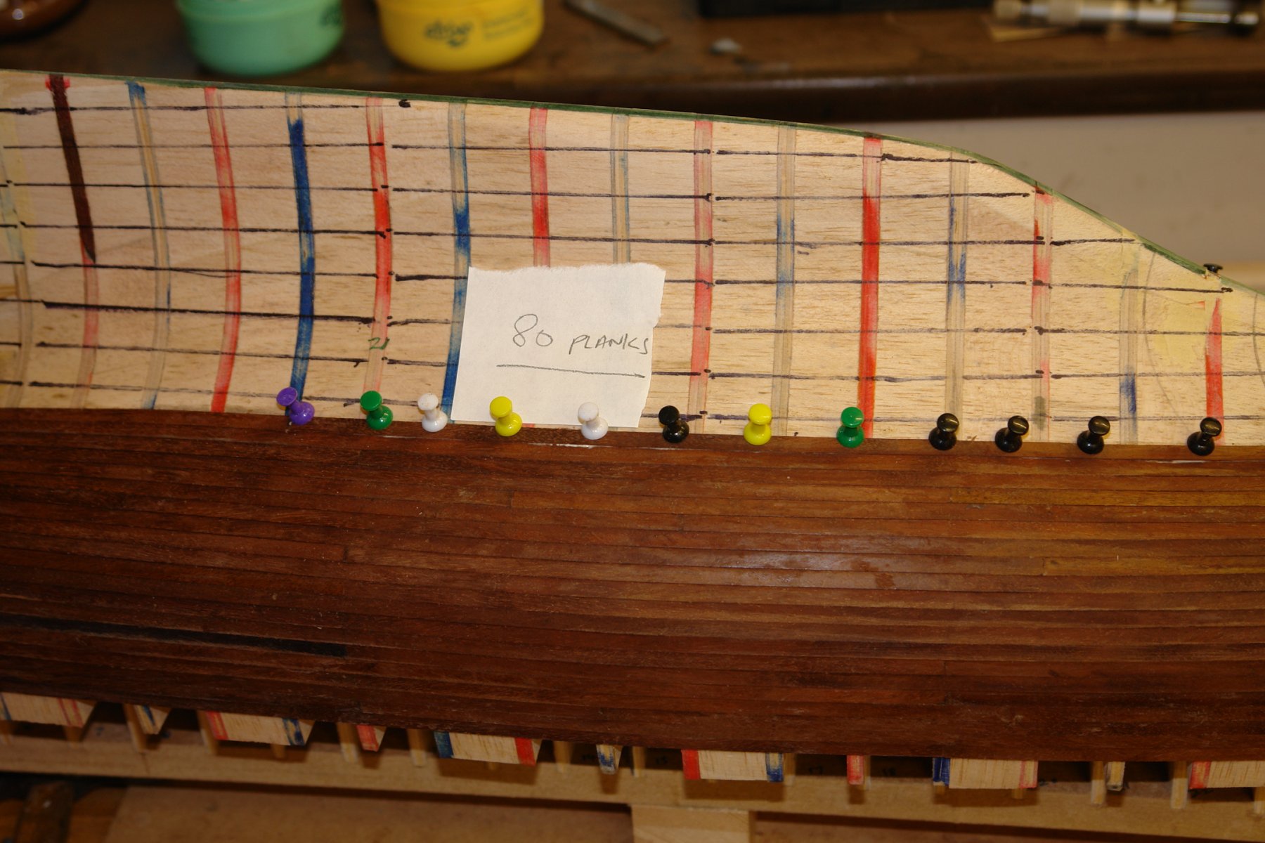
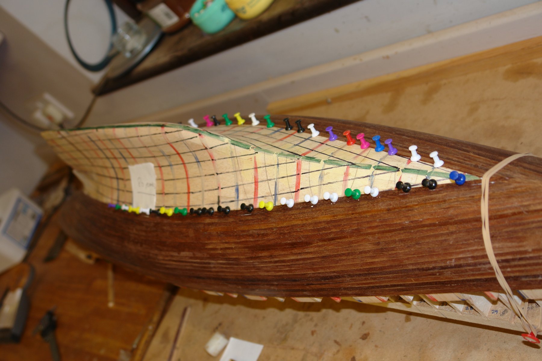
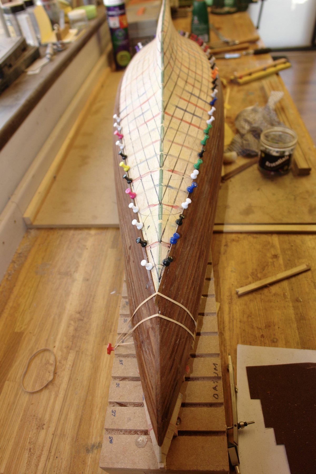
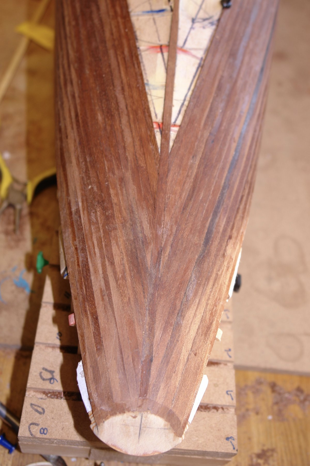
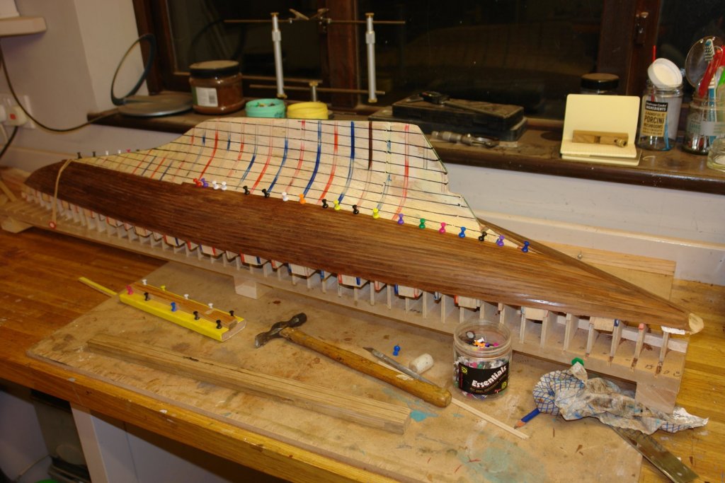
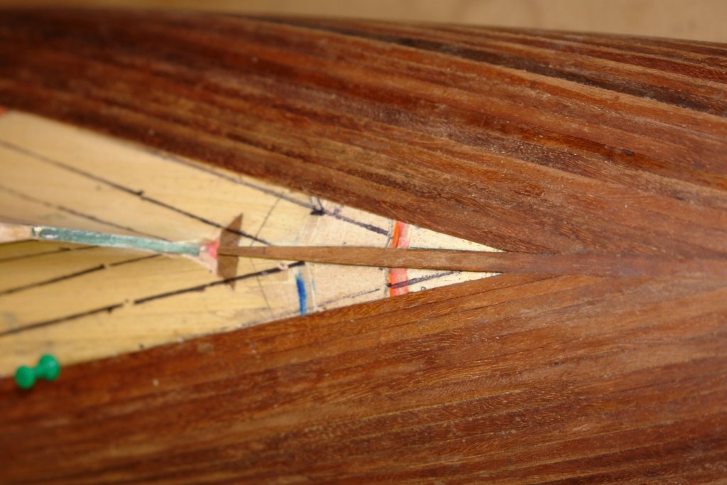
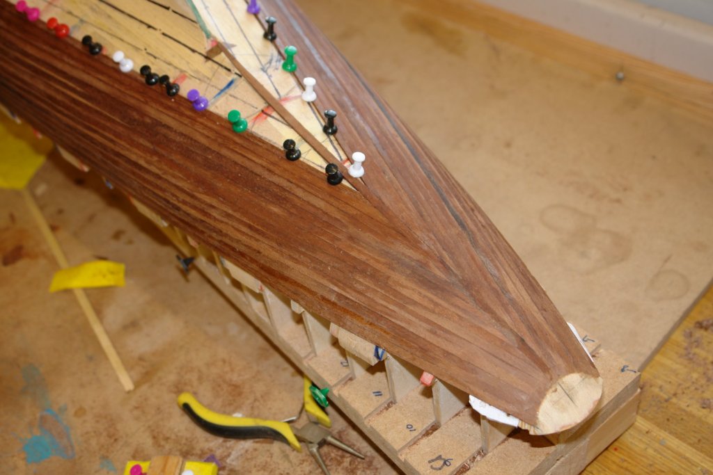
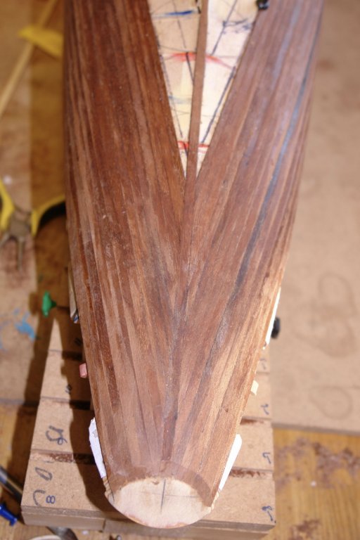
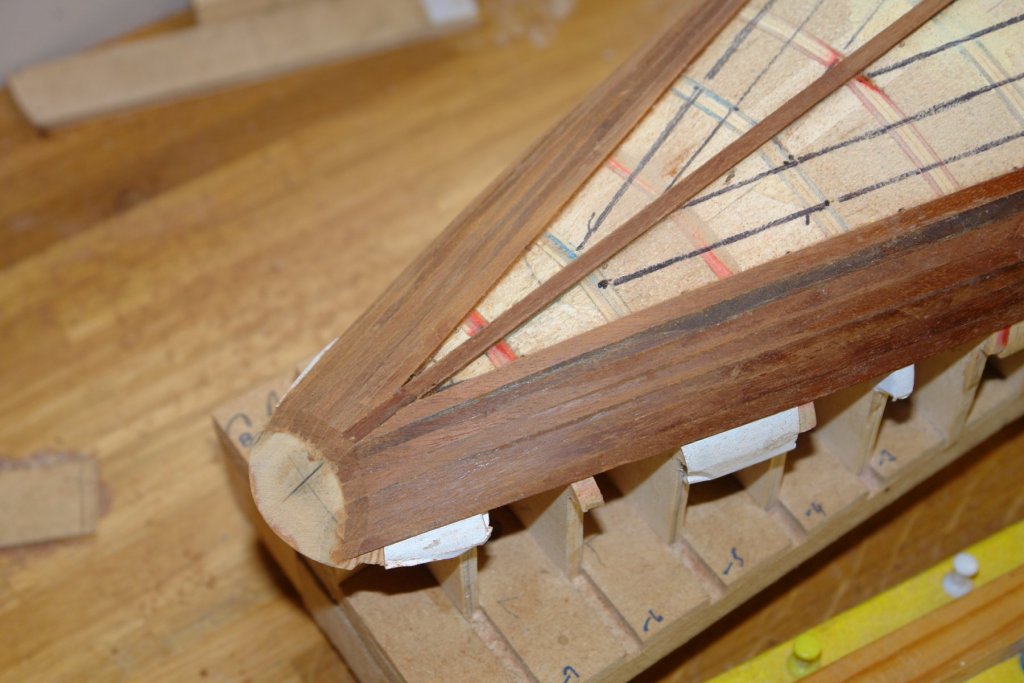
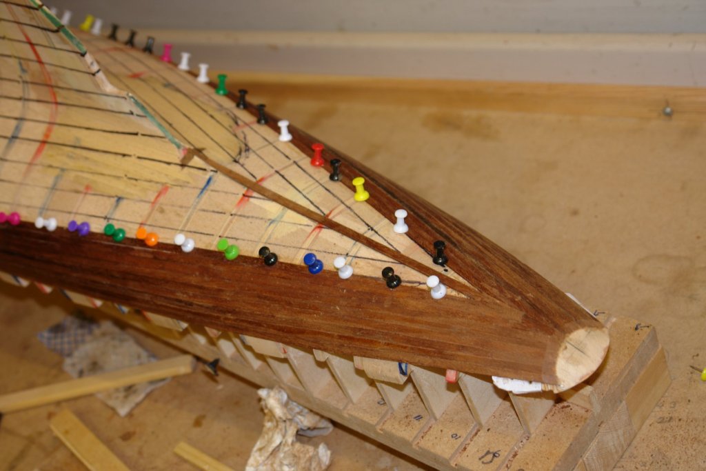
 Planker's Progress 4. It's now day 8 of planking and I am about half way. Most of the time isn't actually work, as glue drying and thinking take their toll on productivity. I continue to work my way up the stern and I am managing the symmetry reasonably well. I have started to cover the rear of the keel in preparation for the next stage of planking. I am still cutting the fine angle at the plank ends with a razor saw but increasingly it is becoming a compound angle with the saw cut currently deviating by about 15 degrees from vertical. At the bow I am starting to move on to the flatter section and in consequence the port and starboard planks are overlapping along the line of the keel. As I complete a plank I sand the end flush from the opposite side and then notch it out to take the next plank ( a bit like interlaced fingers). 80 planks are now in place. Over the next couple of days those awkward hull / keel intersection planks will go on (hopefully).
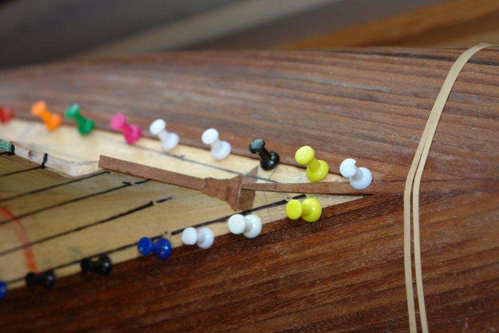


-
Funny you should say that - I just sat down for a cup of tea and as I mused on todays progress I thought "I have spent most of the day wondering how I was going to do the next bit. Welcome to the indecisiveness club!
-
Ah I see, only 3 years to go. Tweezers - I bought a set, my son bought a set - the manufacturer probably never knew why his sales took off.
-
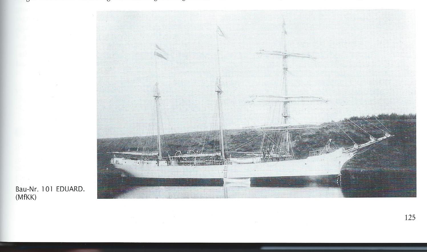
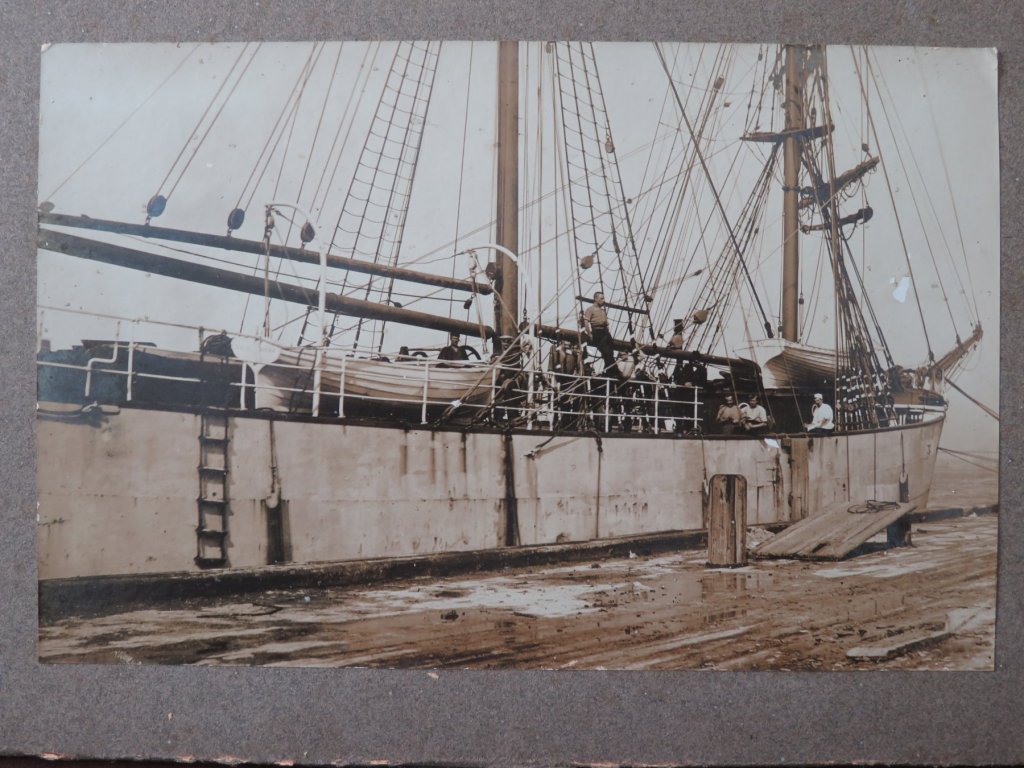
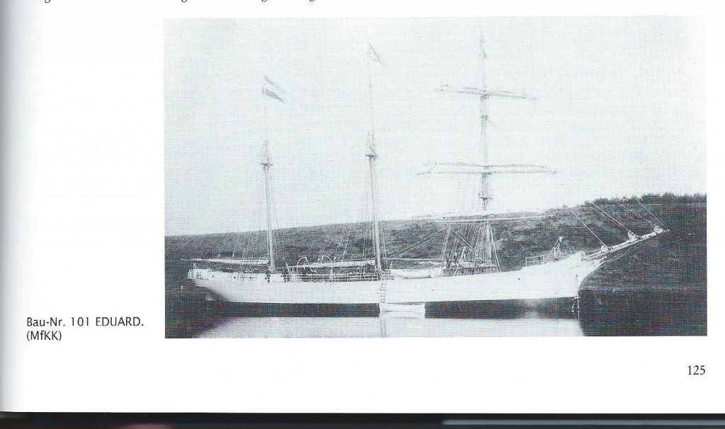
Eberhard. Yes I will need to manage the "flow" of the planks quite well particularly at the hull/keel intersection. The mahogany I am using beautiful close grained stuff but being 100 years old it is somewhat brittle and hence does not like challenging shapes. Thank you for your earlier help with SV Eduard. We obtained a copy of the book you recommended and also turned up an image from the family photo library. My wife's grandfathers Masters Certificate specifically states he was licensed as a Master of fore and aft rigged vessels. She was an elegant looking vessel - at least until UC-70 got her.
-
Paul. She is looking good for a 4 year old. I once took 20 years to complete a model so you have a way to go until you can claim she is a veteran build. 12 deg C in my workshop for the last week, I assume you are benefiting from the same mild conditions? P.S - we must have all bought those nice cheap tweezers.
-
Thanks Pat. Im hoping it will look much better when sanded. I need the finish to be very smooth.
-
Amazing work - almost impossible to believe.
- 1,035 replies
-
- 8
-

-
- royal katherine
- ship of the line
- (and 1 more)
-
Doing is better than thinking when the brain matter reaches a certain age.
-
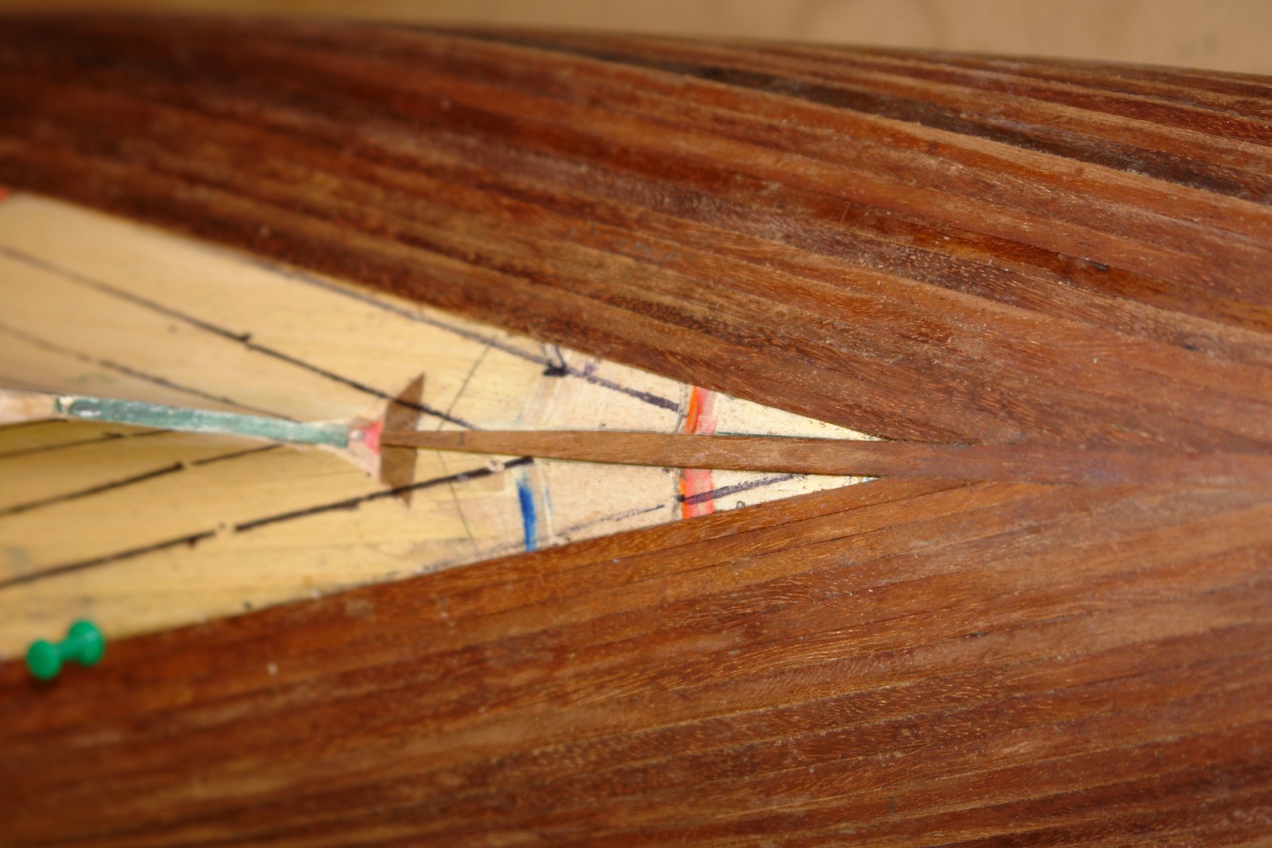
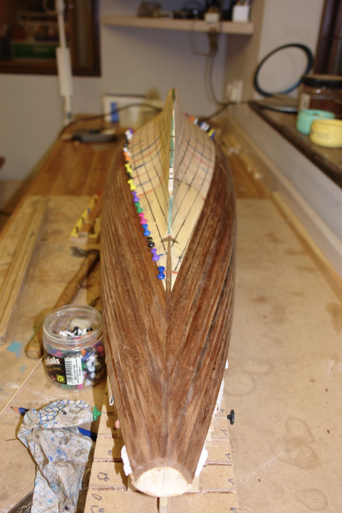
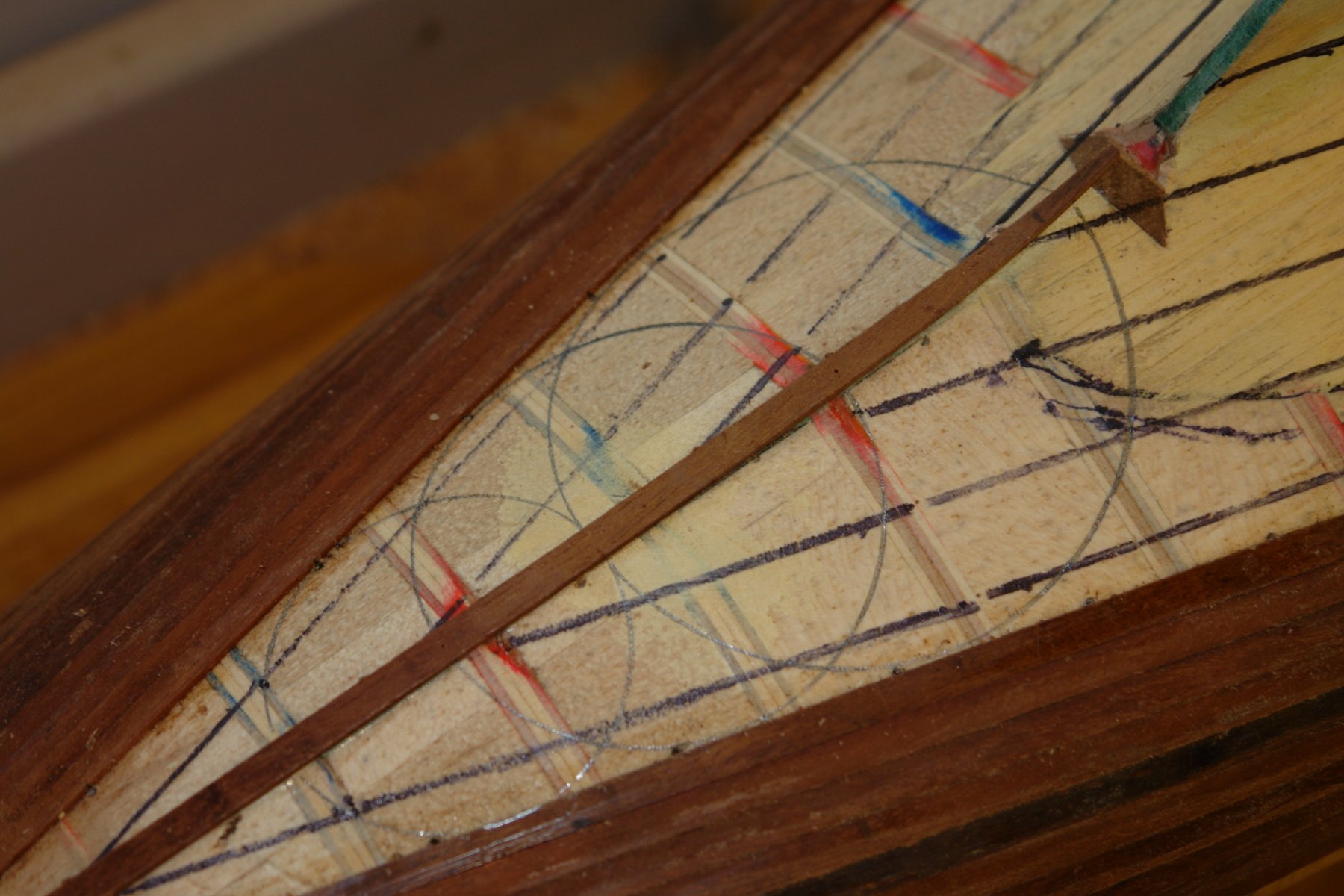
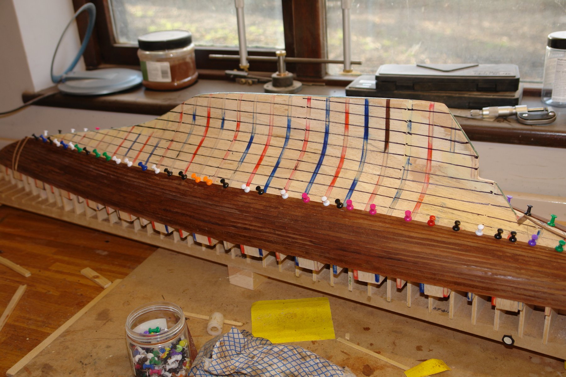
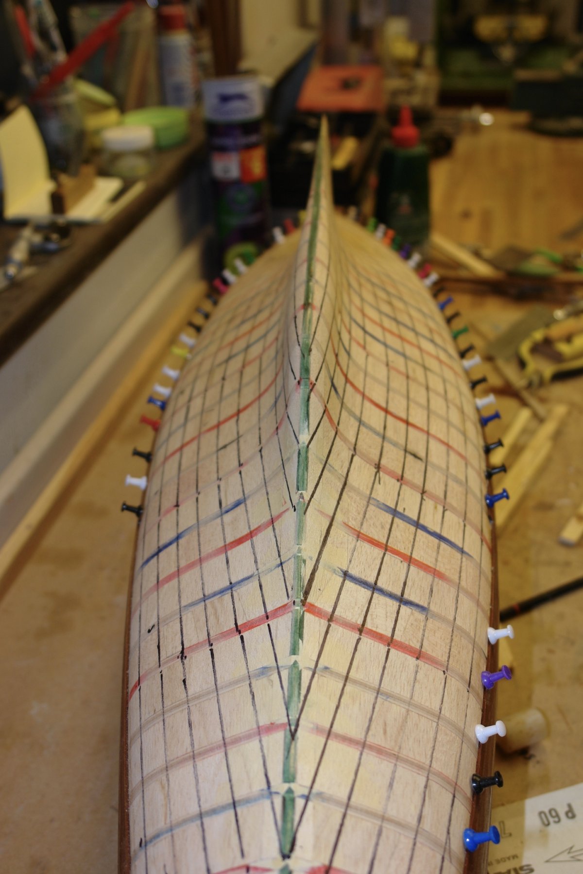
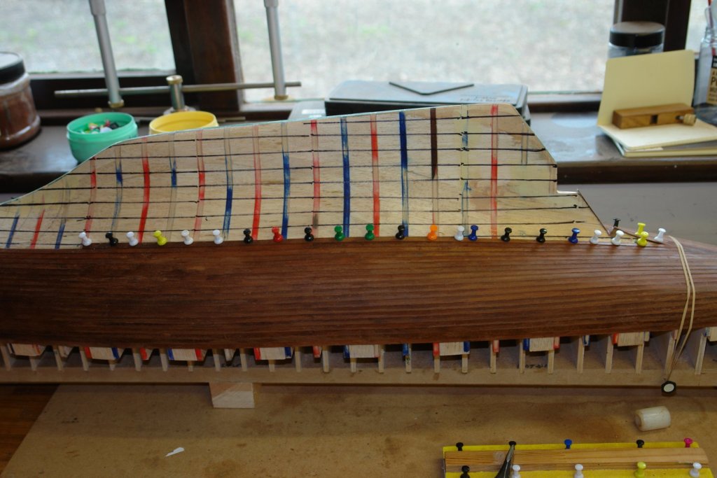
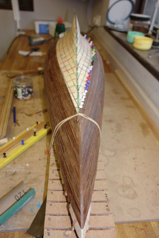
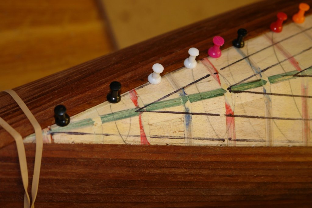
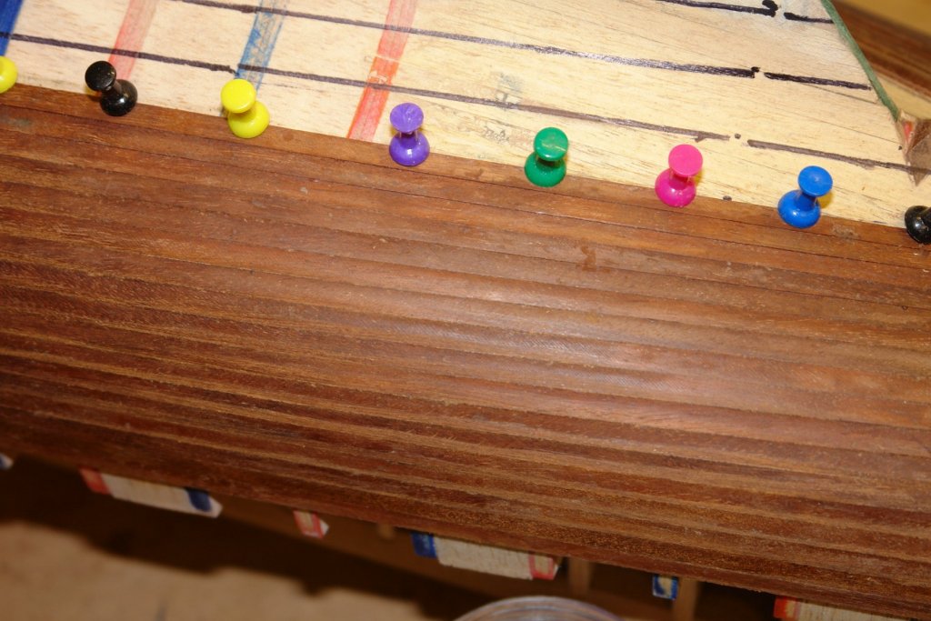
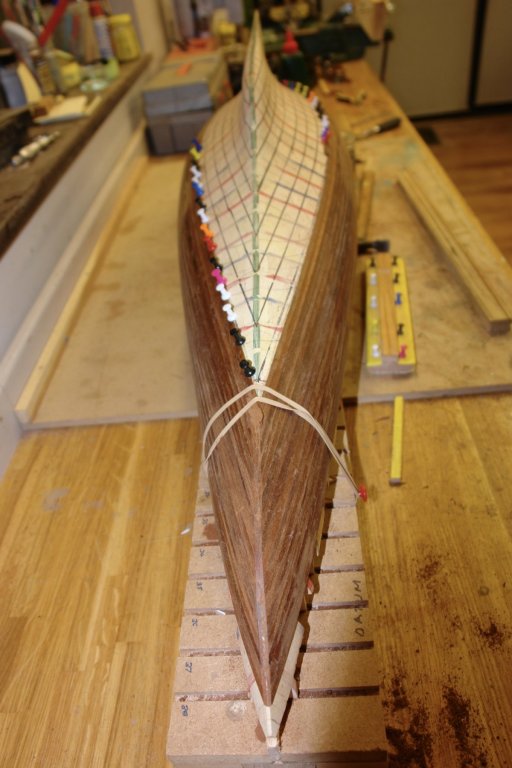
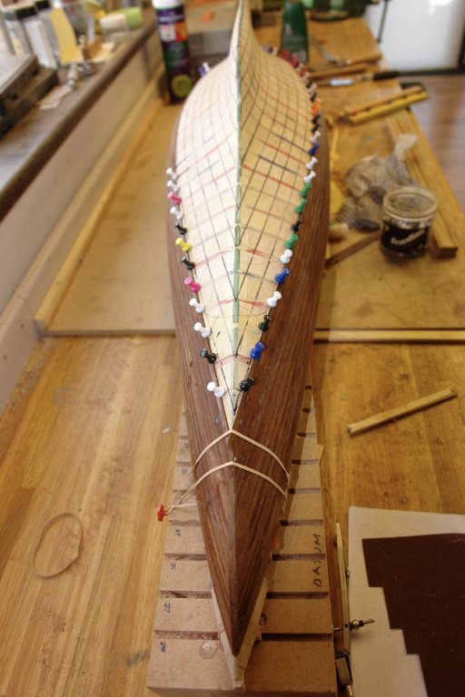
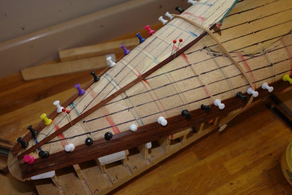
Planker's Progress 3. Michael / Pat - thank you for the feedback. Another 2 days gone by so that makes it 6 days since I started. I am still progressing with the easier planks i.e. those where the curvature is relatively gentle. I don't need to do any heat or steam bending at this stage. The most awkward aspect is the twist that occurs as the planks turn from the more vertical side on to the more horizontal stern. You can see the twisting region below the 7 pins towards the right hand side of the photograph below. The stern planks are progressing quite neatly. I am taking care to eliminate any potential gaps between the planks. I also used circles on the bow to ensure symmetry. It is more obvious in the following photo how the circles assist with this task. The flat keel line will be covered by a keel plank before sanding to a "sharp" line. Finally a side view of a section of planking - pleasingly gap free.

-
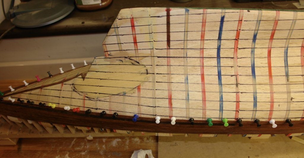
Plankers progress 2. Days 3 and 4 were reasonably productive. To keep things symmetrical I dew a series of circles on the underside of the stern. As I planked I checked that the plank intersection with the circles were mirror images on each side. Slight adjustments were made by sanding the appropriate plank edges as part of the chamfering process. I I also did the circle trick on the underside of the bow. Progress looks better than it actually is - I estimate I am a little under 1/3 of the way through. My circles on the stern however are disappearing at a pleasing rate. The side view gives a better impression of progress. The stern view shows that I am not following the previously drawn (parallel to deck) lines. I am finding that my guess that I need to taper the planks at the stern by half their width is proving to be about right. About one plank in 5 is going in as a parallel plank. At the bow I need less taper and every other plank seems to want tho be parallel. I'm expecting the next few days to see some disruption. I have been left "Home Alone" to look after the dog. Progress may be slow.


-
Pat, I'm not sure that it is the grain direction. As I am using salvaged mahogany it could just be that this was on the surface and over the years had become encrusted in grime and is contrasted by the freshly cut planks on either side. It is in a position that I was planning to paint so I think it will be alright.
-
I am calling the next series of posts "The Plankers Progress" - Chaucer is probably turning in his grave. I am going to try to post this as I progress to give an idea of my (slow) progress. Here goes with the first 2 days of achievement:- Before starting the planking I gave the hull a coat of one part PVA one part water. I did this to seal the balsa and give a better foundation for gluing the planks. Once dry i gave the hull a light sanding to remove the raised nap Before starting I estimated the number of planks I needed. This turned out to be a bit disconcerting - circa 150 nearly all of which need to be shaped. I thought of the guy estimating the bricks for the great wall of China and decided that my task wasn't that bad after all. I started at the deck level with 2 parallel planks and then it was into tapering all 4 planks in each layer. The bulwark planks will be added once the hull planking is complete. At the stern I attached a "keel" plank as an abutment for the hull planks as they curve and twist towards the stern. `The slight curve at the rudder end of the keel plank was formed after soaking it in boiling waster for a couple of minutes. Because of the narrowness of the stern it didn't take many planks before the I was cutting the plank ends at a fine angle to abut the keel plank. The angle was established by laying the plank on the hull and marking the line with a fine razor saw. Where necessary the angle was corrected with a sanding stick. The plank transition on to the transom was roughly sanded - to be finished once the hull planking is complete. I also did a bit of light sanding of the hull planks to test that they were going to sand flush. I'm not sure why one plank is so dark - hope it will not be a problem later. 2 days progress looks small but inevitably progress was punctuated by drying interludes as each layer of planks dried - allowing the holding pins to be removed. Still a long way to go:-

-
At least the rudder is going to be simple to make.
-
Gary - thank you for your kind comments. You too may ultimately possess tools of this quality if you save up your pocket money. Michael, Pat, Vossiewolf - thank you for dropping in again.
-
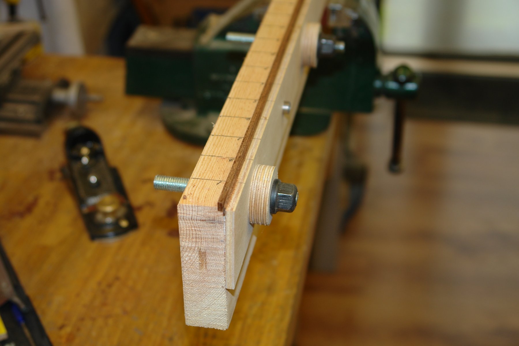
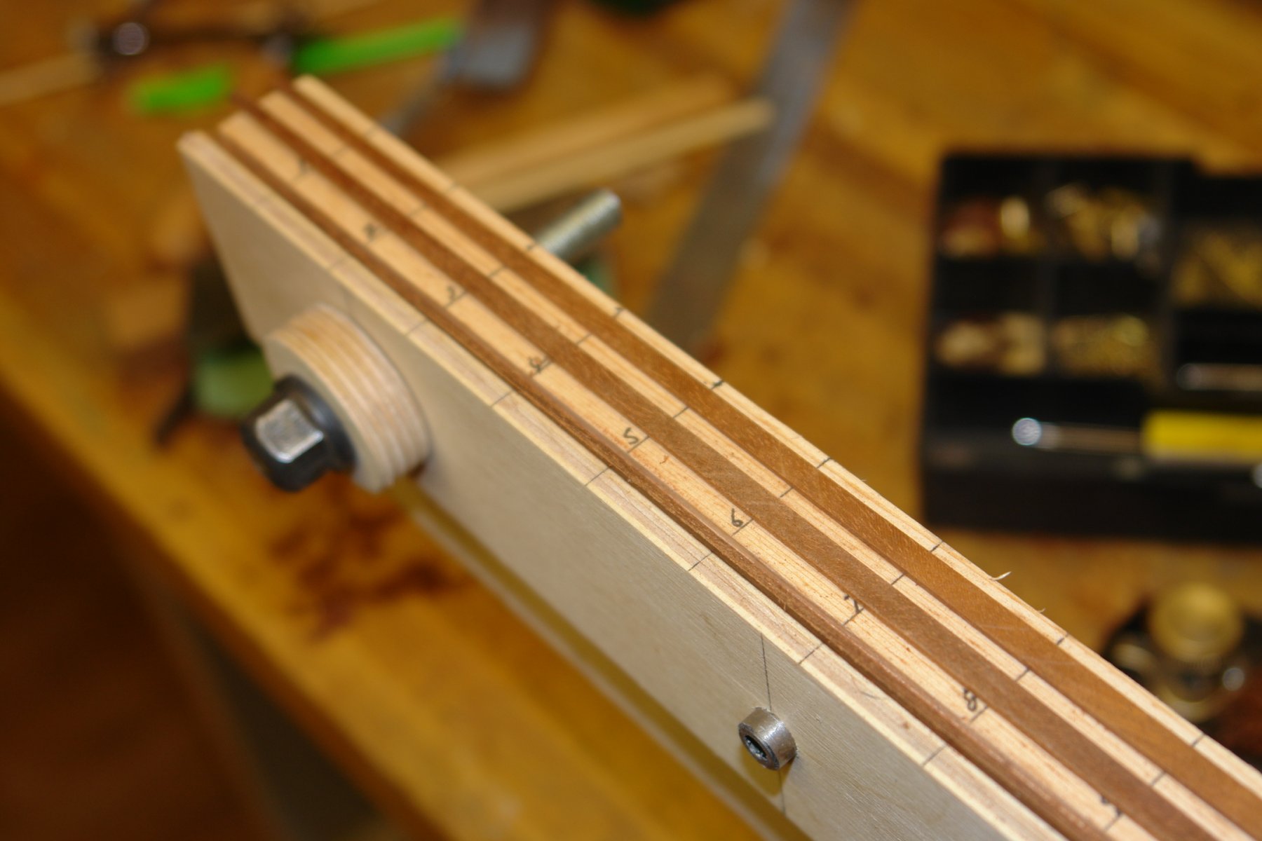
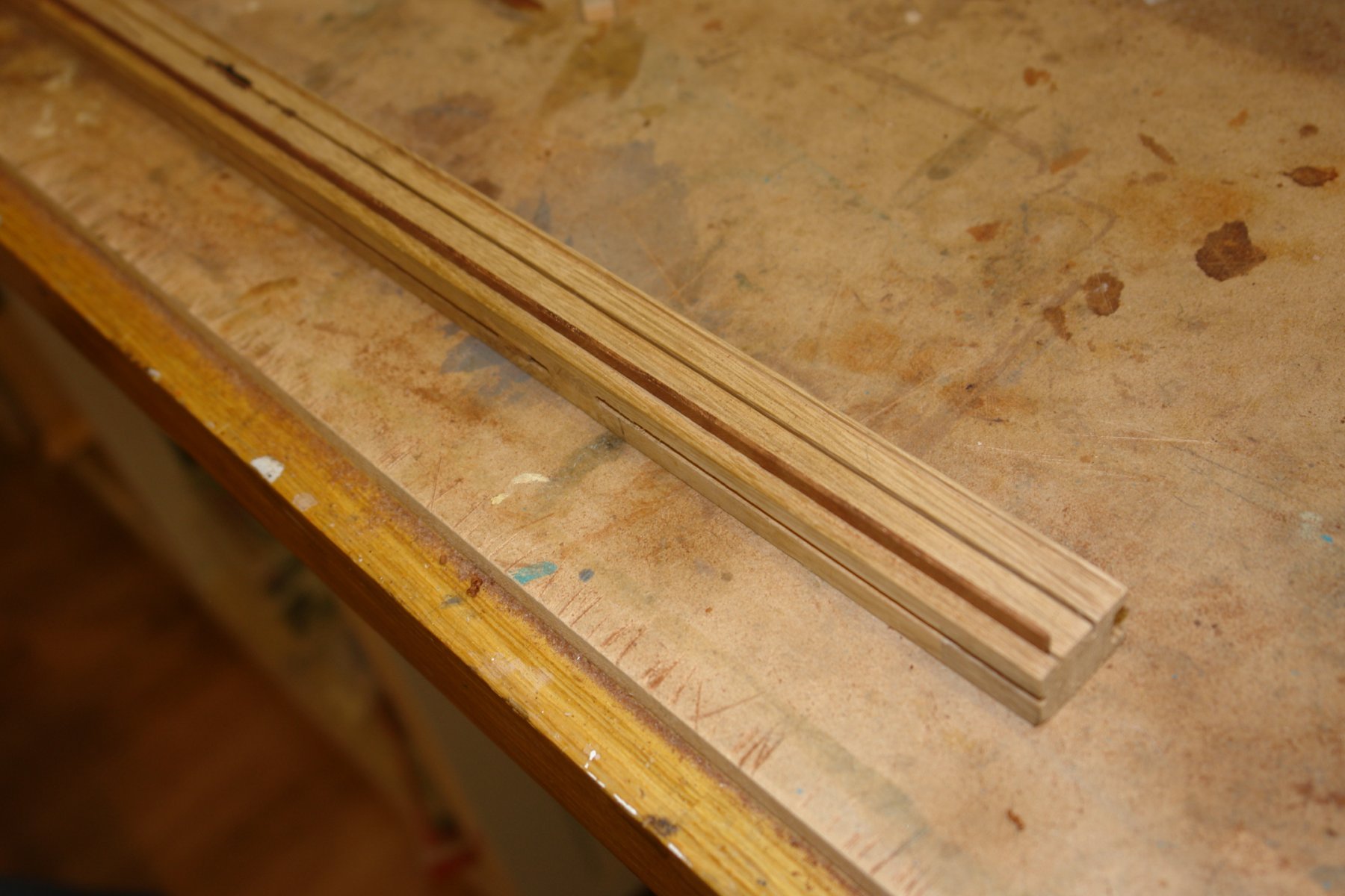
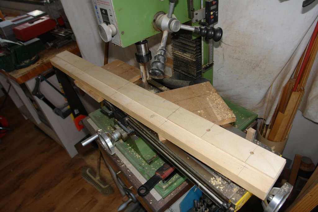
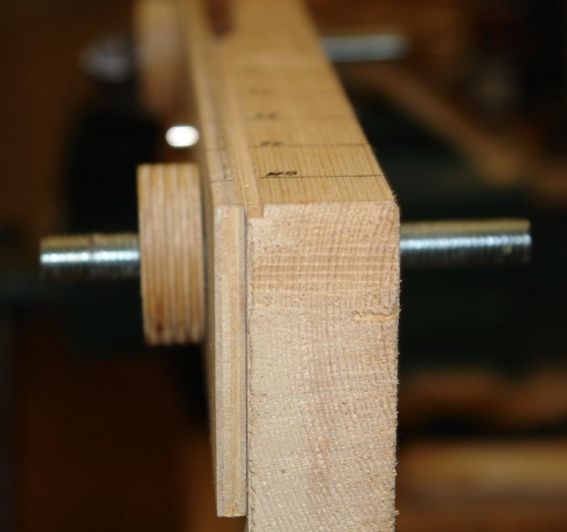
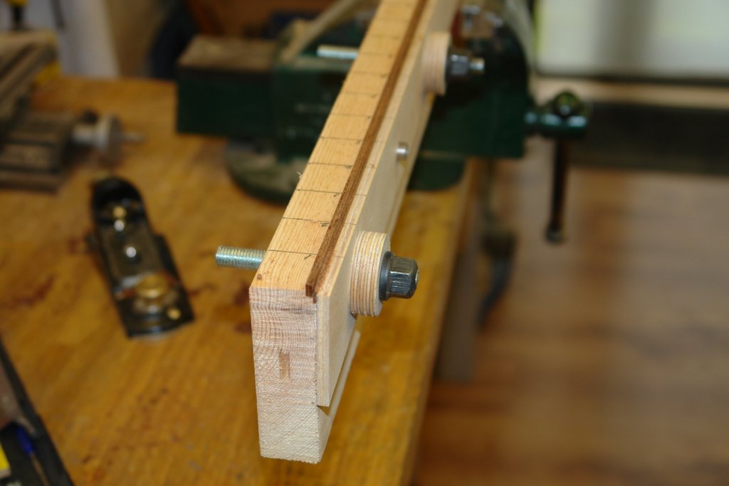
In preparation for planking I thought I needed a clamp for holding planks while tapering the edges. In the past I have bodged something at the time with varying degrees of success. This time I thought that given the number of planks needed I would construct something little better. The clamp was made from a pine plank of 40" x 3.5" x 1" and a piece of ply 40" x 2" x .250". Both pieces were temporarily stuck together and 7 holes were drilled - 5 holes to take M10 clamping bolts and 2 holes to take 10mm alignment spigots. The top edge of the pine had recesses routed on either edge - one recess was 0.1" by 0.1" to take a pair of .055" x 0.225" planks and the other recess was 0.1" x .05" to take a single 0.55' x 0.225" plank. The clamping bolts and spigots were glued into the pine with epoxy and washers were made from .375" ply. The top surface of the pine is marked in inch divisions to assist when planing different tapers. There clamping nuts are temporary pending a visit to the local hardware store to get some M10 wing nuts. The ply has a sacrificial inner edge glued in place and this is cut to a taper as a guide for the planing of the hull planks. Below are the first 2 tapered hull planks laid temporarily on top of the pine plank. You can see the taper guide plank still in place on the moveable ply jaw. I also slotted out a piece of oak with varying thickness slots to hold the planks while chamfering the edges. A plank is inserted in the nearest slot for chamfering. Chamfering is of course necessary to ensure gaps are eliminated on tight hull curvatures.


-
HMCSS Victoria 1855 by BANYAN - 1:72
KeithAug replied to BANYAN's topic in - Build logs for subjects built 1851 - 1900
Pat - cute little winches - very nicely made.- 1,013 replies
-
- 5
-
-
- gun dispatch vessel
- victoria
- (and 2 more)
-
Very nice work.
-
Hi Paul. The advantage of this approach is that you eventually end up with twice as much material as you started with. You will be able to sell on the spare and plough the surplus into a workshop central heating system.
-
Pat All covered here Post 46 and later (although earlier posts are also interesting):-
-
I tend to save my Byrnes TCT blades for jobs where I need better finishes or want to reduce waste (because of reduced kerf). Where I'm not worried about waste i use these (Amazon):- Needs a bore spacer but avoids complication of larger blade mods described by Kurt.

-
I use slitting saw blades extensively preferring .031" (0.8mm) wide for slitting hull planking. The only problem I ever get is when I try to push a worm blade beyond its useful life. Fitting a new blade usually transforms the situation.