KeithAug
-
Posts
3,867 -
Joined
-
Last visited
Content Type
Profiles
Forums
Gallery
Events
Everything posted by KeithAug
-
 Kevin, I think the MDF will give you much greater rigidity. Have you considered 1/8" ply and rejected it? The build is looking good.
 -
Neil - a bit of a long shot - Did you serve on the Blue Funnel Line and if so did you come across Captain Michael Tomlinson?
-
Neil Deans marine have a good selection of cargo vessels. You may find something here. http://deansmarine.co.uk/shop/index.php/cPath/10_20
-
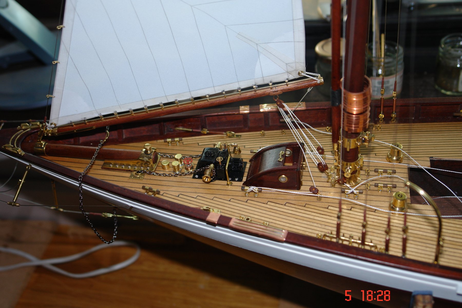
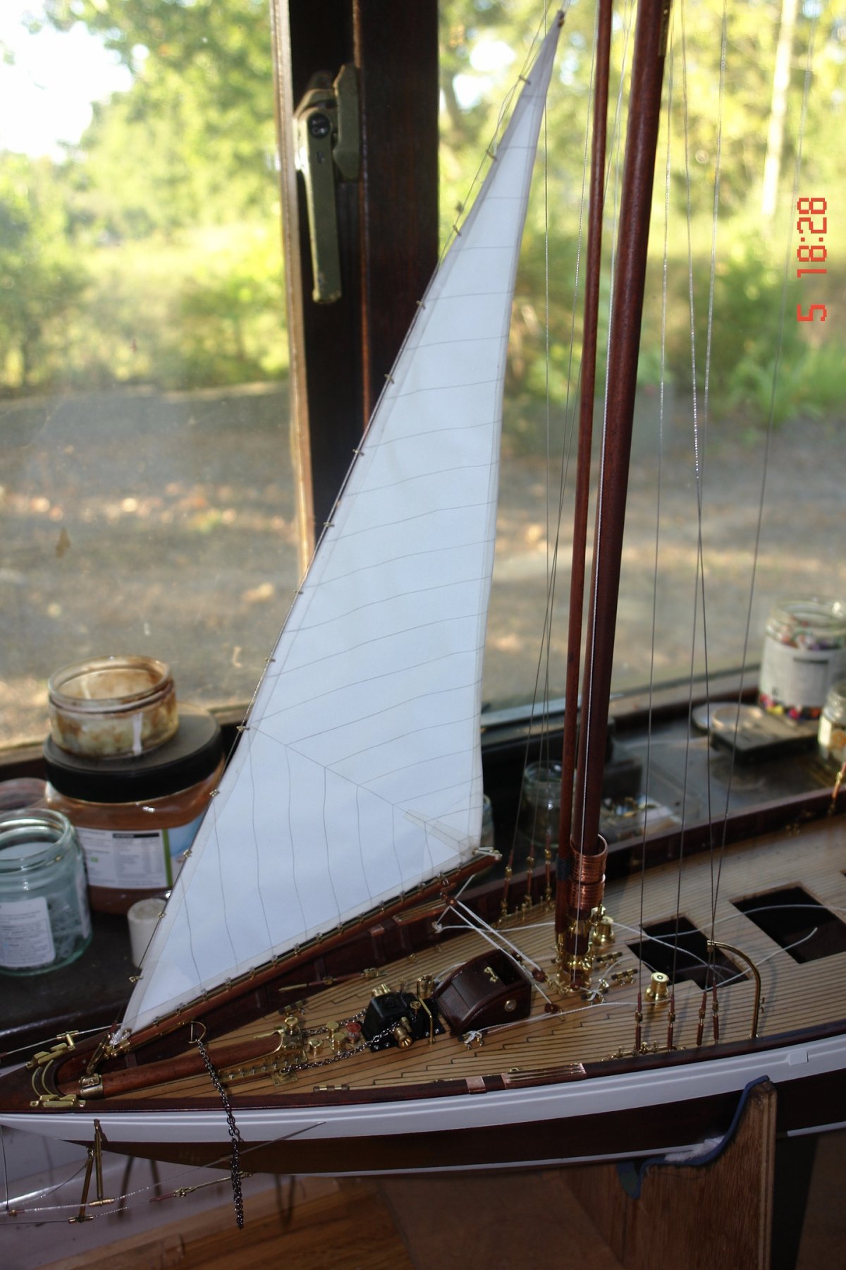
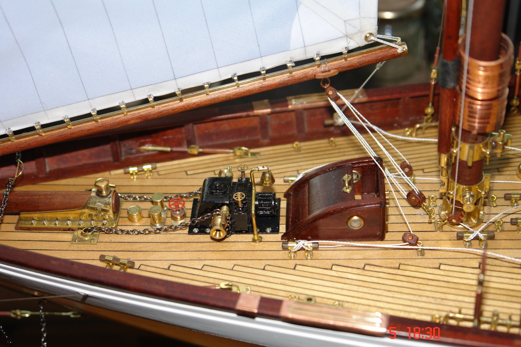
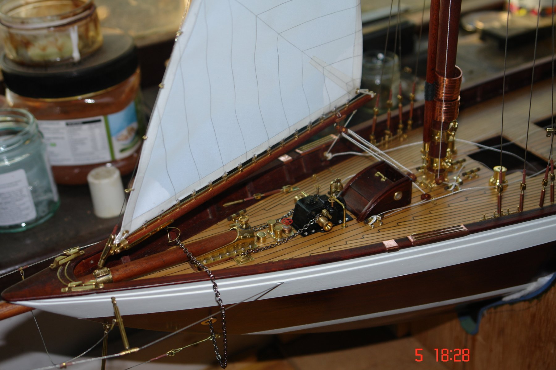
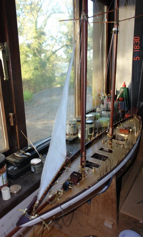
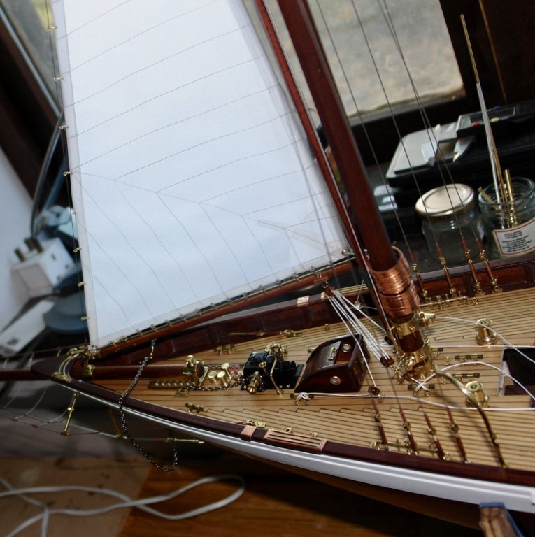
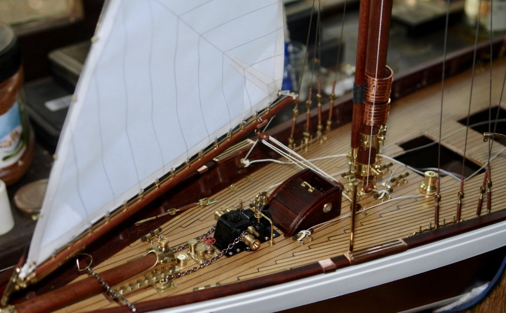
Thank you Kees and Nils. I spent a bit of time hoisting the staysail. I think I may have to invest in some rigging tools. Suggestions would be most welcome. I want to set the sails close hauled on a port tack. The natural action of the sheets and blocks is to hold the booms aligned fore and aft on the centre line. To hold the booms to starboard I need to rig preventers which is a bit unusual for this point of sail. I will console myself by assuming the helmsman has has too much grog and the crew as a result are nervous about the possibility of an unintended pirouette. This is not as far fetched as it sounds, a very long night in the Wide Mouthed Frog and a next day hangover while plugging the tide through the Sound of Luing produced just such an event. Setting the sail was a slow process, primarily because I had to make a few more blocks as well as finishing off some of the foredeck detail. Here are a few photos:-


- 882 replies
-
- 14
-

-
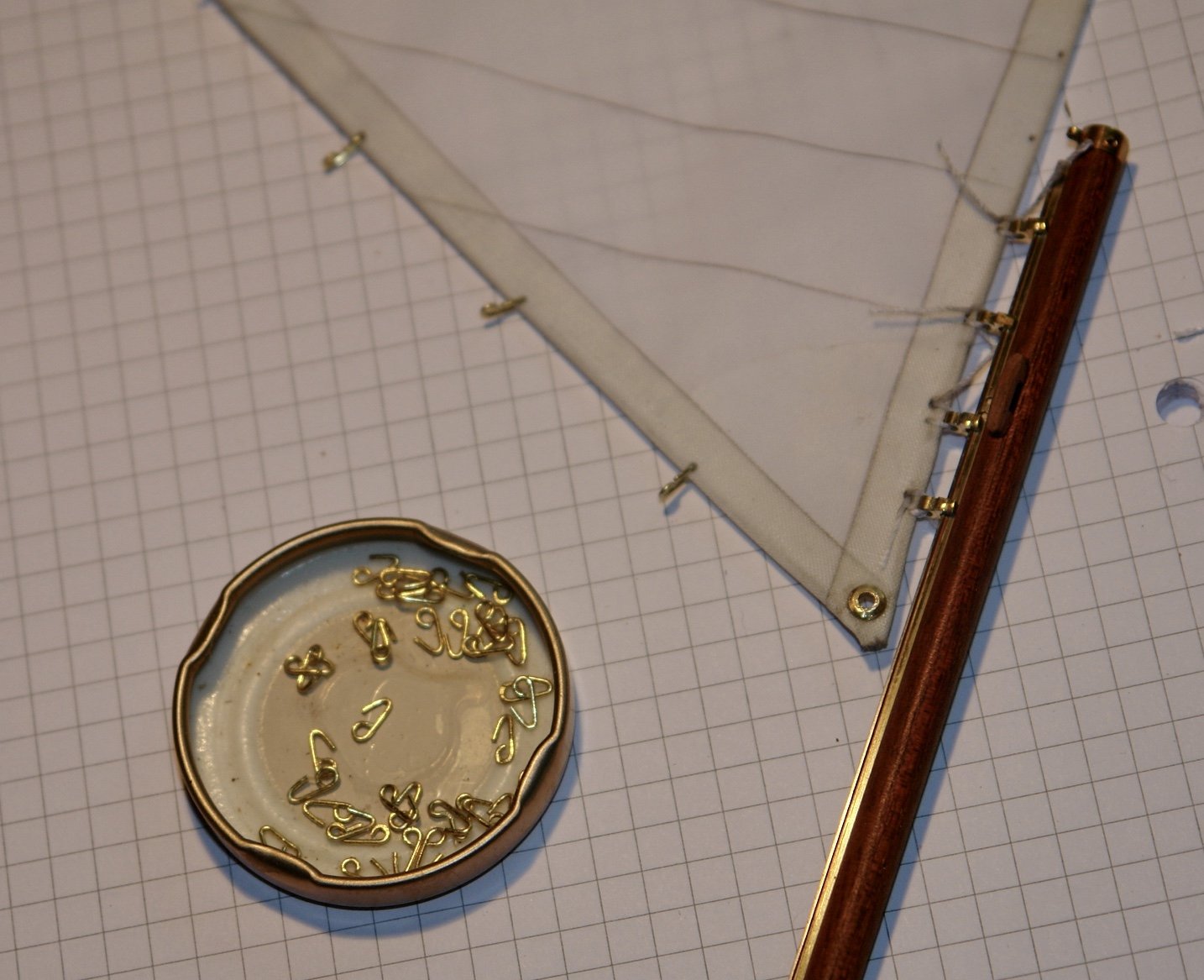
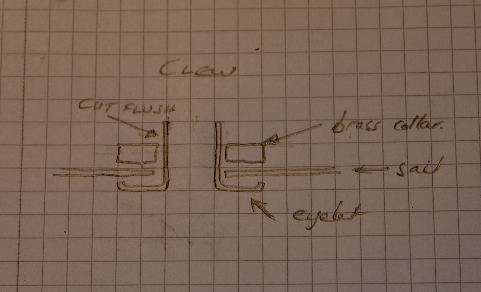
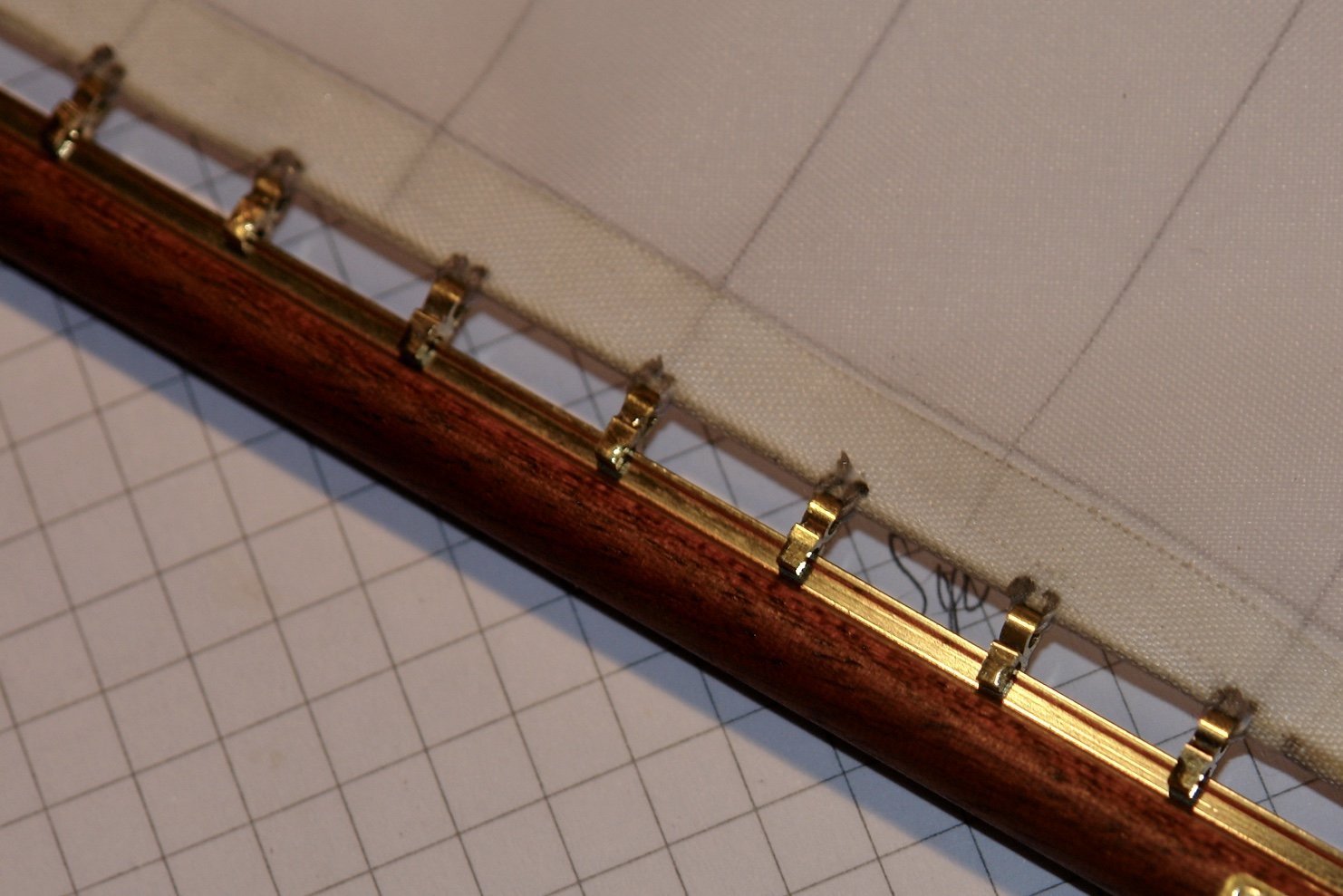
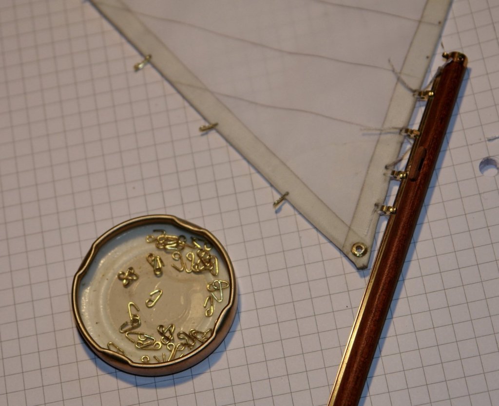
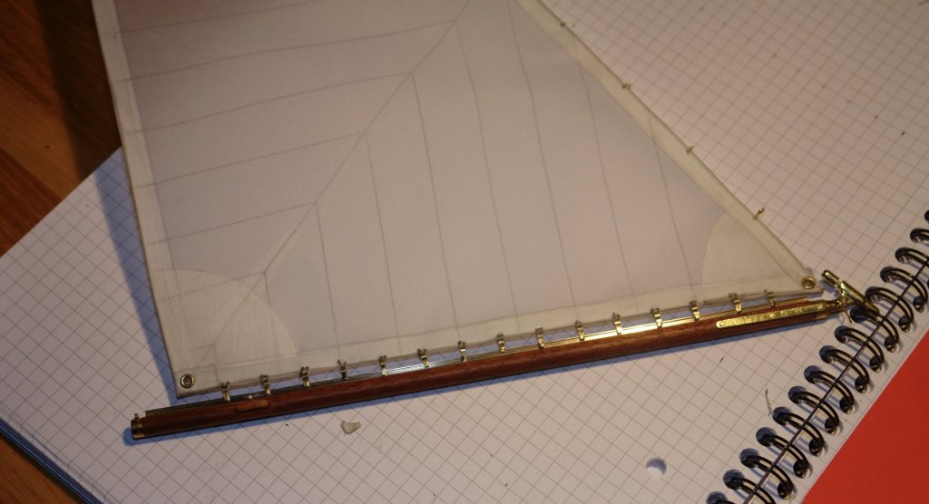
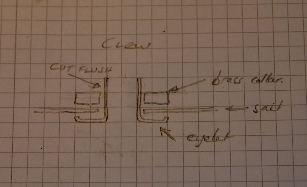
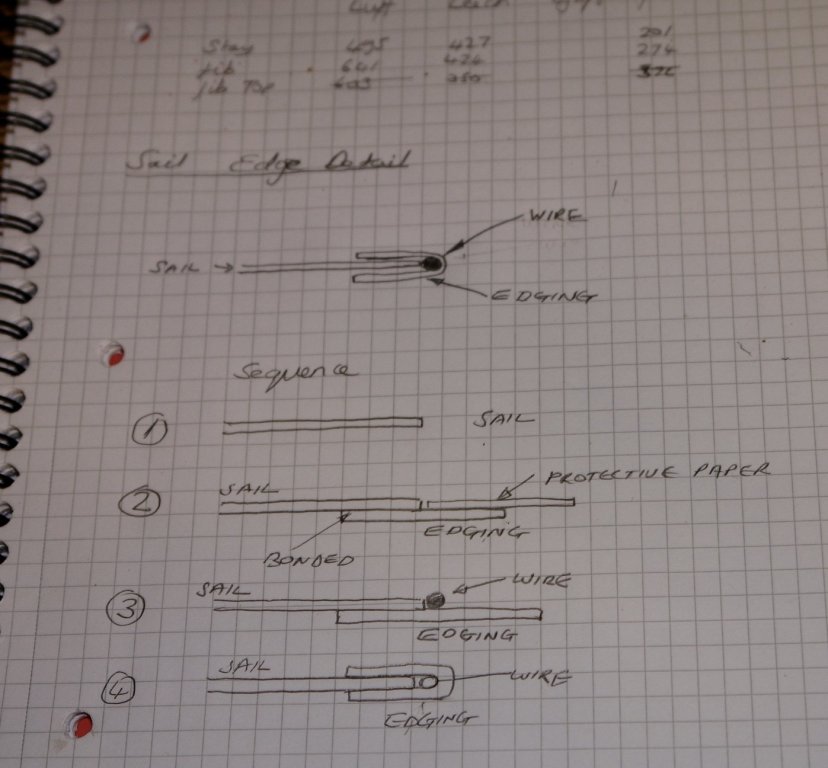
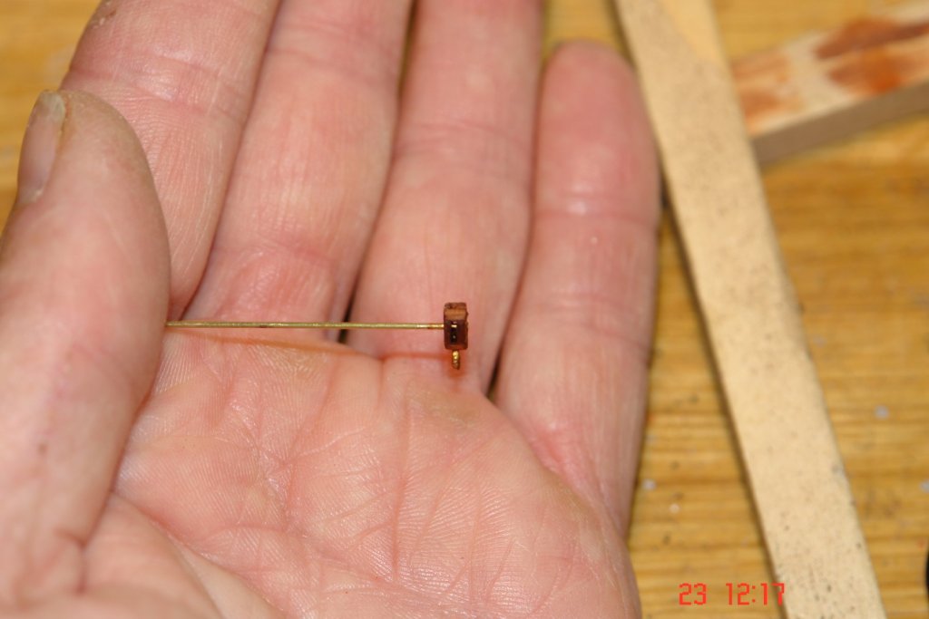
A small update. I decided to try insetting separate wires into each edge of the sail rather than making a triangular hoop as previously described. This worked better as I could get the wires more taught and hence straighter. The penalty was lack of edge reinforcement at the corners. A small penalty which I don't think will matter. I decided to complete the staysail to test how it would look. Rings were inserted (tack head and clew). They were made from eyelet washers but rather than splay the end I put a machined brass ring on the shank as per sketch and glued it with CA. I spent a few hours last night sat in my chair making hanks out of .015" brass wire. These were inserted through the sail (behind the edge wire) and crimped in place. I then started sewing the sliders along the foot of the sail. When I went to school boys did woodwork and metalwork and girls did needlework and cooking. I fear I may have missed an important part of my education. I did a test after attaching 4 to make sure they would slide on. Once attached the sliders were eased on to the staysail boom. All went well. A close up to show the sliders / attachment stitching.


- 882 replies
-
- 12
-
-
Hellmut, An interesting description of your workshop. I hope you get many years of pleasure out of it and that over the years your children come to value what you make.
-
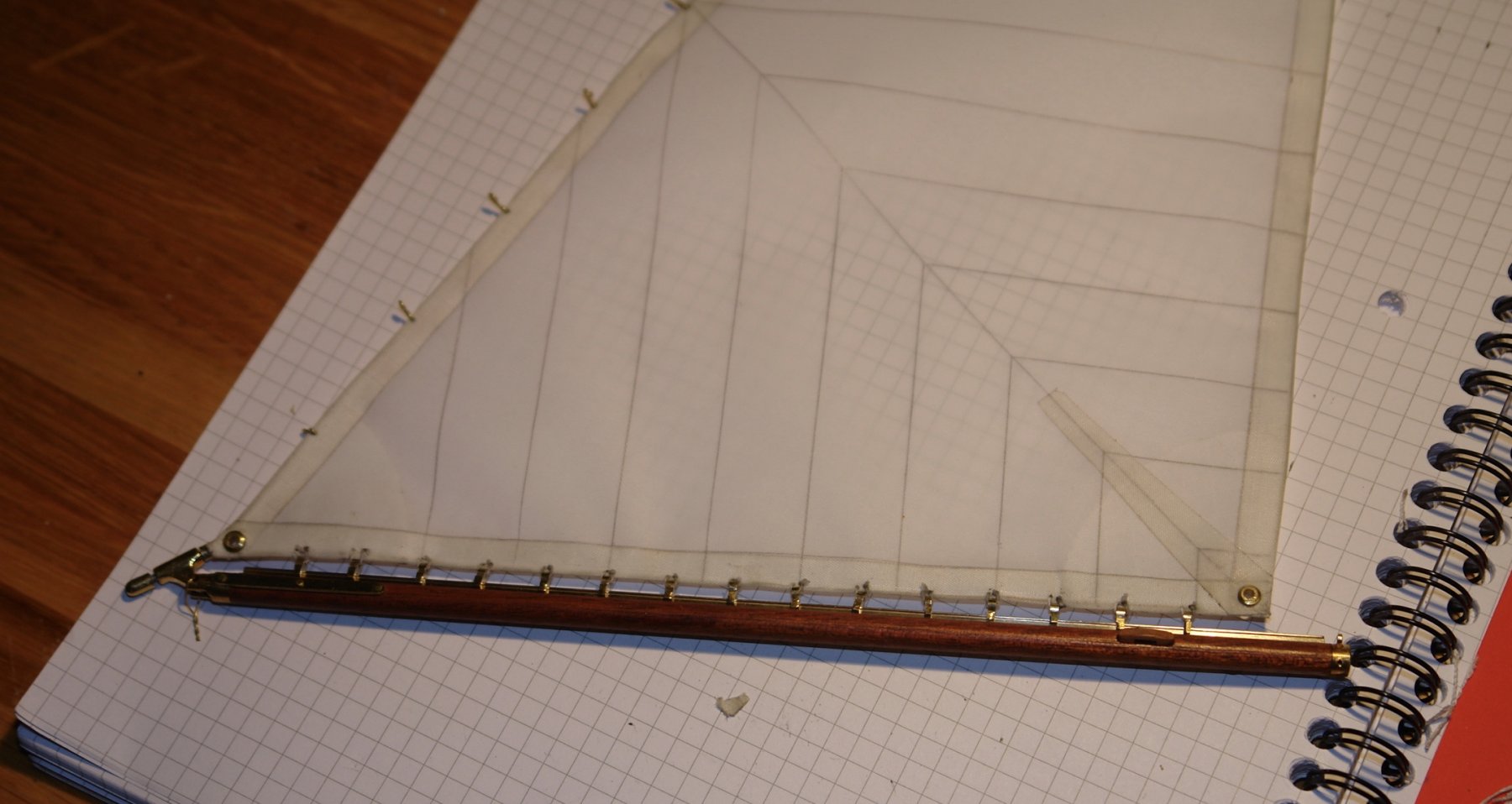
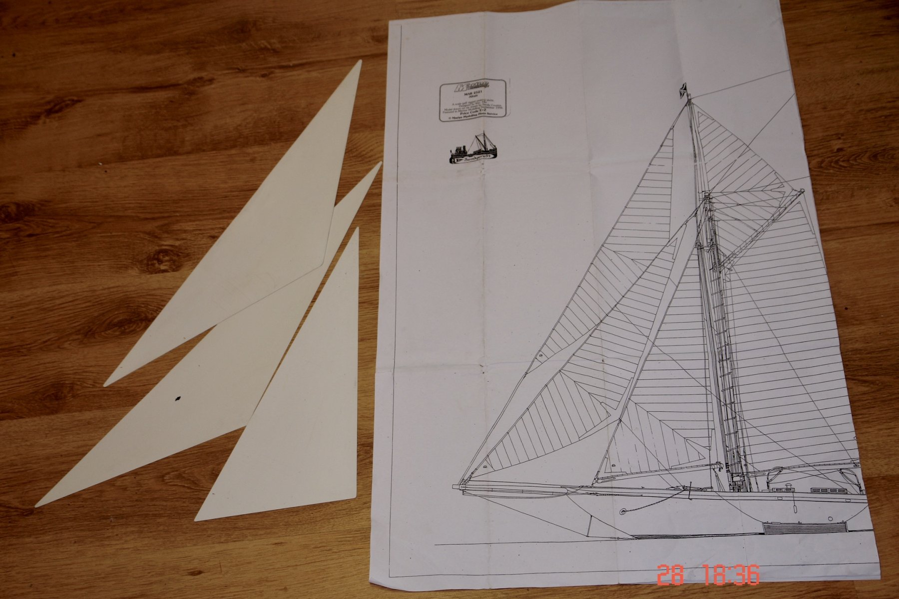
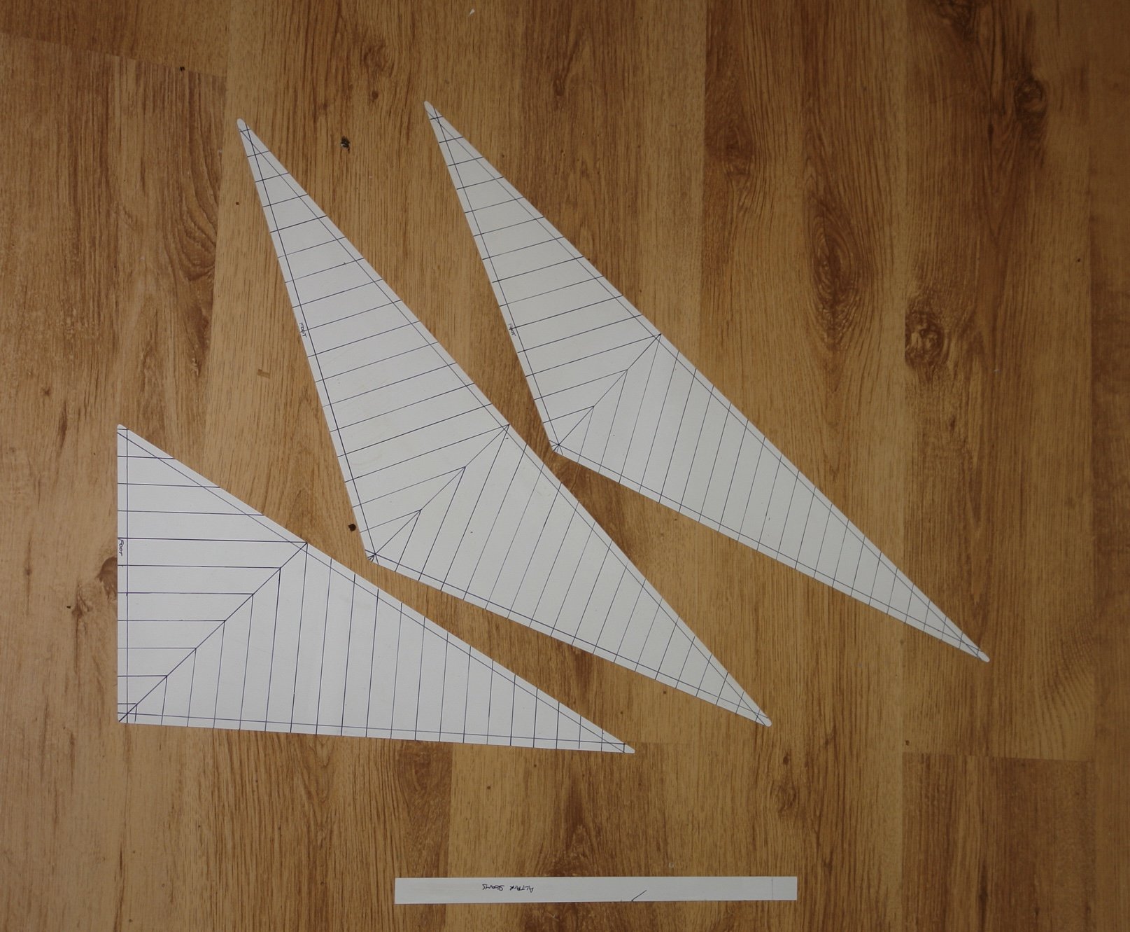
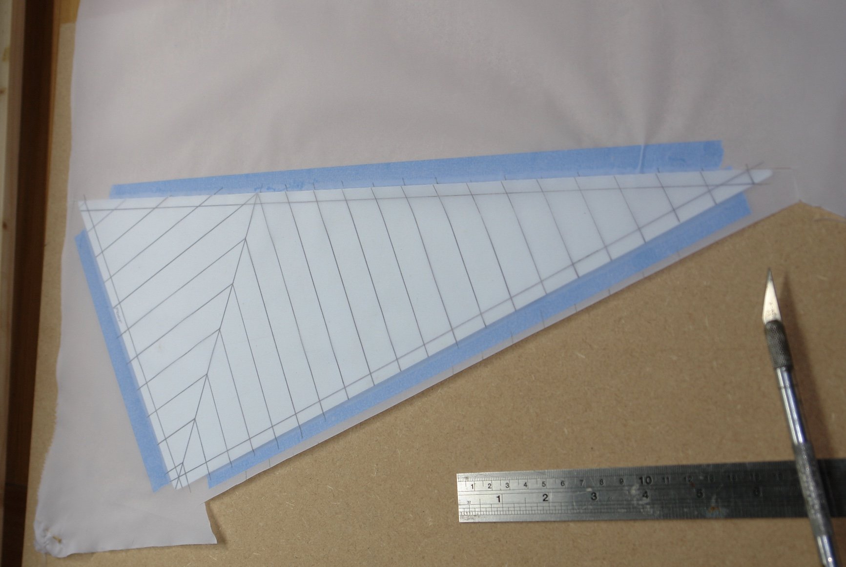
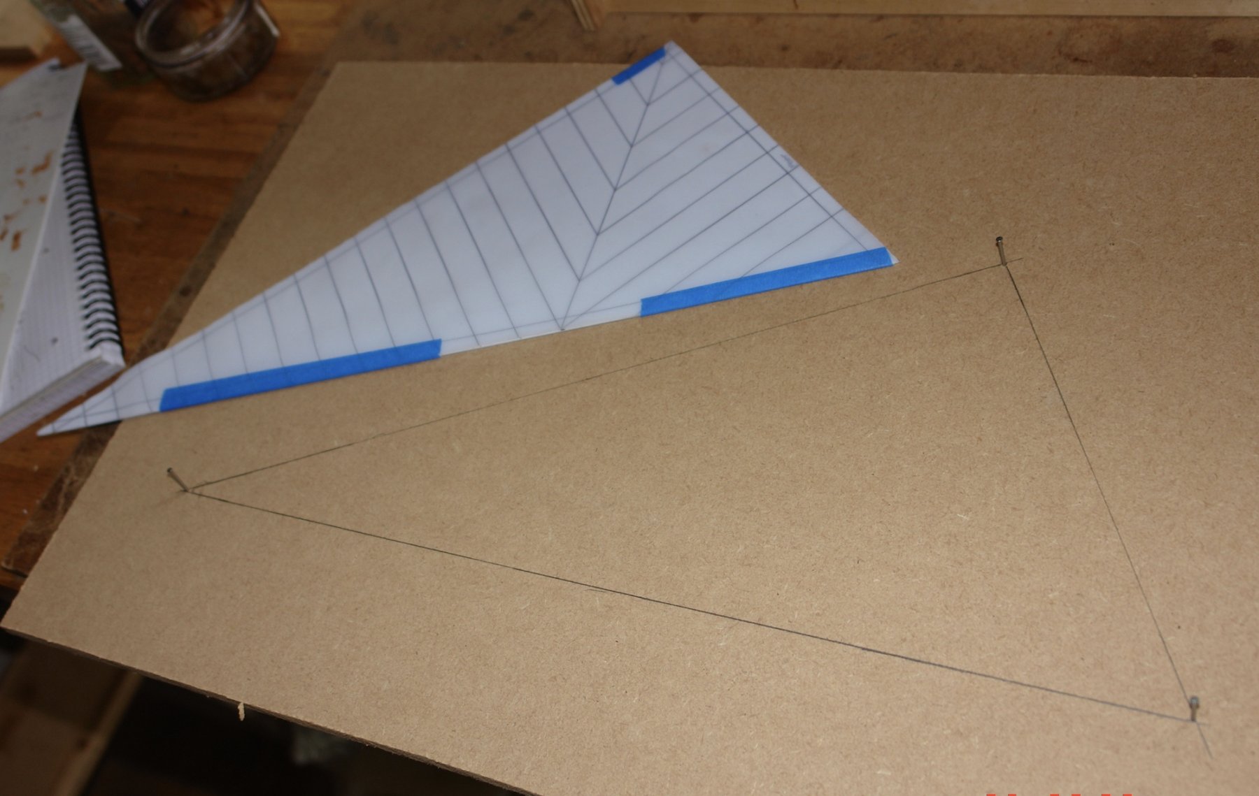
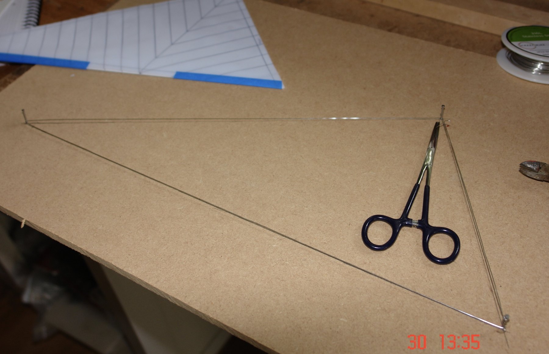
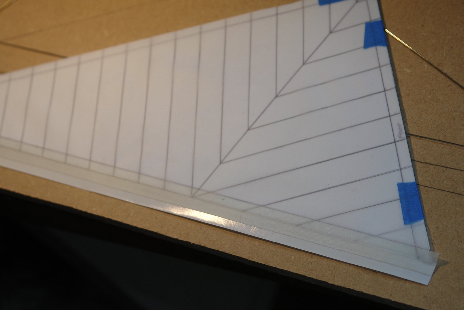
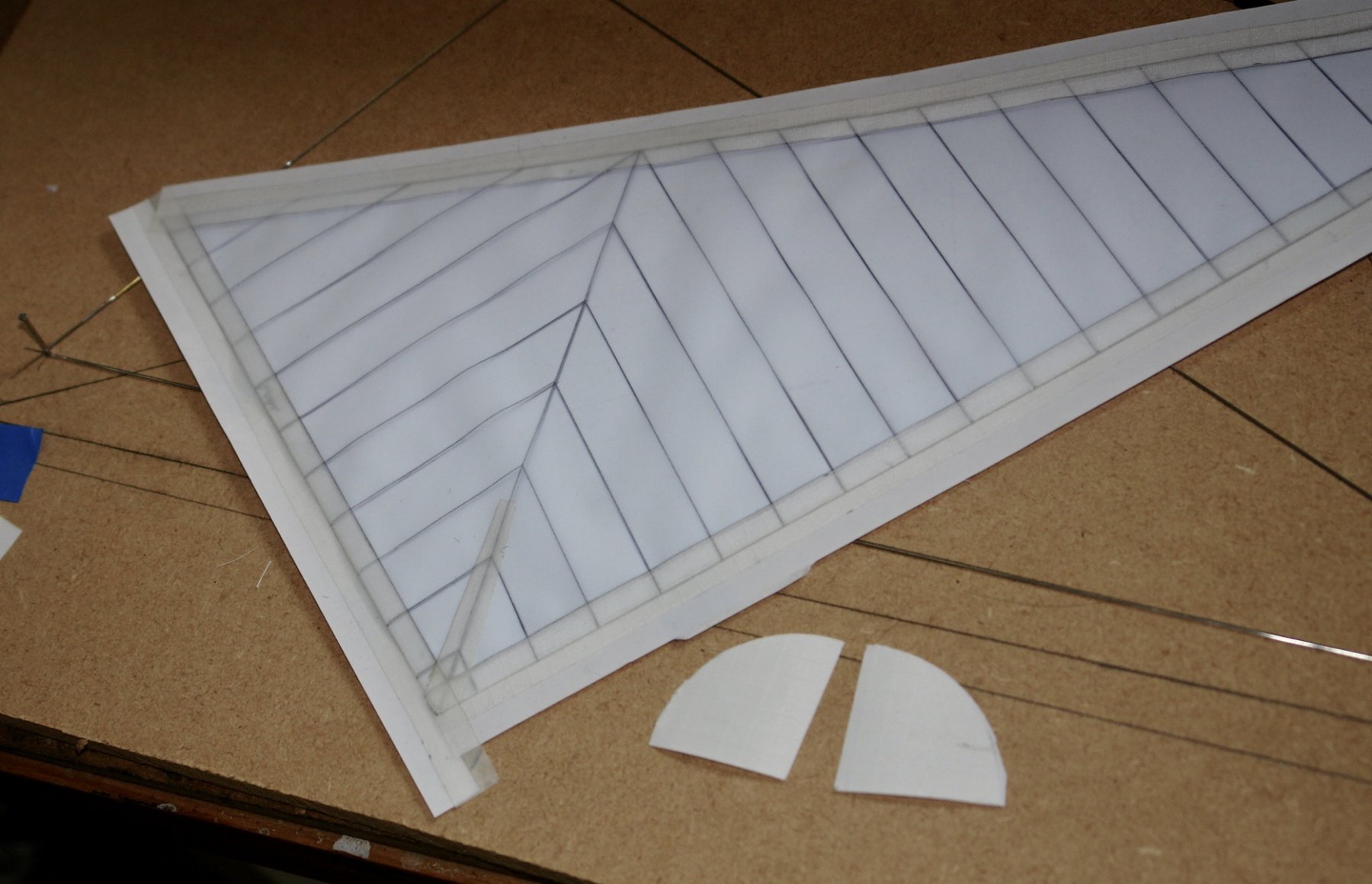
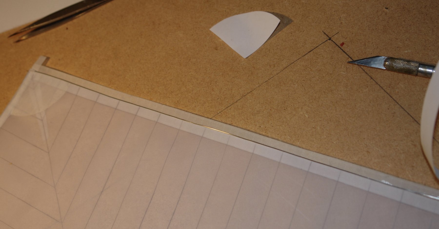
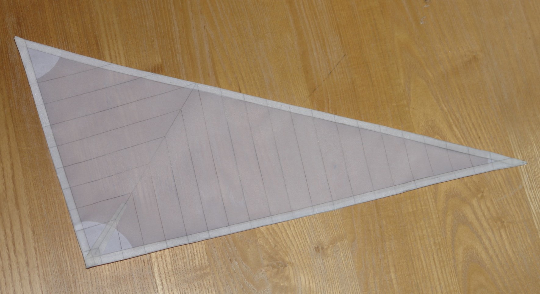
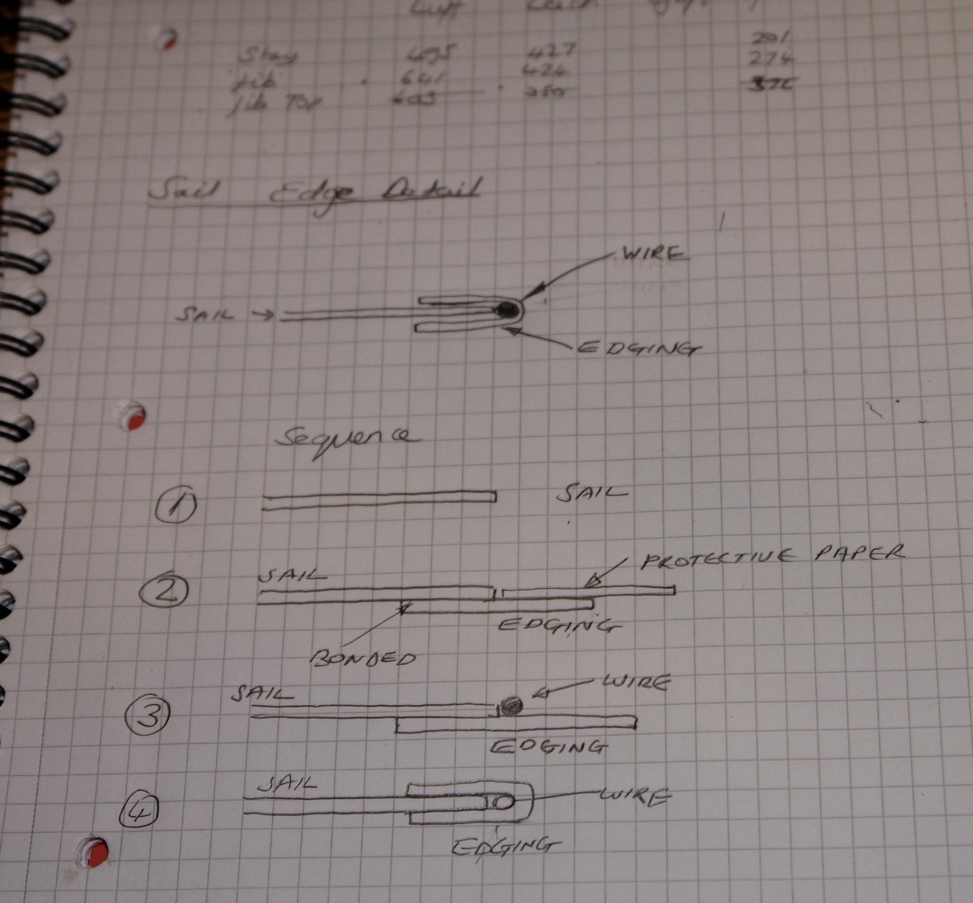
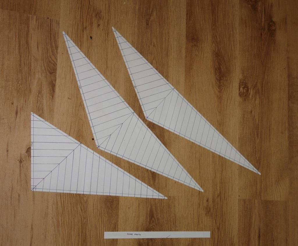
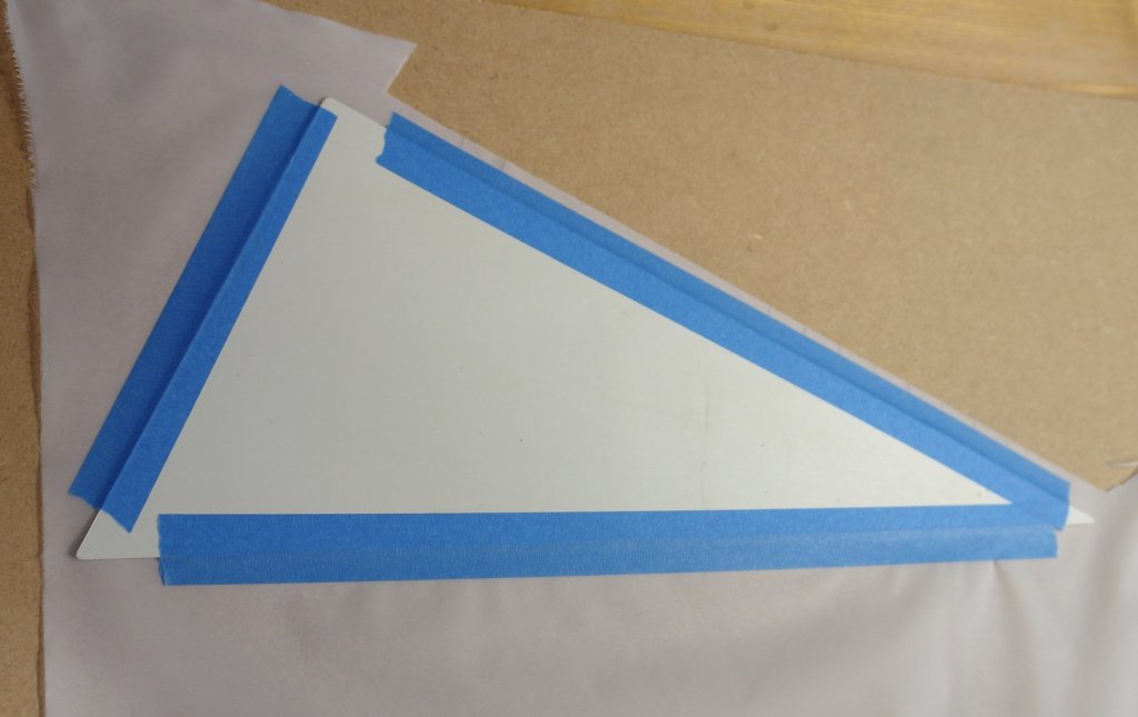
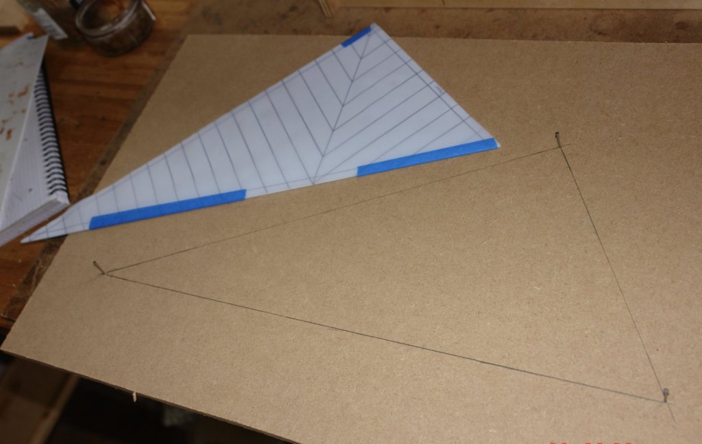
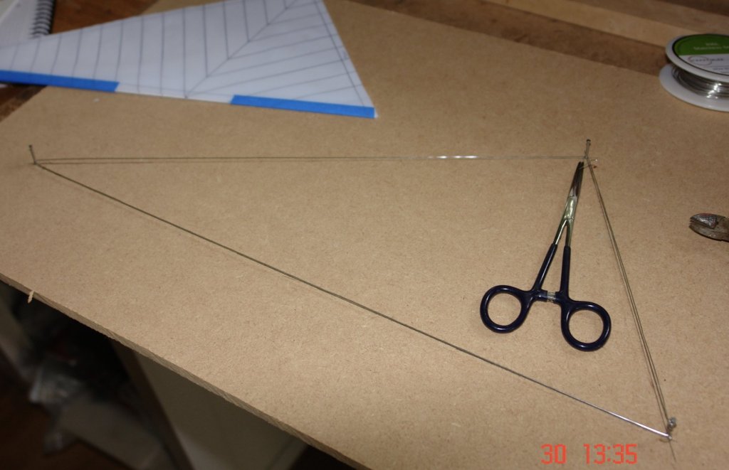
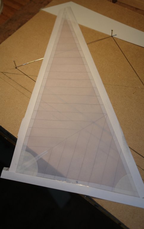
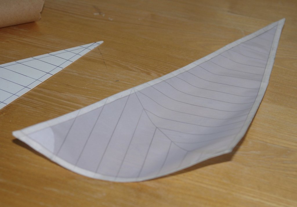
So today I made the first sail. I didn't follow convention so an apology to all you purists and perfectionists, you might want to skip this section. I wanted to make the sails in a way that would allow me to create some shape in the finished form. Flat / floppy sails in my view can spoil an otherwise excellent models. I decided I would try incorporating steel wire into the edges of the sails as a way of creating something which could be shaped. The following sketch illustrates what I decided to do. I had previously prepared the sail cloth - now with 2 coats of 50% PVA and water. It took about 24 hours to dry. I started by cutting templates for the sails. Cut from .040" plastic sheet. On to this I marked out the position of all the seams. The templates were attached to the back of the sail cloth with masking tape. The seam lines were then transferred to the cloth using pencil. No stitching for me - the scale stitch size would be much too small and my needlework skills just aren't up to it. The cloth was then cut by following the edge of the template. Additional making tape was applied to keep the cloth on the template. The template was then used to make the sail profile on a piece of MDF. Nails were place at the corners. .020" annealed stainless steel wire was then wound tightly run the nails. It was tight - pinged like a guitar string. The wire was doubled on one of the sides of the triangle. Both wires were parted by a single cut and the butt ends were joined by inserting them in a small bore tube and soldering. Half inch wide edging tape strips were cut from rip stop tape (self adhesive, very thin and very strong). These were placed 1/4 inch over the sail edge and the overhang was protected temporarily by reapplying the backing strip. The sail reinforcing detail was then added, again using the rip stop tape. At this stage the sail was offered up to the wire and the overhanging tape edges were folded over. I then tried a bit of experimental shaping. I think I might be able to simplify and possibly improve the wire insertion. I will have a go and report the results next time.


- 882 replies
-
- 11
-
-
ancre La Salamandre by tadheus - 1:24
KeithAug replied to tadheus's topic in - Build logs for subjects built 1751 - 1800
Very nice Pawel -
Byrnes table saw questions
KeithAug replied to alde's topic in Modeling tools and Workshop Equipment
Al, I don't think it your technique. I think what happens is the the pressure between the fence and the thin slitting saw blade deflects (bends) the blade away from the fence very slightly. This causes the a wedge effect which gets worse as the cut progresses. The rule relieves the sideways pressure allowing the slitting saw to run true. At least thats what I think. -
Kees - It took me a while to understand it was a plug. I should have known from your last build.
- 193 replies
-
- 5
-
-
- wilhelmina vii
- fishing
- (and 1 more)
-
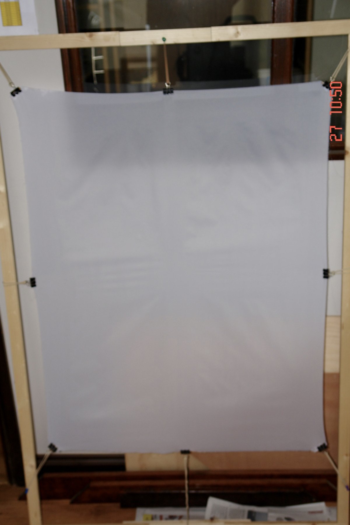
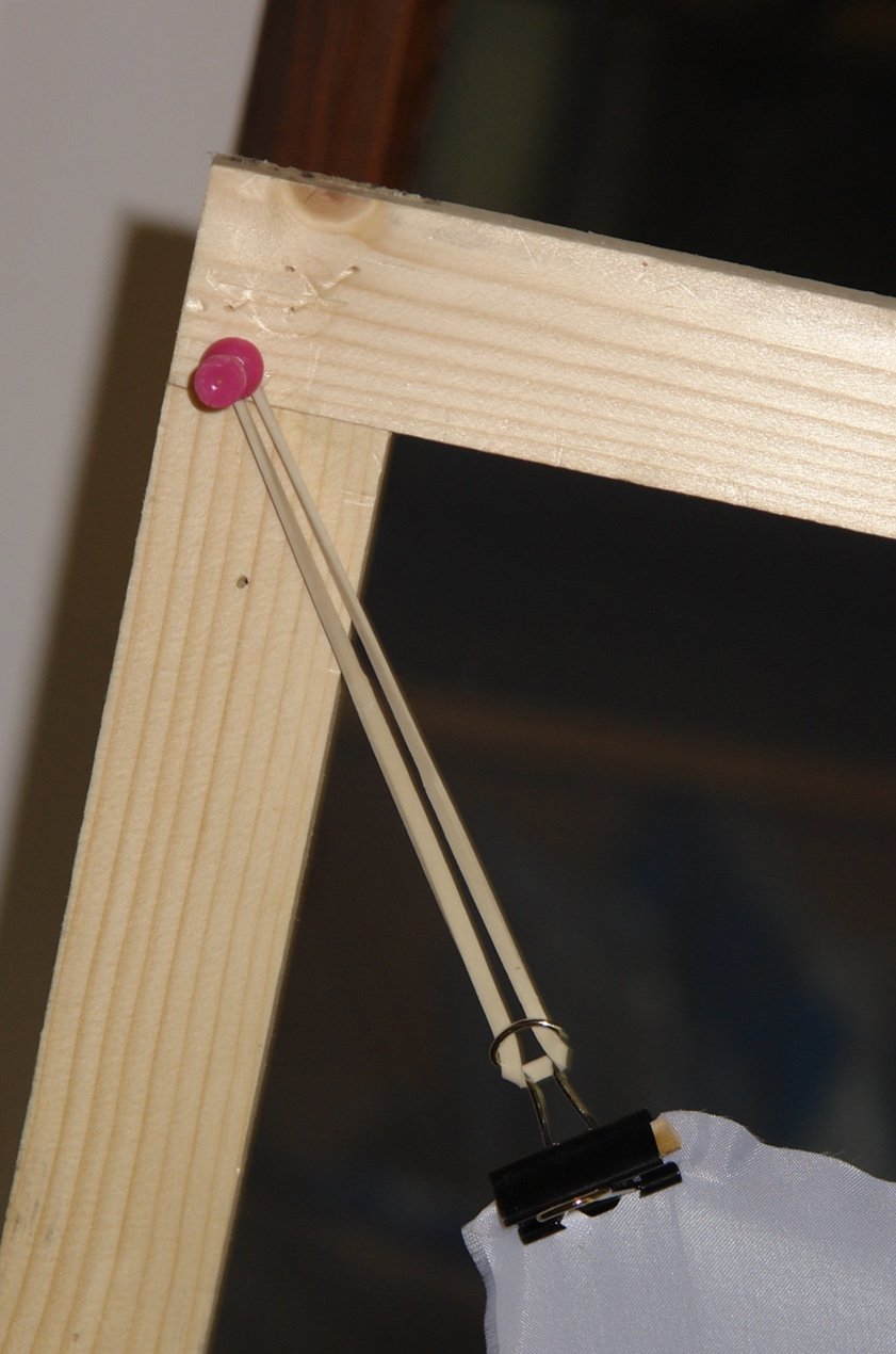
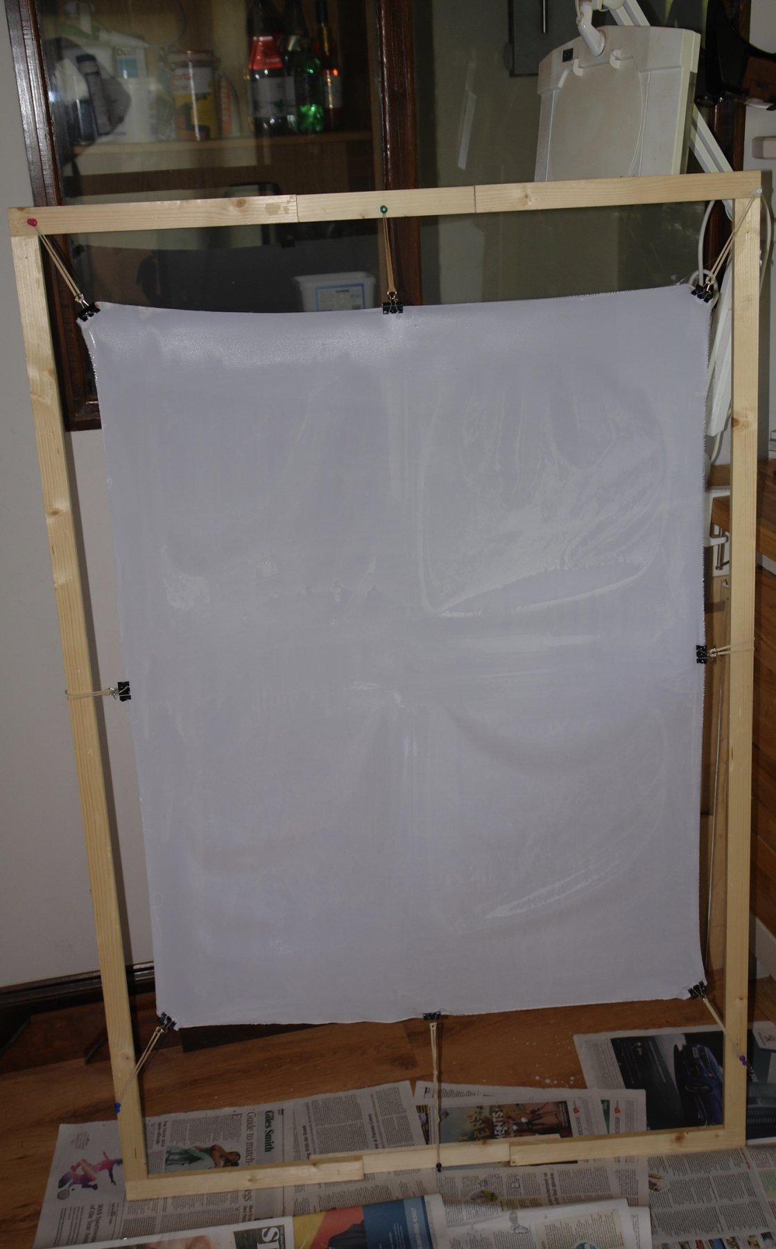
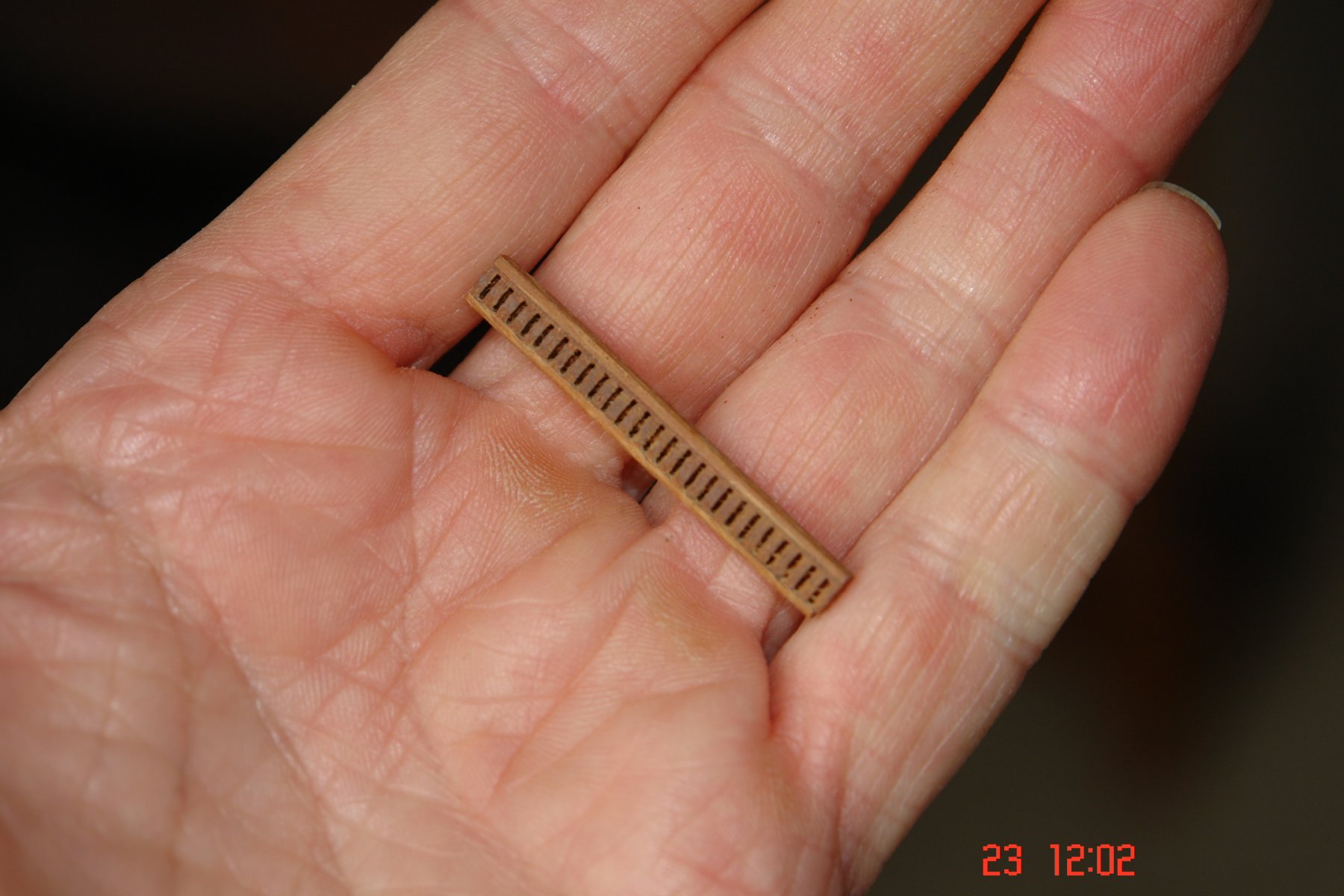
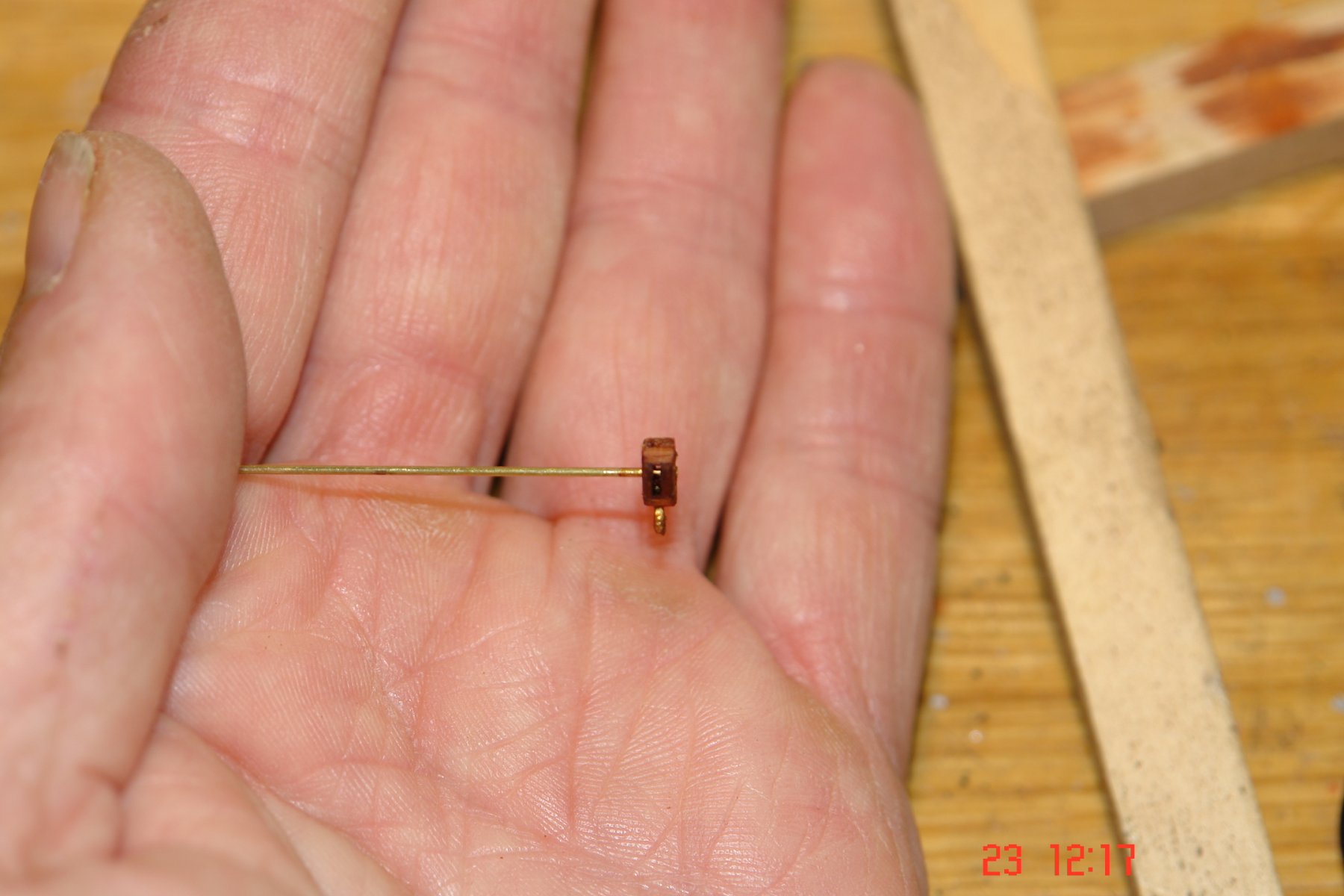
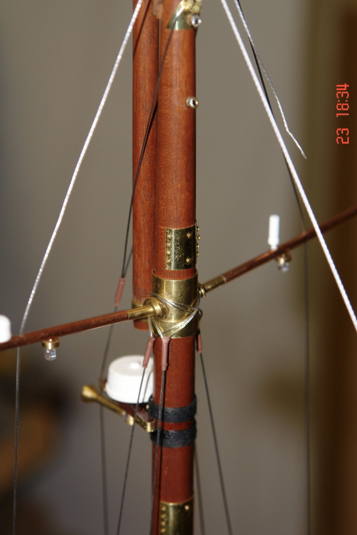
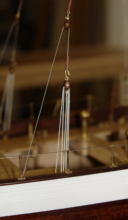
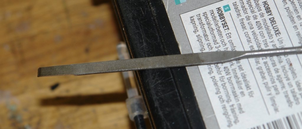
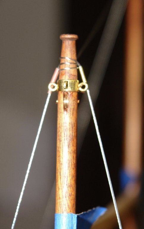
Sometimes progress feels like running up a sand dune. A couple of days ago I found a small note on the plans which required holes to be drilled horizontally through the tops of the upper masts to take the halliards for the top sails. On the face of it not a problem, that is if you ignore the fact that the holes should be slots and within the slots should be sheaves. So I spent a few days ignoring the problem of forming neat slots at the flexible and fragile ends off the masts. In the end I drilled a row of .030" holes and removed the webs with a x-acto knife. The inside of the slot was then cleaned up with a sacrificial needle file - ground thinner and narrower to get it started in the slot. I kept expecting the mast to fall apart under the cyclic load but my luck held and the job was done. The sheaves are .175" diameter by .050" wide. I rigged the lower main mast backstays - twice!! The pulleys worked - but a little too well. With a mechanical advantage of 8 (less friction) the small upper pulley was put under a load it wasn't designed for and parted with an annoying ping. I repeated the error once more before deciding the rigging didn't really need to be a taught as a guitar string. I decided I couldn't do much more rigging without mounting some of the sails so I started the process of sail making. I had a good look round at fabric options but in the end I decided to stick with the devil I know - Amati modern yacht sail cloth. I use the diluted PVA glue stiffening method and stretch the cloth on a frame to apply the liquid. I hold the tension with rubber bands. The cloth expands when wet and contracts as it dries. I find the rubber band tensioning produces a reasonably flat result. I will probably find tomorrow that this time it didn't work.


-
Byrnes table saw questions
KeithAug replied to alde's topic in Modeling tools and Workshop Equipment
Al, the carbide blade is good but because it is wider it's a little more wasteful than the .030 slitting saw blade that I typically use to rip planks. The slitting saw blade also produces a superior finish. You might want to try the slitting saw blade with the attached rule trick some time. But for now I'm pleased you are ripping good planks. -
Kees - I do find you construction approach very interesting. I looks good.
- 193 replies
-
- 6
-
-
- wilhelmina vii
- fishing
- (and 1 more)
-
Any model steam engine builders here?
KeithAug replied to Moxis's topic in Metal Work, Soldering and Metal Fittings
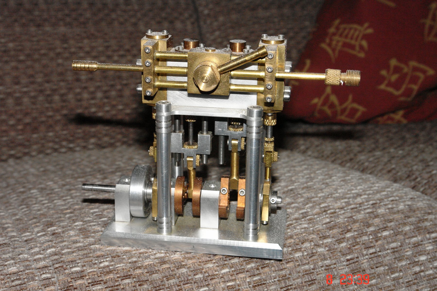
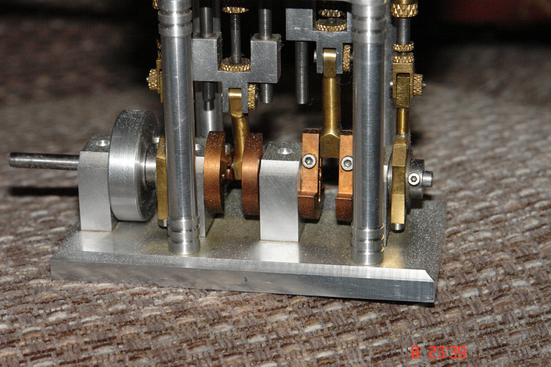
Moxis It makes up into quite a nice and interesting model. The pistons are double acting which mean it self starts. The valve allows the steam and exhaust ports to be reversed which means the engine can be reversed. The valve also allows the engine speed to be adjusted between dead slow and very fast. Have fun - a build log would be good as I am sure you will get a lot of interest. -
Any model steam engine builders here?
KeithAug replied to Moxis's topic in Metal Work, Soldering and Metal Fittings
Moxis You can find all the instructions here:- http://www.machinistblog.com/bogstandards-paddleduck-engine-plans/ -
Any model steam engine builders here?
KeithAug replied to Moxis's topic in Metal Work, Soldering and Metal Fittings
Moxis - I dont think you need to be as good as 1/100 mm. Half that is fine 1/1000 inch in my way of working. Bores can be finished with a reamer which easily gives this accuracy. Here is one I did earlier:-

-
Byrnes table saw questions
KeithAug replied to alde's topic in Modeling tools and Workshop Equipment
The table has an accurately aligned table and fence but the front fence locking thumb wheel must always be tightened first and without any side pressure on the fence -
Any model steam engine builders here?
KeithAug replied to Moxis's topic in Metal Work, Soldering and Metal Fittings
Moxis. The difficulty really depends on the type of machinery you have available and what experience you have of using it. Do you have access to a metal working lathe and milling machine and the tooling that goes with them? Rather than go straight to the expense and complexity of a kit compound engine I would suggest you try something simpler like a wobbler first to build up your skills. You can find designs on the web. Alternatively you can try something a bit more complex like a "paddle duck". Good designs and build instructions are also available on the internet. -
Thanks Grant, your improvements make a lot of sense. I find I get a lot of use out of mine, I even used it for machining out the tennons on some table legs a couple of weeks ago.
-
Thank you, I'll try it some time.
-
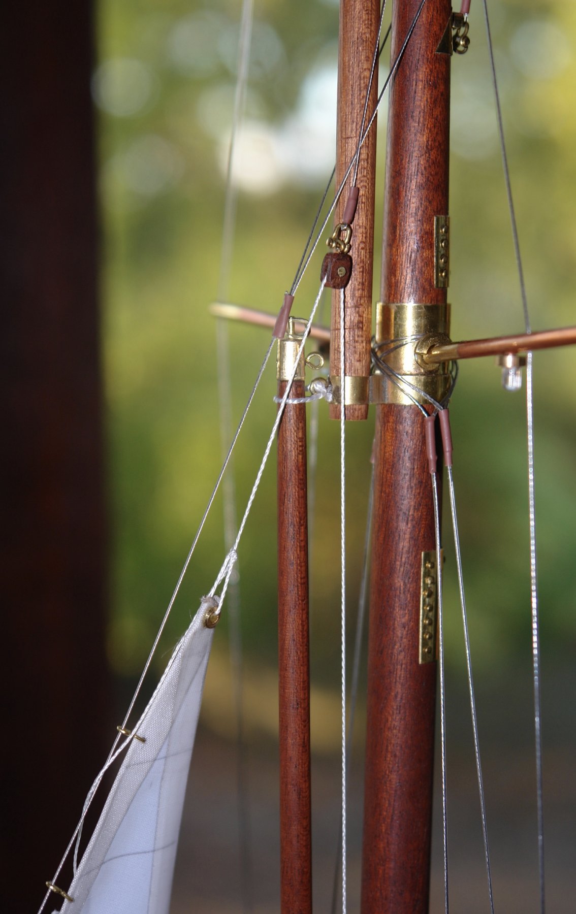
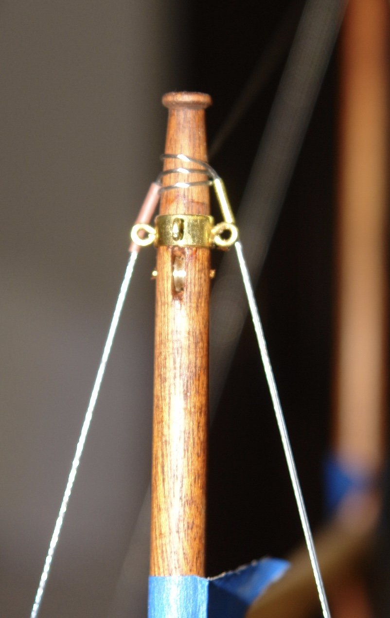
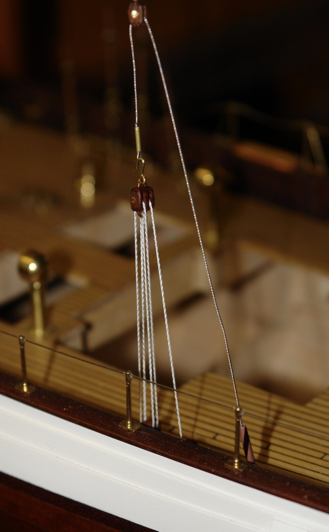
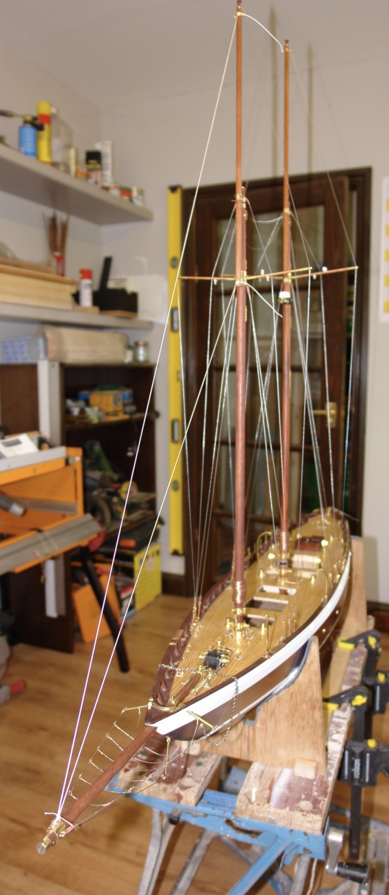
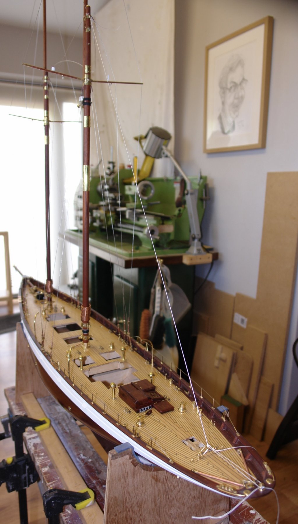
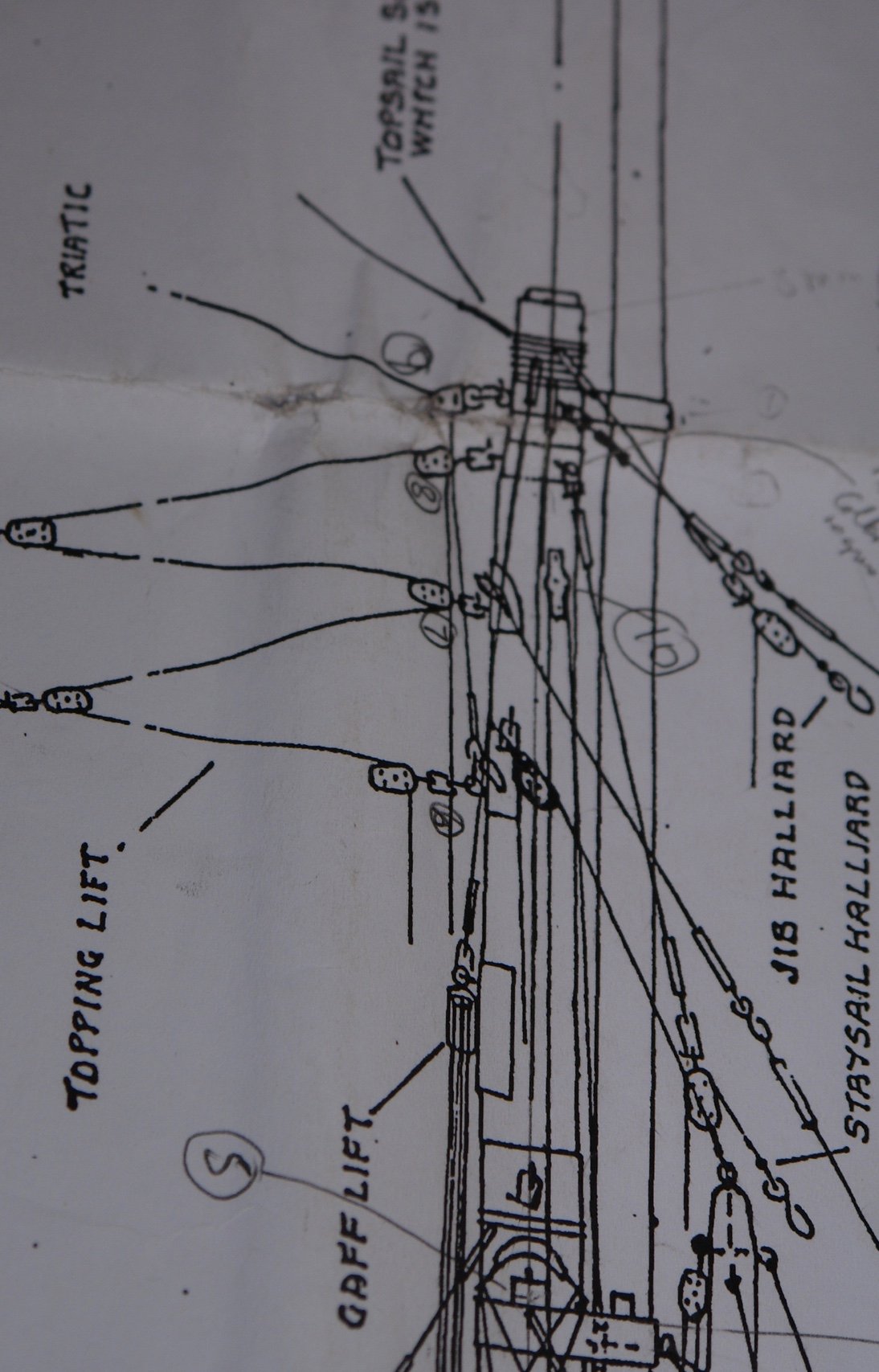
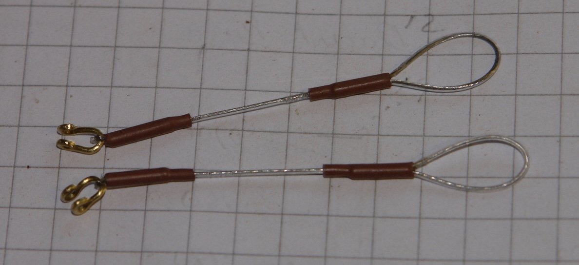
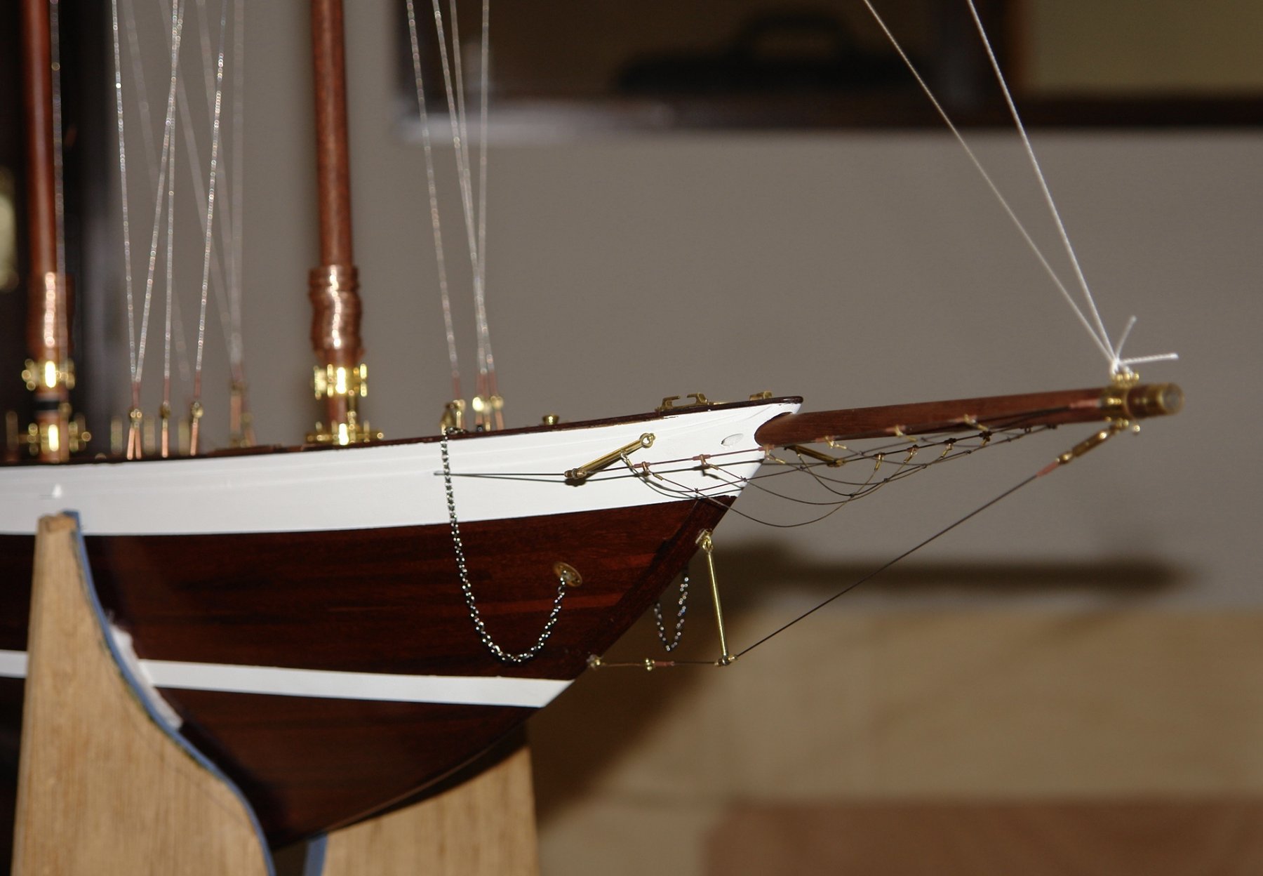
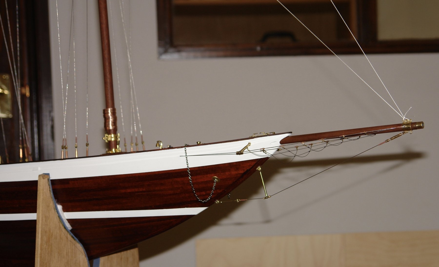
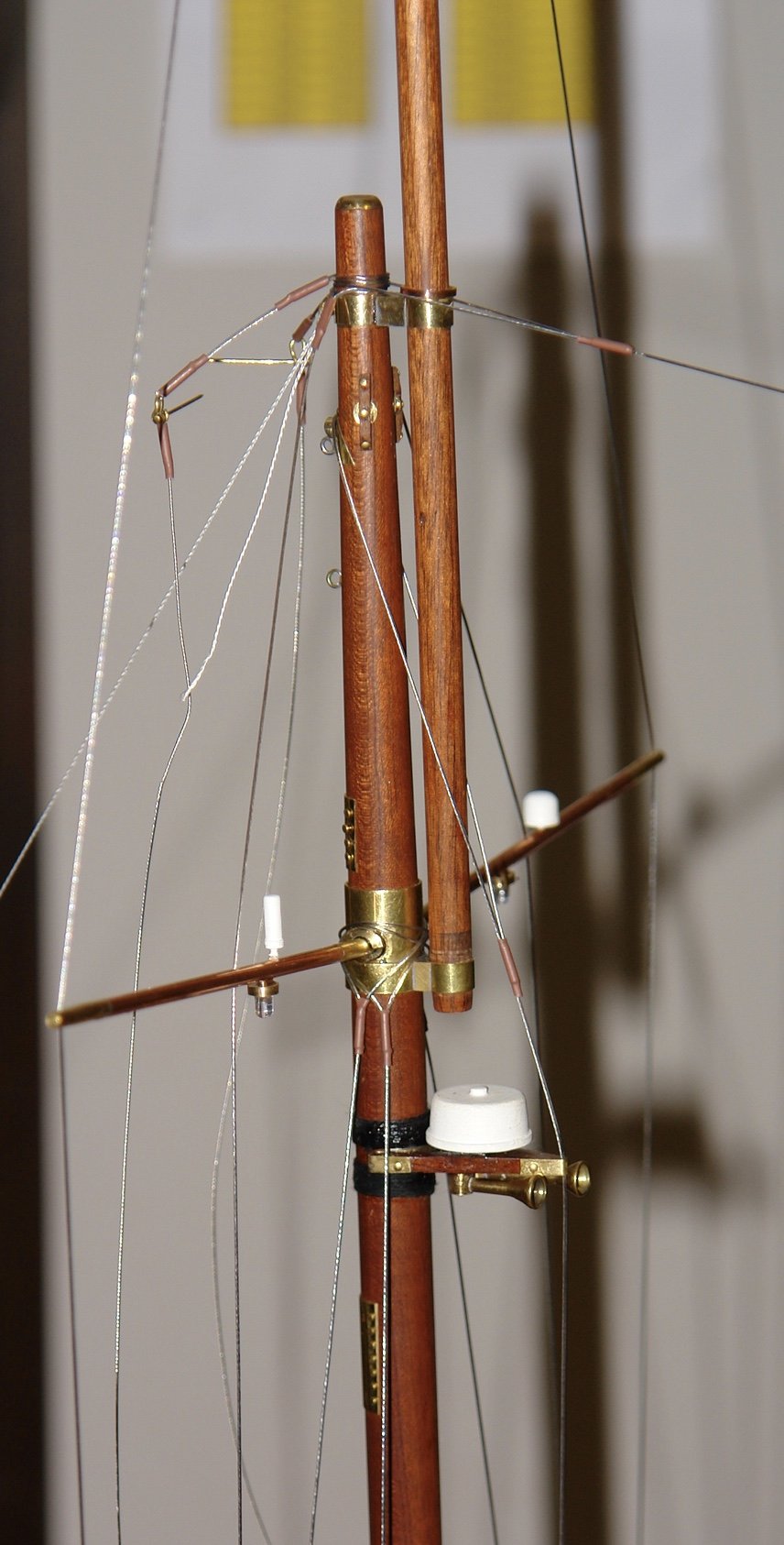
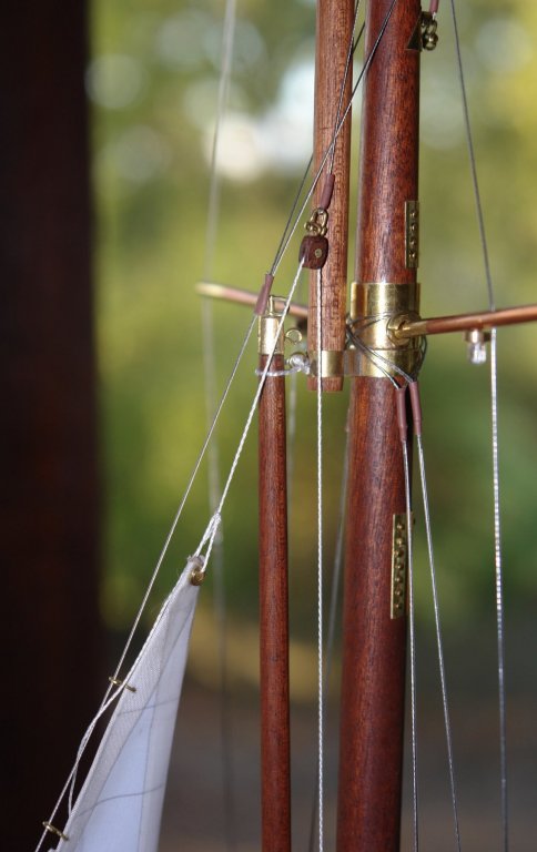
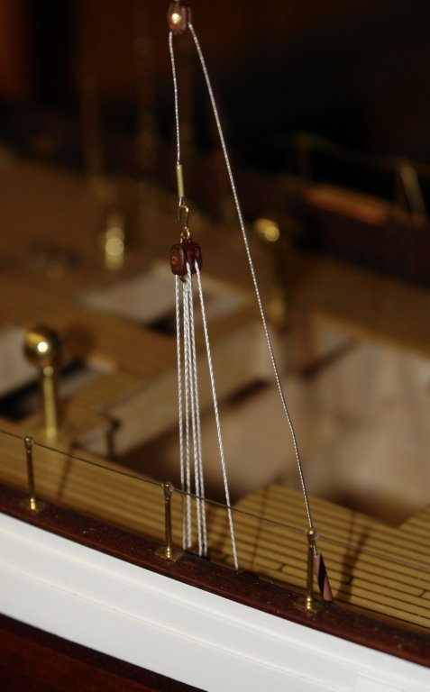
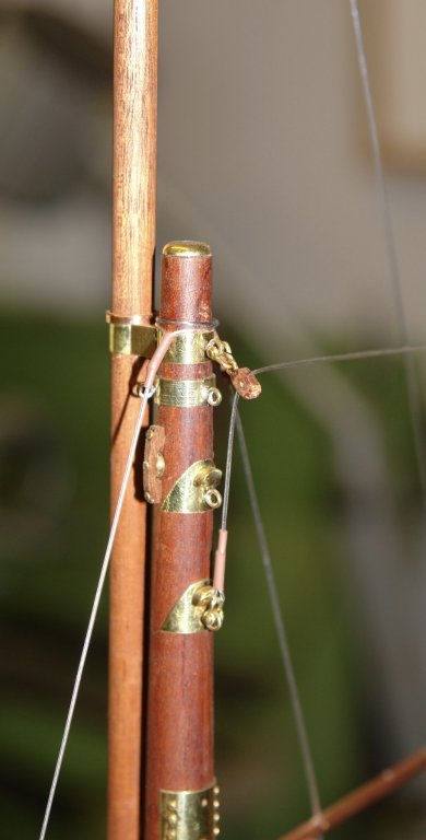
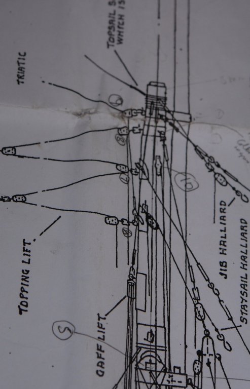
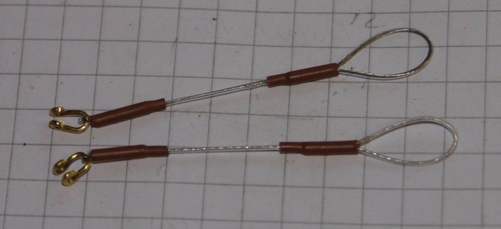
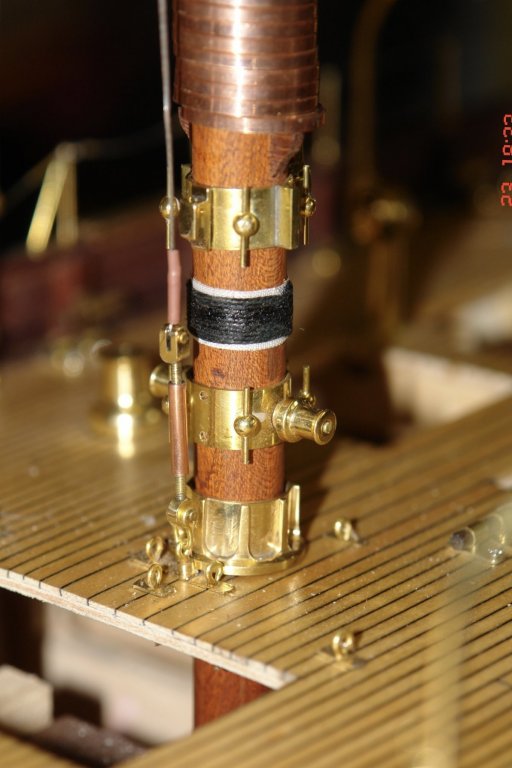
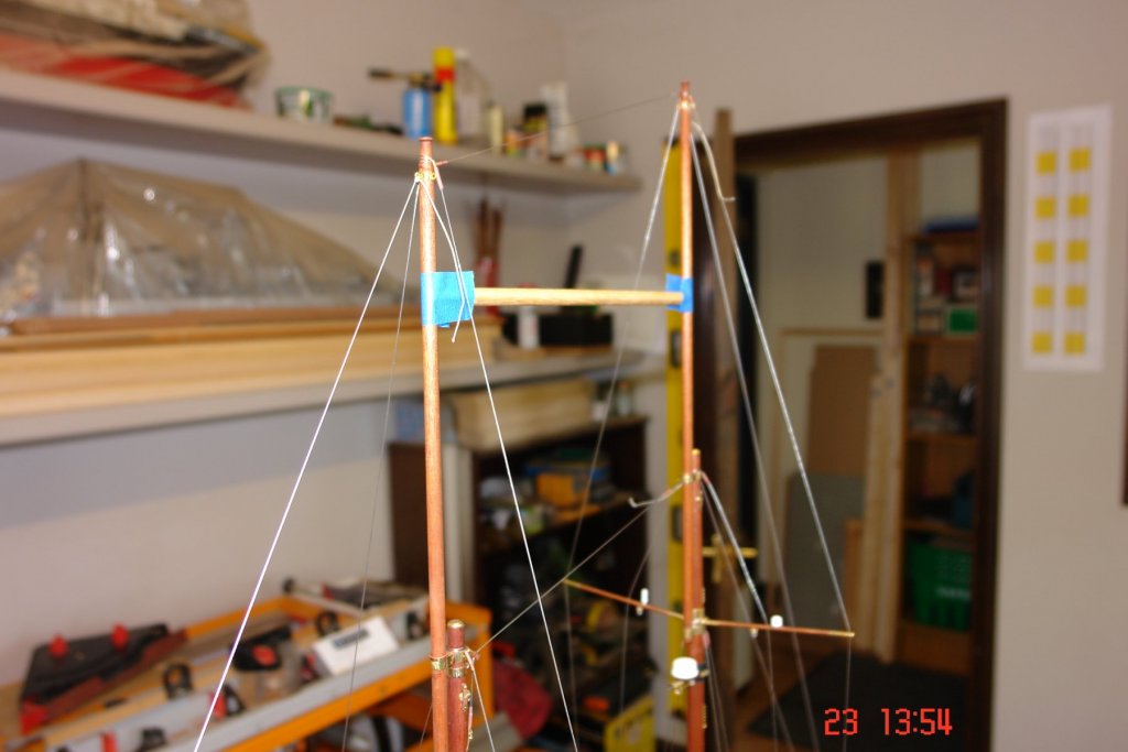
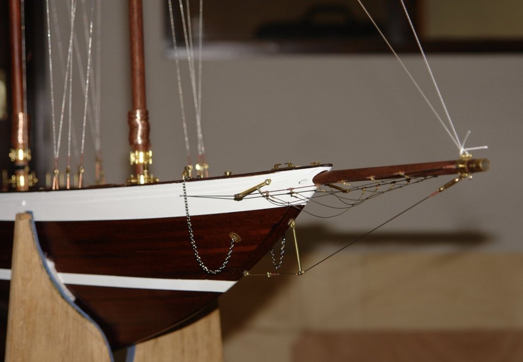
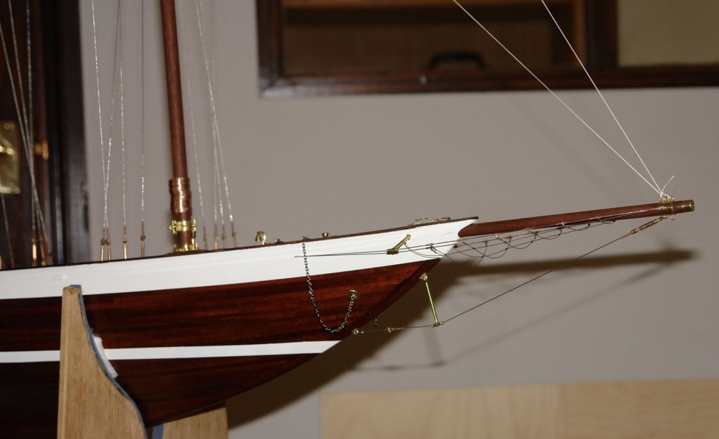
And so back to rigging. I had to give a bit of thought to the sequence of rigging the stays. I wanted to make sure that I didn't lock in any unwanted distortions due to rigging tension before all stays were in place. I started by rigging the boom stay. This had a few elements to it which gave interest. Having braced the boom I then used fishing line thread to put temporary stays in place to brace the fore and main masts. I then checked the that the masts were parallel using the previously made gauge stick. I taped this in place while I rigged the triatic and spring stay. The triatic fixing to the fore mast is to my mind a bit odd as it passes through a block before attaching a few inches lower. I don't really see what this achieves other than to obstruct the lower attachment points. I suspect someone will know why its designed like this???? The bracing shroud in front of the main mast was installed next. This passes through the front of the "A" frame which supports the radar and terminates at a turnbuckle at the base of the mast. Finally a close of the strops for the lower main mast back stays. About 1.250 inches long. The shackles are about 1/8" high Despite my block production of the previous day I hadn't made up the smallest blocks, and of course today this was the only size I needed - for the triatic block.


-
Seren, It looks like an interesting and challenging model. Welcome aboard and good luck with the build.