KeithAug
-
Posts
3,986 -
Joined
-
Last visited
Content Type
Profiles
Forums
Gallery
Events
Everything posted by KeithAug
-
 Fascinating build John. love the strakes and feathers. Very interesting plank bender, I think I will copy that when I am next fed baked beans for dinner.
 -
Thank you Michael. Im saving rope making for my next build, once I have made a rope walk, and a rear tool post, and a table for the scroll saw, and decorated the games room, and, and, and - life is just too short.
-
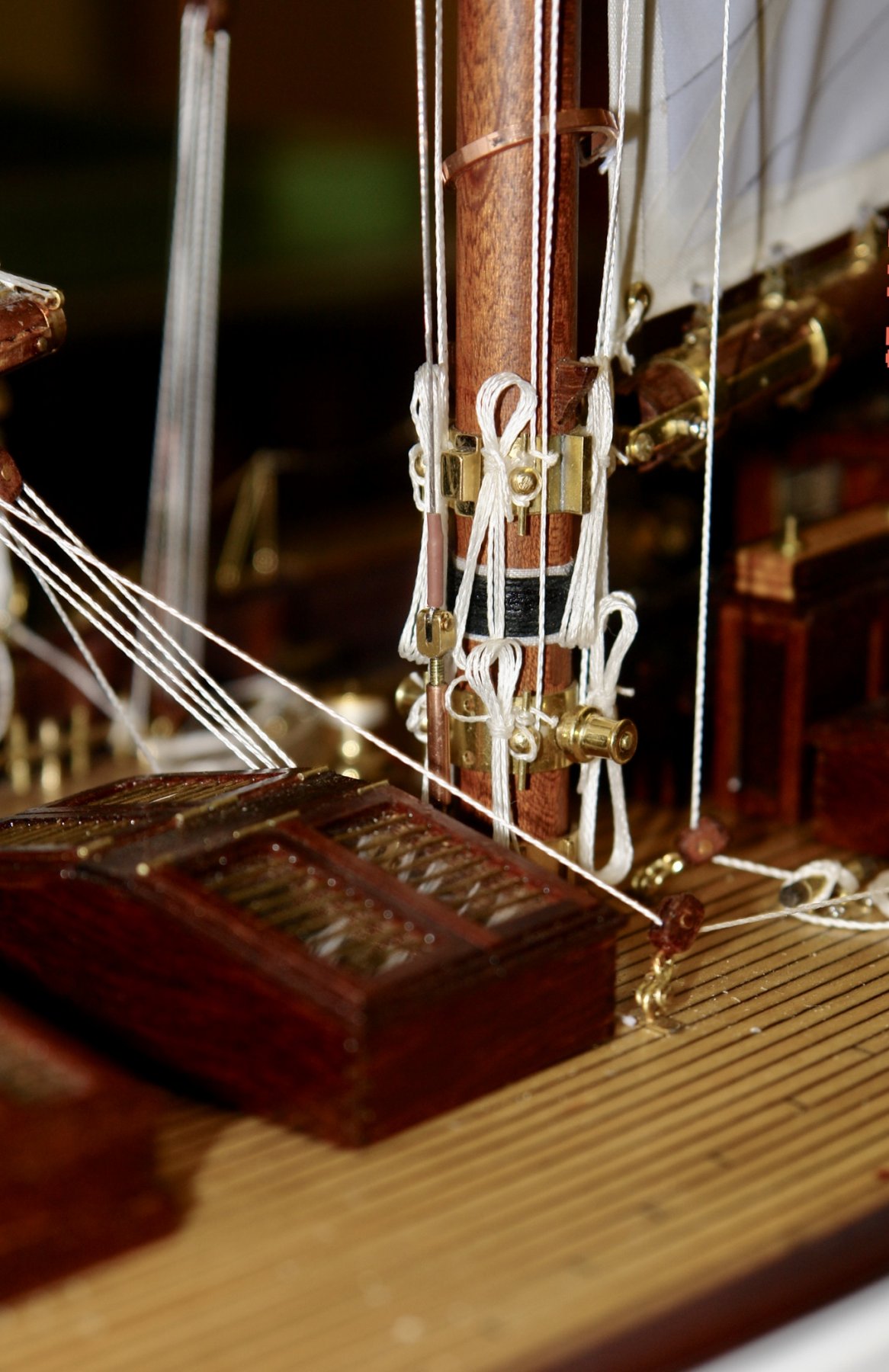
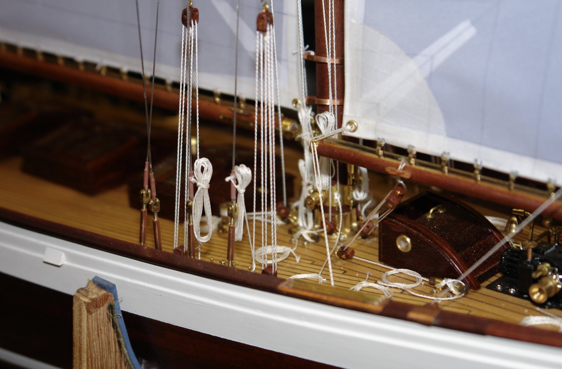
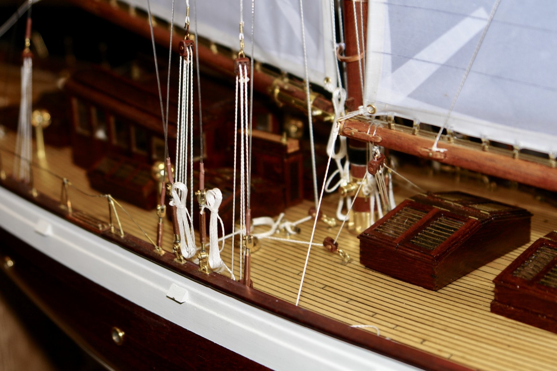
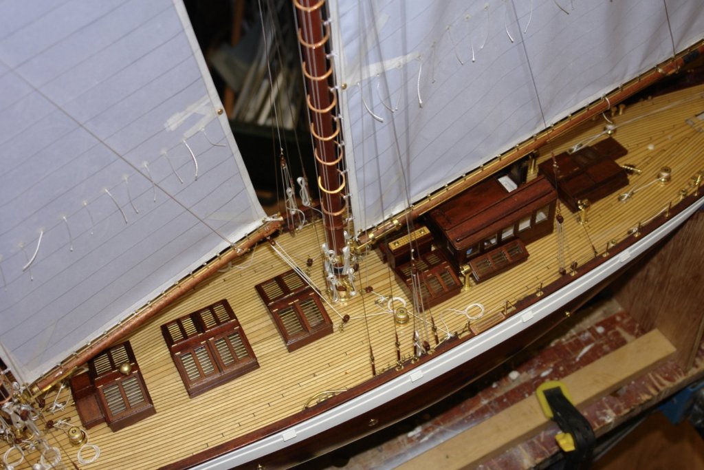
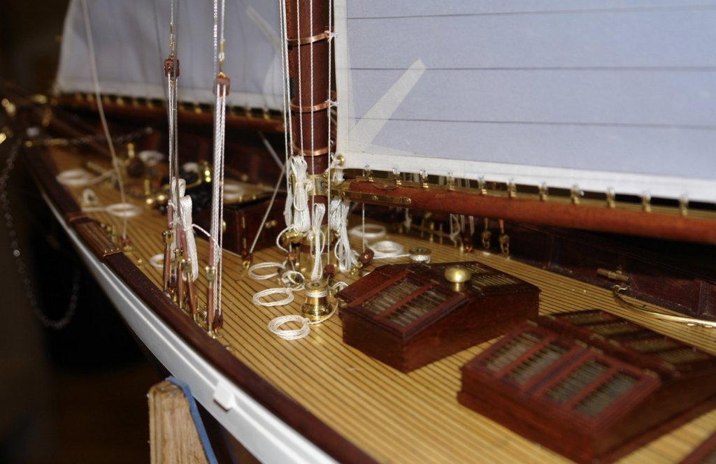
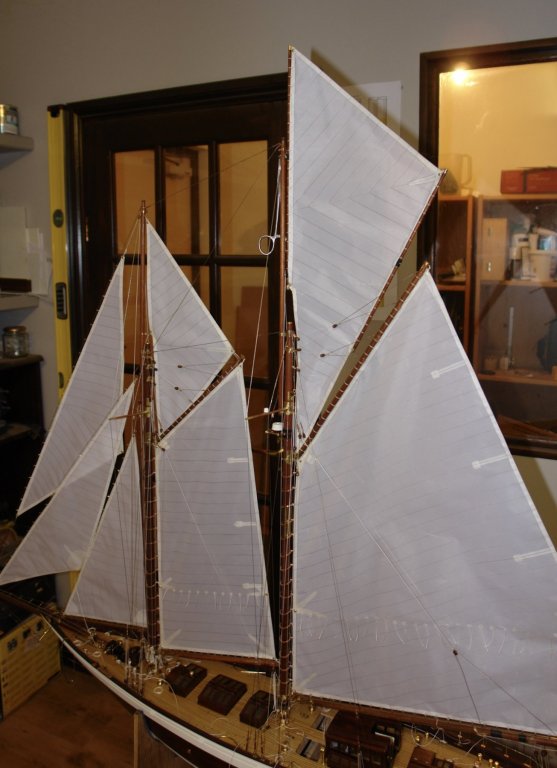
I have been continuing with the rigging - still a bit to do though. It does not seem as though I have made much progress over the last week despite having been in the workshop for quite a few hours. Perhaps its just a slow part of the build. I completed the sheets on the main top sail. The topmast lift and numerous other lines. Once more I ended up with a rats nest of lines on the deck. The piece of wood with metal pegs is my rope coiling tool. Some time later all was tidy.


-
Jet or Dewalt scroll saw
KeithAug replied to Anguirel's topic in Modeling tools and Workshop Equipment
I seem to recall flowers for the wife was a suggestion!!!!!!!!! -
Coming along very well. Nice hoops - how were they made?
-
Hi Nils He looks like he ate too many pies, or is it a beer belly?
- 692 replies
-
- 6
-

-
- eagle of algier
- chebec
- (and 2 more)
-
Deck is looking really nice Per. Re your comment:- Have you tried mixing a little deck sanding dust with PVA and filling the areas you are concerned about with the mixture?
-
Congratulations Adrian on completing a lovely build. Maybe now is the time to start thinking about building the new Cromer Liifeboat.
- 184 replies
-
- 3
-
-
- ruby & arthur reed
- lifeboat
- (and 1 more)
-
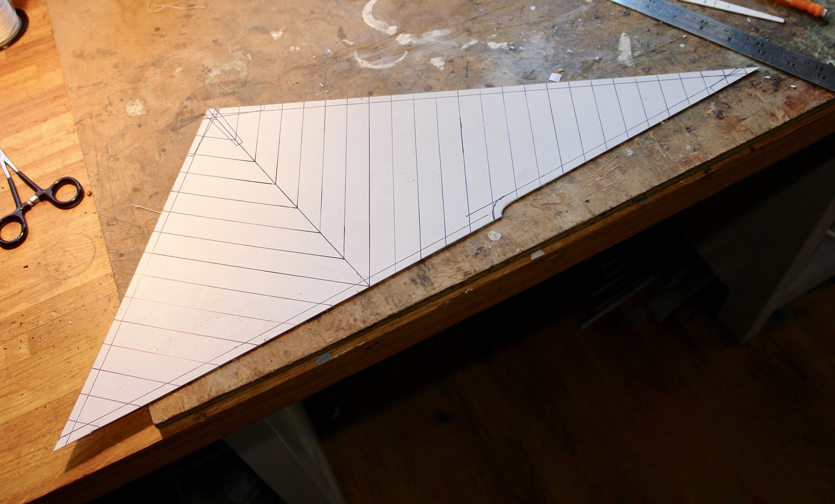
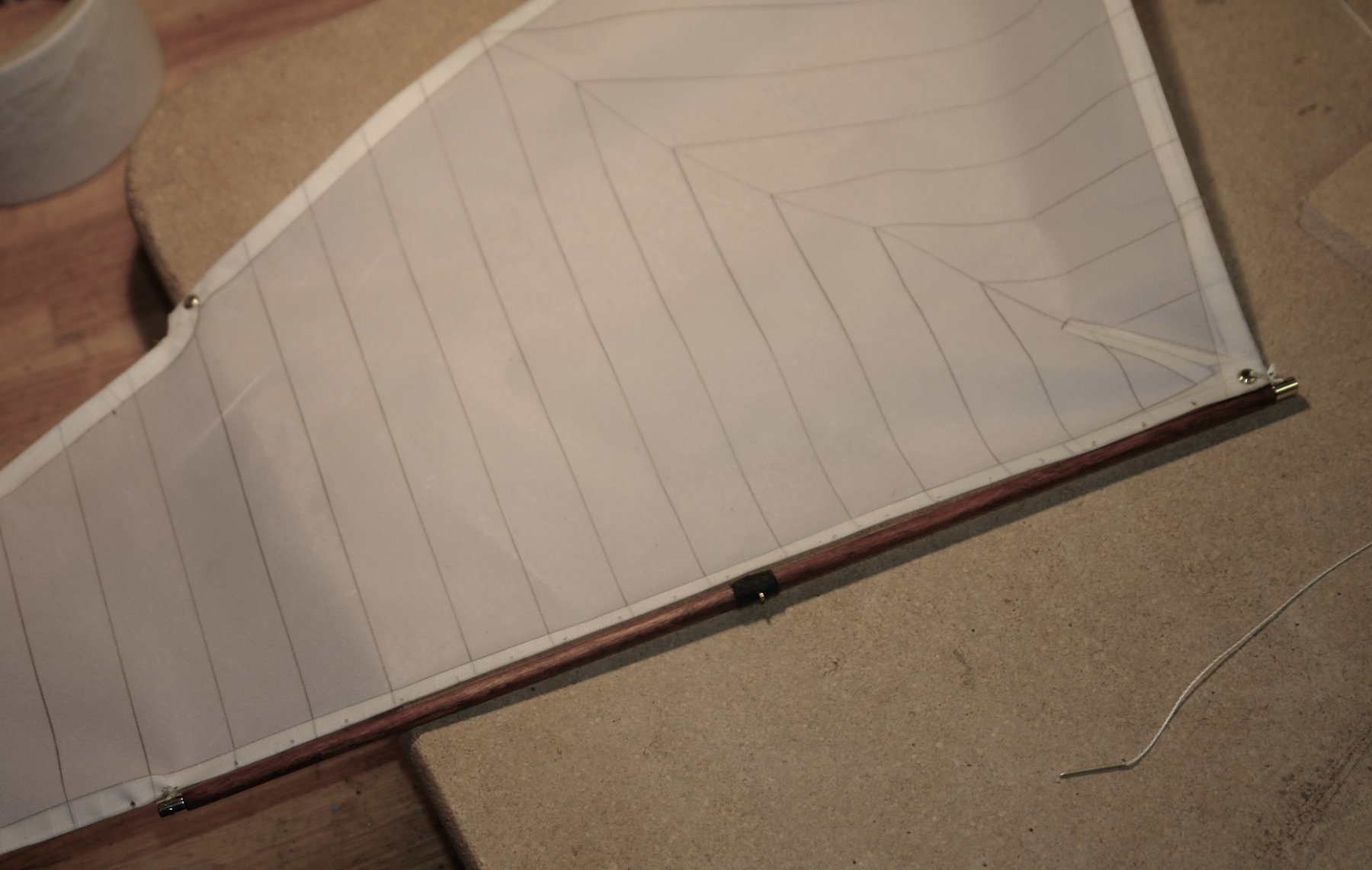
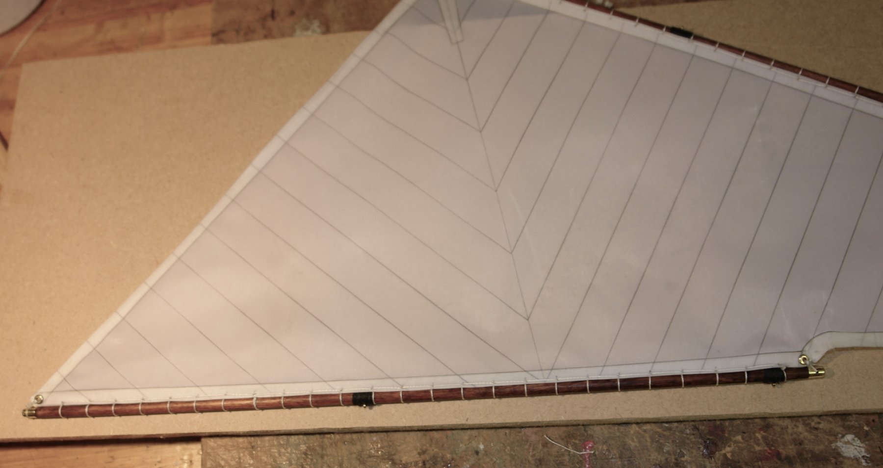
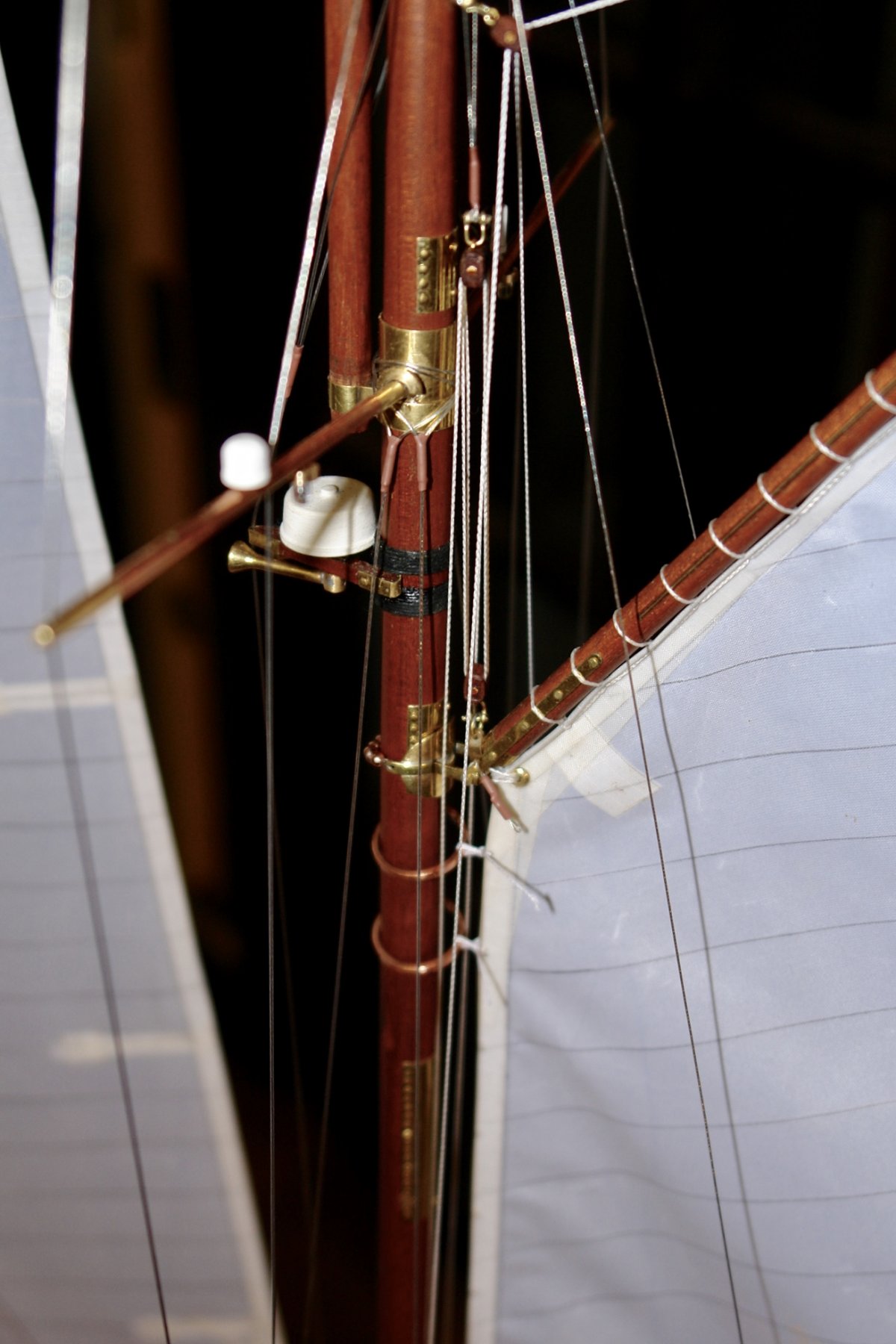
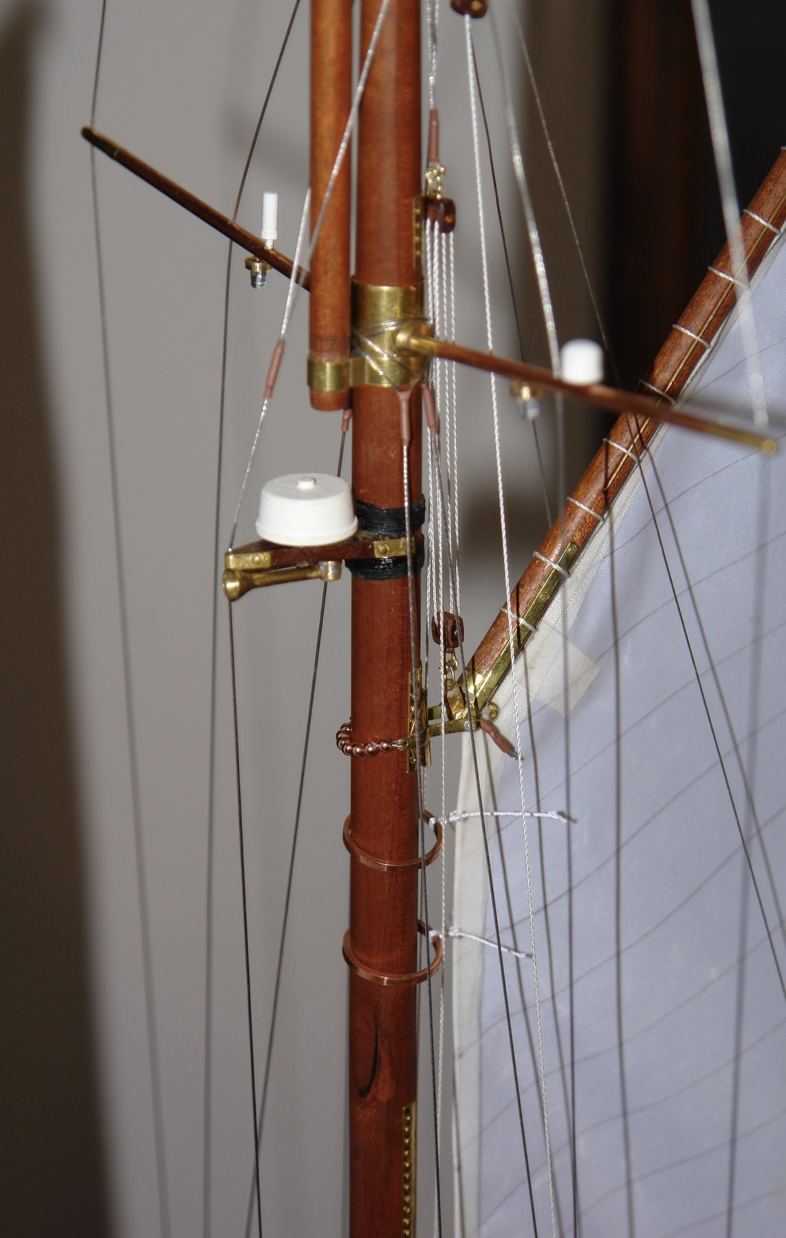
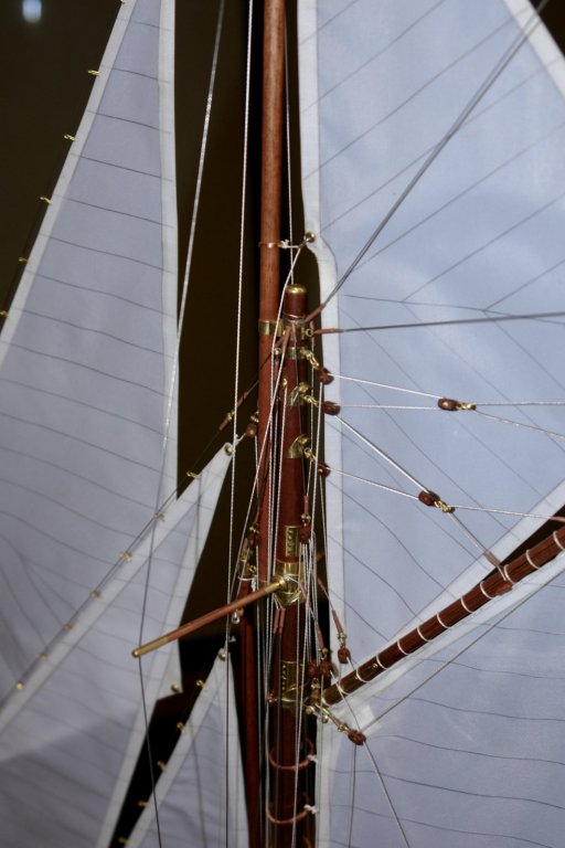
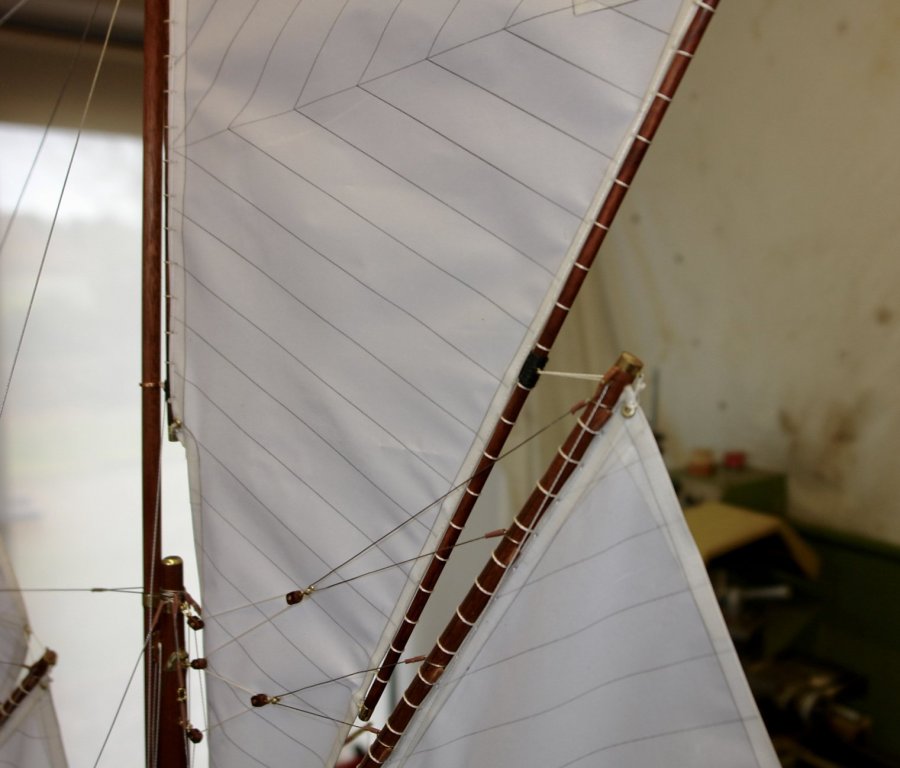
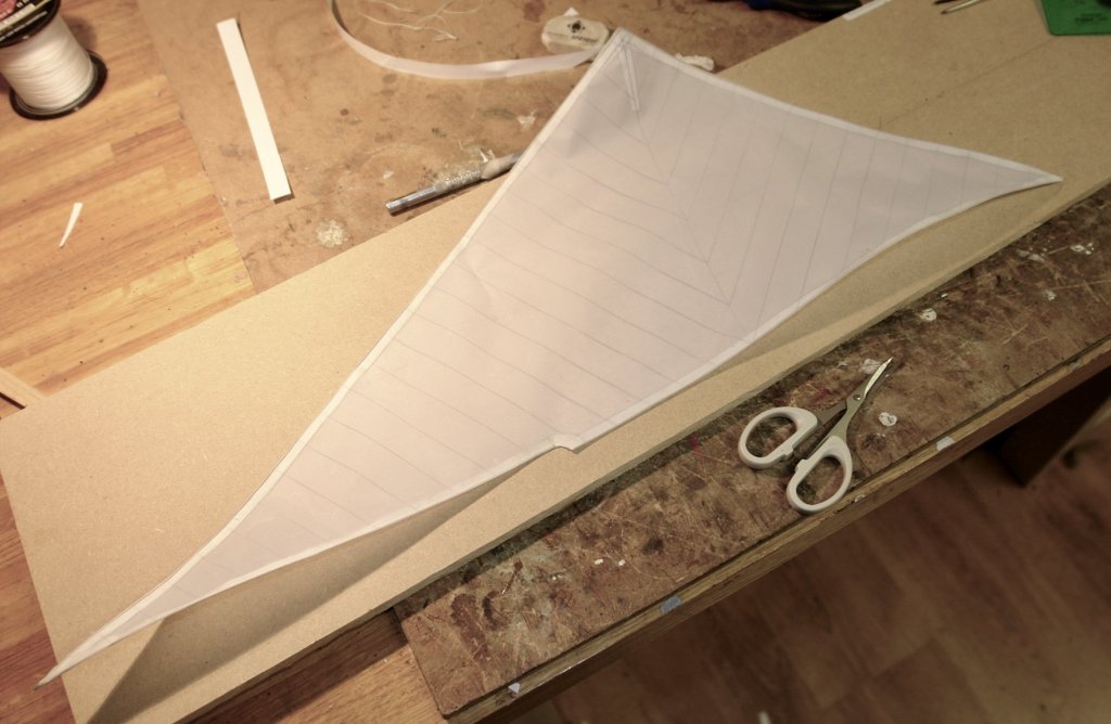
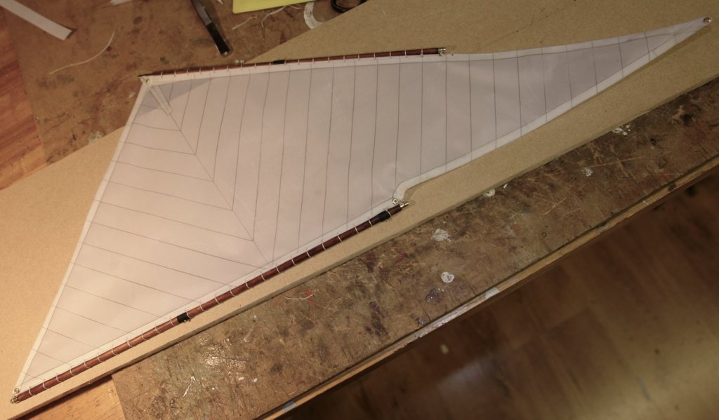
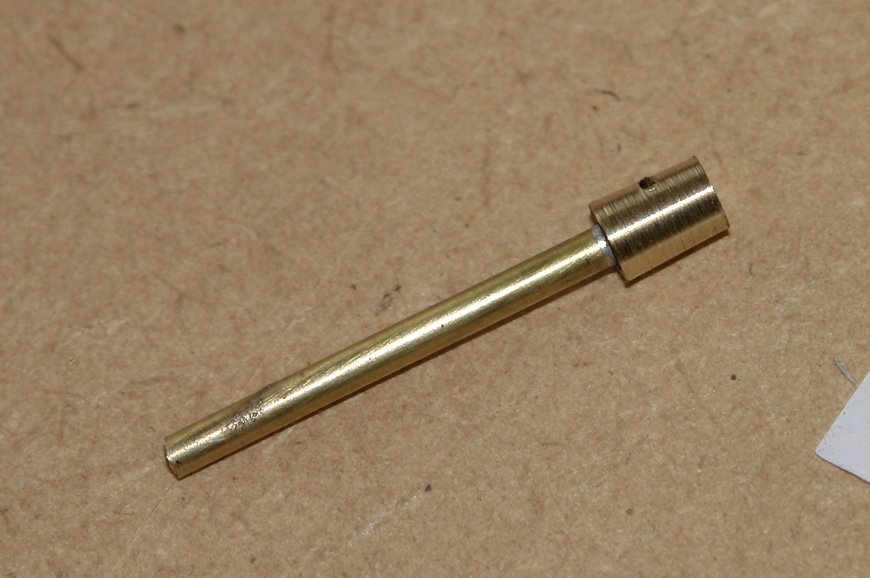
Jon, My commiseration to the turkey but I hope everyone else had a good time. The main topsail was the subject of last nights and todays activity. I started as normal with a template. Basically as per the plans with minor adjustment as a result of offering it up to the topmast. The plans do not show the cutback of the luff to clear the top of the mainmast. As the cutback is clearly visible in the photos I decided to include it. The sail was made on the template with wired edges etc etc - as previously described for other sails. The topsail and jack yards were then attached and the sail spliced on. At the bottom right is my splicing (stitching) aid - the twine is cemented into a small bore tube (.08" OD) and the end is chamfered to a sharp point. The sail is mounted on the topmast secured only at the top by the halliard and at the waist by the sliding ring. The tack is still hanging loose and the sheets are not yet rigged. The Halliard is temporarily secured by forceps - visible in the photos.


- 882 replies
-
- 14
-
-
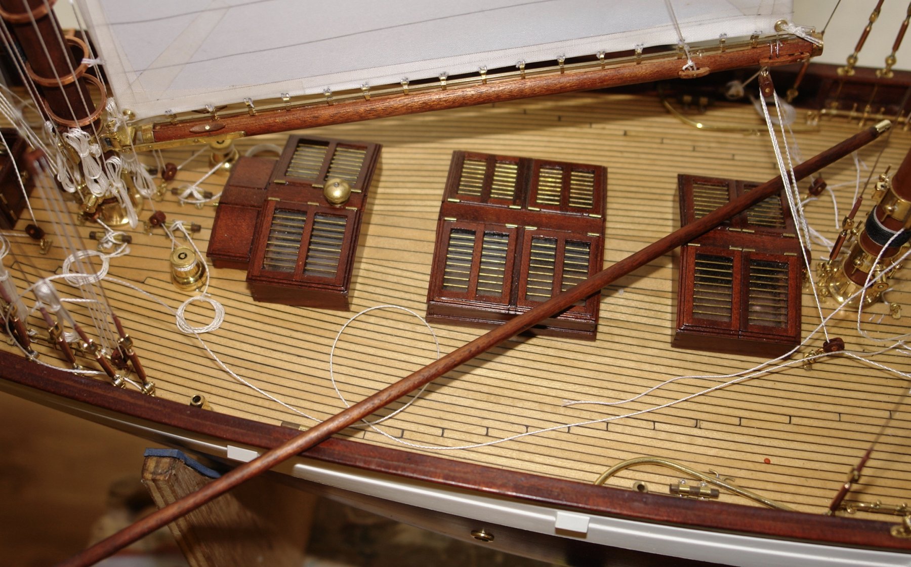
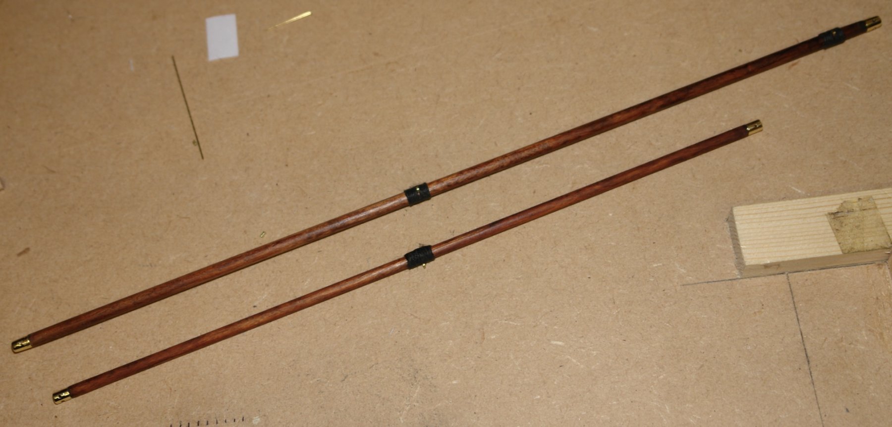
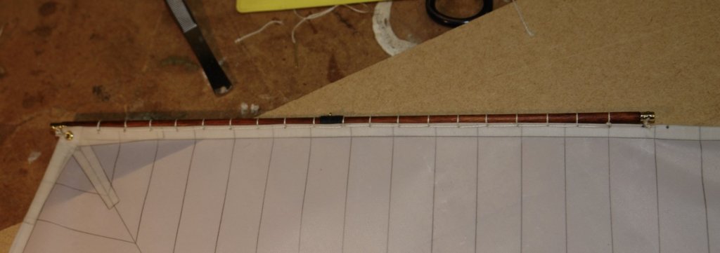
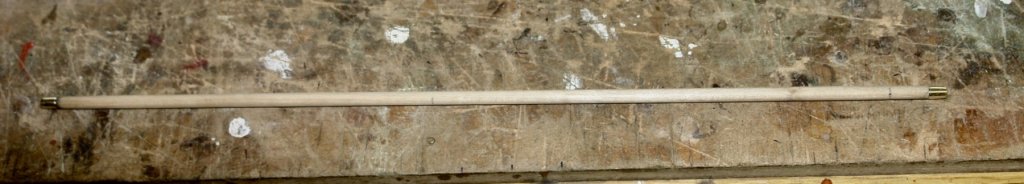
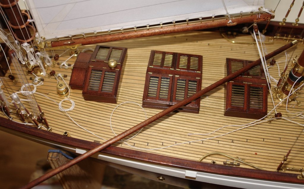
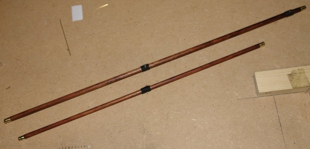
Bedford - thank you for the offer - I'm not sure that the other side of the world is very convenient though. Thank you to everyone else who looked in. MAIN TOPSAIL:- The manufacture of the jack and main topsail yards were not done during my mast making marathon easier in the year. Making them gave me a nice change from sail making and rigging. I didn't have any photographic detail of these items and the plans were quite sparse. I decided to add a little interest in the form of brass end fittings. I had some mahogany dowel from which I intended making them but I realised that it was much too flexible at the desired diameters (jack yard = .190" dia and topsail yard .160" diameter). I did have some .200" ramin dowel that was stiffer but of course the colour was wrong. I decided that the ramin was the best bet in combination with a blend of Walnut and Georgian Mahogany wood dye by Liberon. The yards were sanded to diameter on the lathe. I took the opportunity with the end fittings of extending the mounting spigot to provide additional stiffness, the yards were drilled to take the spigot. The spigots are inserted in the yard and glued in place. You can see the wood colour is far from ideal. However it is wonderful what a bit of dye blending can achieve. The yard is laid over the deck housings to check the colour match. A few eyelets and a bit of binding and the job was done. And so back to sail making.
-
Jon - I also responded in my Altair post. I actually did it slightly differently as I explained in my response.
-
Nils Nice detail of the stoves internal brickwork.
- 692 replies
-
- 6
-
-
- eagle of algier
- chebec
- (and 2 more)
-
Thank you John & John. Still some way to go before it is finished and a few significant items to make. I think I need to write a list and systematically work through it. My wife advises that all lists should start with jobs already done. Apparently that way you can immediately cross them out, feel good and celebrate with a cup of tea. Michael, welcome back and thank you. Have you been on vacation? You are so right. I have to say that I have sadly neglected my epoxy filler skills of late. A white painted hull would certainly give me plenty of opportunity to wack on the epoxy and get out the 60 grit paper.
-
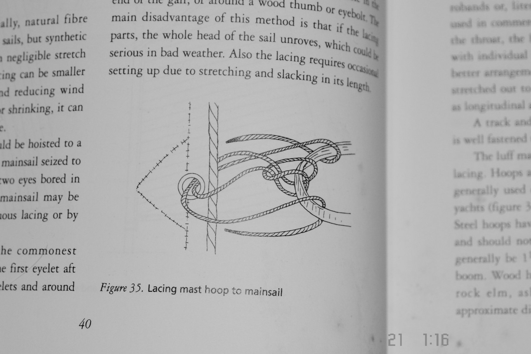
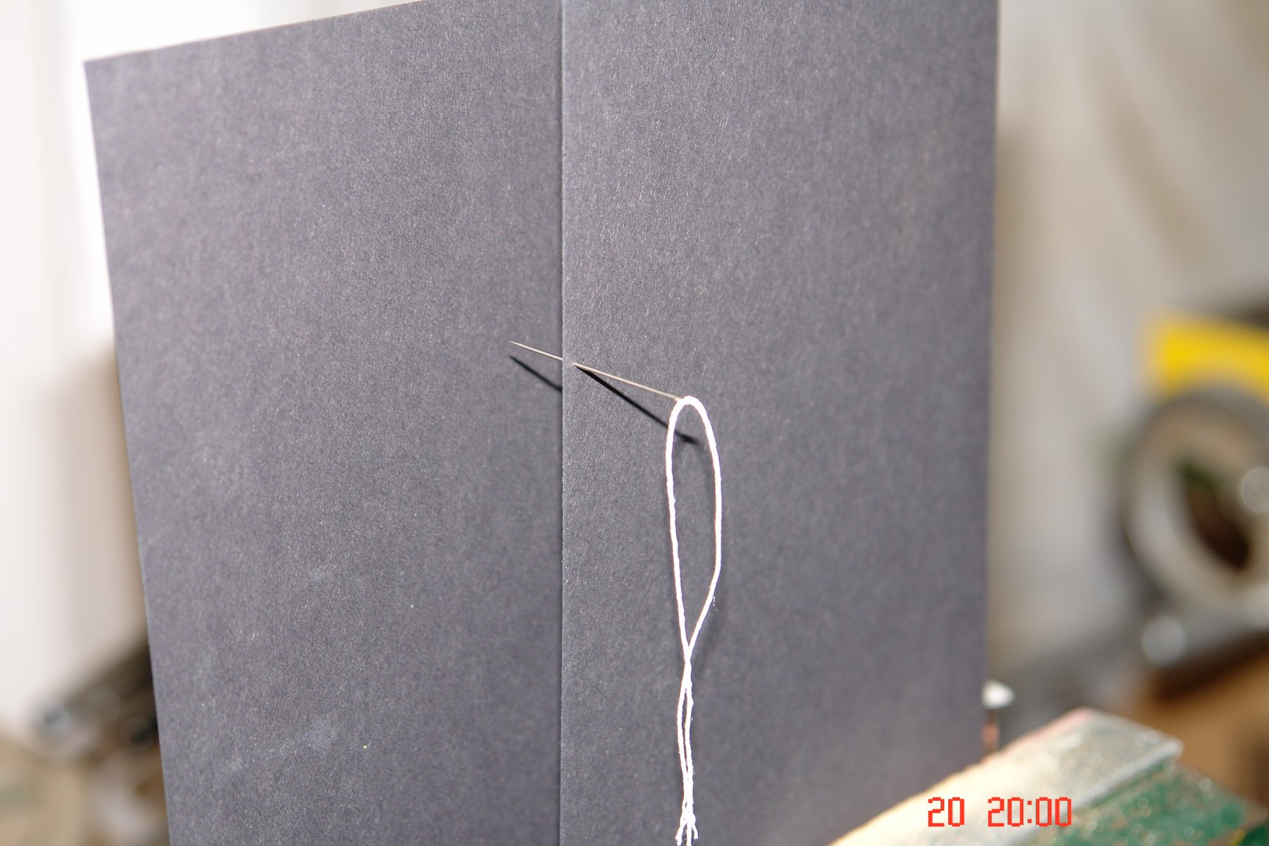
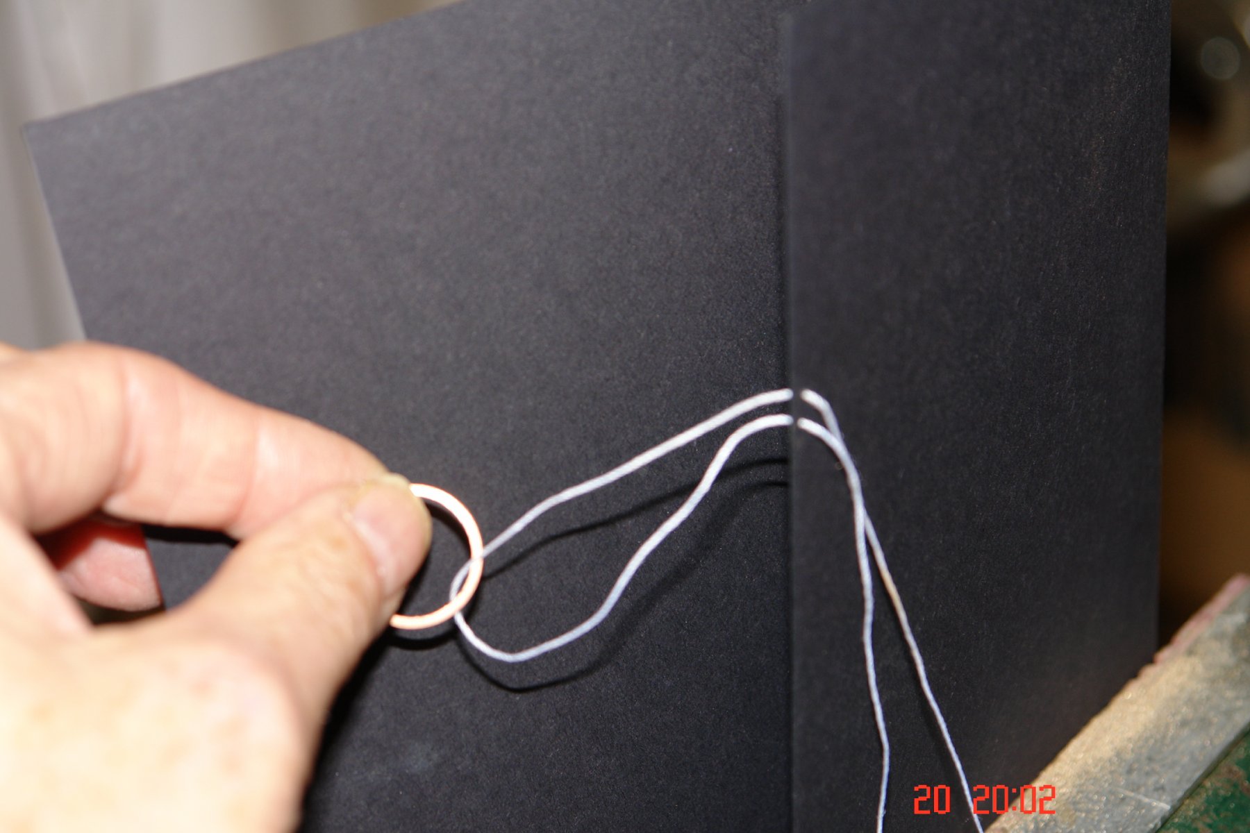
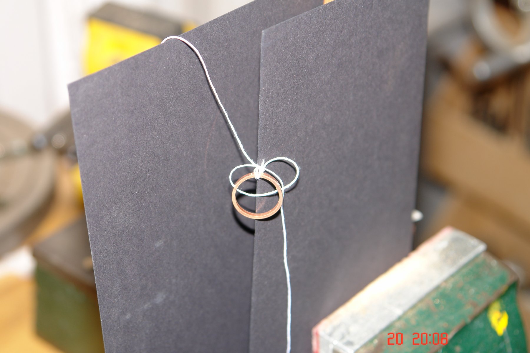
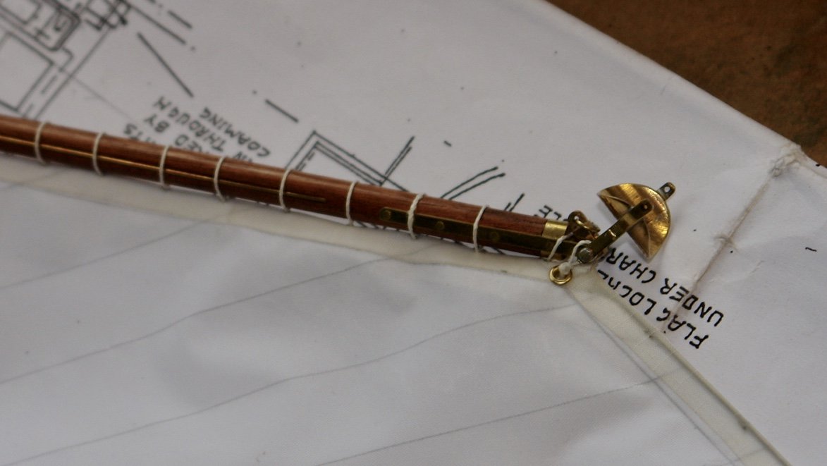
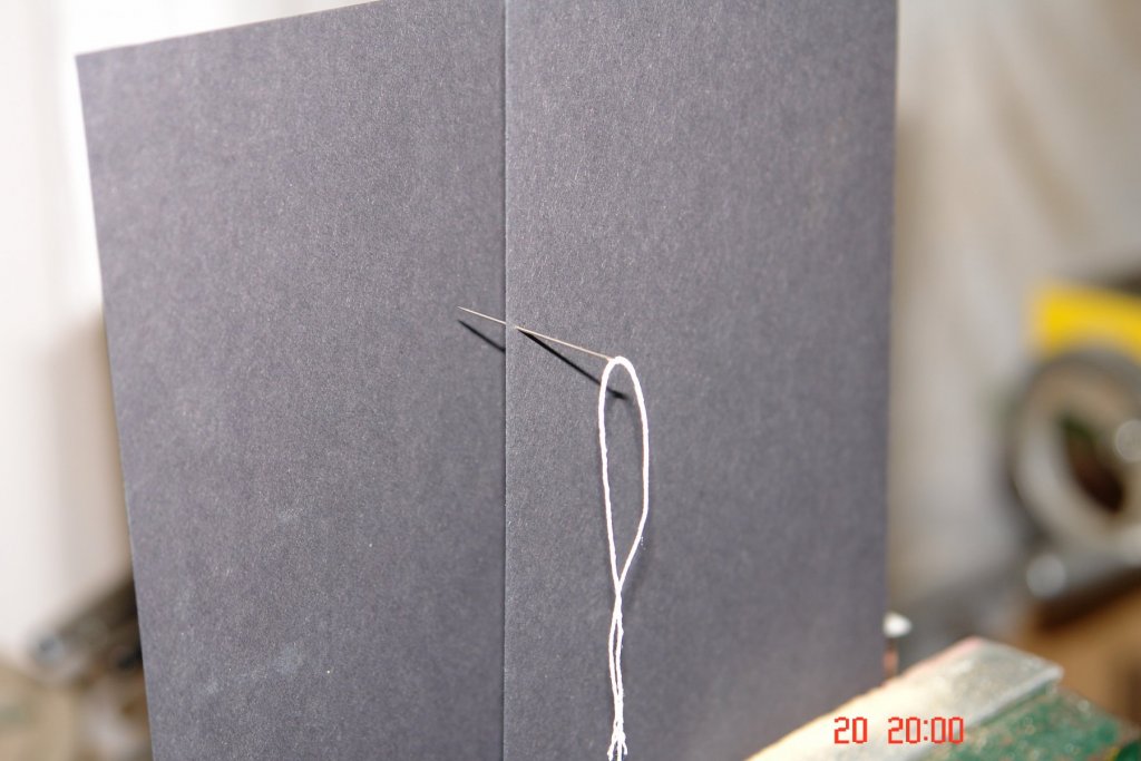
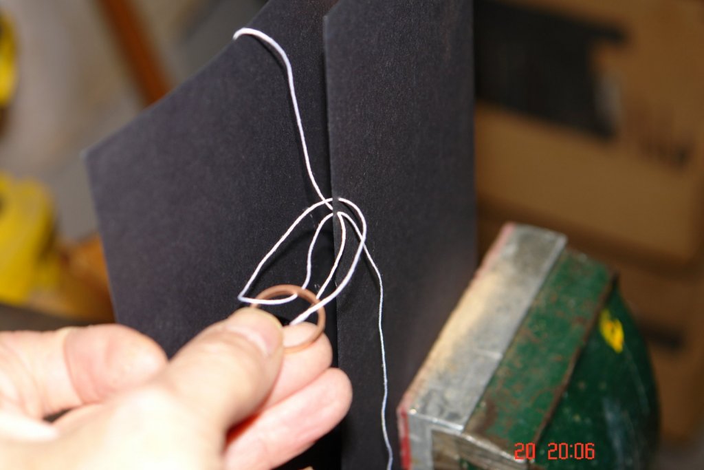
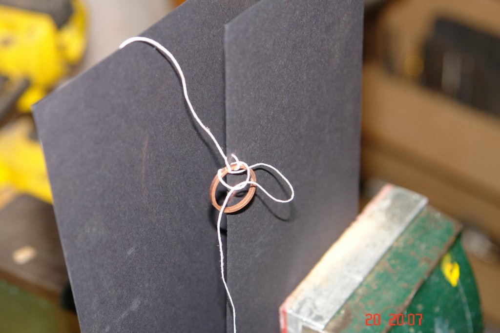
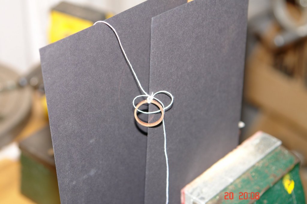
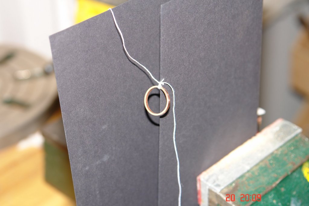
Jon. Not sure of the authenticity of this way of doing it - but it gave the look I was after:- Then taking one of the tails knot it round the 4 threads between the ring and the sail edge - And again to lock it. Then the same with the other tail from the opposite side. Then a dab of CA glue.

-
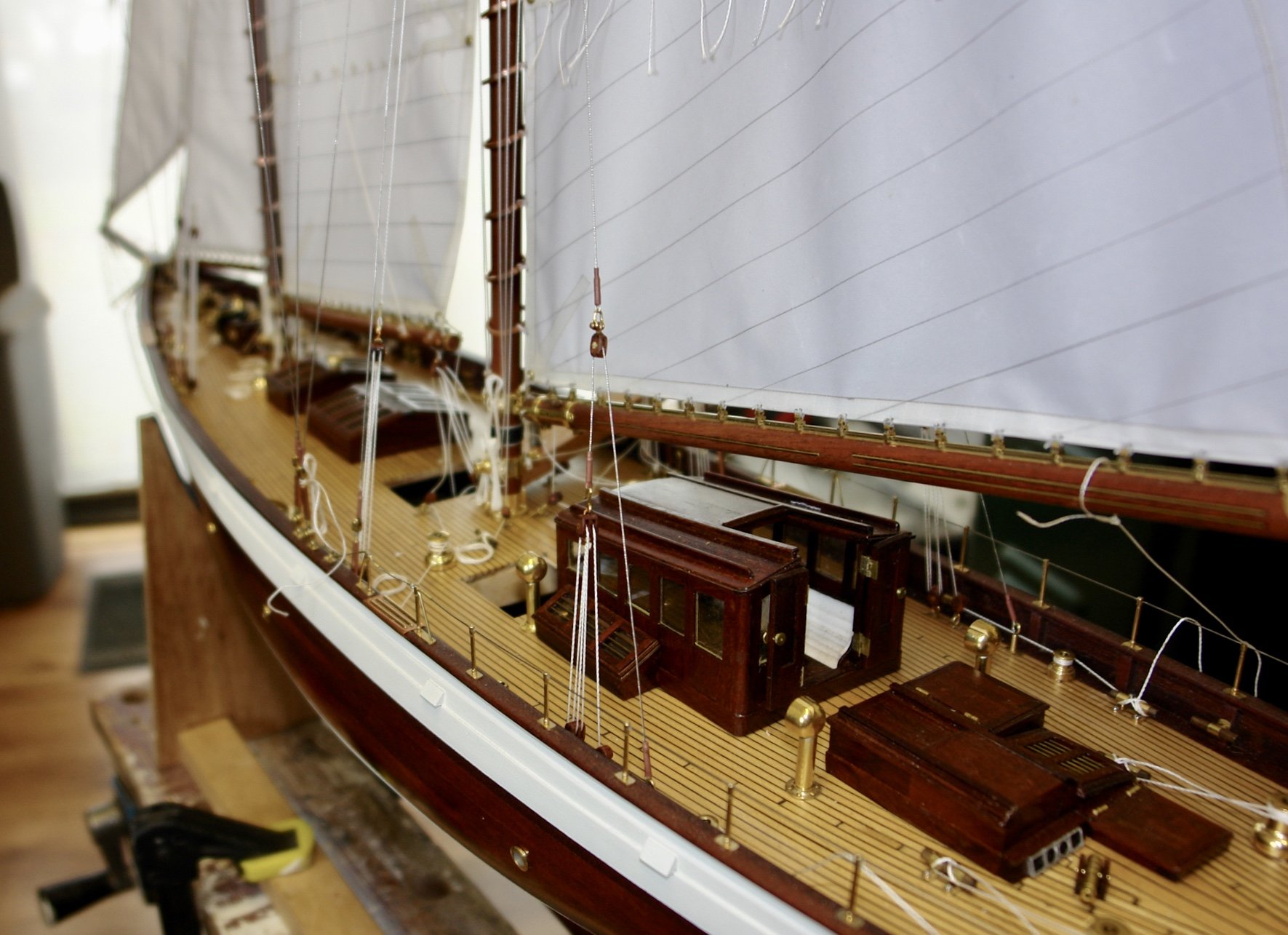
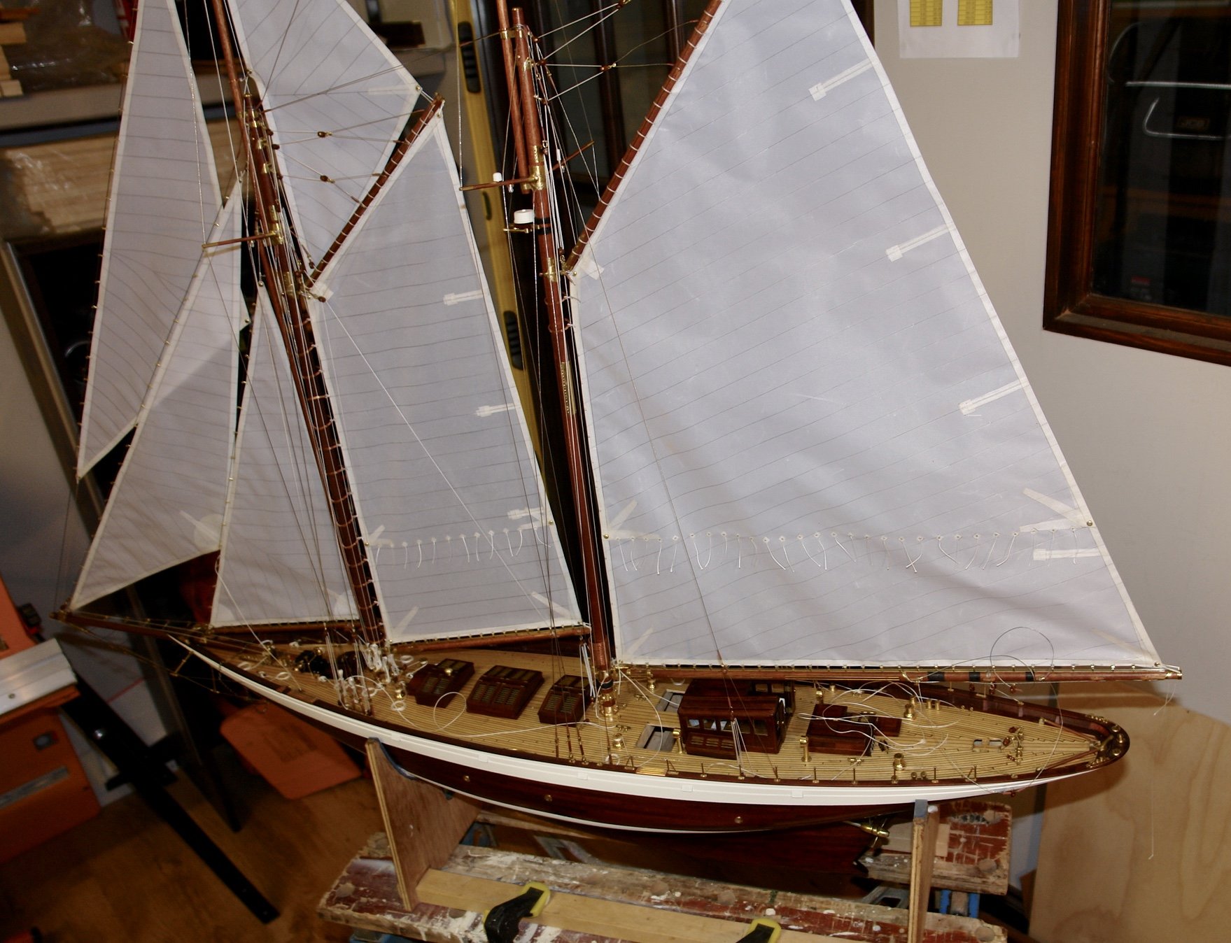
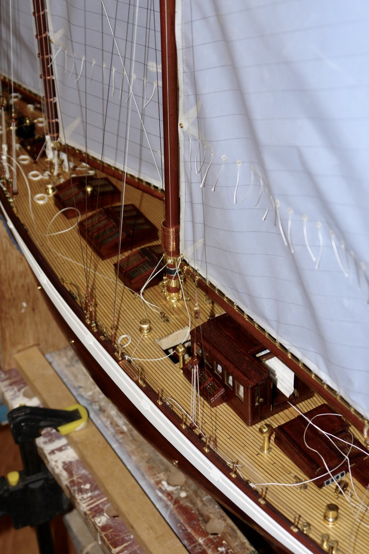
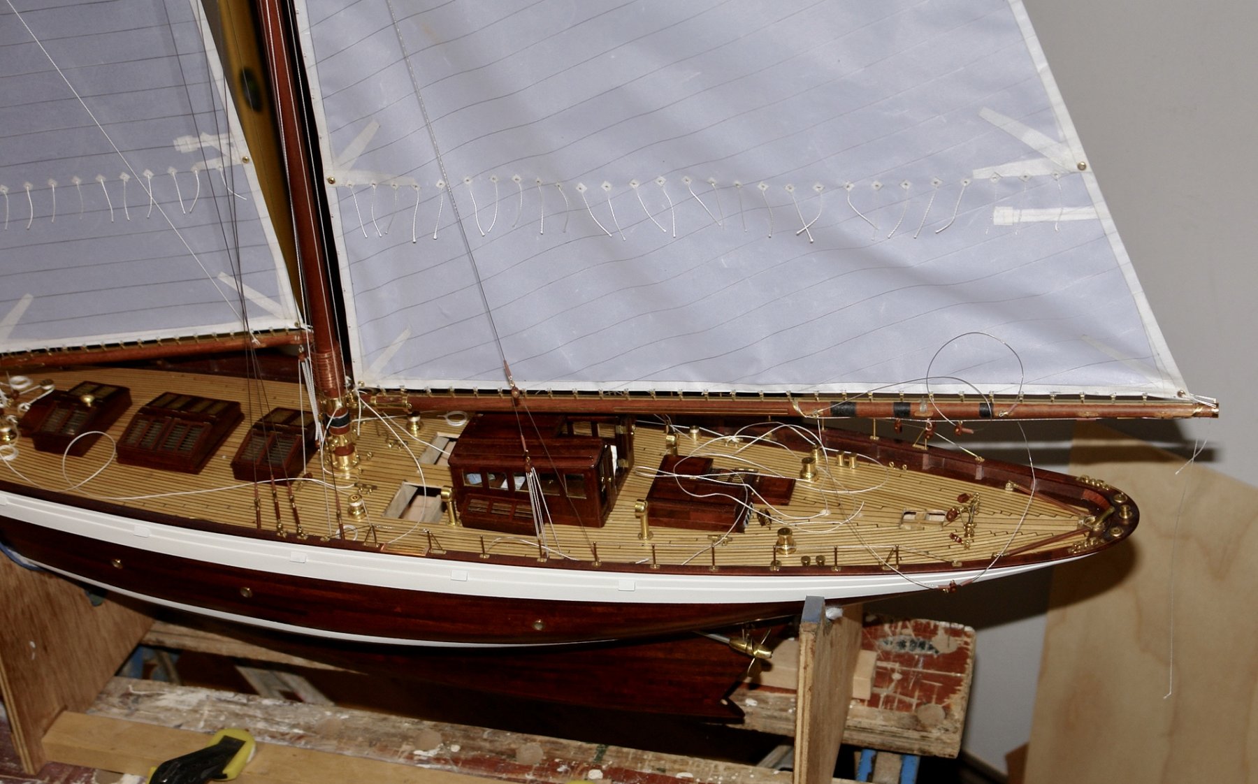
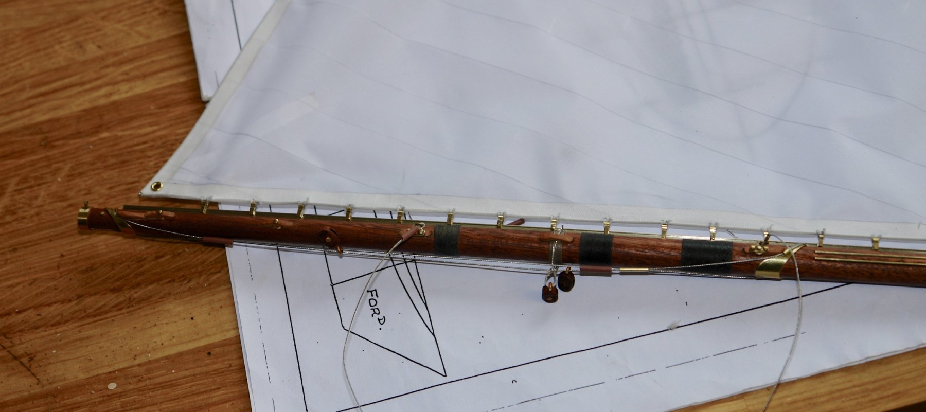
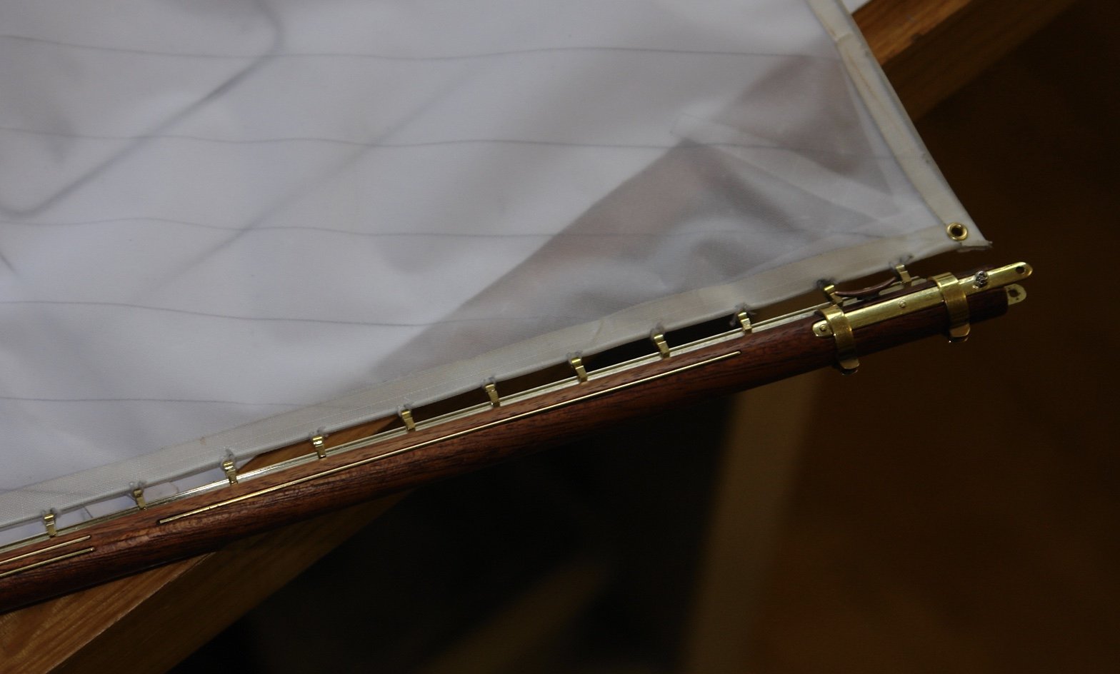
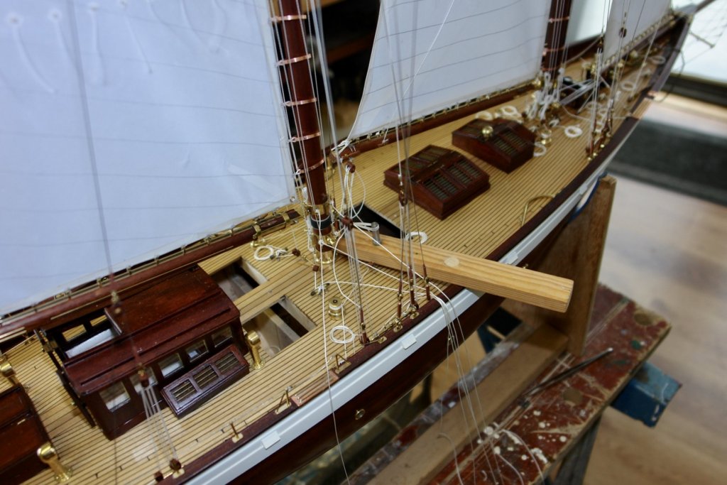
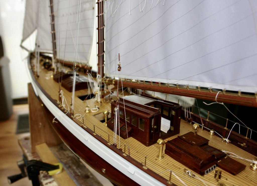
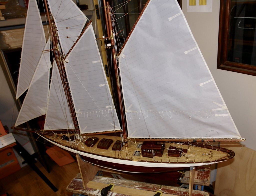
I have partially completed hoisting the mainsail. It was quite tricky and needed more than 2 hands. After struggling for a while I gave in an invited my wife to help. There followed a tense period of instruction but fortunately no divorce. I find that I need to get the sails up with the halyards quite loose, and then progressively tighten them as I complete the sail hoop attachment. The photographs are taken at the stage of the 2nd hoop attachment with the sail still without any real tension. Fortunately I remembered to install the deckhouse, it does not go in with the boom installed. Anyway here are the photos:-


-
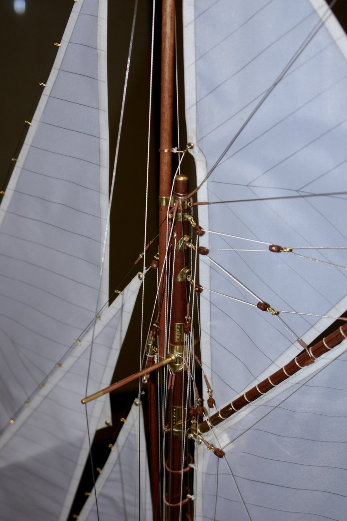
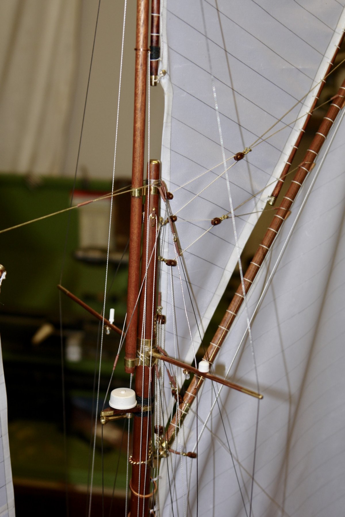
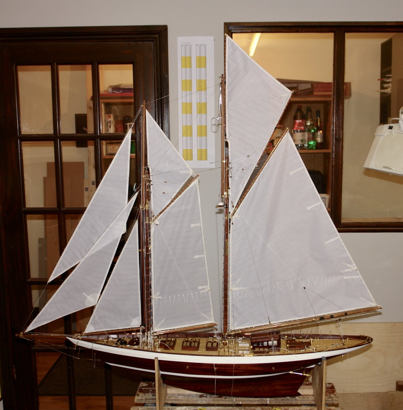
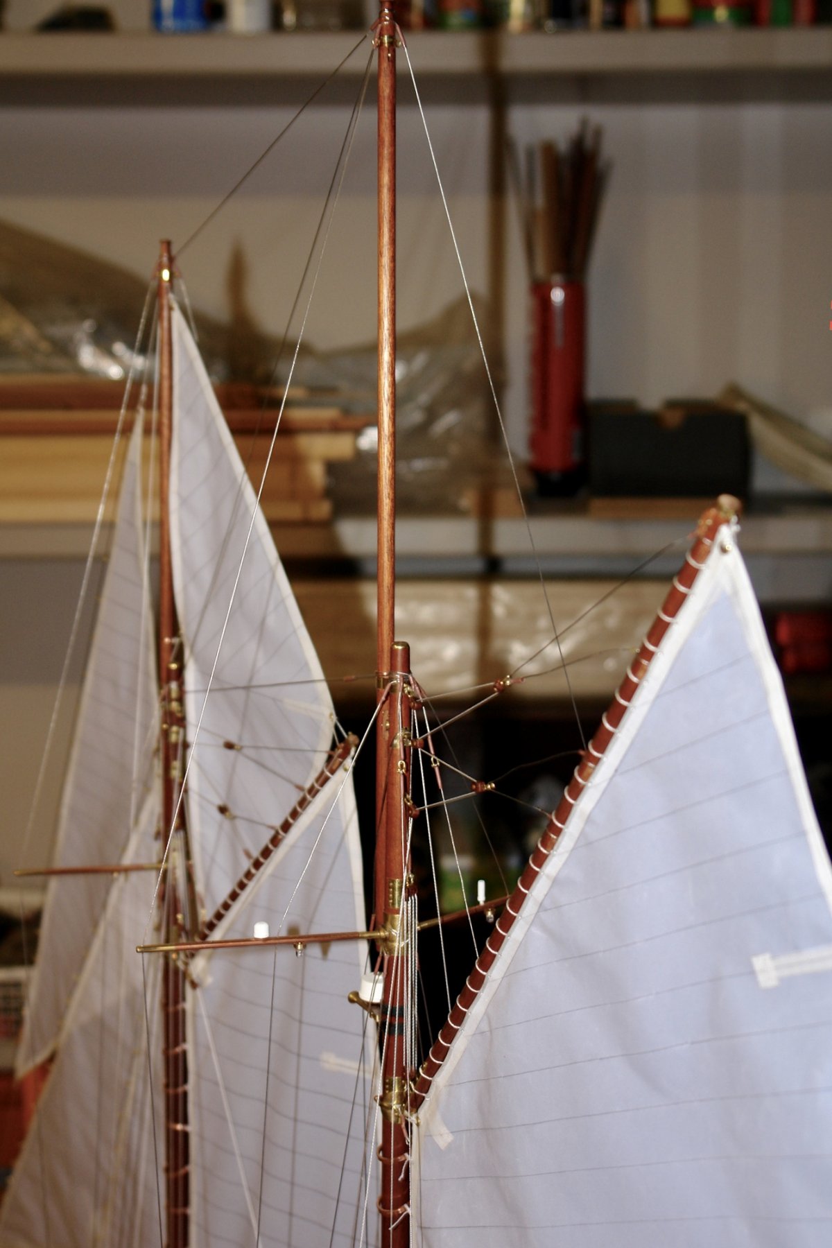
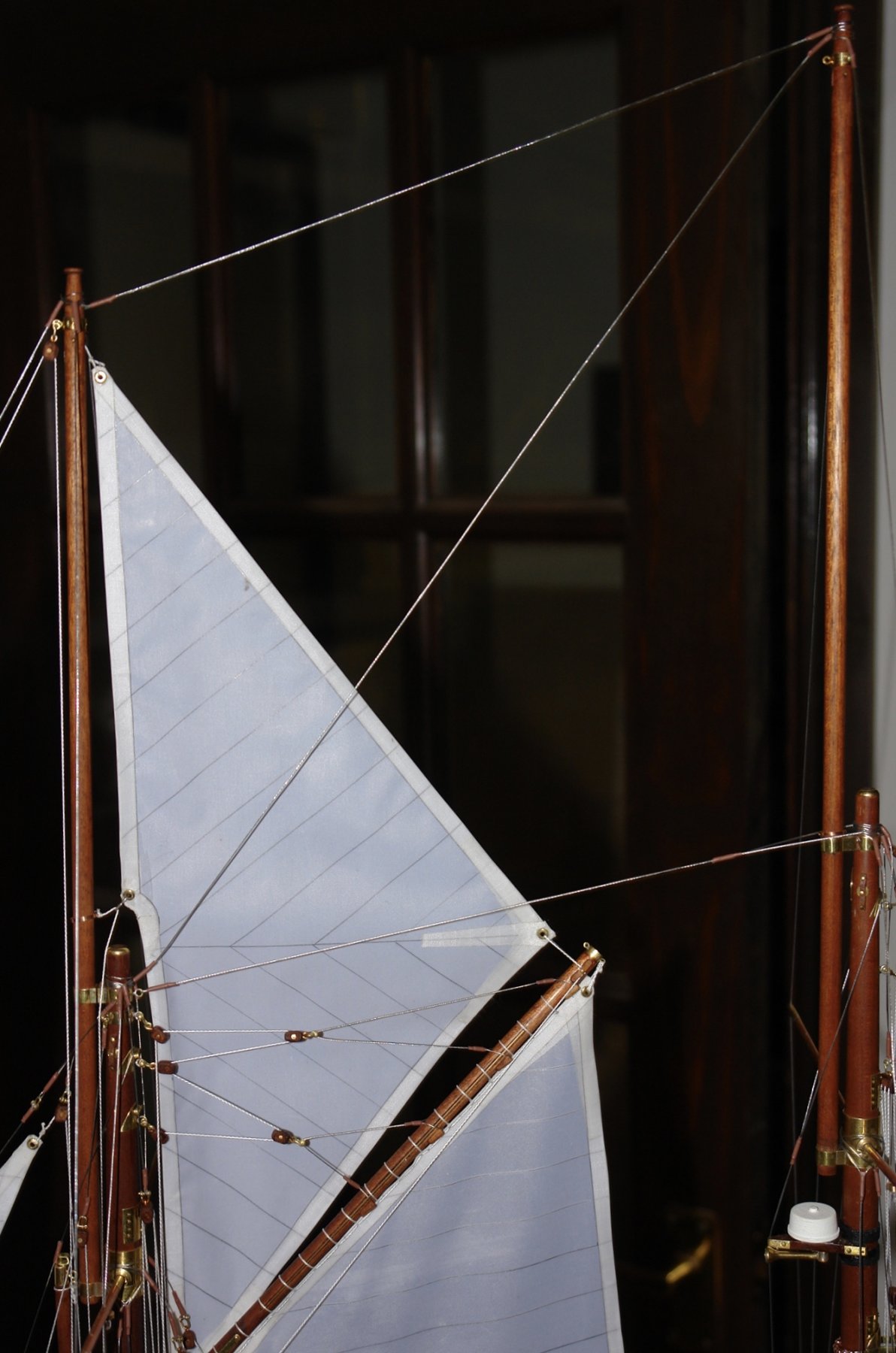
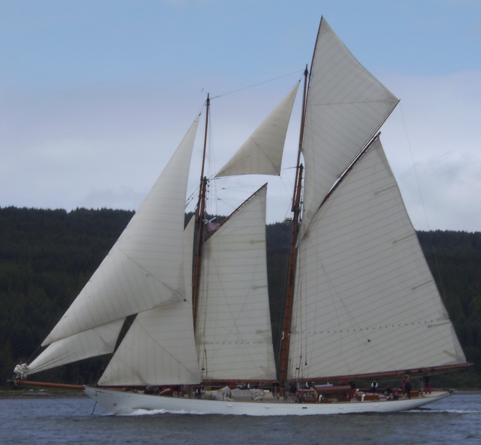
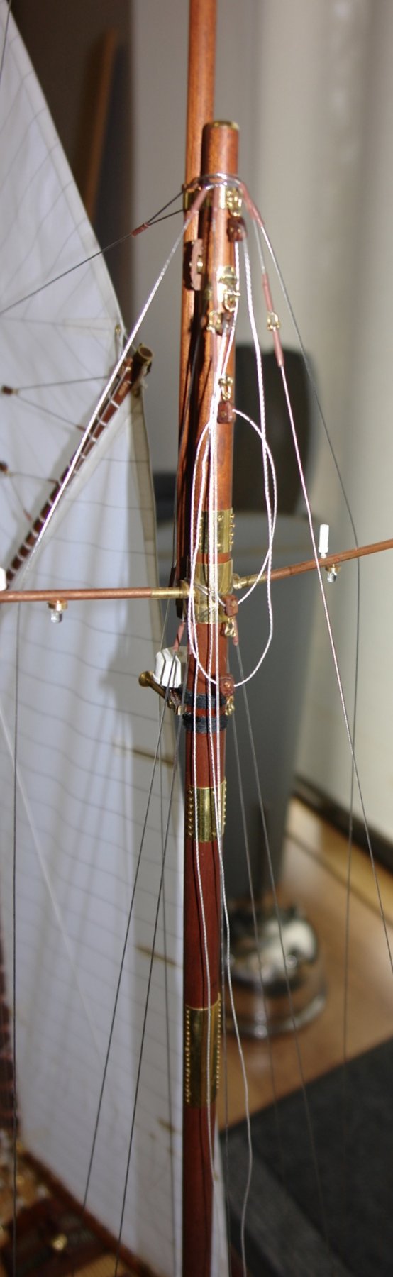
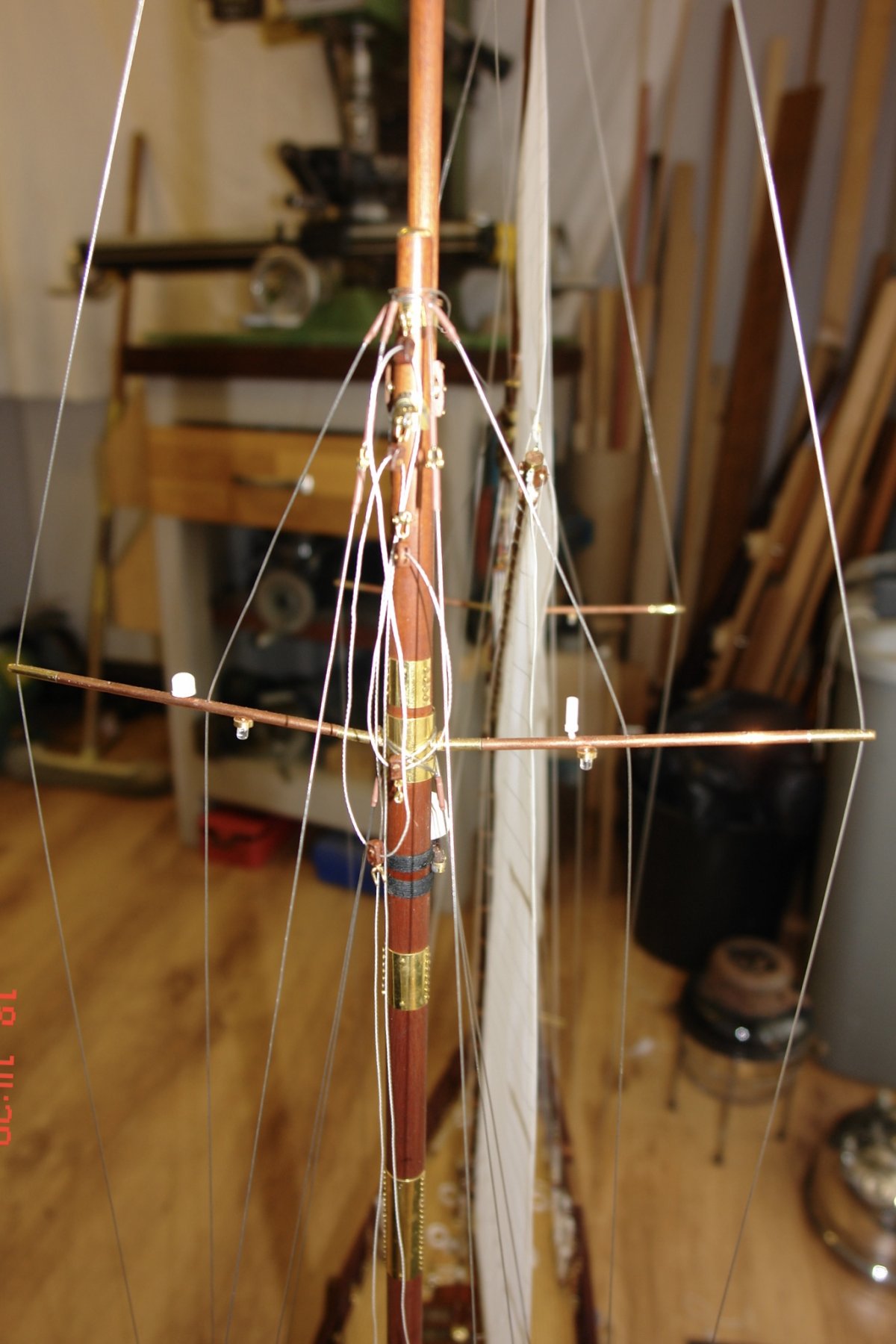
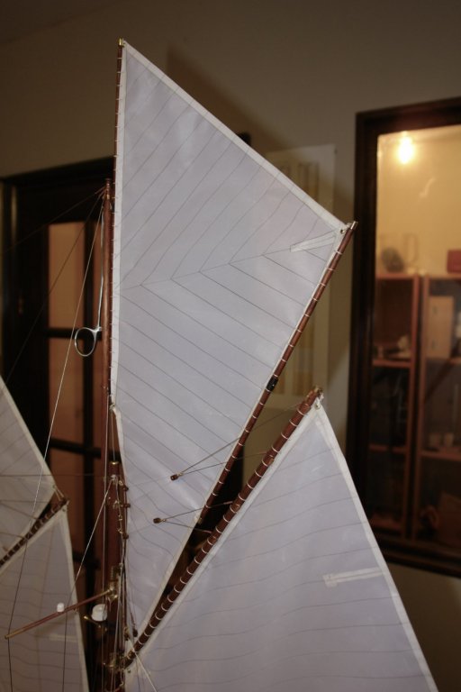
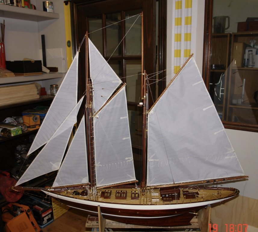
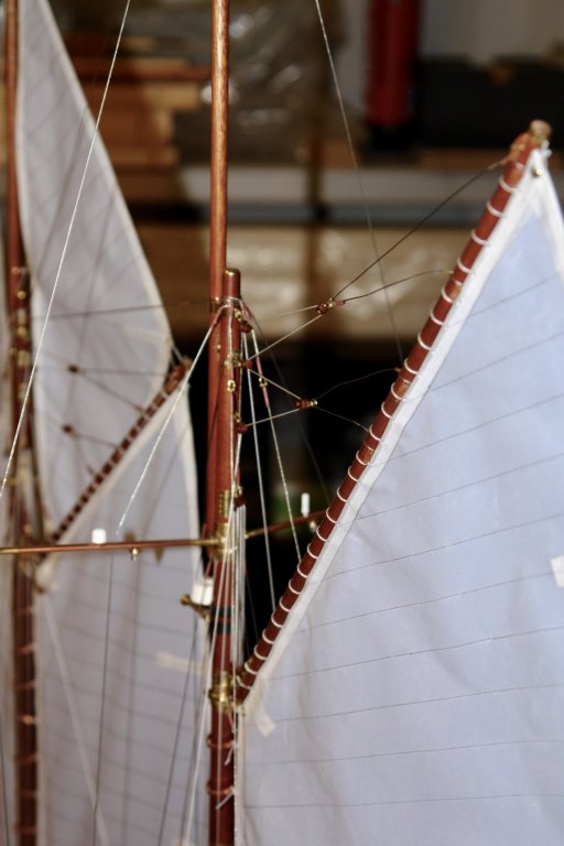
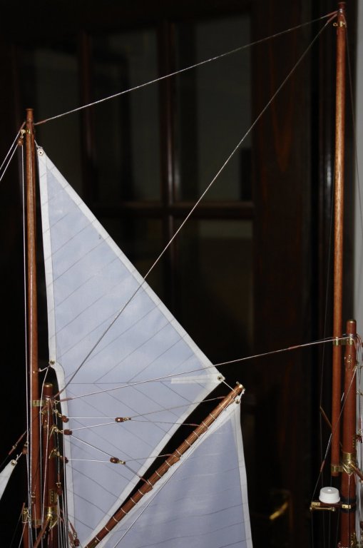
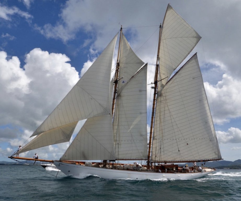
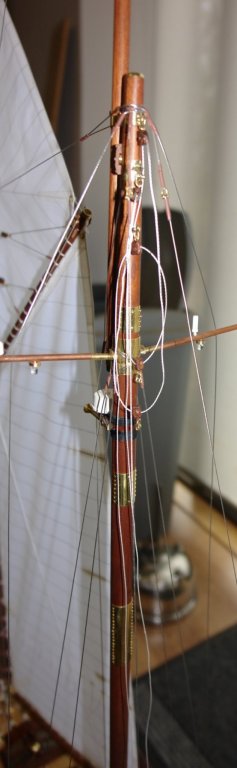
Bedford, thank you for looking in and for the information. I will find a use for it somewhere but unfortunately it does not quite resolve my lack of understanding. I probably should have explained the issue better - here goes. The picture below shows the topsail rigging arrangement. Tacking the sail without taking it down would involve passing the foot through the triangle made by the fore topmast, the spring stay (top) and the mainstay (diagonal). As most of the sail sits below the mainstay the action of the wind would be to hold the sail against the mainstay and the triatic, rather than blowing it through the upper triangle. I have a number of pictures of the yacht rigged with just a small triangular sail (see photo) which sits in the space between the mainstay, triatic and the main topmast. I think they must do this to avoid the complexity of tacking the larger fore topsail. To complete the picture the photo below is Altair rigged as I am building her. (edit - except for the jibs / foresail which are as the previous picture.)

-
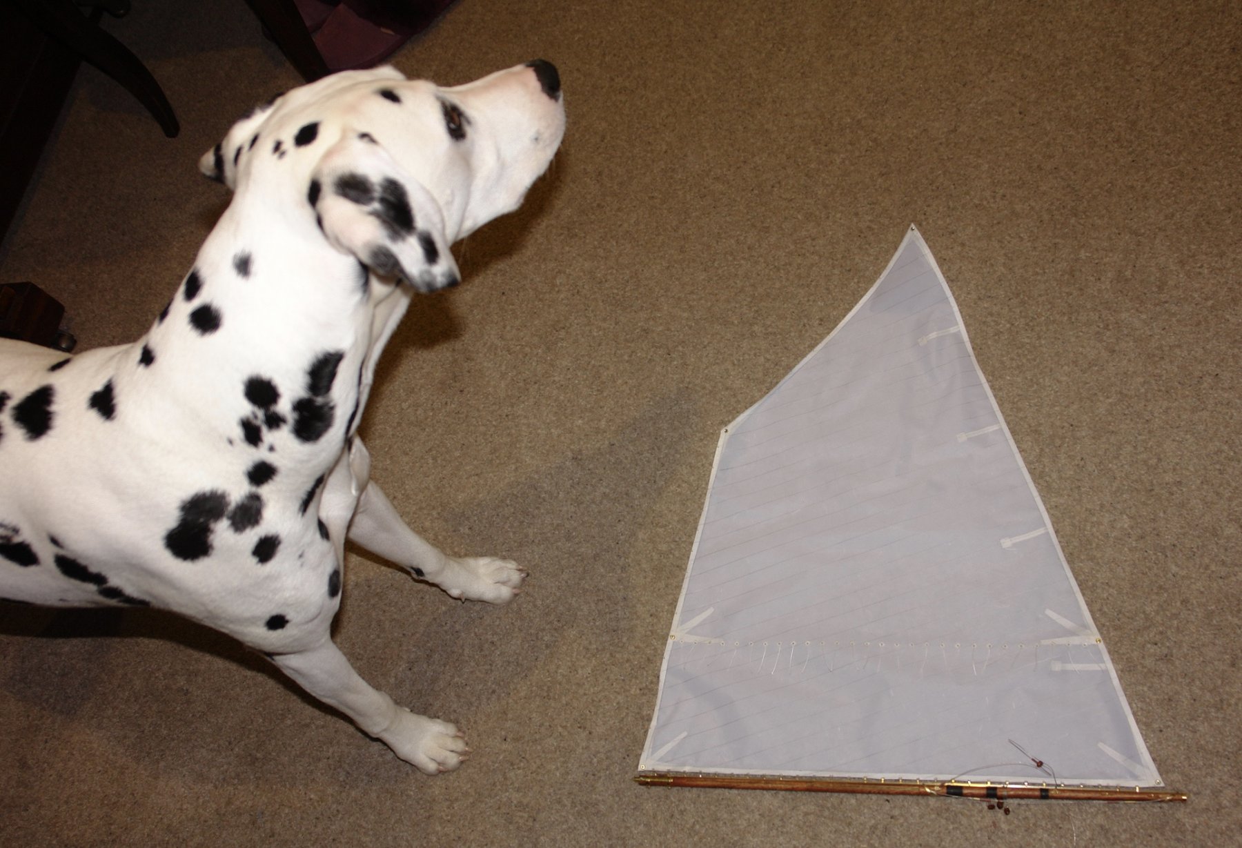
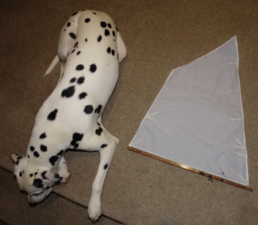
Seeming, Sewing and Stopping:- I moved on to the mainsail, a virtual repeat of the foresail. That said I had awful trouble getting the cloth reasonably flat. It was a new piece of cloth that, on application of the PVA wash, bagged and bellied in a most unusual fashion. Whether the fault lay with me or the cloth I do not know. In the end I had it pinned to preparation frame at multiple points while it dried. It seemed to work but time will tell. I won't go into the long process of building the sail and attaching it to the boom and gaff but here are a few photos. I was admiring my work while it lay on the lounge floor when a critic turned up to assess my performance. She was obviously unimpressed. I completed all the mainsail related blocks - a full days work and started to rig the mast ready to take the sail. Tomorrow I hope to get the sail up so by tomorrow evening I should have something more interesting to show.


-
ancre La Salamandre by tadheus - 1:24
KeithAug replied to tadheus's topic in - Build logs for subjects built 1751 - 1800
Pawel, nice to see you back on the build.