KeithAug
-
Posts
3,986 -
Joined
-
Last visited
Content Type
Profiles
Forums
Gallery
Events
Everything posted by KeithAug
-
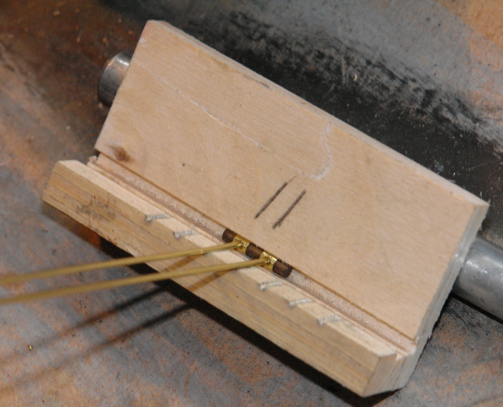
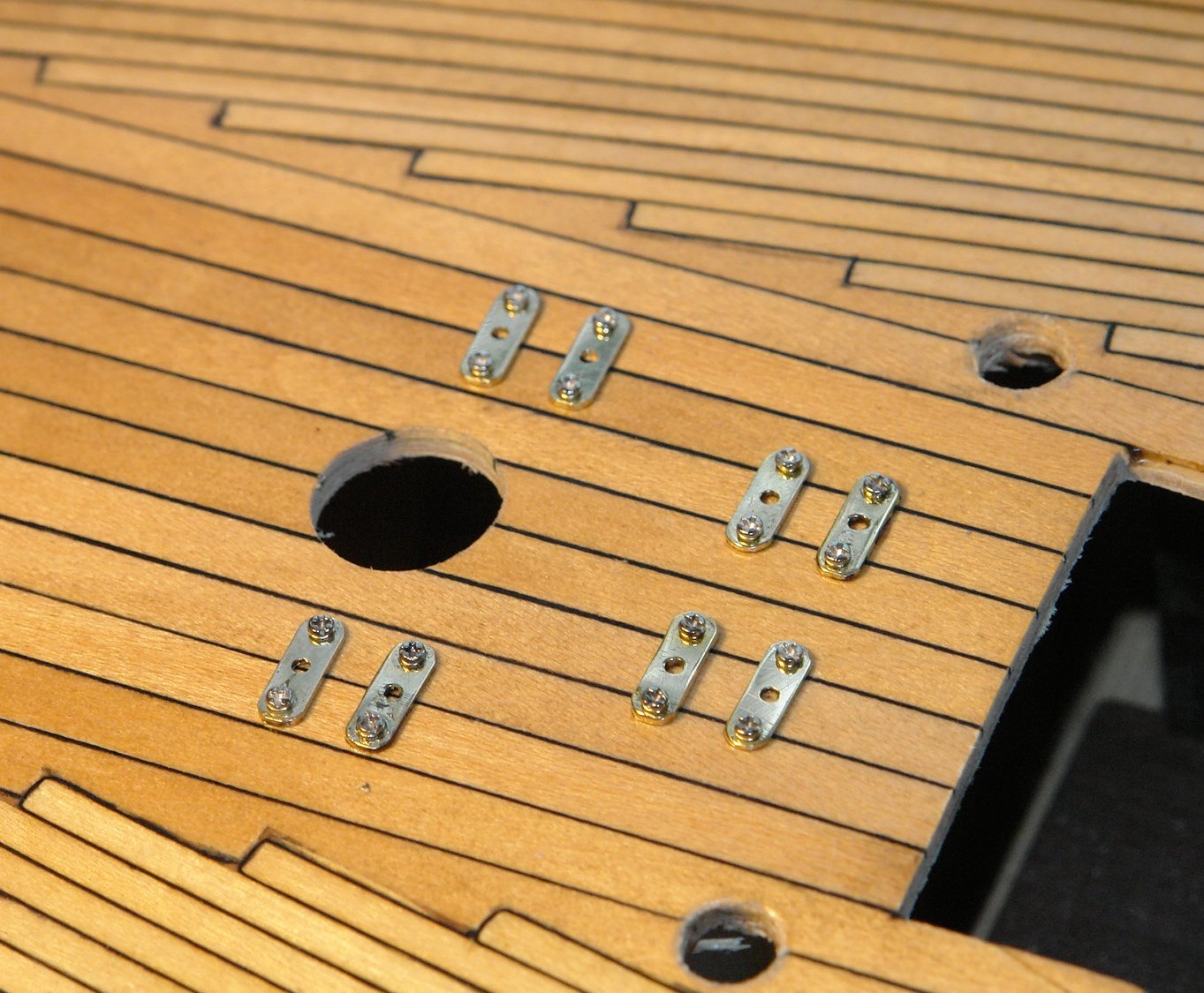
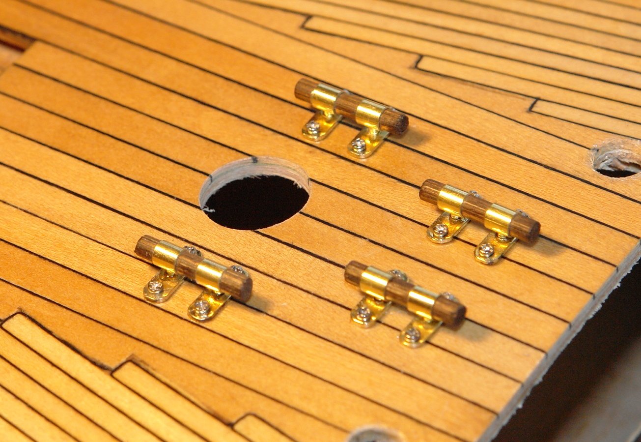
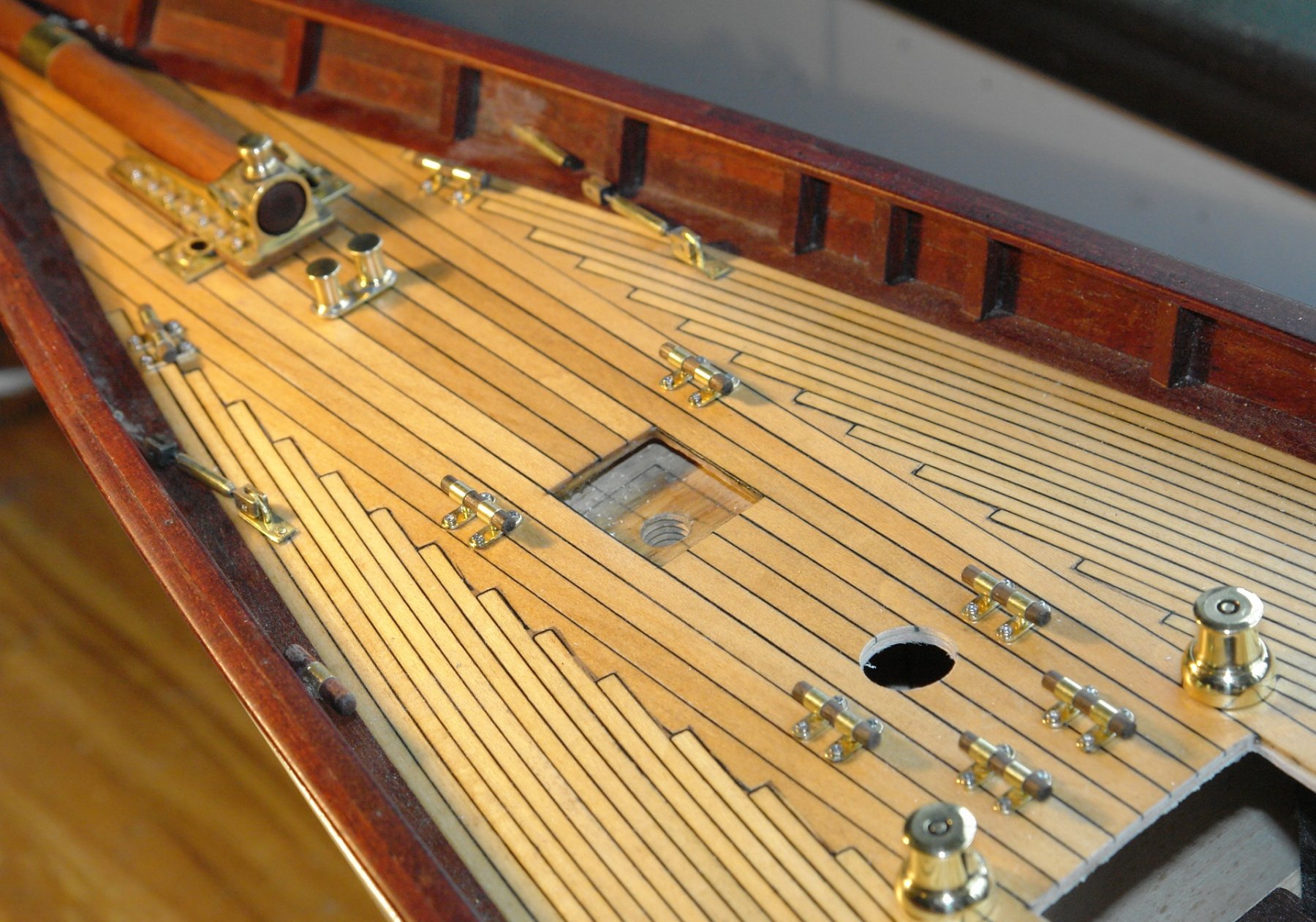
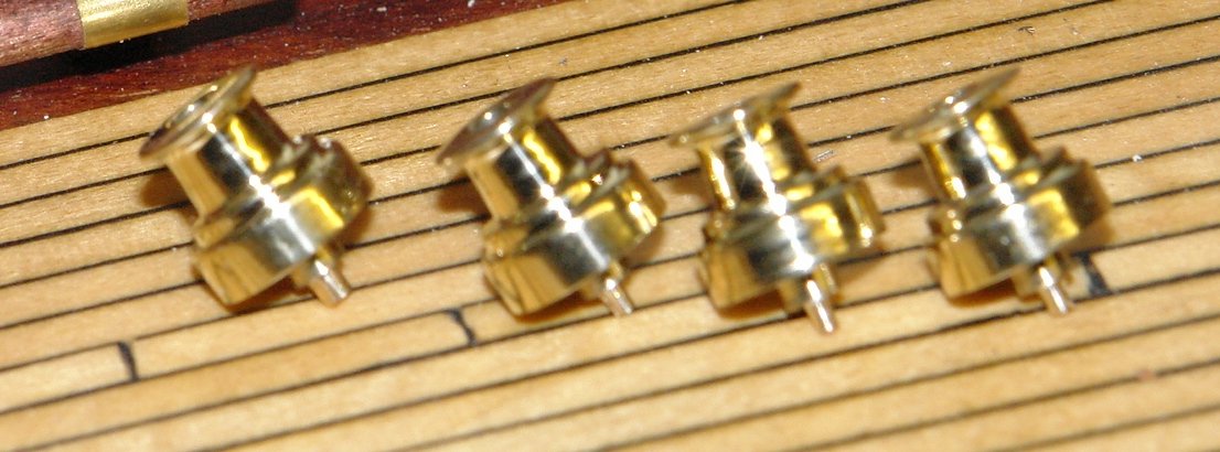
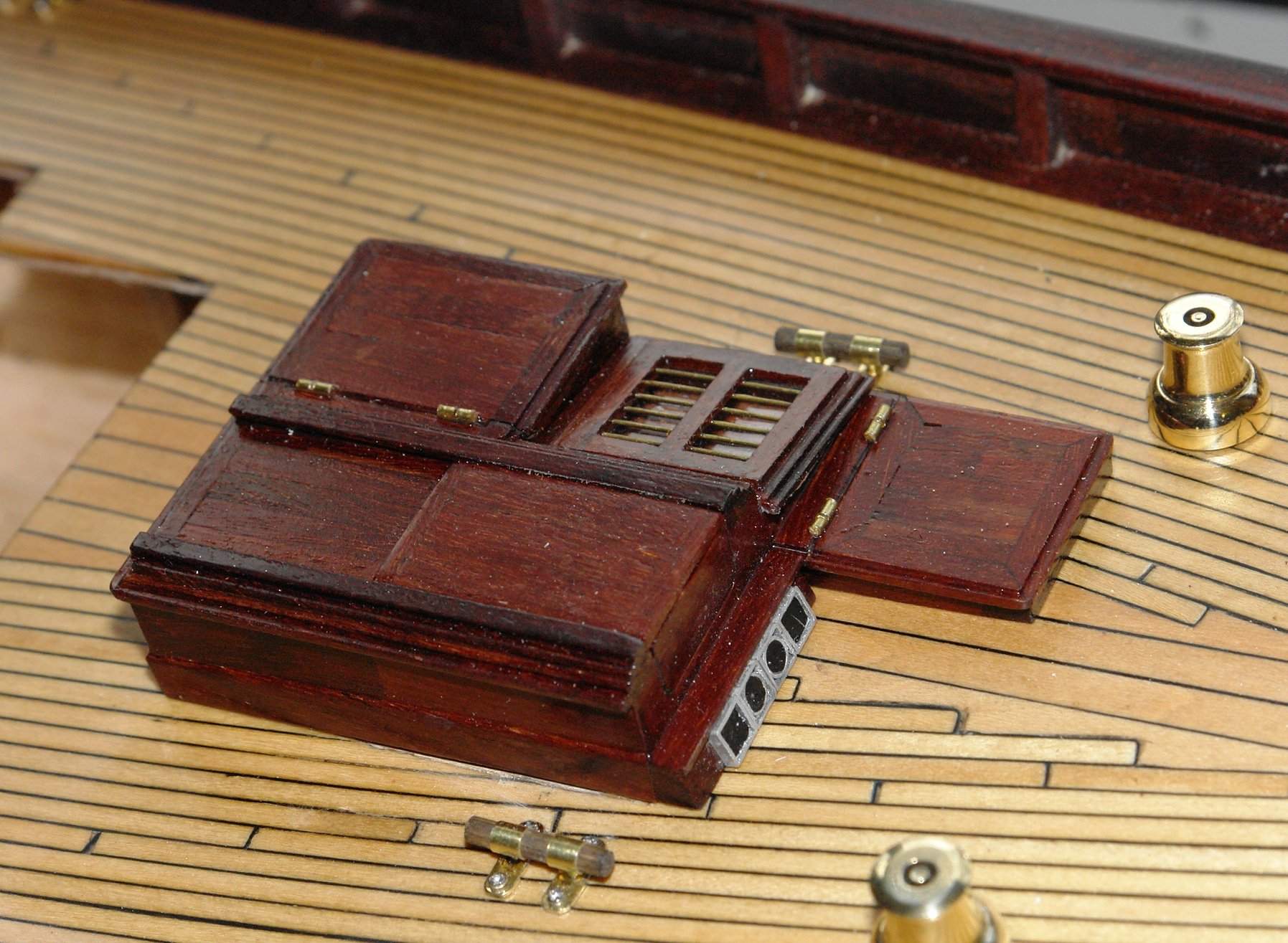
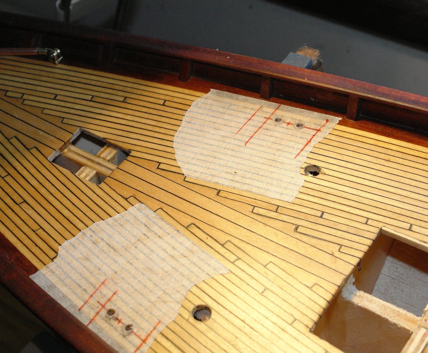
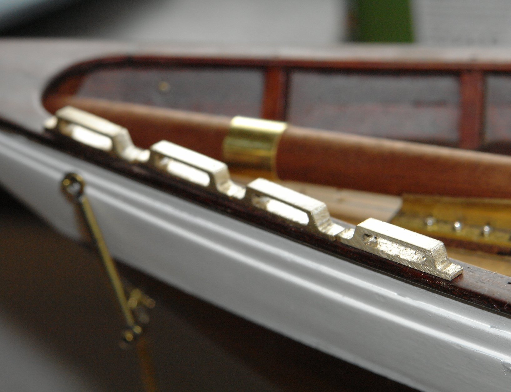
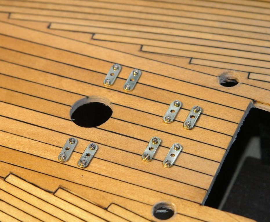
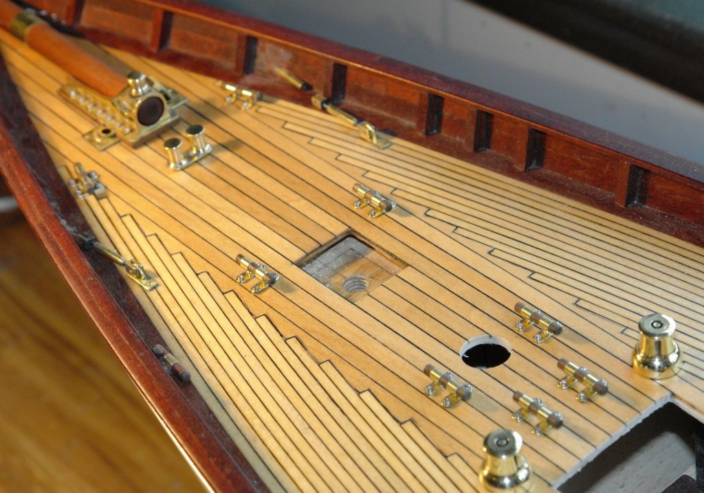
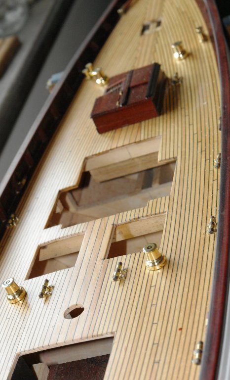
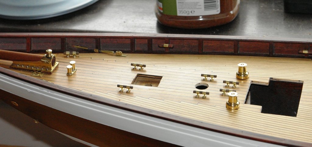
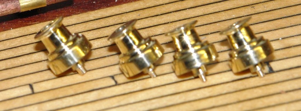
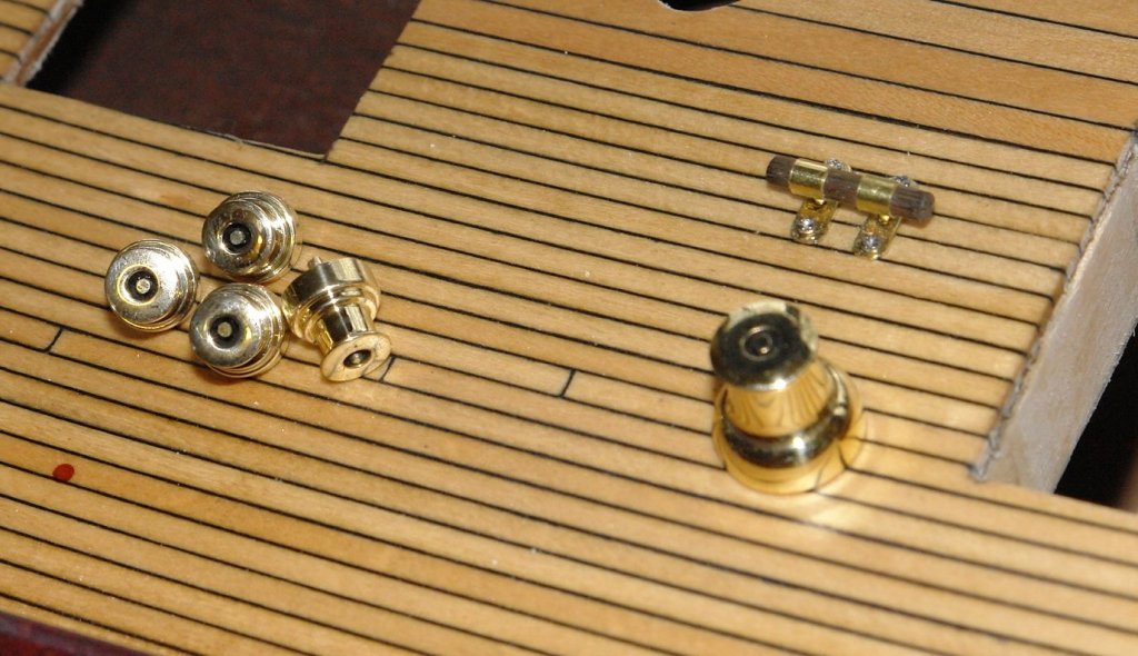
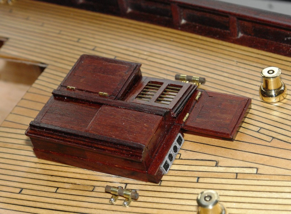
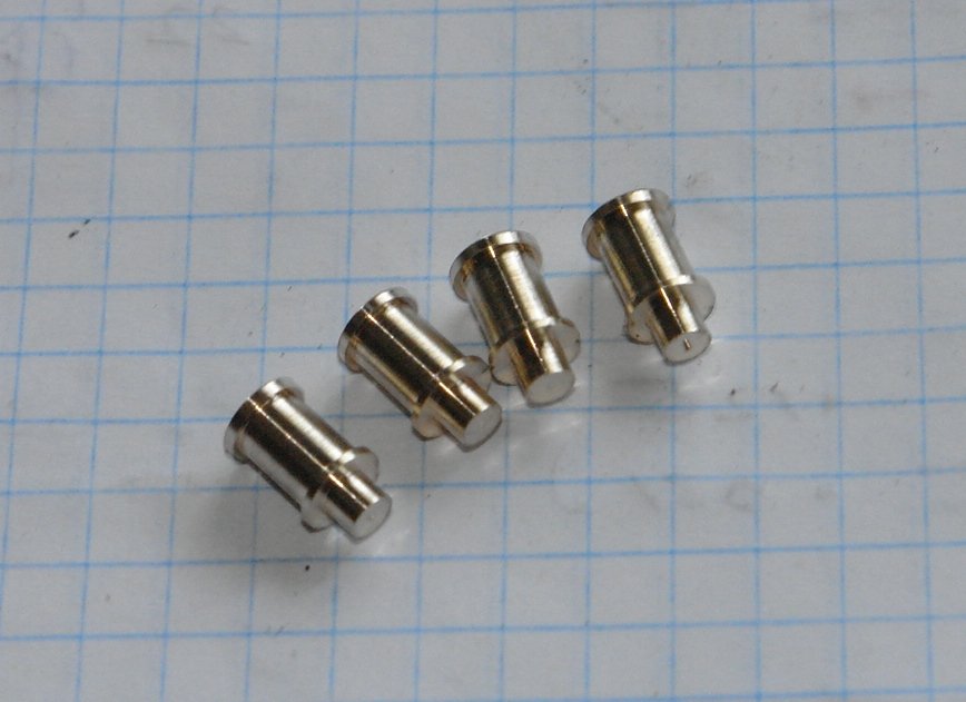
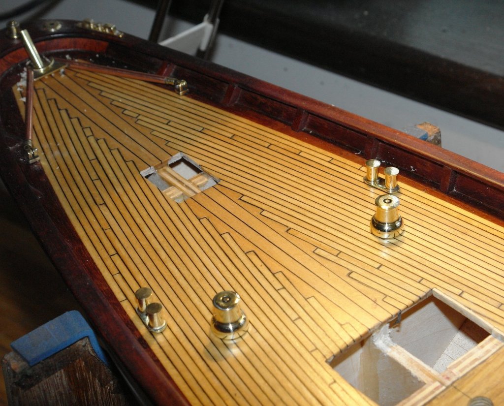
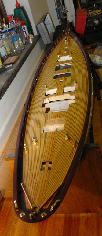
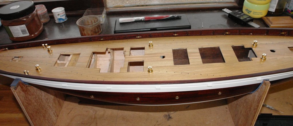
 Thank you Michael and welcome to all other visitors. After a bit of time away I got back to finishing the cleats - now all done. In the end I decided to simplify the construction by eliminating the stem tube spacer - see earlier post. I used a simple jig to make sure that the pins went in at right angles to the top. The pins were glued in place using CA. The feet were attached to the deck first. The hold down bolts are from a spectacle repair kit - hundreds of very small size screws for a few pounds - ebay. I drilled a thin sheet of steel to create a template for drilling the deck. The central holes in the foot were drilled through to the deck to take the tops. A few more shots of the deck:- Having completed the cleats I made the 4 secondary winches. As I think I said previously these are omitted in error from the plans but are very clear on web based photographs / videos. The winches are .325 max diameter x .300 high.
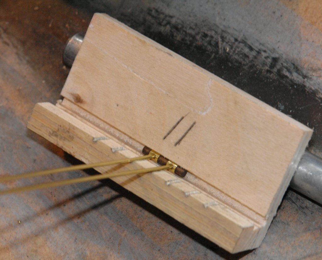


- 882 replies
-
- 17
-

-
Michel, it must be your age. We youngsters find the digital age a delight (so long as the batteries last!
-
Very nice Michael Have you considered butchering some cheap digital callipers rather than using the dial gauges. I used to use dial gauges on the lathe longitudinal travel until I took the step of of bolting on a digital calliper. I wouldn't go back to a dial gauge now. Sorry you are under the weather and hope you get well soon.
-
Kat The attached is a good quick guide to wood choice. http://modelshipworldforum.com/ship-model-materials-and-tools.php Or alternatively try. http://modelshipbuilder.com/page.php?49
-
Richard Totally agree with Nitromoors. It used to be brilliant 40 years ago. It would eat through centuries of accumulated paint in minutes - it even went through my kitchen floor. I'm sure its what the "Aliens" used for blood. The modern stuff seems to be a substitute for baby lotion.
-
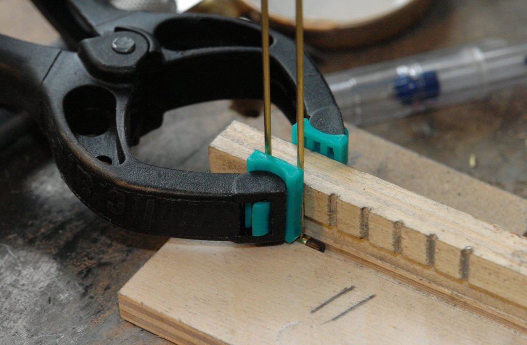
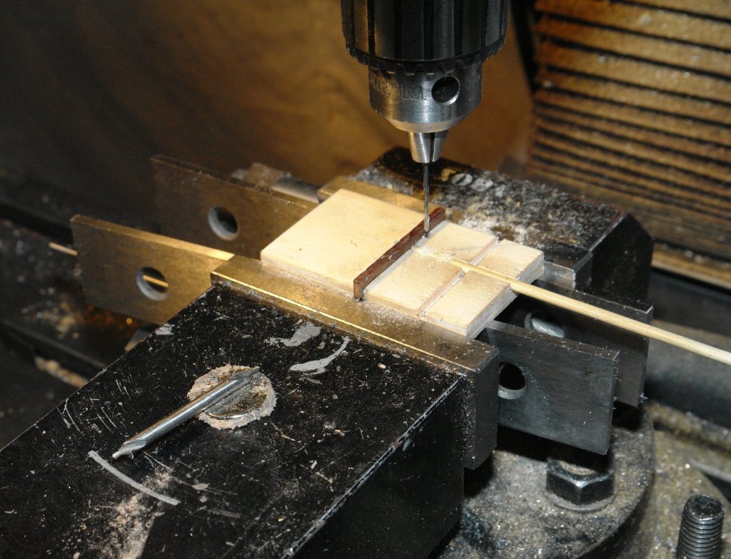
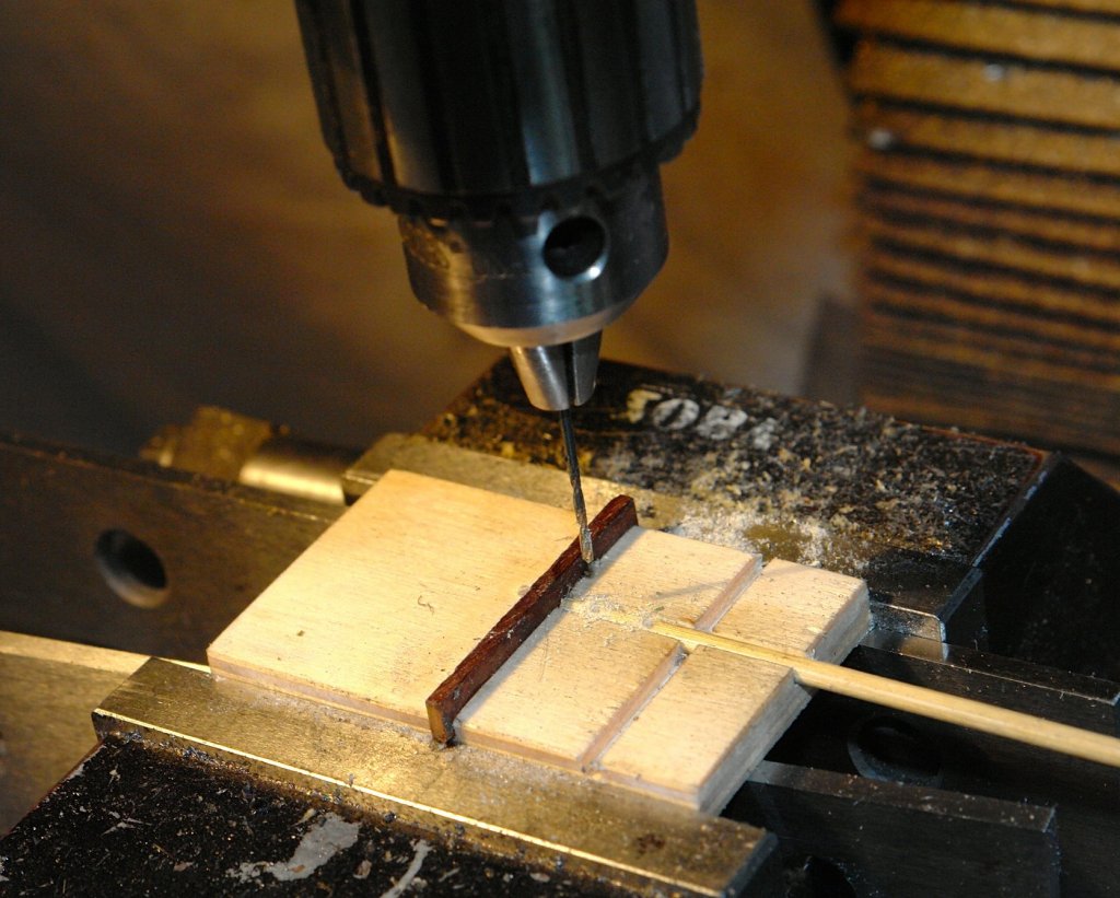
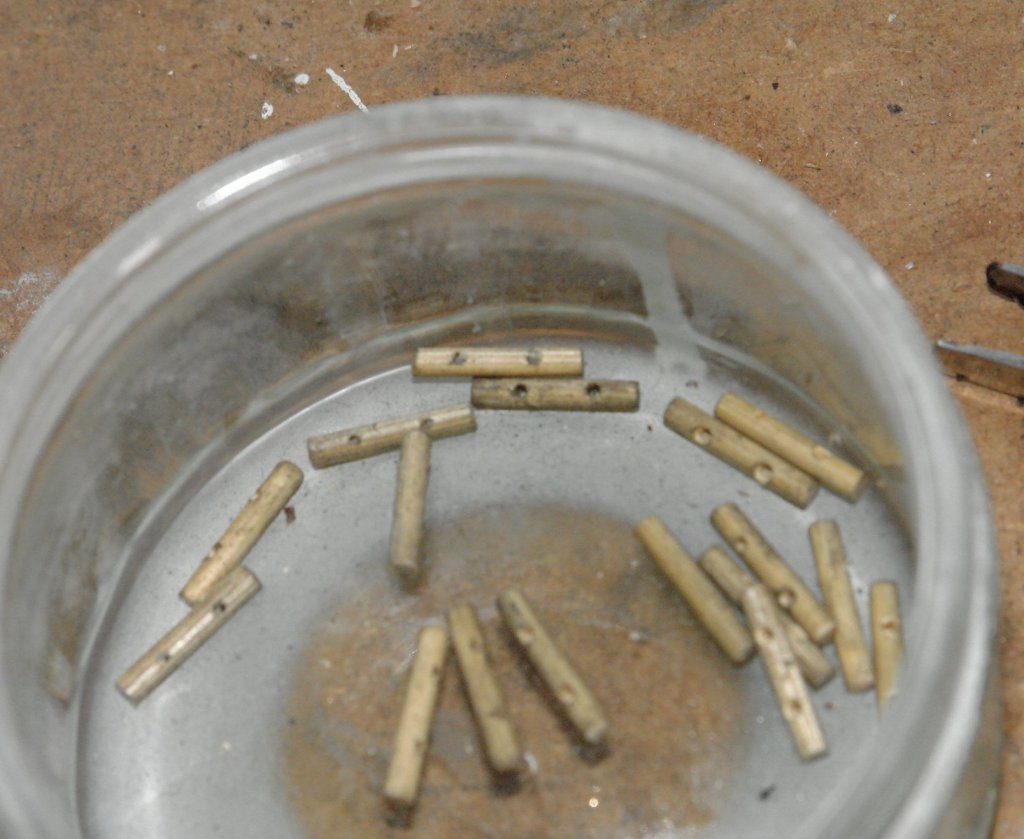
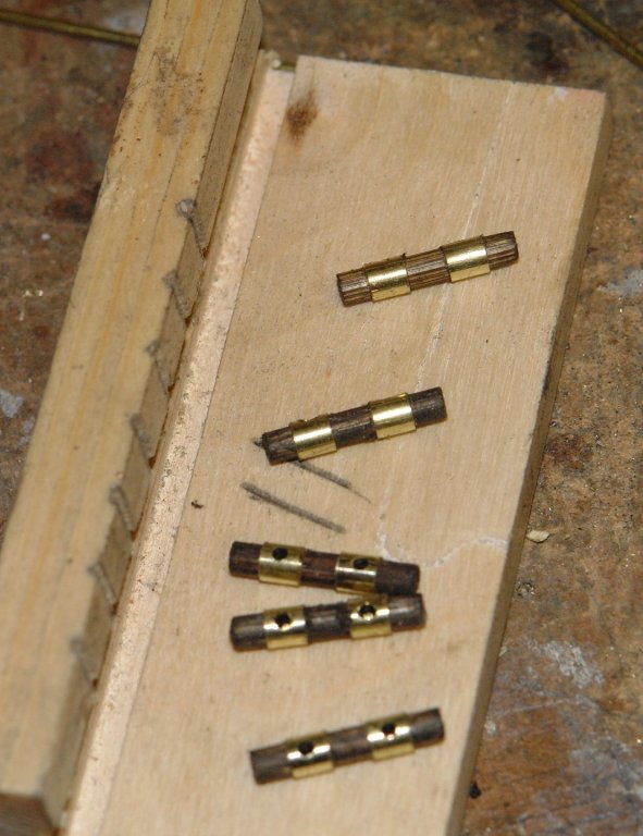
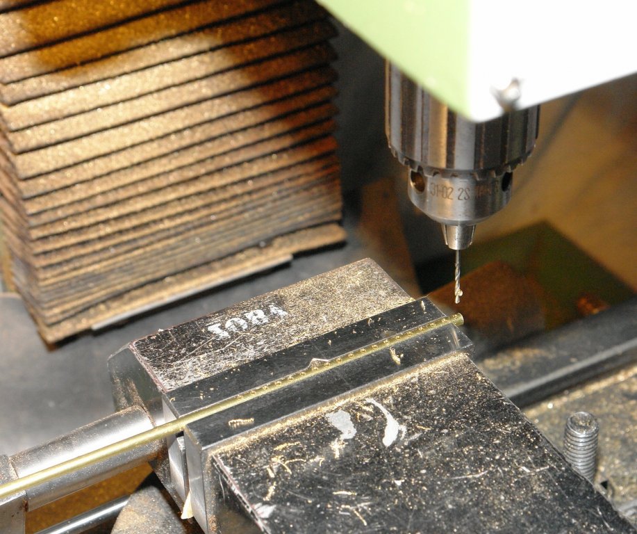
I have now made all the bits for the cleats. The last bits to be made were the wooden cross members. The cross members were made out of barbecue skewers (bamboo). I didn't have any the right size (0.1" diameter) and anyway the cross section was all sorts of shape. A job for a draw plate but as I don't have one I had to make my own. The holes were drilled using a centre drill. The first hole in the plate was drilled through until the conical section just penetrated the underside of a plate. Subsequent holes were then formed with each hole penetrating .005" deeper than the previous one. The cone of the drill thus generated increasing sizes if hole. I drilled one hole wrong - spot the deliberate mistake. The holes had very sharp edges and worked very well. All the skewers finished up round and between .098" and .10" diameter. The cross members needed .04" holes drilled through them .250" apart. I made a simple jig to accurately hold the skewers during drilling. I have a load of rare earth magnets which I use to hold drills, milling cutters, etc while I am using using them for a specific task. I find it stops me losing them - particularly if they are small. The magnet here is holding the centre drill as i repetitively change between it and the twist drill. I needed 18 cross members so I made 20. Somehow I immediately lost 2 so made another 2. I then coloured them with wood dye. Colron spirit based wood dye. I am down to the last dregs of the tin and Colron have discontinued this dye because of VOC's. The pity is that the water based replacement product is useless and does not work. Hopefully someone will know of a decent product???? I have started assembly.


-
UK Supplies of good blocks and rigging line
KeithAug replied to JRB9019's topic in Masting, rigging and sails
John Although I make my own you can buy nice wooden blocks and rigging line (and a lot of other fittings) here - Uk based supplier:- http://www.modellingtimbers.co.uk/1.html -
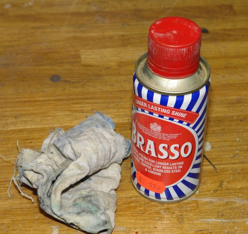
Bedford - re polishing If the part has machining marks I polish them out with progressively finer grades of wet and dry paper (used dry). I tend to start with 400 grit before moving to 600 grit and then 1200 grit. Where I can I tend to polish using a bench polisher. I have polishing compounds for hard and soft metals. The compound comes in coarse and fine grades. However I find that I don't get much use out of the hard metal compounds and to be frank as often as not I go straight to the "blue" fine grade compound for soft metals. That said I find I often want to do a small amount of polishing on an awkward component and here the convenience and simplicity of the following method tends to win out. In the words of a very old song:- Shine your buttons with Brasso It's only three ha'pence a tin, You can buy it or nick it from Woolworths. But I don't think they've got any in. The rest of the song isn't really printable on this forum but can be viewed on you tube.


-
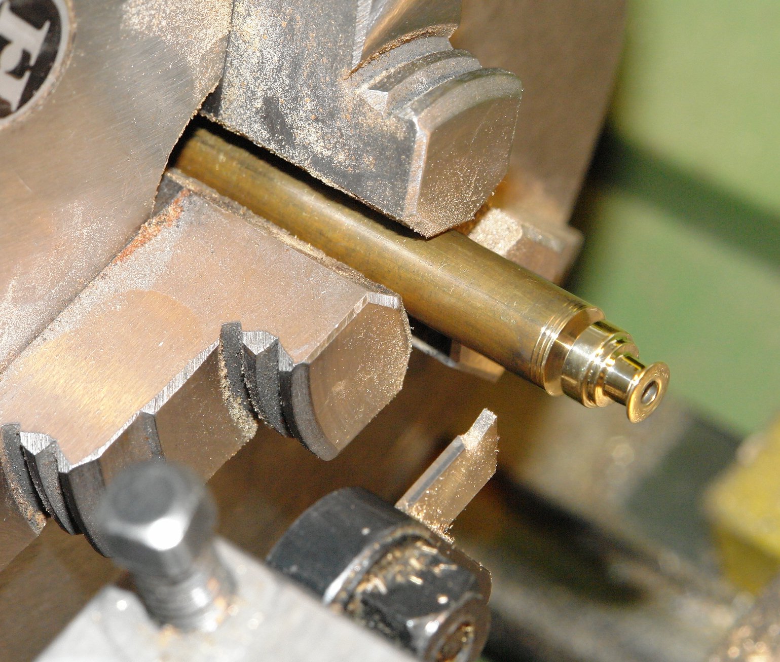
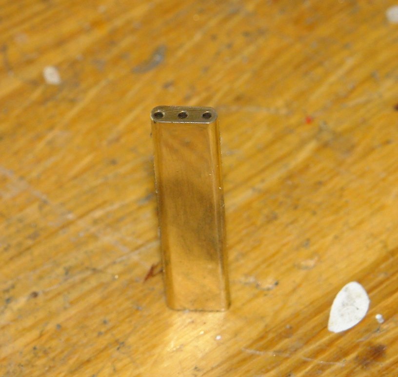
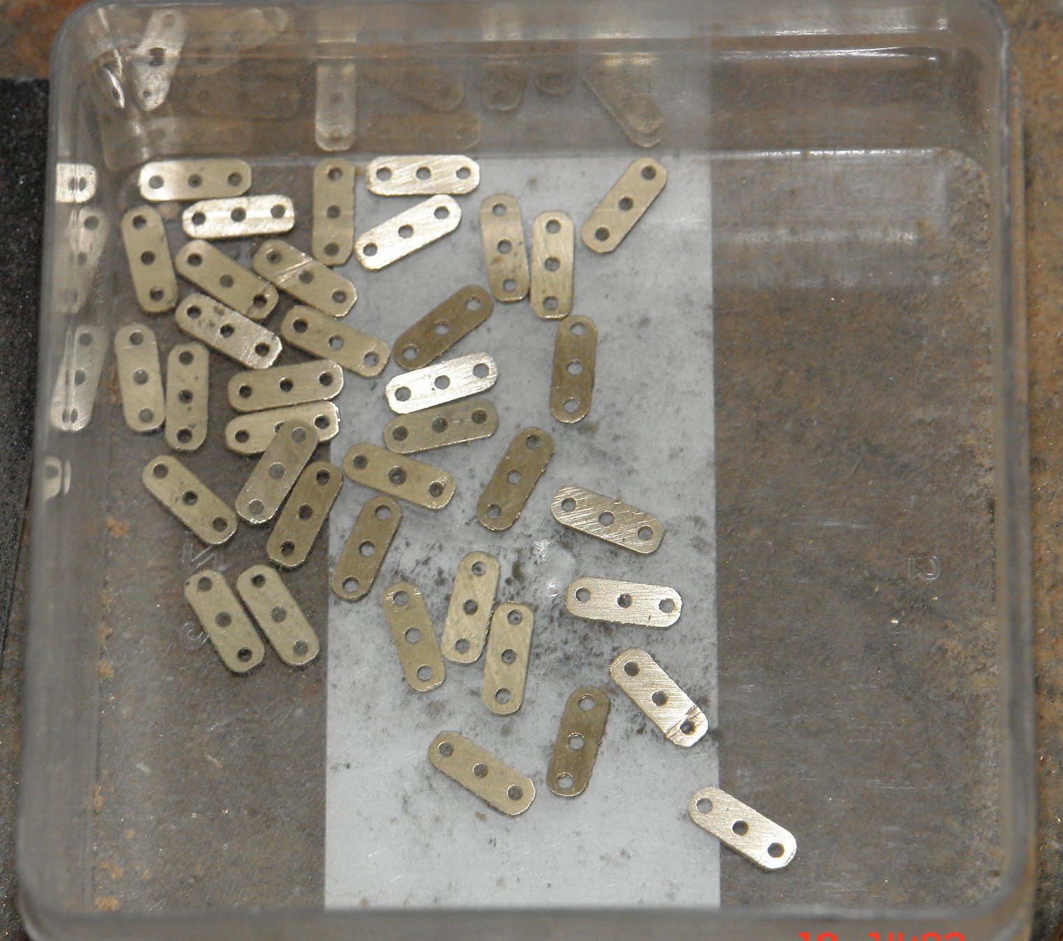
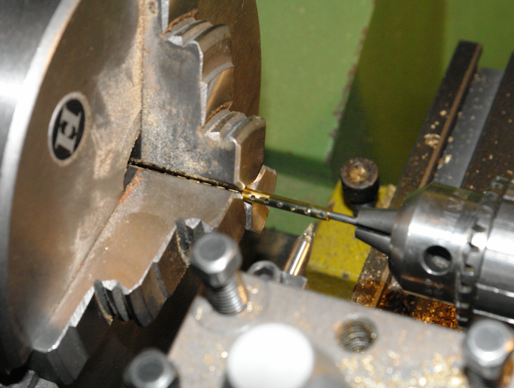
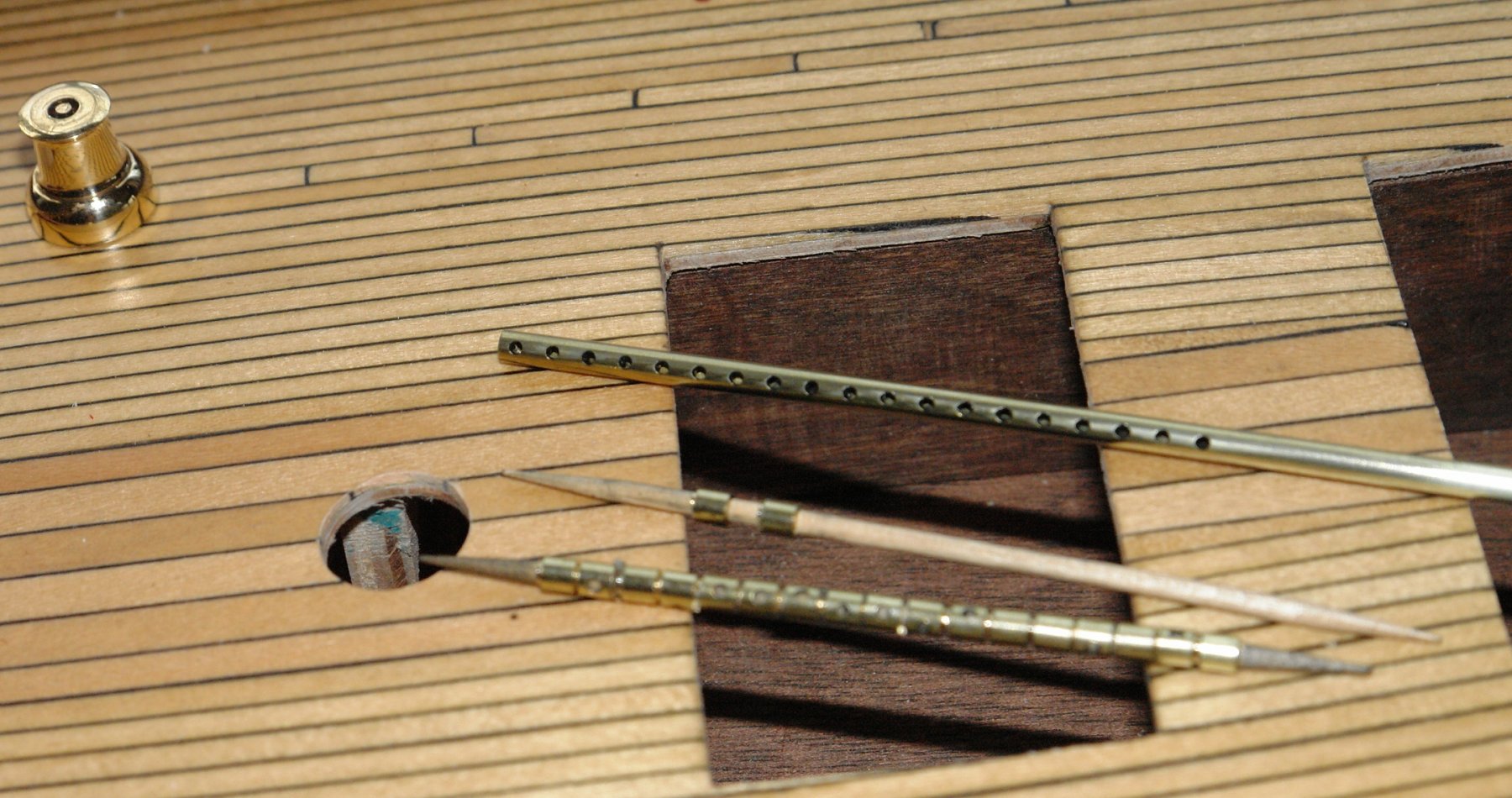
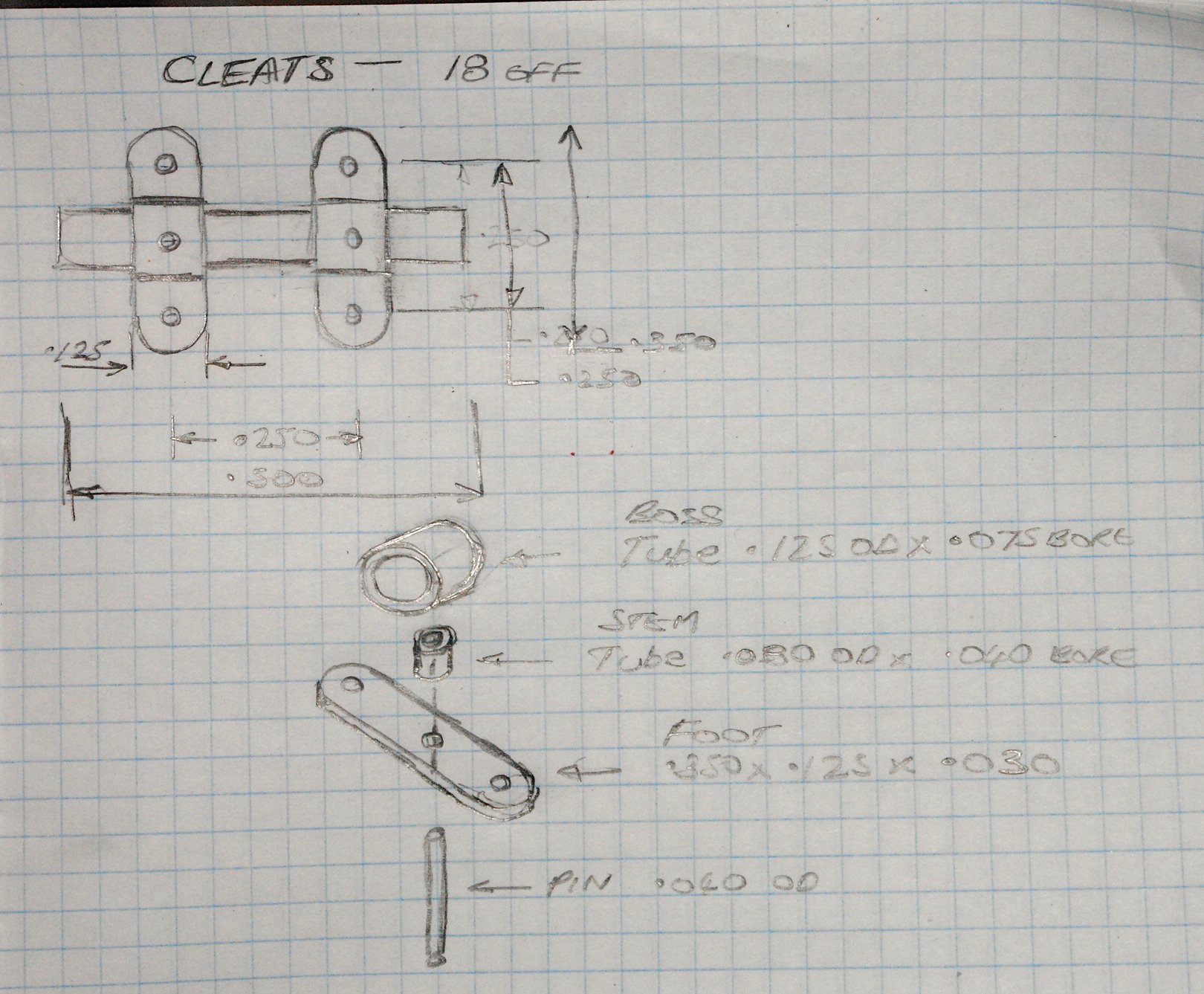
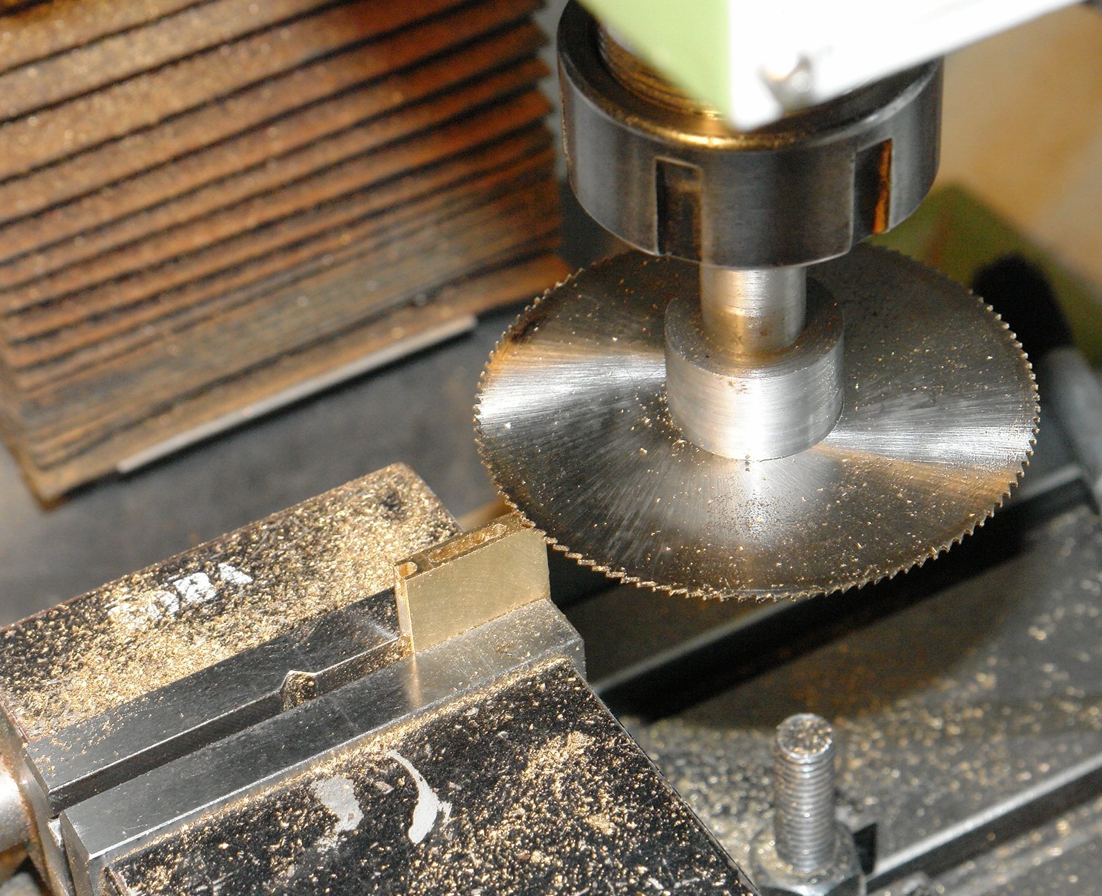
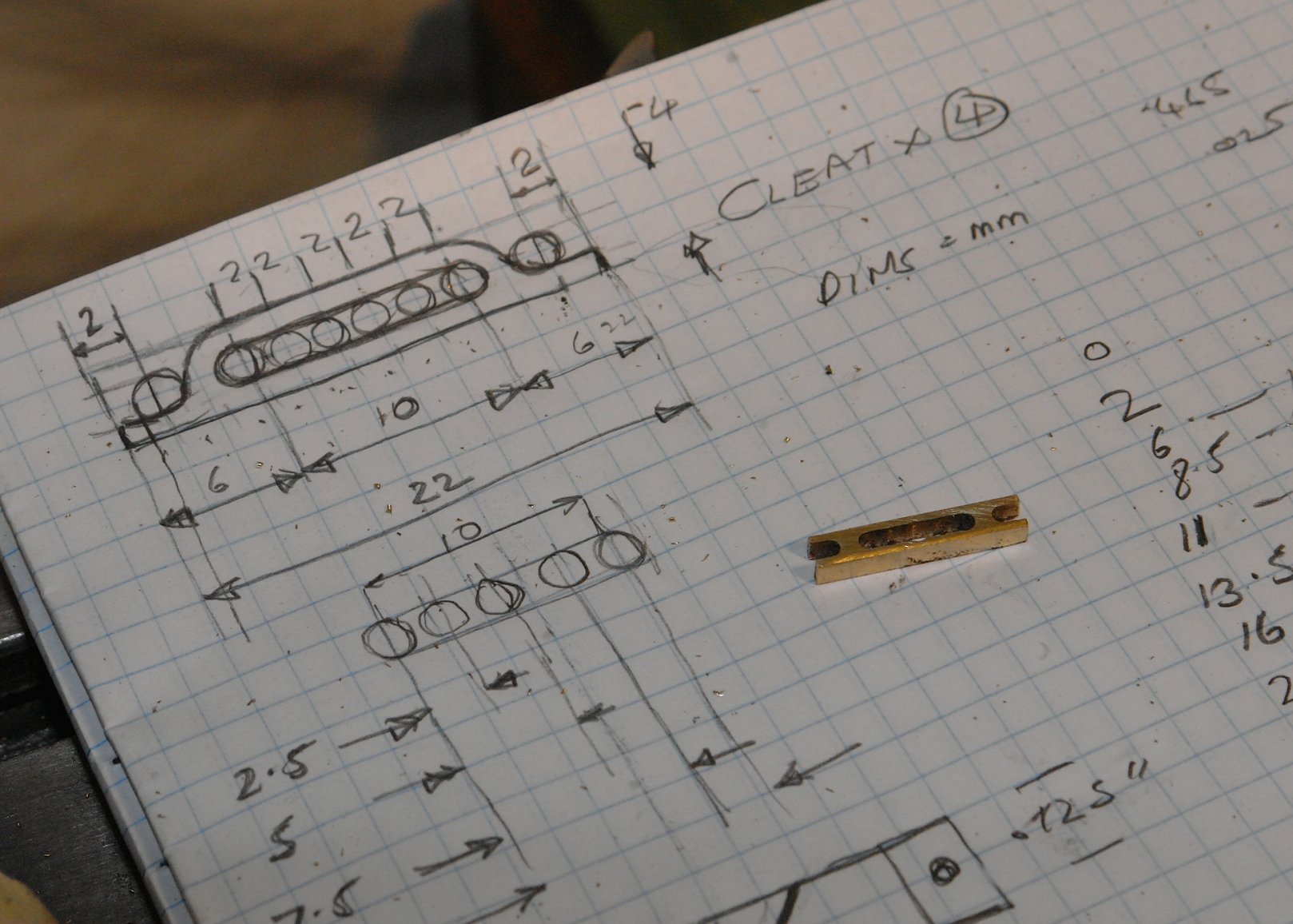
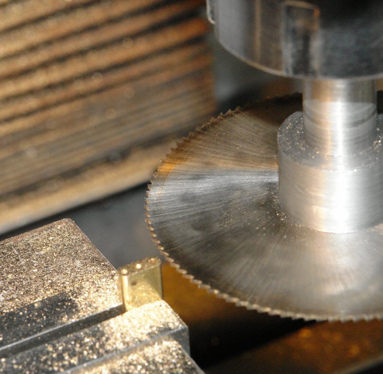
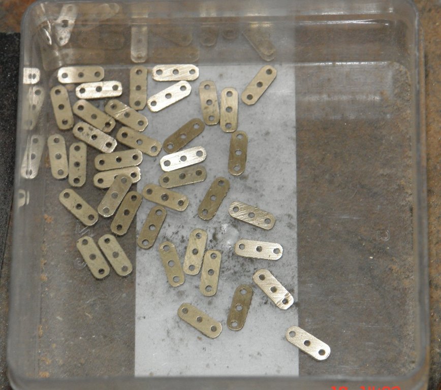
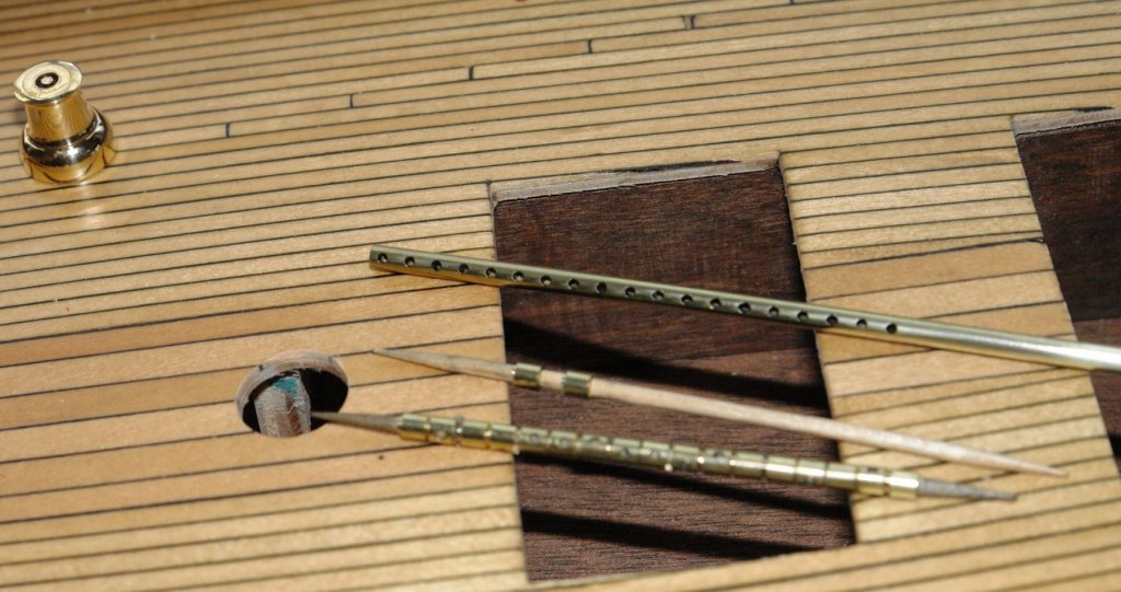
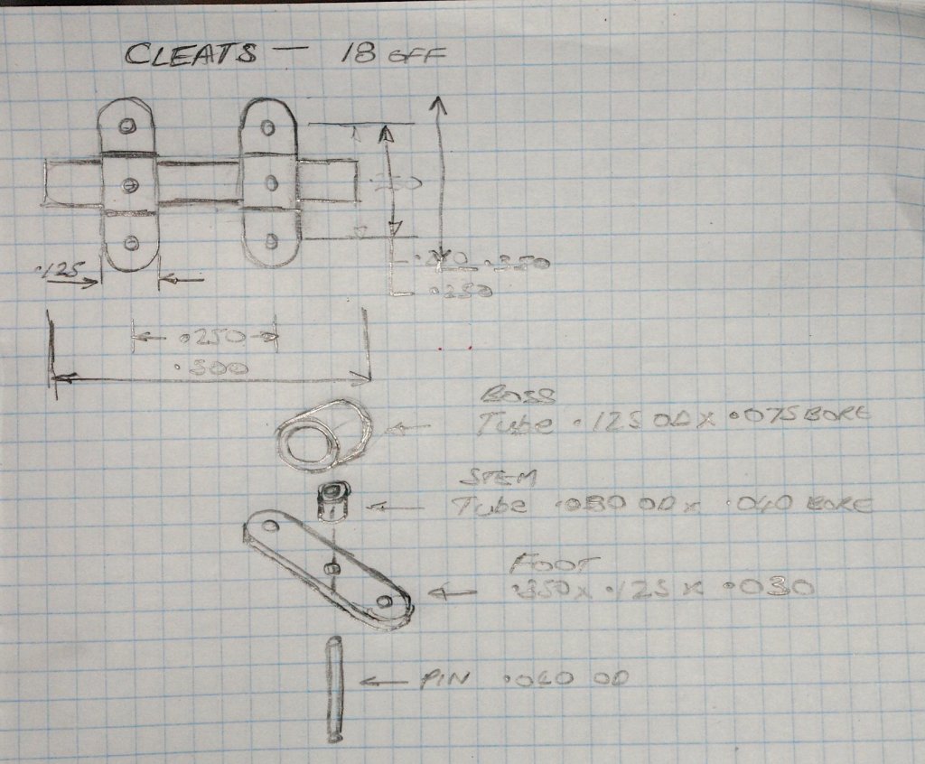
Michael, John, Richard, Thank you for the comments - much appreciated. Also thank you to all those who have visited my build. I hope you have all found a little to interest you. Bedford, I do love old ships and boat. The heritage fleet looks wonderful. Update:- I have made a start on the cleats 18 in all. I am fabricating them from a kit of parts - each cleat will be made of 9 components - so 18 x 9 = 162 bits in total. The basic design is shown in the sketch.It is important to get all the parts as similar as possible - I find discrepancies show up particularly if you know about them! The foot was made first. I decided the best way to achieve consistency was to shape a brass bar to the plan view of the foot and then to drill the 3 holes. The bar was cut to size and finally shaped with a hand file. The individual feet were then parted off from this with the slitting saw mounted in the mill. The edges of the feet (photo above) still have to have burs removed before polishing. I miscounted and made 38 rather than the 36 required. The top boss is made from .125" OD tube. The tube was accurately drilled with a series of holes along its length. These holes will take the assembly pins. I needed to accurately part off the boss's from the tube. I was concerned that the tube would not stand up to the parting off operation without support. I improvised a steady by supporting the tube from the bore using the back end of a drill held in the tailstock chuck.The bonus advantage of the steady was that the very small boss's were retained on the drill shank. I am using cocktail sticks to make sure the boss's don't go walkabout.


-
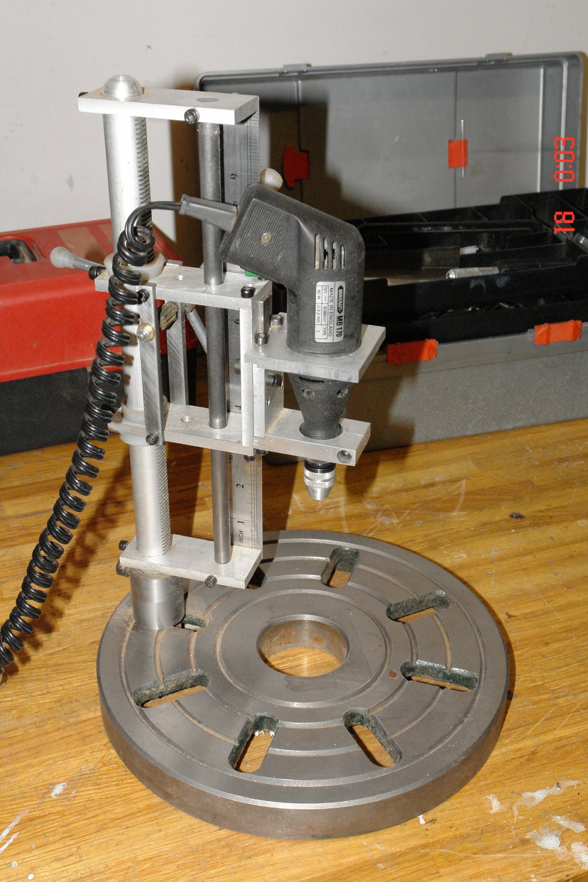
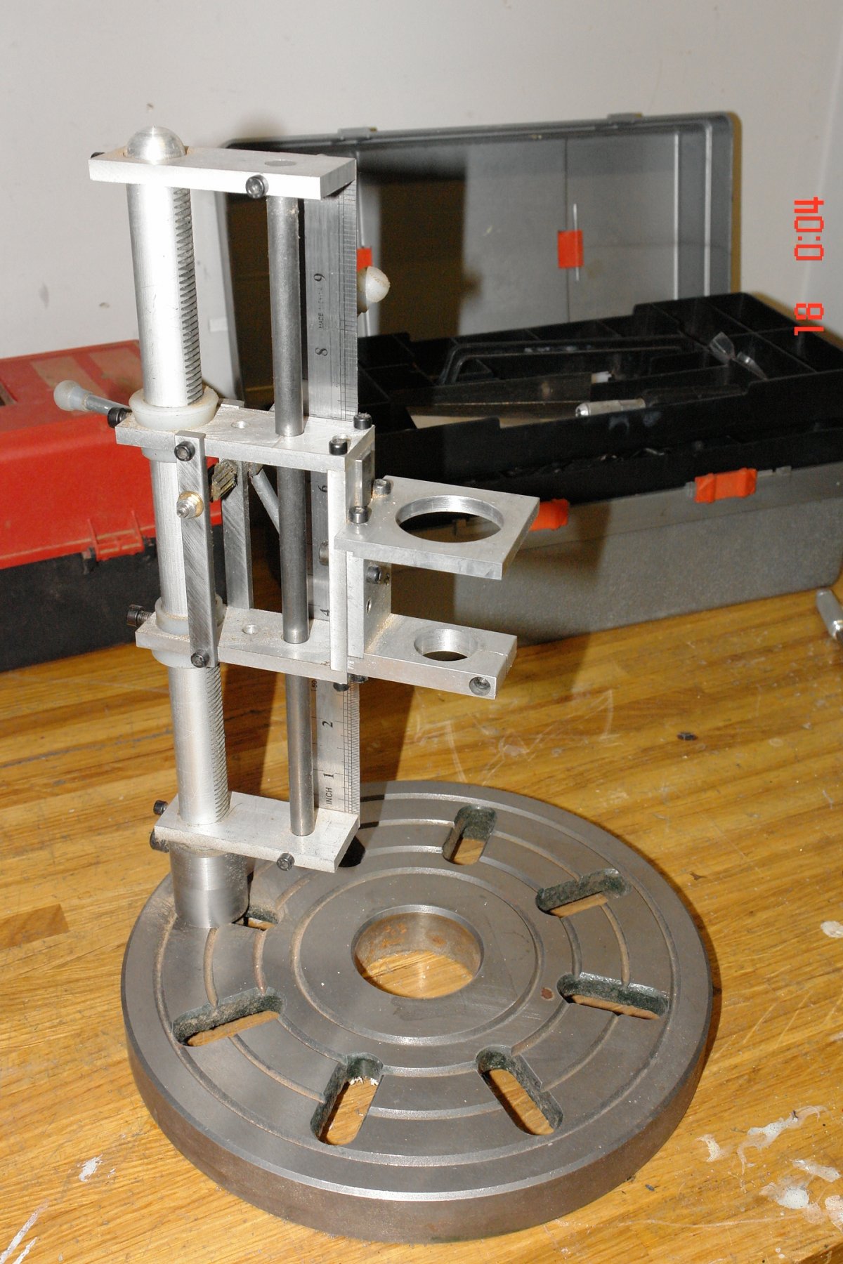
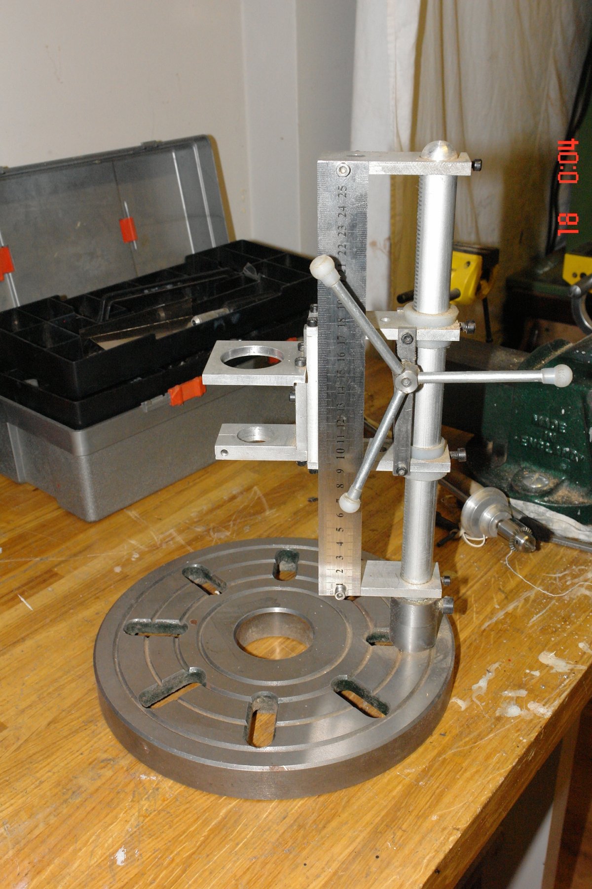
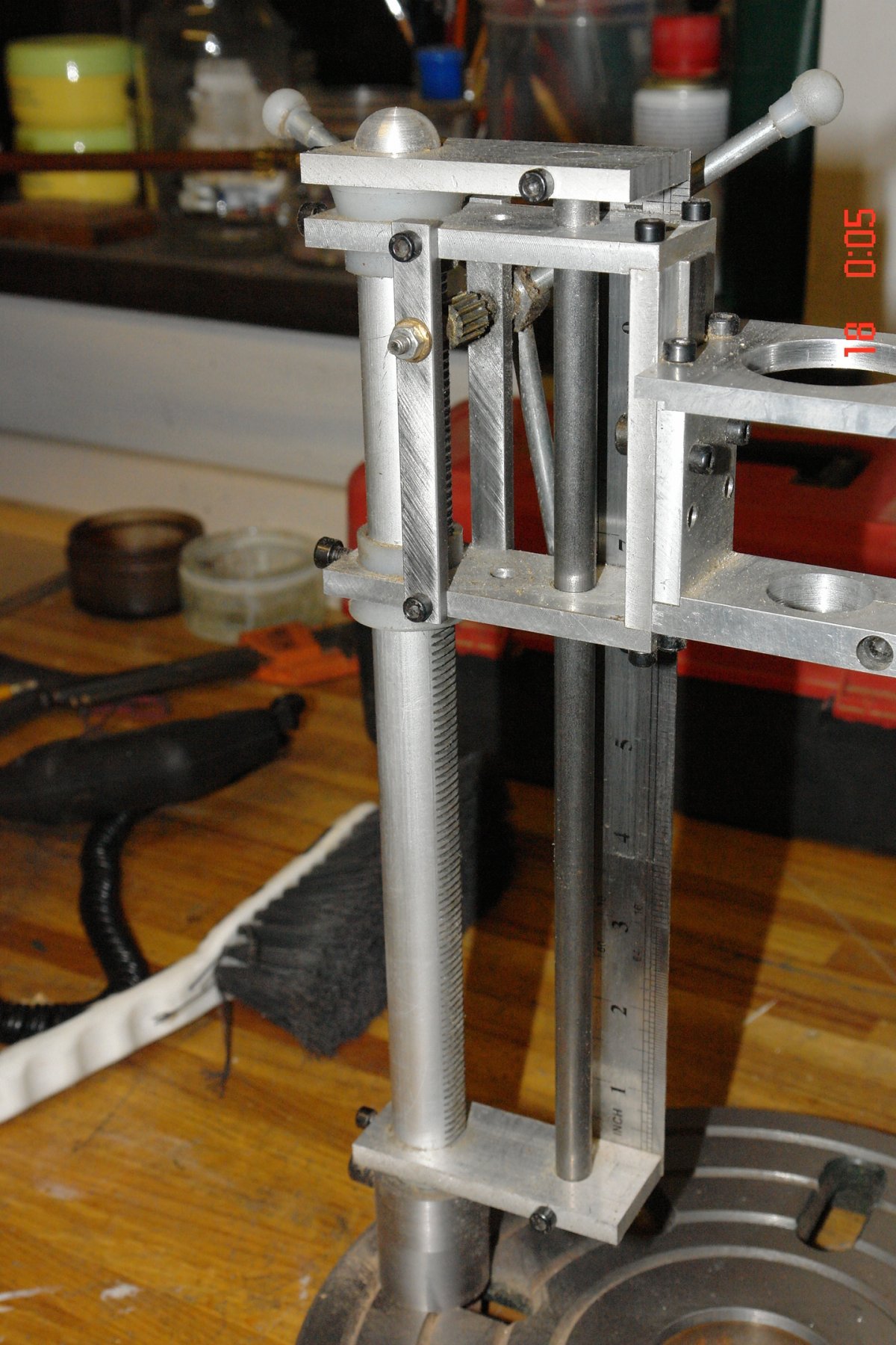
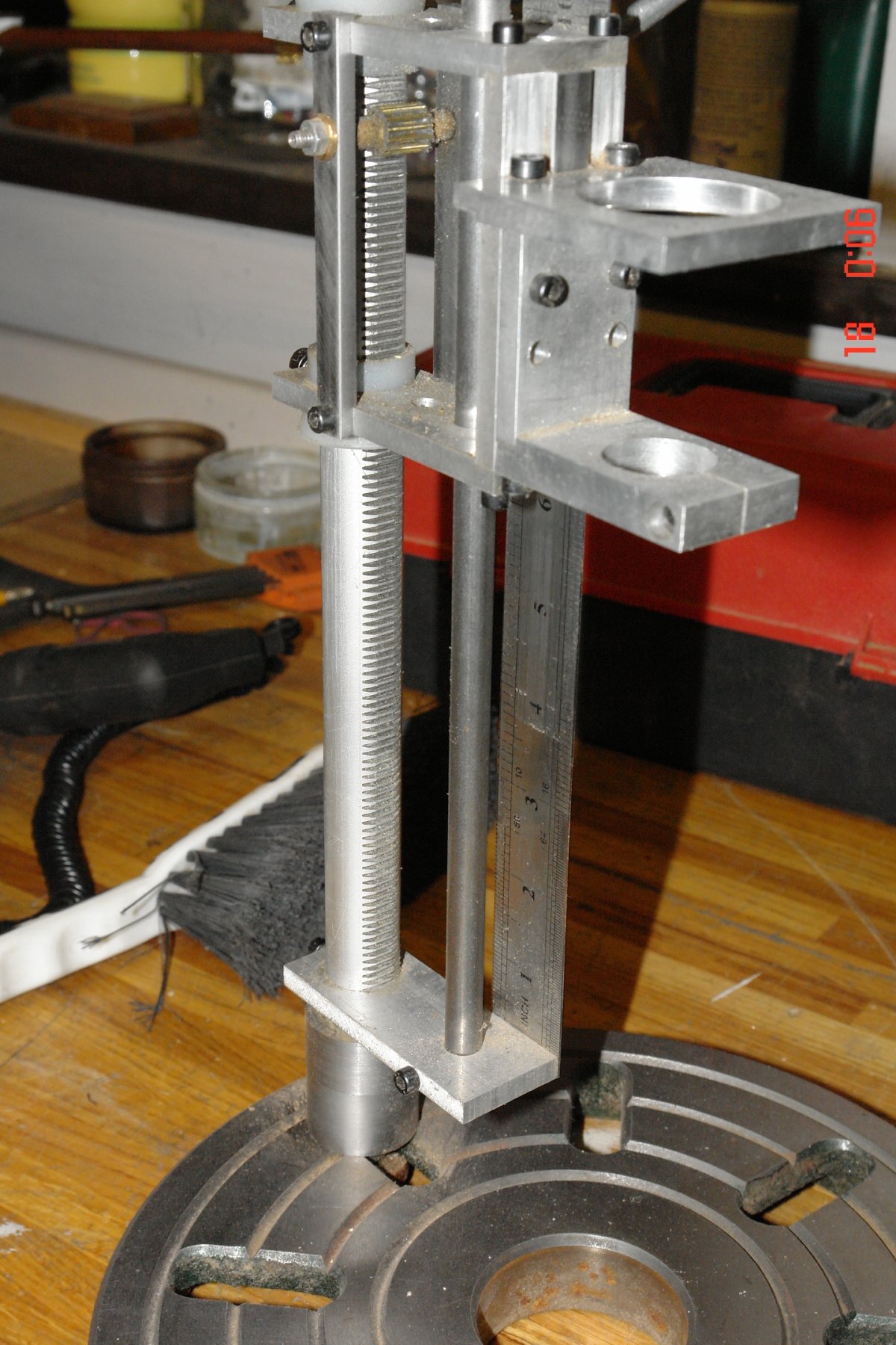
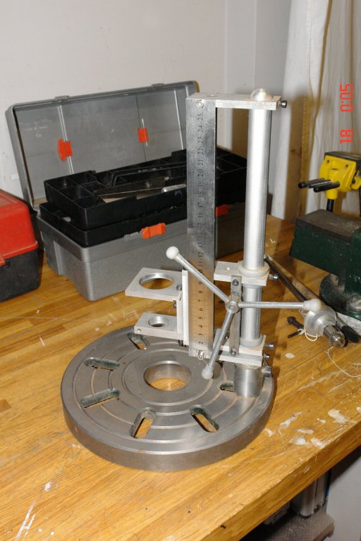
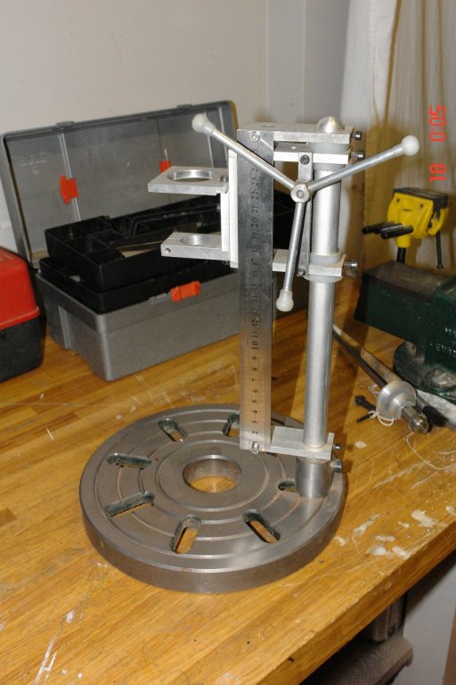
Hello Michael I thought you might like more detail about my approach. Like you I didn't like the commercially available units. The press was designed around my micro drill (now very old - at least 25 years). The base is the face plate off the lathe - rarely used with the lathe. The main column is the central rising shaft from a broken camera tripod ( the legs are still waiting to be made into a 3rd hand ). If you look you will see the pinion gear which engages the rack. It was originally part of the hand lever which raised and lowered the rack. The horizontal plates at the top and bottom of the rack are rigidly attached to the rack and they carry, and are rigidly attached to, the vertical bar which sits to the right of the rack. This forms a very rigid structure on to which the sliding frame which carries the drill sits. What is a bit odd about this arrangement is that the 3 armed handle for raising and lowering the drill actually goes up and down with the drill. The photos are probably clearer than my explanation. Interesting how the same problem can spin off many solutions. Not quite as elegant as yours but it works and appeals to my need for recycling.


- 56 replies
-
- 14
-
-
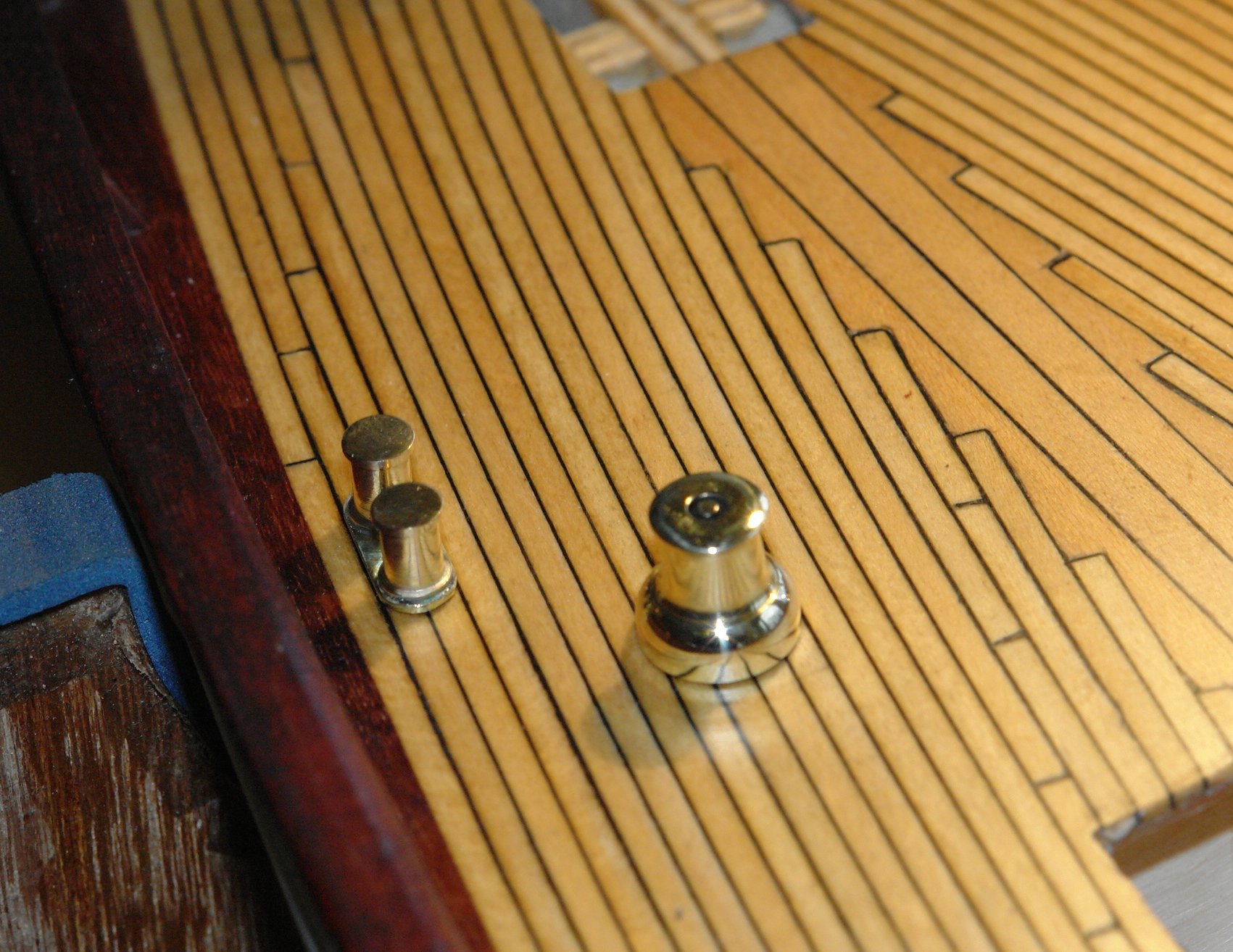
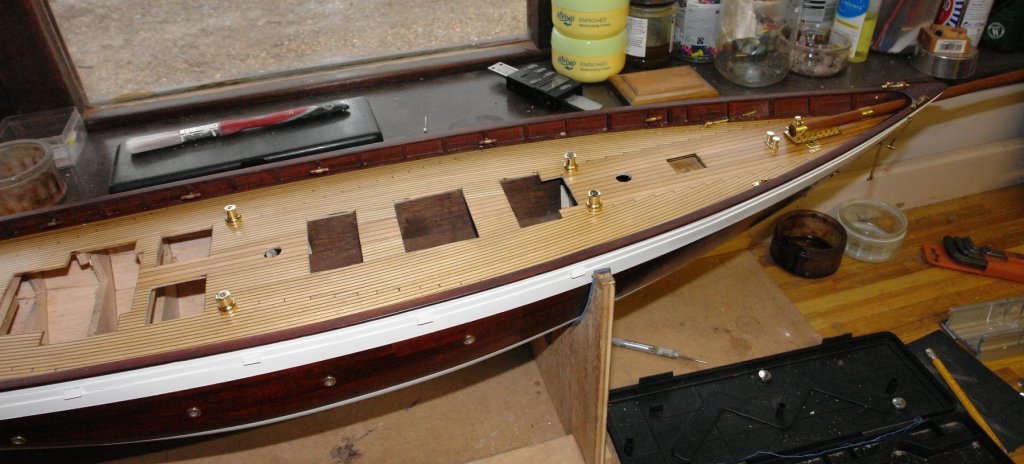
Today I did a bit of turning - bollards and the 6 larger winches. The plans only show the 6 deck winches whereas photos / videos clearly show some smaller secondary winches which I will have to make and position. The critical task was marking out the position and making sure that I drilled the mounting holes in the correct position. Check twice cut once was the watchword of the day. Nothing much further to add other than a few photos.


- 882 replies
-
- 12
-
-
Thank you Druxey. Greg - thank you, good point. Only a little progress today:- I made the mounting feet for the crutch and attached it to the deck. The feet are quite small - a smidgen over 1/8 inch cube. I also made the deck mounting for the "red duster". Made of two parts soldered together and machined. And then polished

- 882 replies
-
- 12
-
-
ancre La Salamandre by tadheus - 1:24
KeithAug replied to tadheus's topic in - Build logs for subjects built 1751 - 1800
Pawel, Was the original this well built? Somehow I doubt it. -
Hollo Bedford. Re crutch: I have rationalised the non conformance away by convincing myself that the original crunch was damaged and had to be replaced by a strapped for cash owner. John. Not so much beyond the curve, more likely "round the bend" - which over here is a euphemism for going mad! Mark. Thank you.
-
Thank you Mark. I'm surprised you have been so forgiving at my departure from absolute authensticity. Particularly as you ripped up the deck just to improve the randomness. Now that's what I call perfectionisim.
-
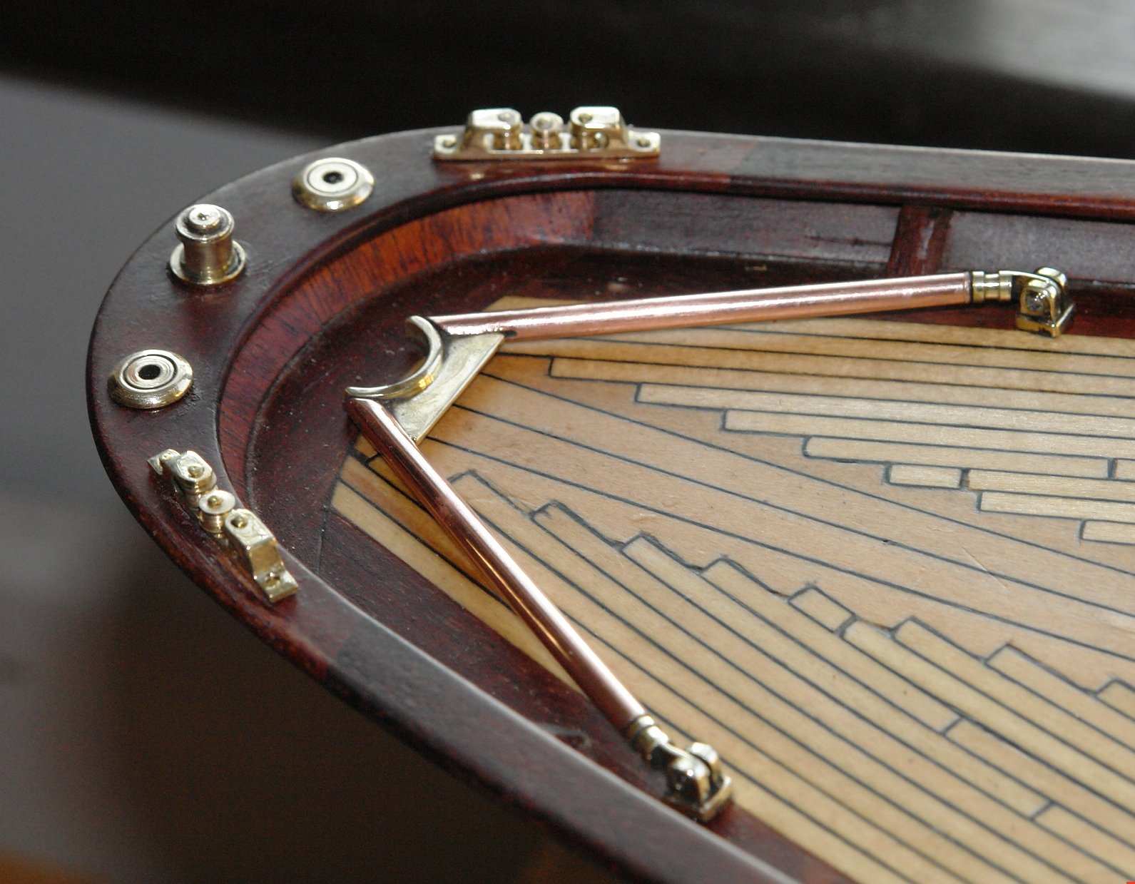
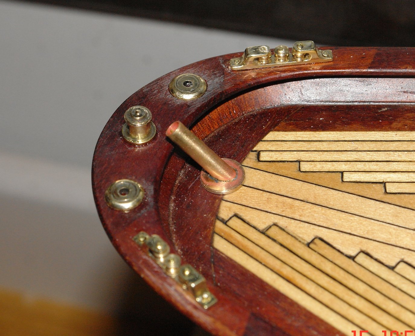
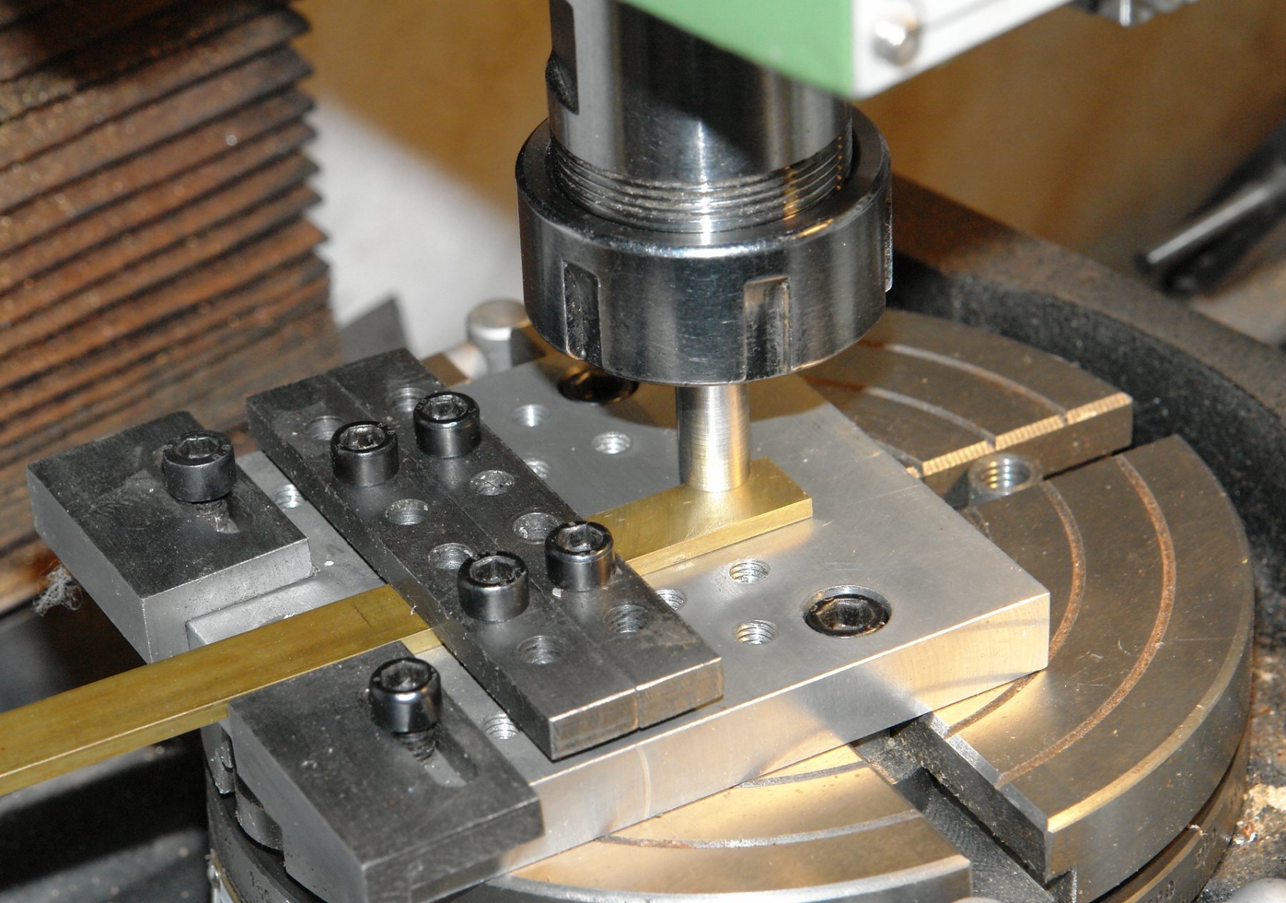
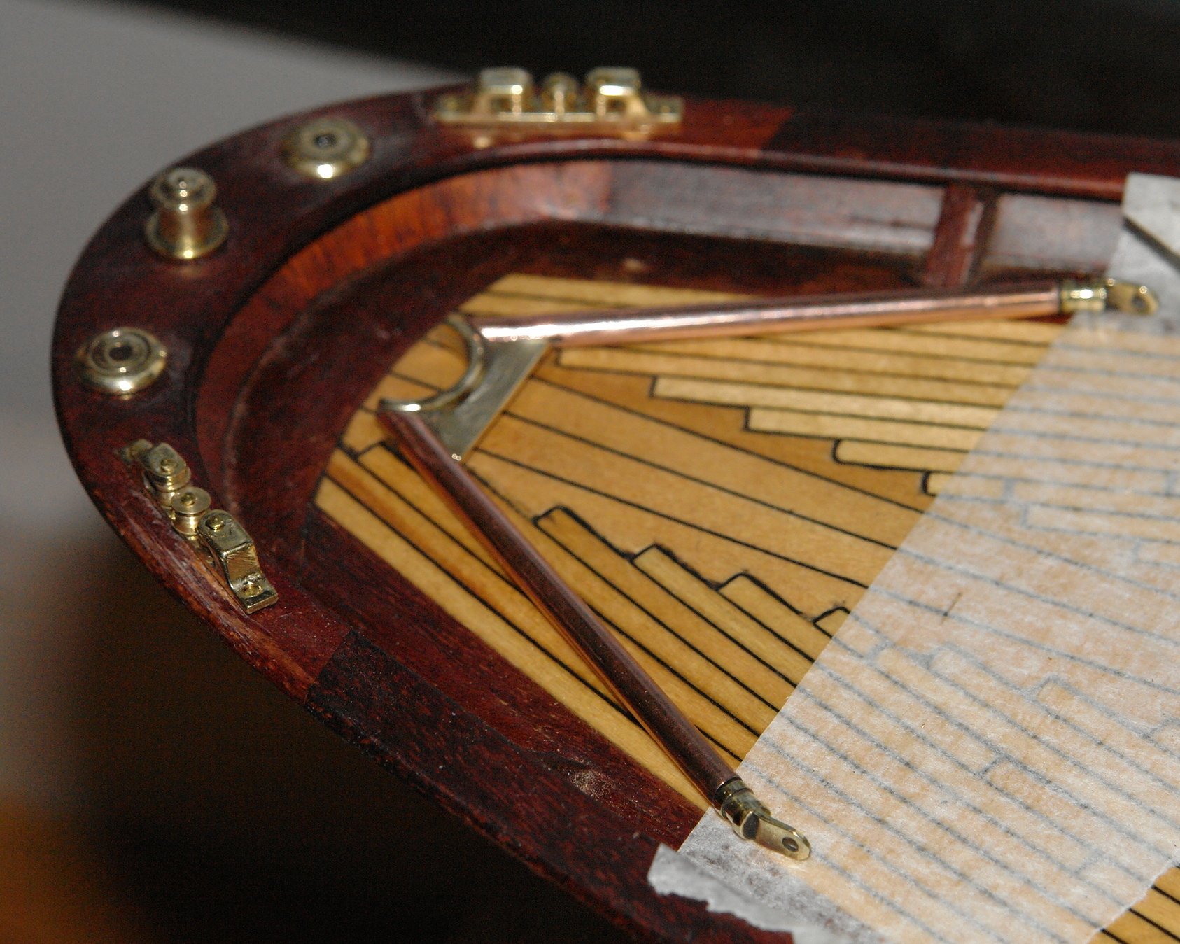
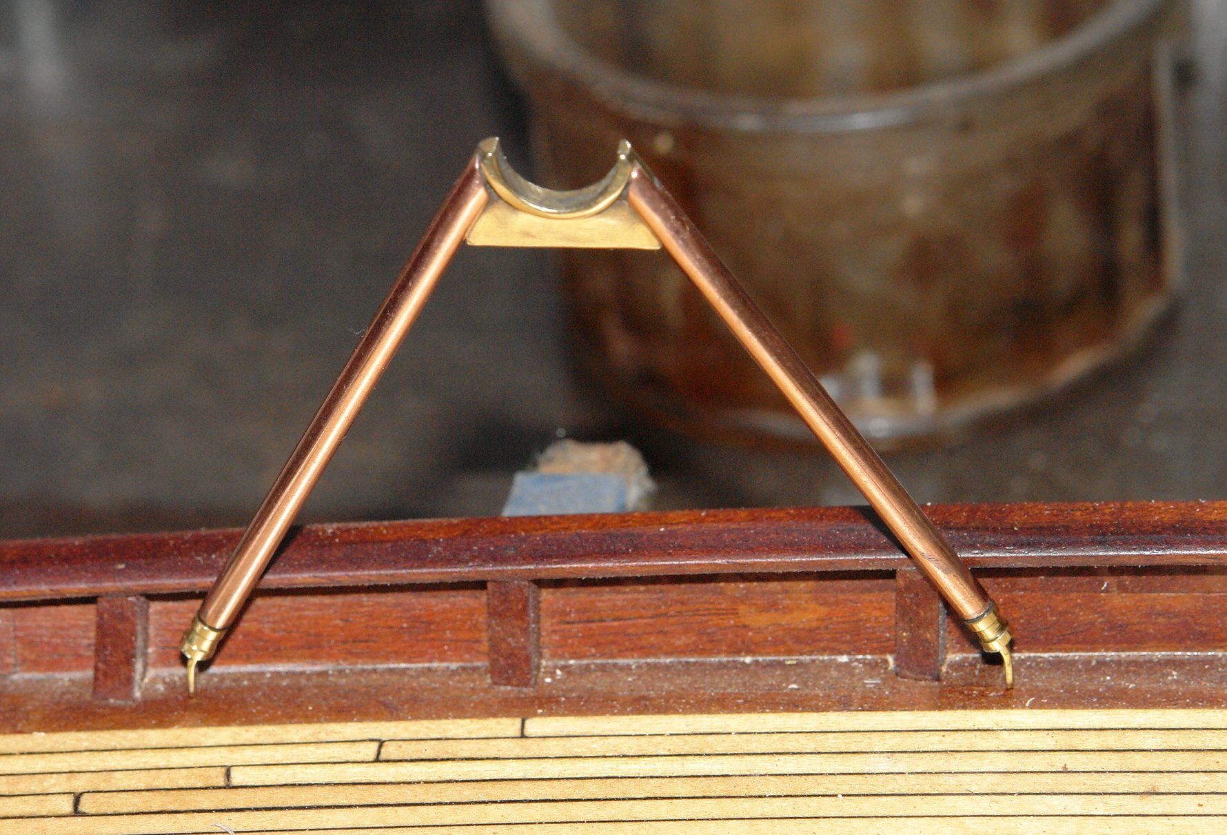
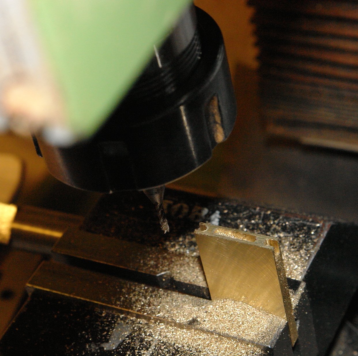
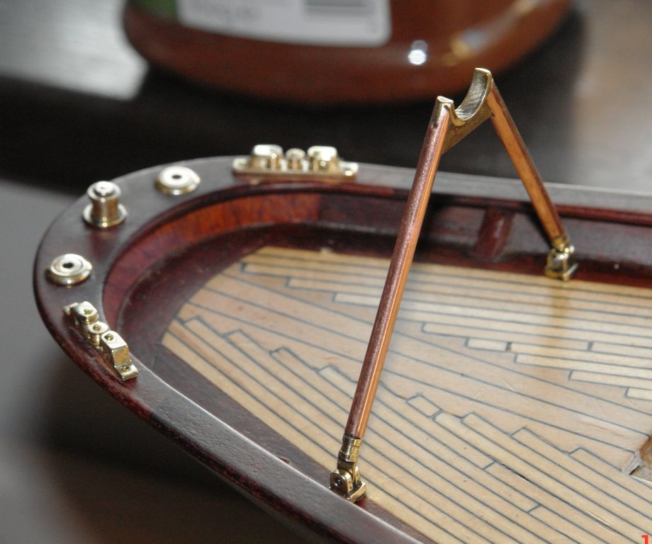
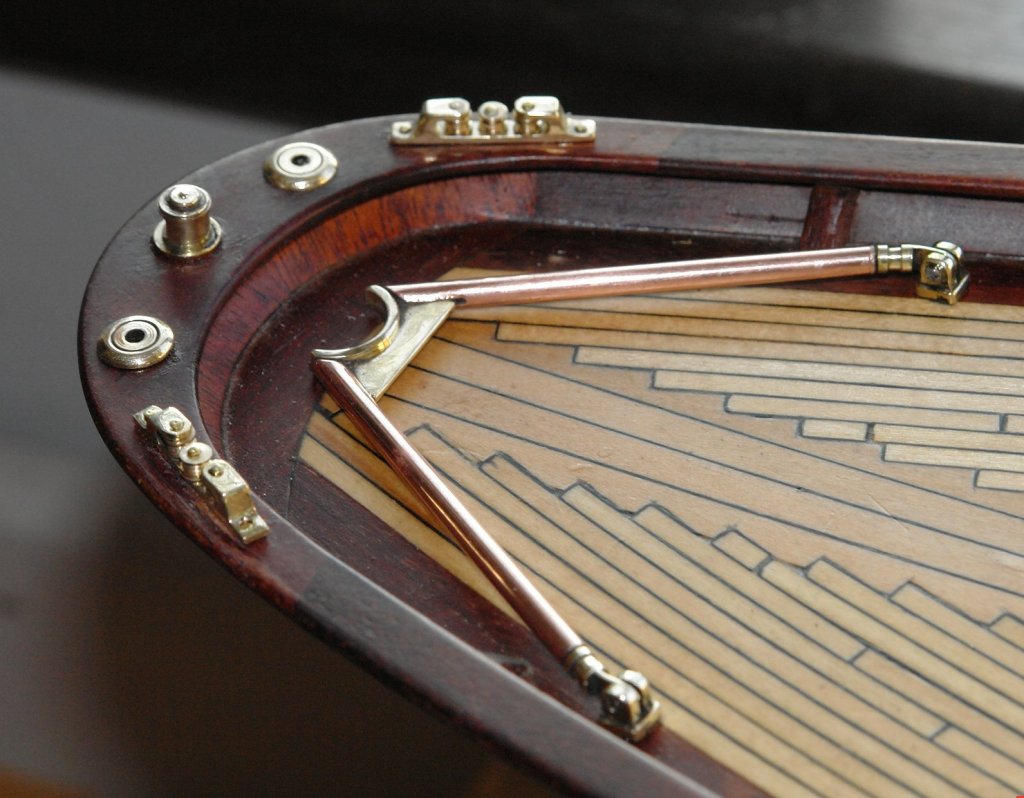
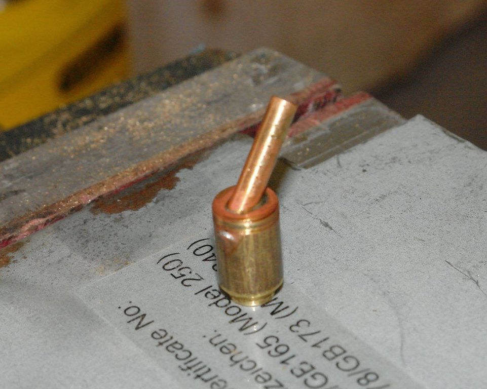
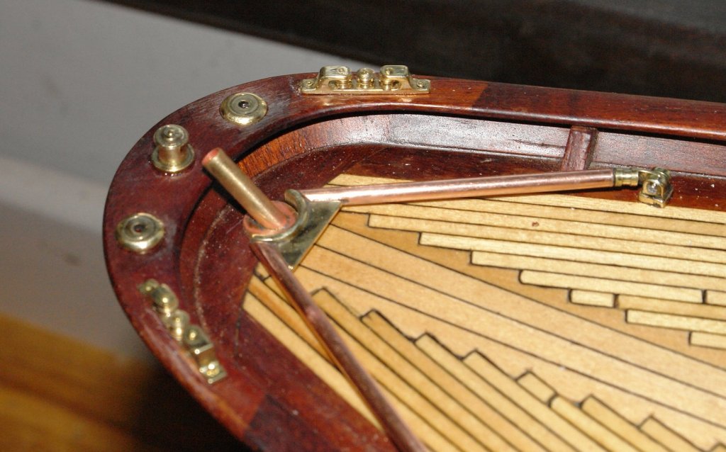
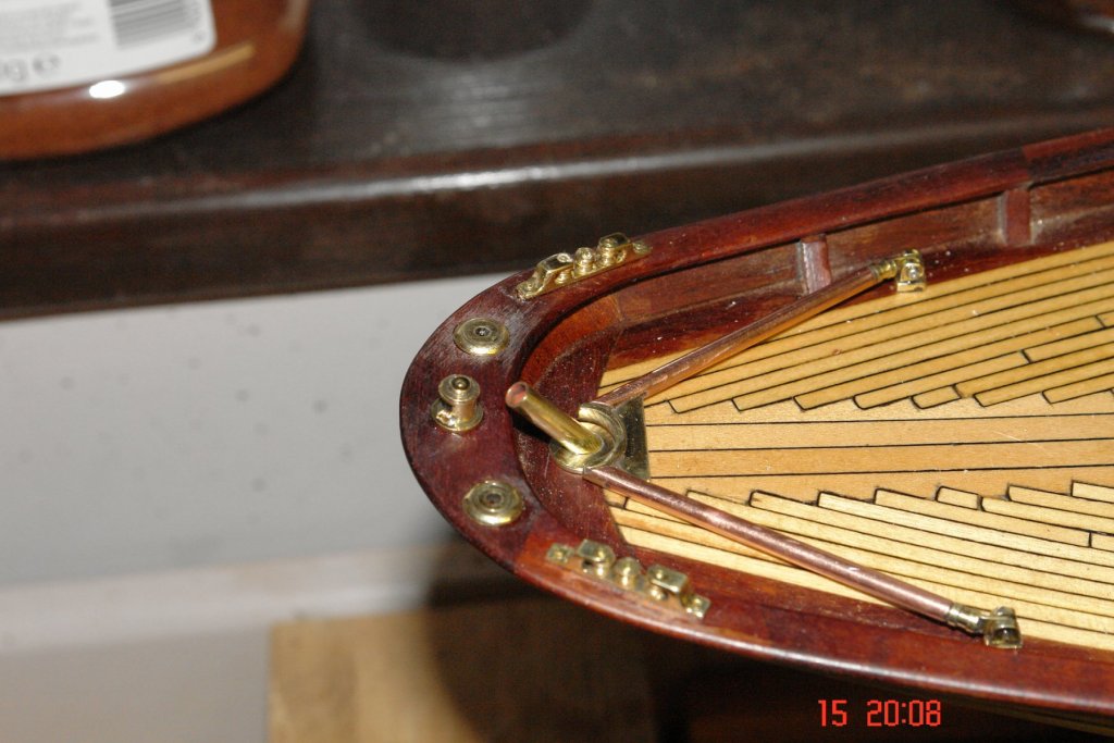
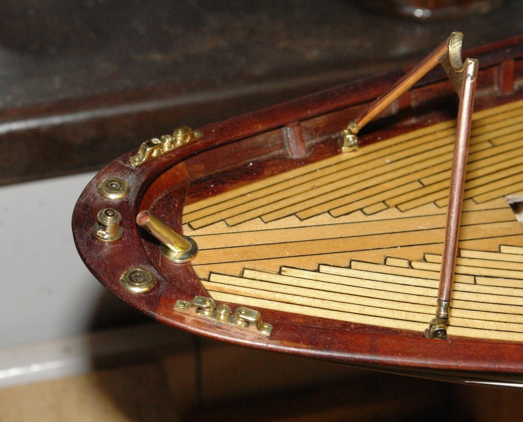
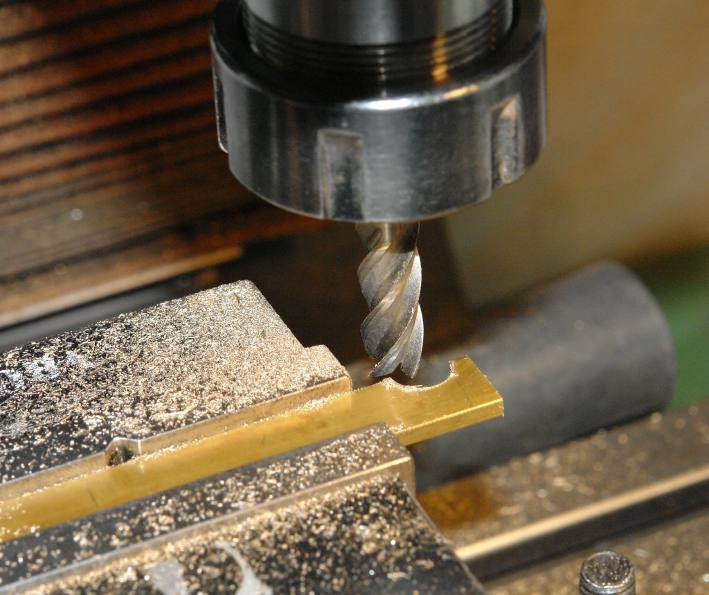
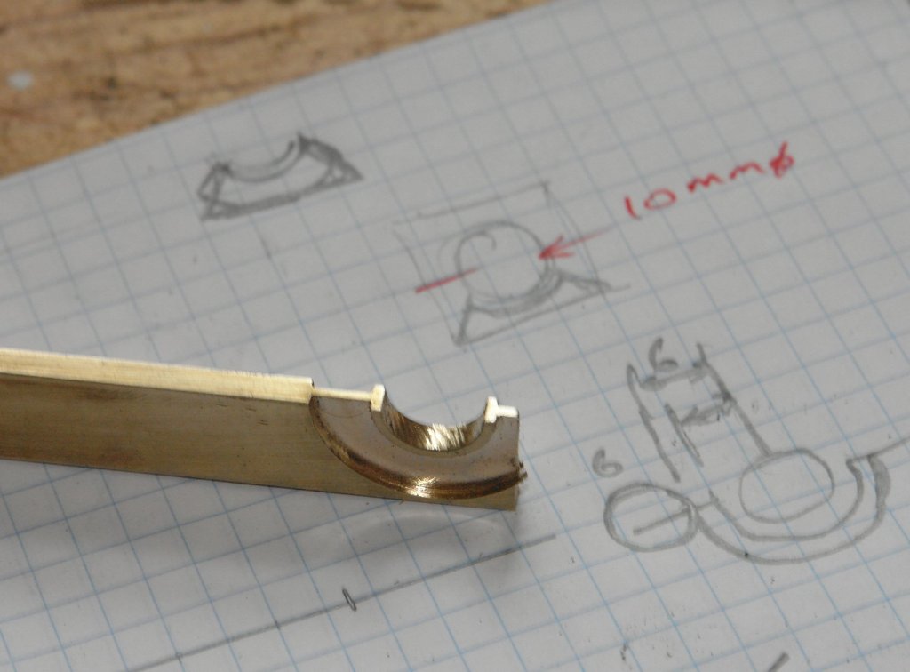
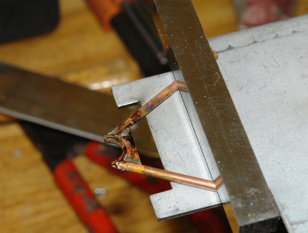
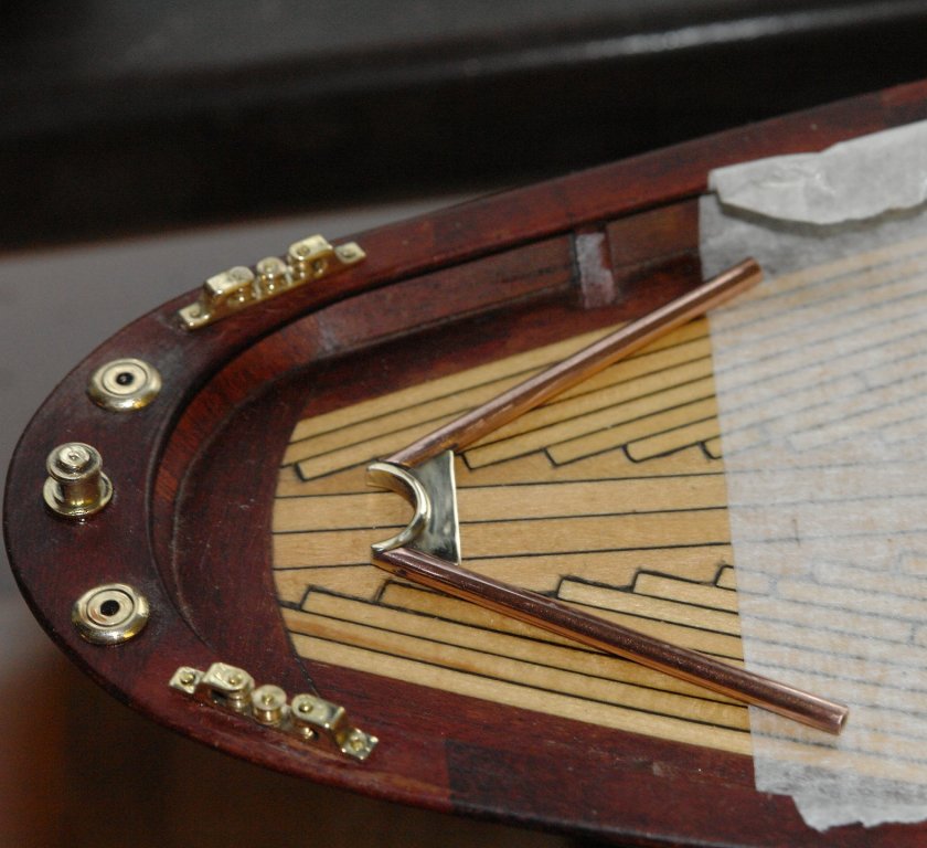
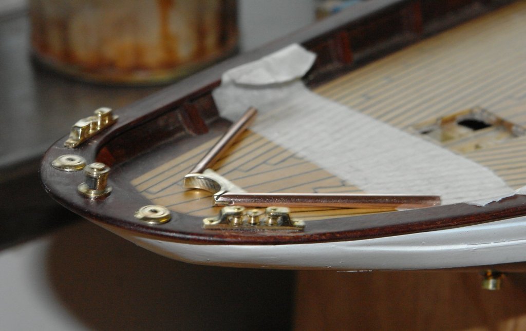
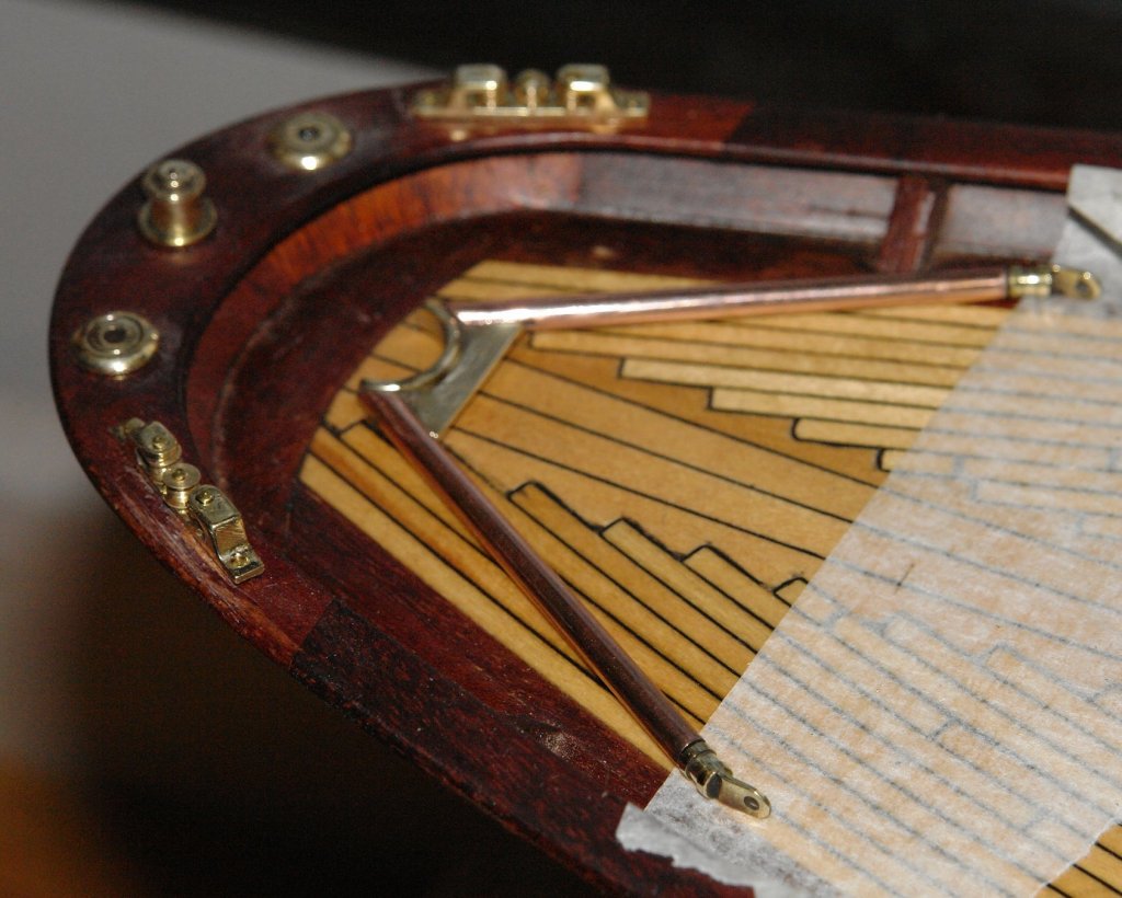
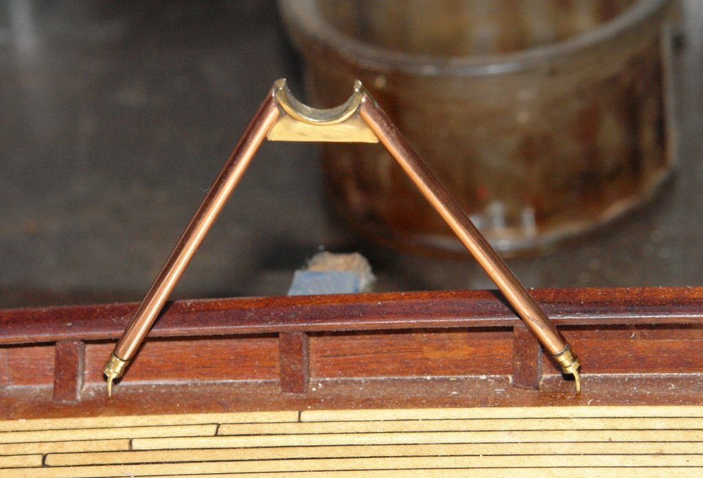
I had a go at the main boom crutch. On Altair this is a "A" frame - a rather crude affair which has the appearance of being made out of galvanised scaffolding poles. It is quite out of keeping with the other brass deck fittings. I couldn't bring myself to make a crutch that matched the original so I made something a little more in keeping. If I get a flood of derision from the purists among us I'll consider painting it grey. The top bracket has a circular cut out in which the boom rests. I machined this out of bar on the mill. The web was formed by end milling using a rotary table. The bracket was separated from the bar and then the legs were soldered on. Cleaning up and polishing followed. As a bit of a distraction I made and mounted the stern light. I then made and attached the feet. The crutch lays flat on the deck and pivots up to the vertical when in use. But of course not in the position shown in the photo. Not sure I want to paint this!

- 882 replies
-
- 12
-
-
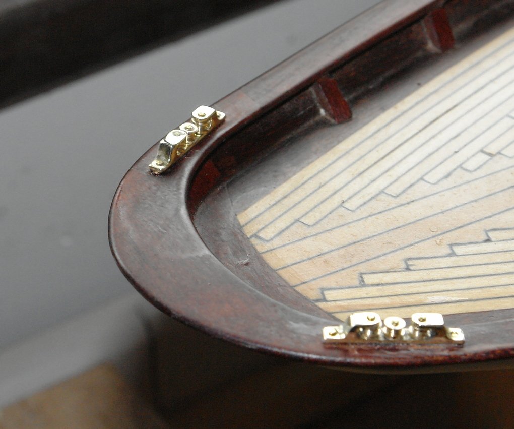
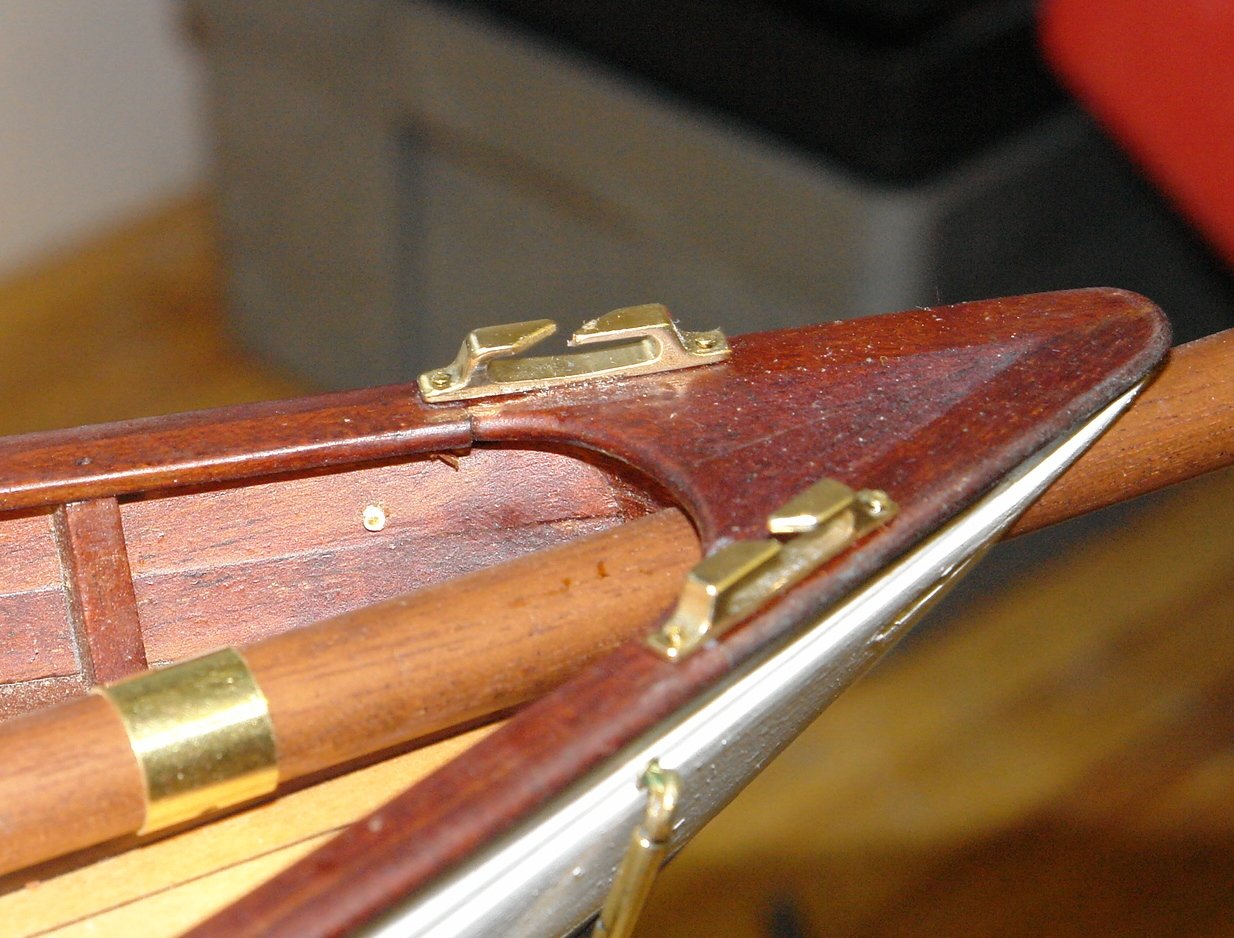
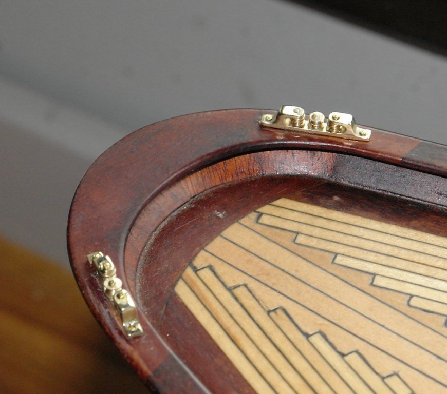
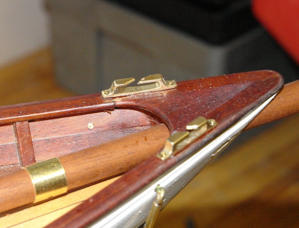
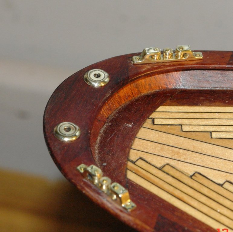
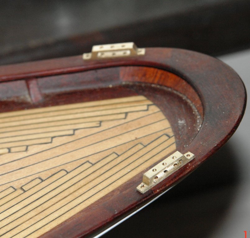
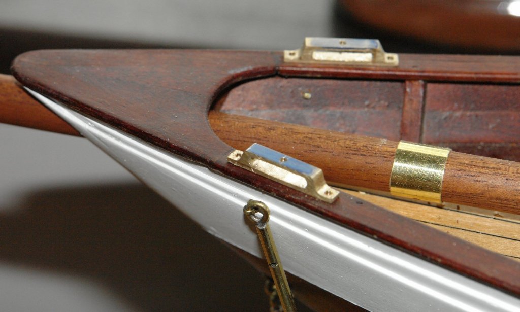
Richard, Kees, John, Greg. Thank you for your supportive comments. Also thank you to all the other visitors who hit the like button. Greg, The slitting saw is 80mm x 0.8mm x 108T. Bought cheap through Amazon - I have bought a number over the years and all have been fine. I finished off the fairleads. The rollers were a bit of a fiddle. Drop them on the bench and they disappear. My eyes are not what they were!!!!! Polishing is quite a satisfying pastime. I also made the fuel / water fillers. Progress is slow but time flies by.

- 882 replies
-
- 13
-
-
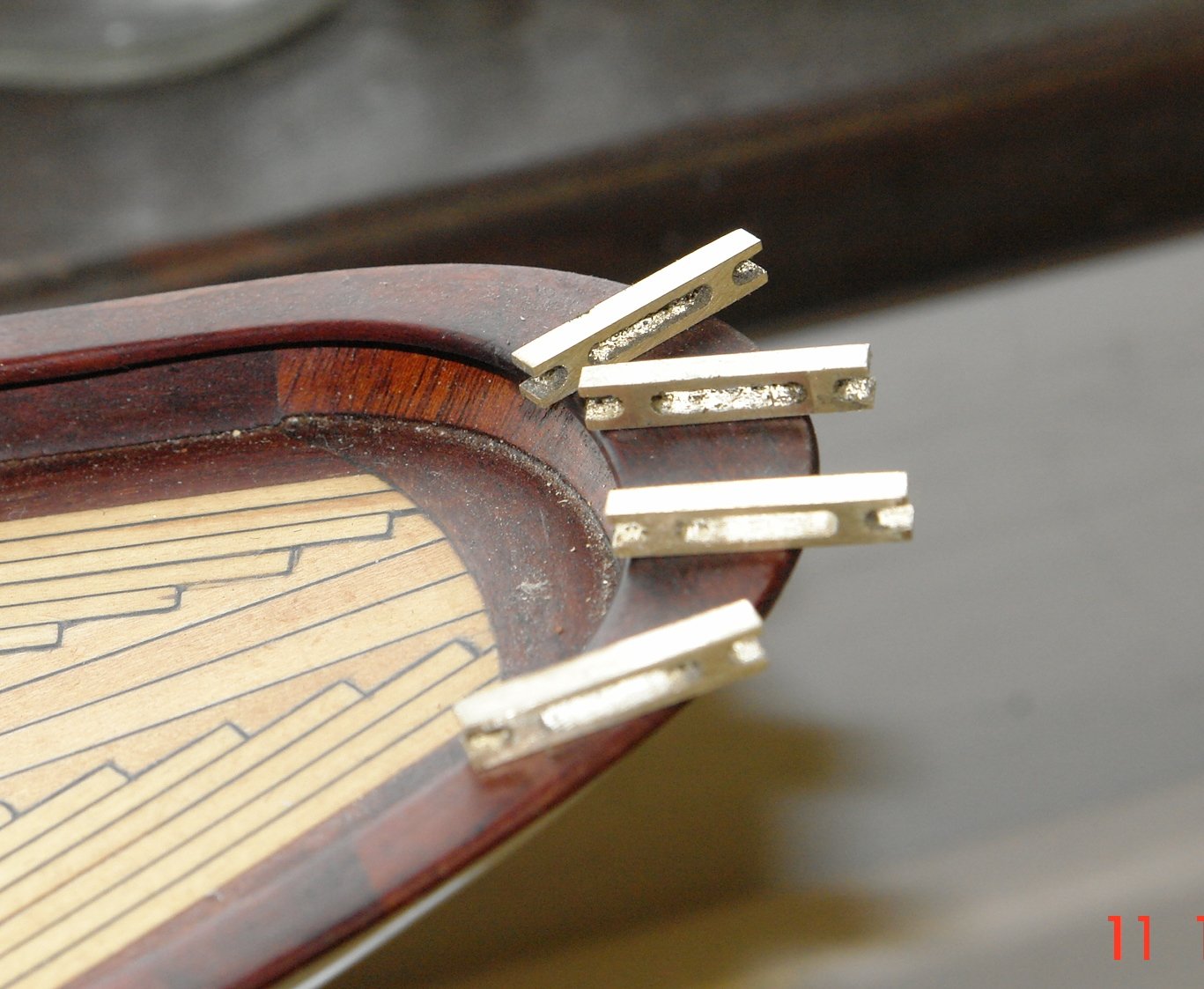
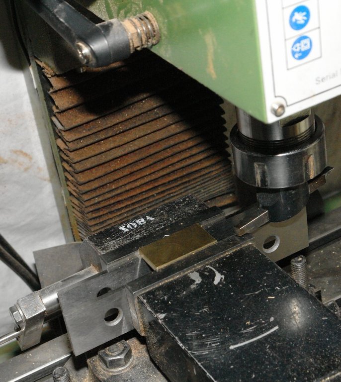
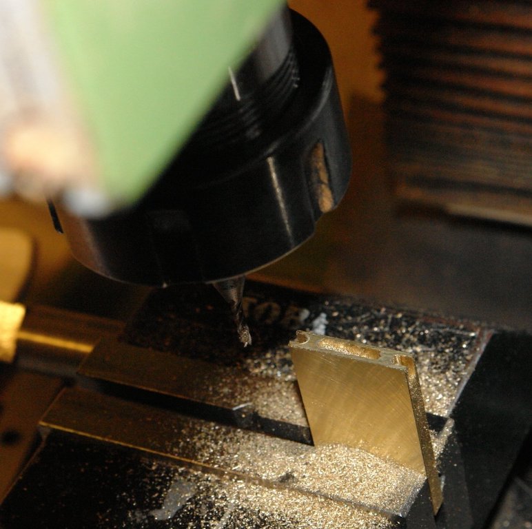
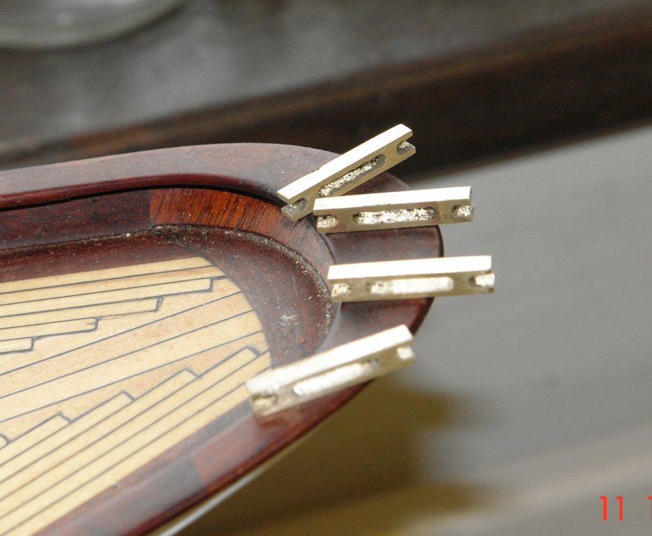
I spent today making a start on the fairleads. The forward fairleads are fairly standard while the rear fairleads have 3 rollers each. The fairleads are .875" long x .120" wide by .160" high. I made them from bar which was first machined to .875" wide by .160" thick using a fly cutter. The profile of the fairleads were first formed from a series of holes drilled along the length of the bar and then connected by a .080 diameter end mill. The fairleads were then cut from the bar using a slitting saw. Just to be a bit confusing the dimensions were worked out in millimetres. The corners were then cut off to give the finished shape (the top has still to be cut) Mounting holes and holes for the rollers were then drilled.


- 882 replies
-
- 15
-
-
Hello Bob, What is nice about this era is that the little ships are so elegant. They actually look like ships unlike the vessels of today. I think she will make a lovely model.
-
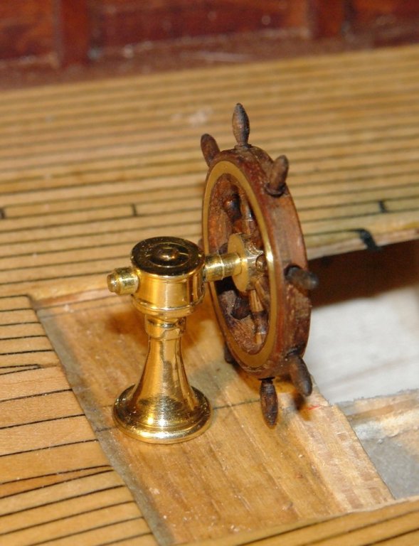
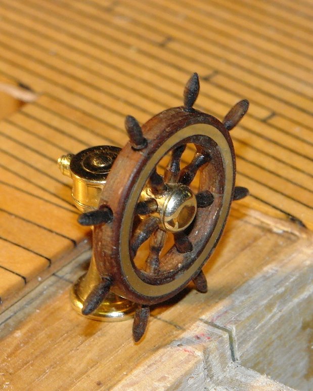
Pat, Per, Bedford, John. Glad you liked it and thank you for the positive feedback. A couple of final shots now with the wheel attached to the finished shaft / pedestal. It looks a deal more delicate at its real size. The photos make it look much larger than it is.