KeithAug
-
Posts
3,980 -
Joined
-
Last visited
Content Type
Profiles
Forums
Gallery
Events
Everything posted by KeithAug
-
 An impressive piece of lumberjacking😁
- 454 replies
-
- 3
-

-
- Union Steamship Company
- Stepcraft 840
- (and 3 more)
-
Eberhard / Tom - I think I will insulate the underside of the cover. I may leave the cover loose and do the big reveal it when showing people around.
-
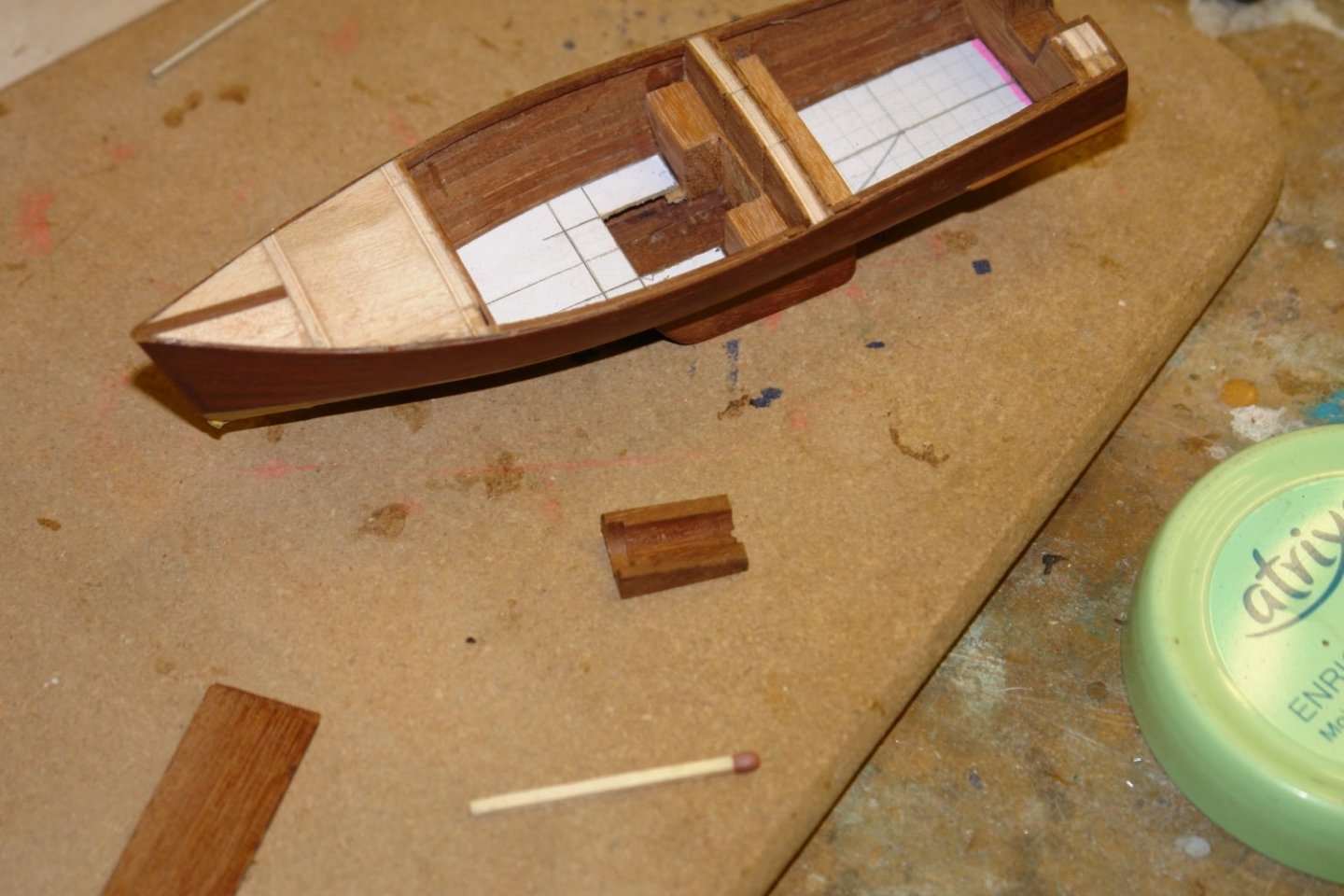
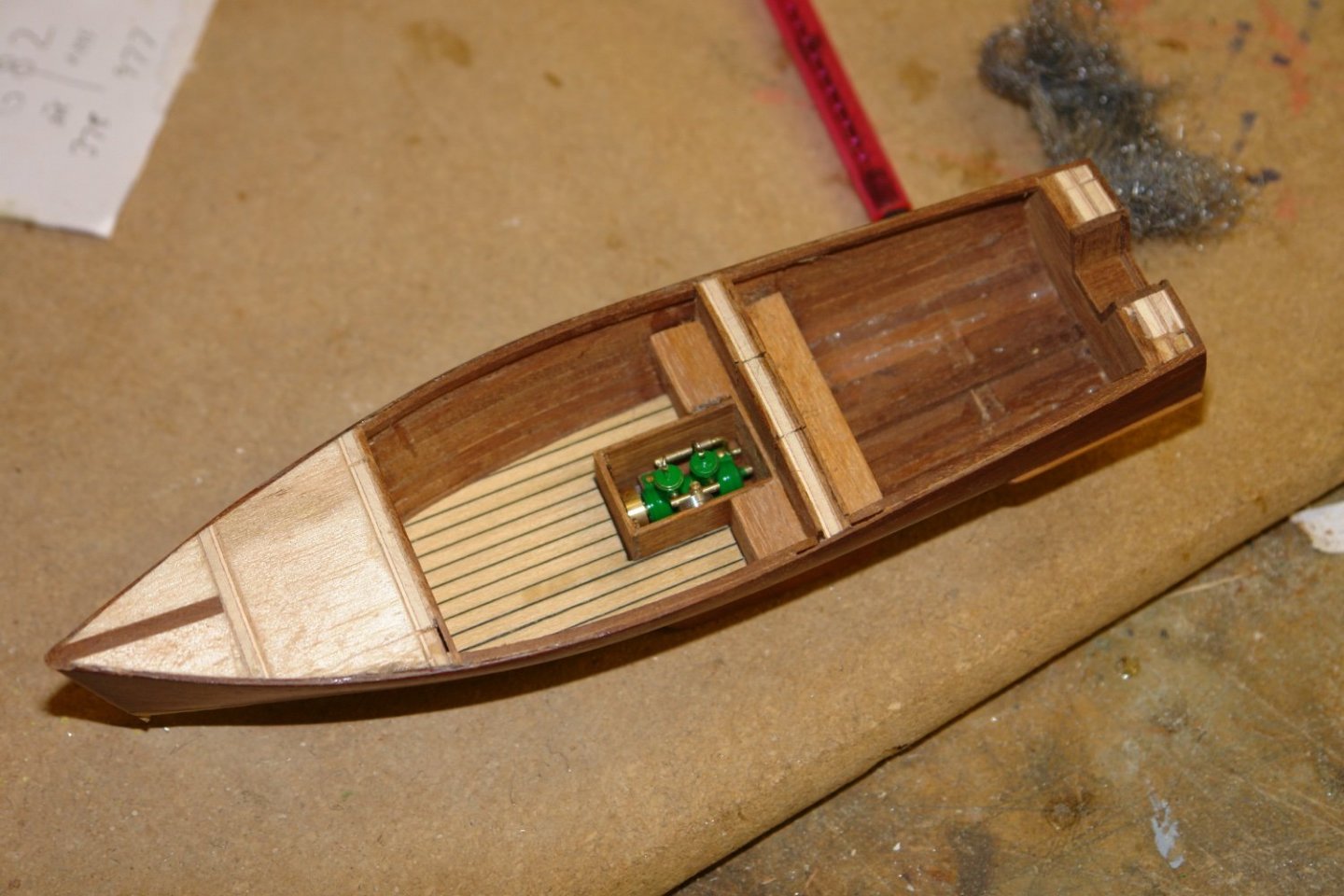
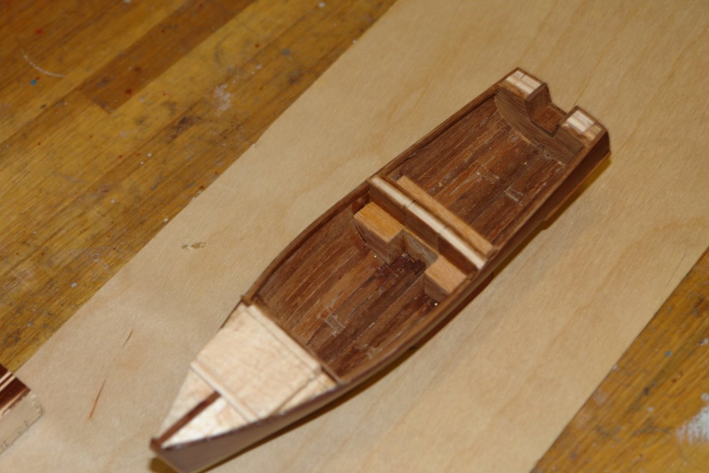
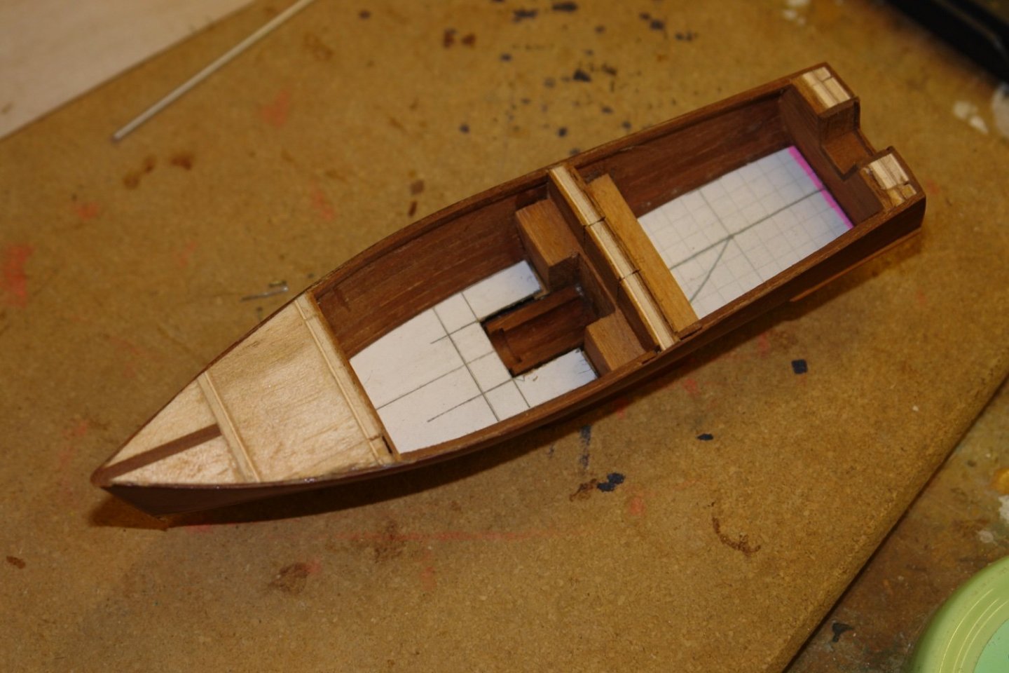
Eberhard - yes it is water cooled - the water pump is hidden behind the flywheel and the distributor is buried beneath the exhaust manifold. I forgot the oil filter though. 😁 Gary / Keith - thank you. Having finished the engine and its base I started to build the engine box in the hull - firstly installing the central bulkhead bench seats. The forward well deck was installed and the engine box was then built with the engine temporarily put in place. The engine was hidden by the box cover which provided a bit of additional seating. The frames on the actual launch are quite widely spaced and this was repeated on the model launch. The frames were made from mahogany which was steamed, bent to shape and then glued in position. The seating in the front well was then installed. The aft well deck was then installed.
-
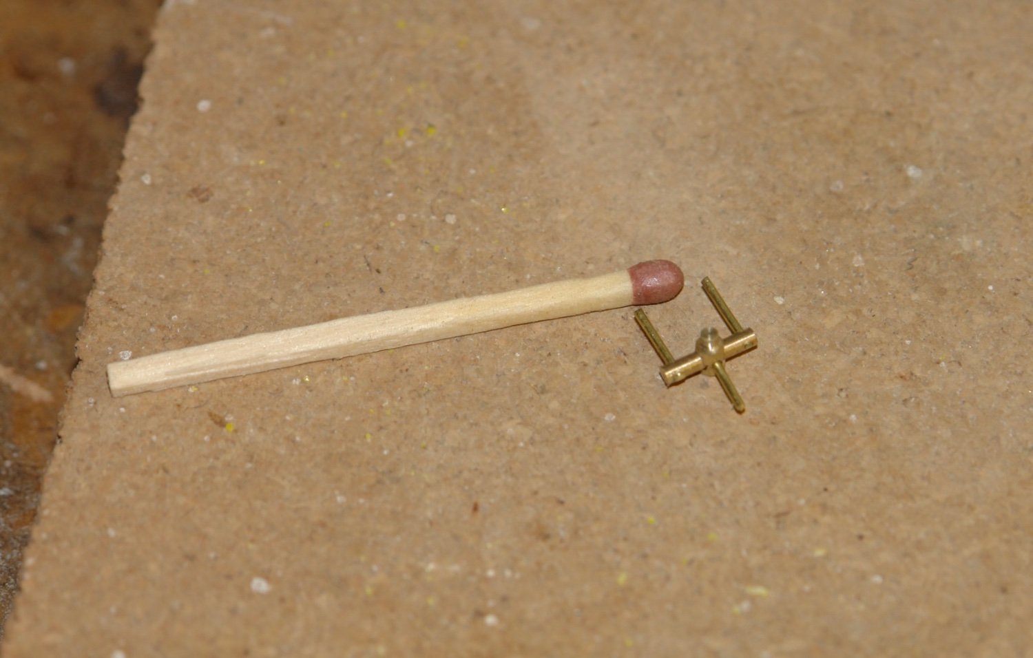
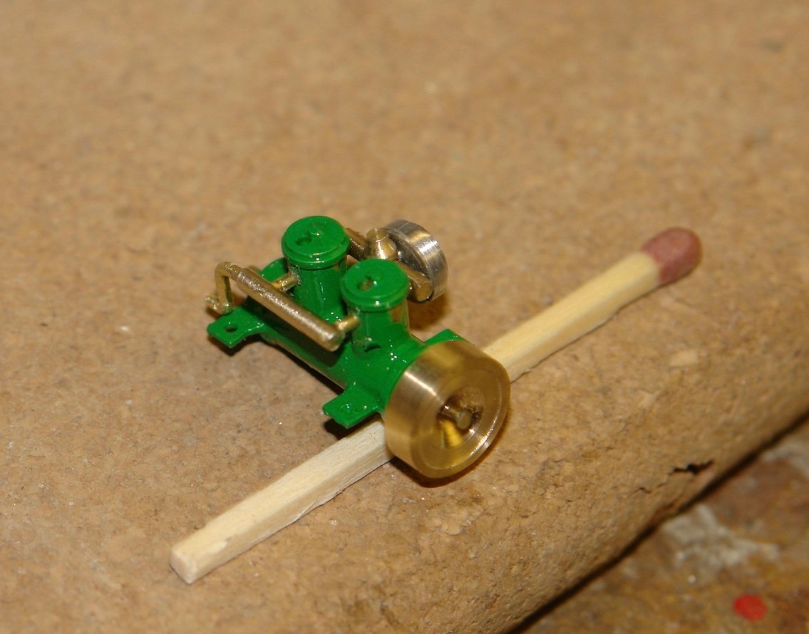
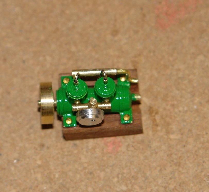
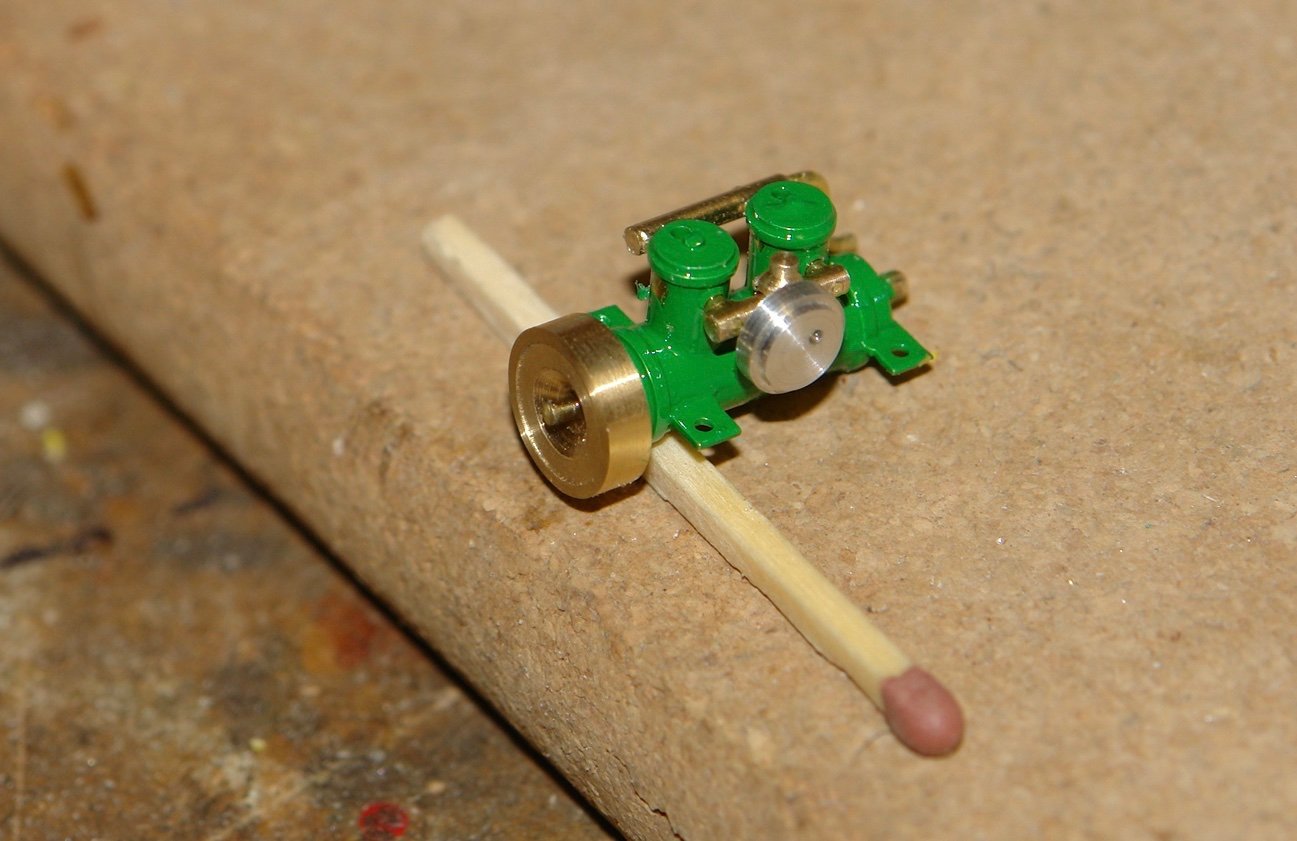
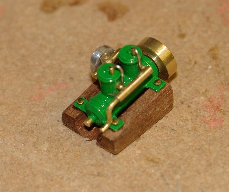
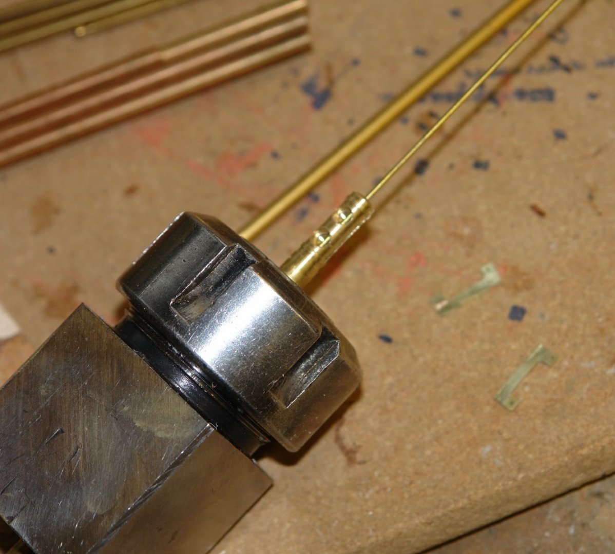
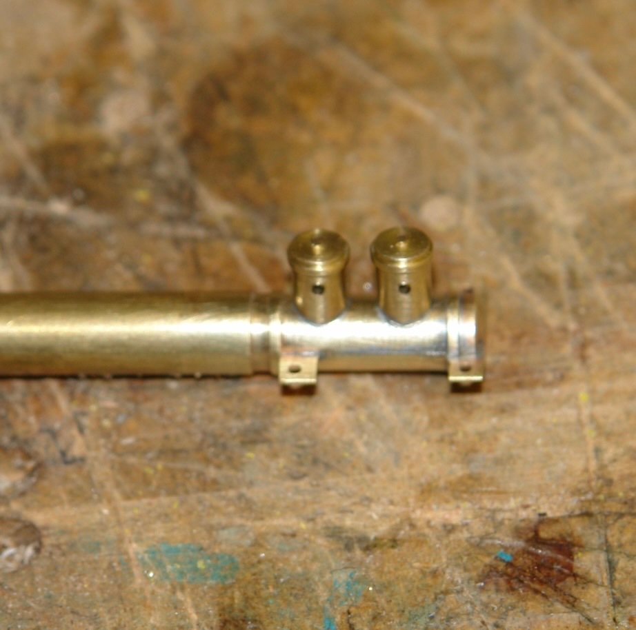
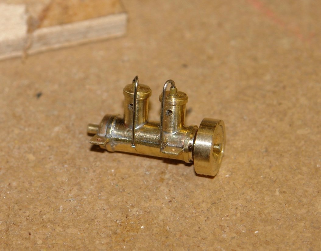
Thank you Keith, Gary, John, Pat, Hakan and Andy. Also thanks to everyone for the likes. I continued work on the launch - firstly by completing the engine. The inlet manifold with carburettor was made from brass rod. The air filter housing was then made from a piece of aluminium rod. I then mounted the inlet and outlet manifolds and painted the body. The engine support was made from a piece of mahogany cut to a taper to align the engine with the prop shaft. The spark plugs are also installed.
-
Hakan, glad to see you back in the workshop even if it is only an interlude between the daily IV treatments. Noting Vaddoc’s comment I think it unlikely that the average medic would be as pedantic about their craft as the average msw builder. Your framing and keel are looking very good. Sometimes slow and sure is the best strategy for both model boats and convalescing builders.
-
Mike, I Love the masts, very nicely done. I’m not quite sure what the benefits are of the tailstock Chuck. Why wasn’t it possible to restrain the tailstock end of the mast using a live centre?
-
Eberhard, the 2 steering positions are very exposed. Was there an alternative protected steering position? The forward steering poison must have been a bit exciting when the gun was fired. Lovely detail.
-
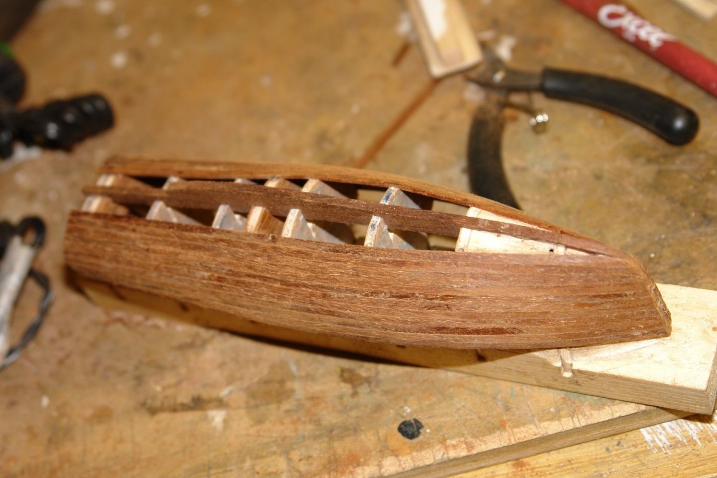
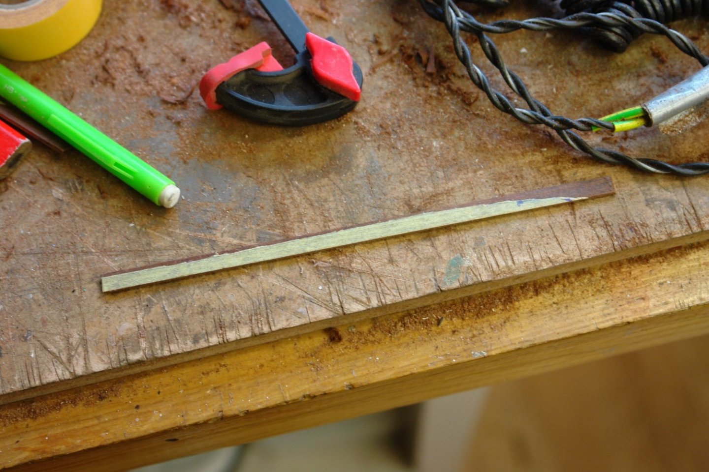
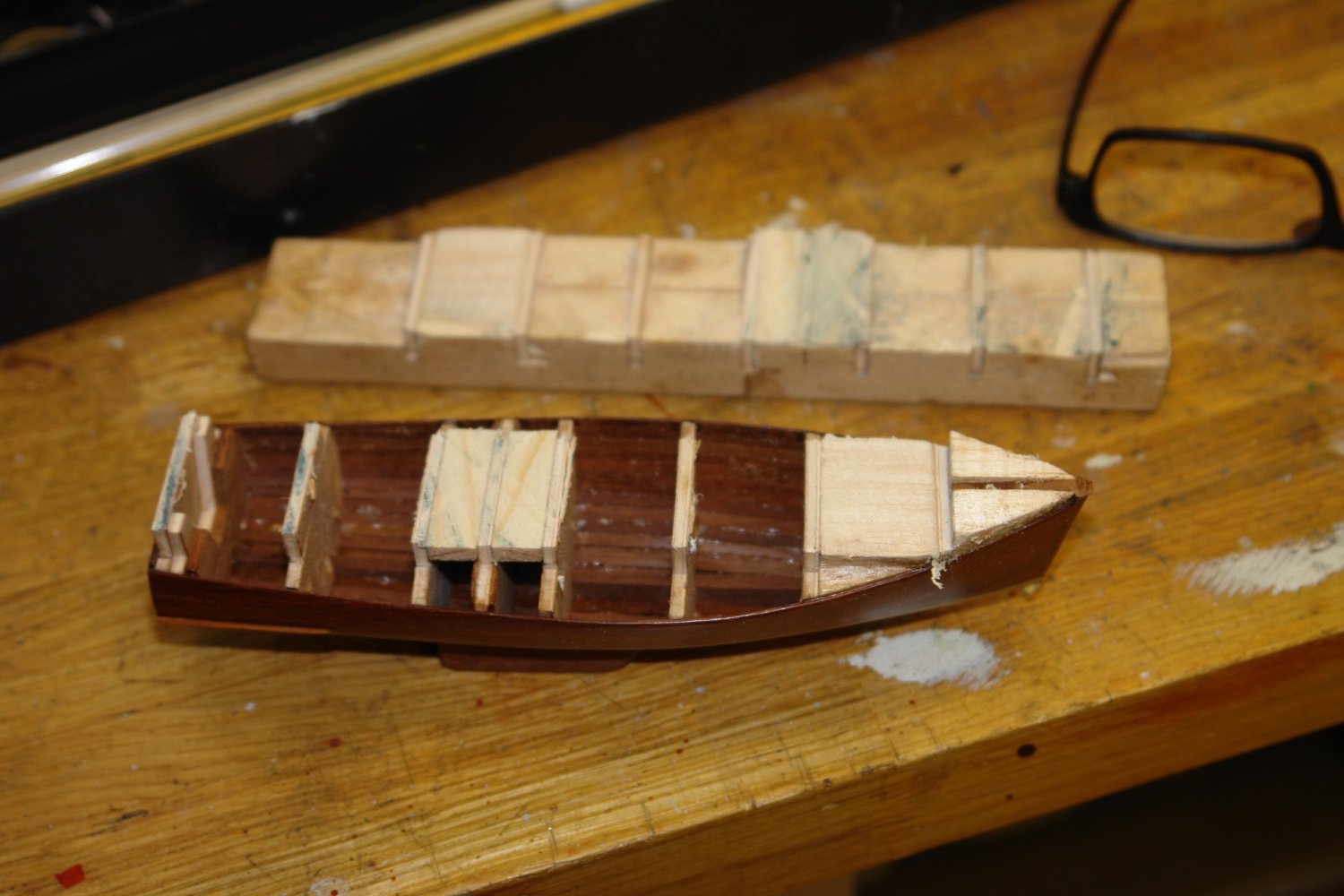
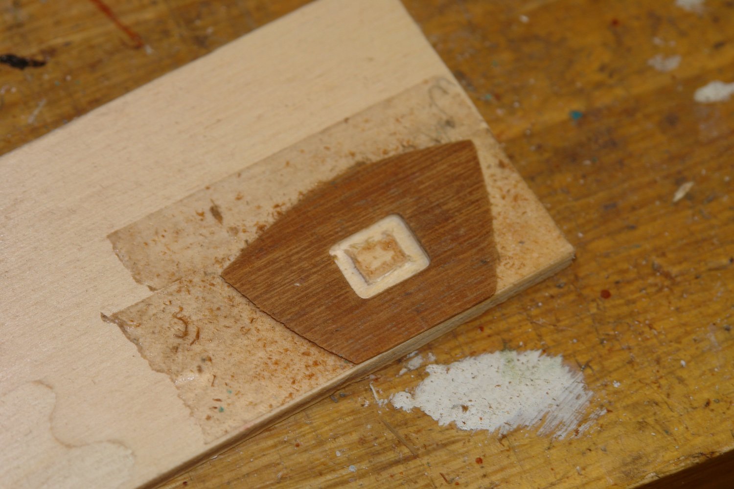
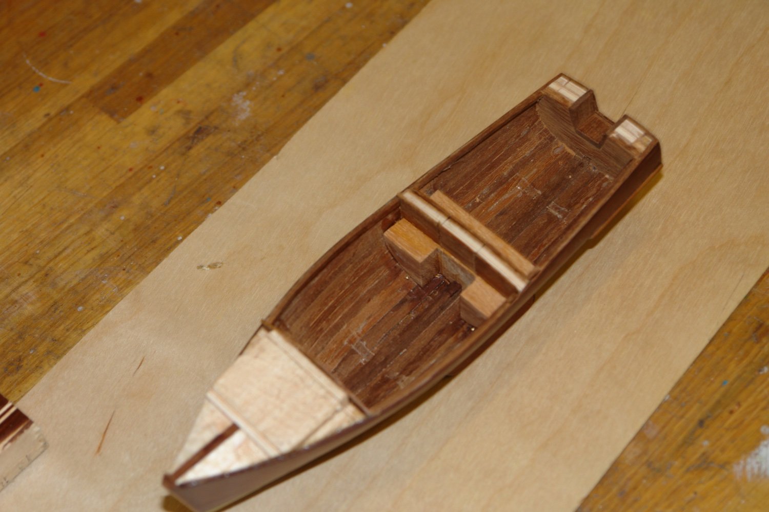
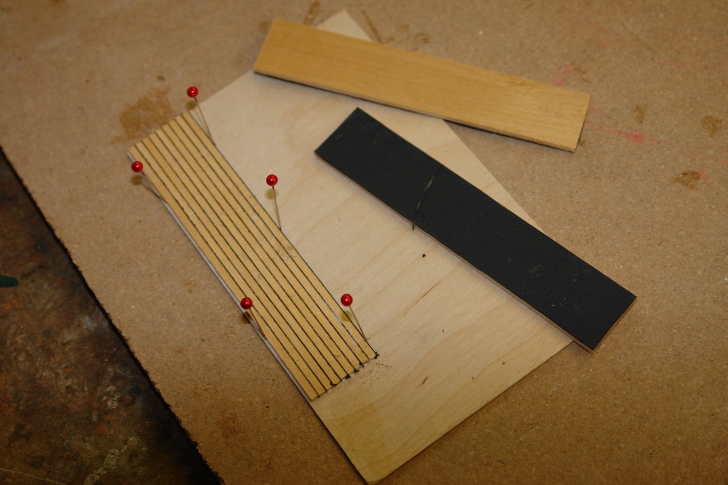
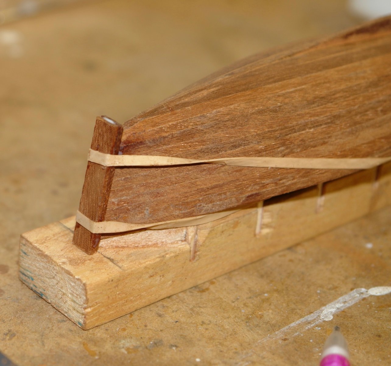
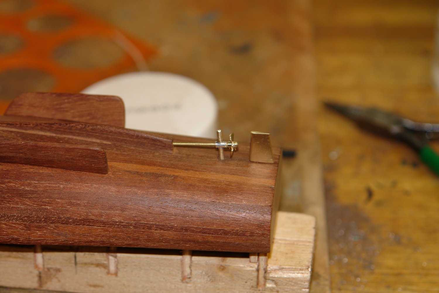
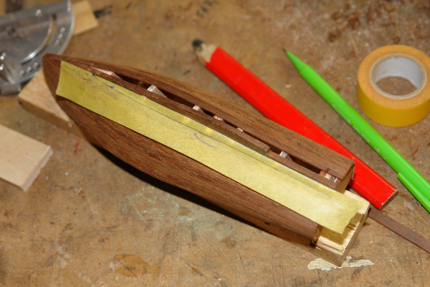
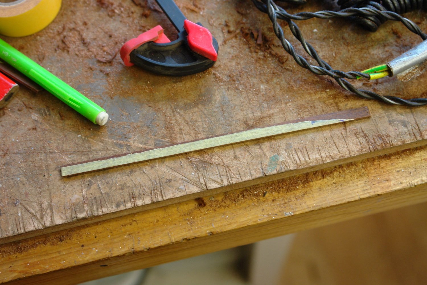
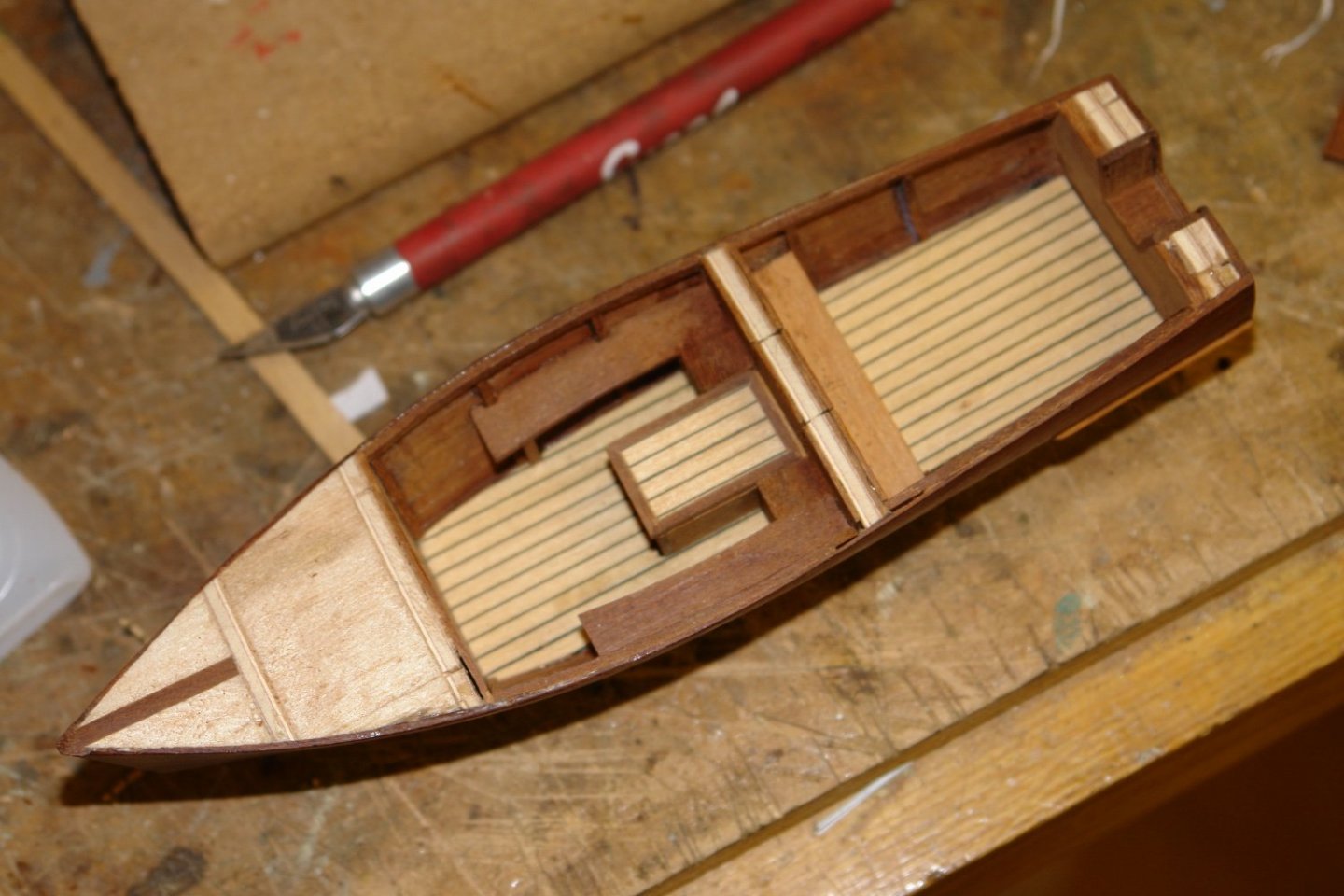
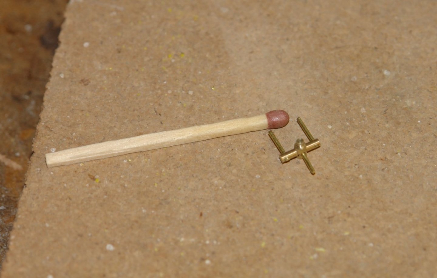
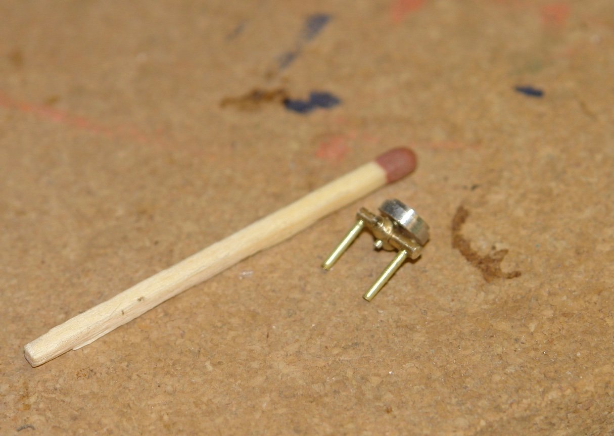
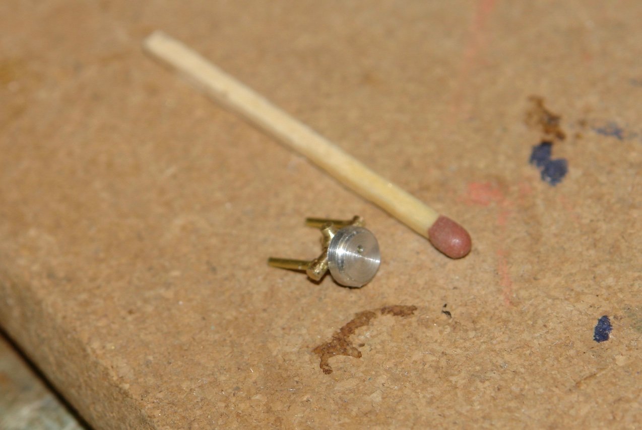
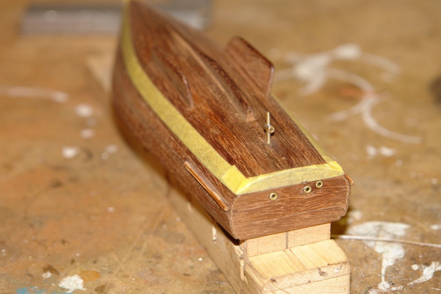
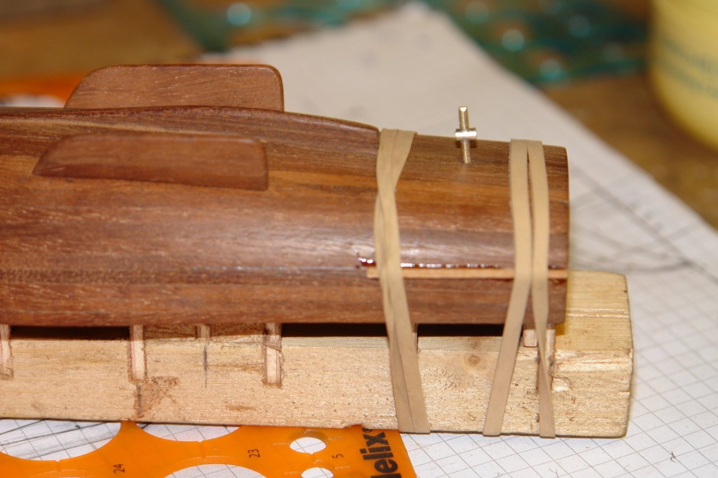
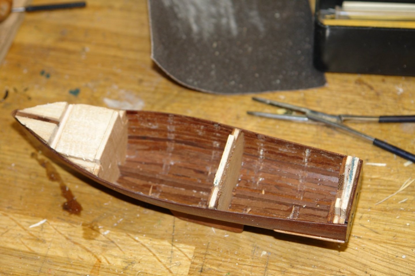
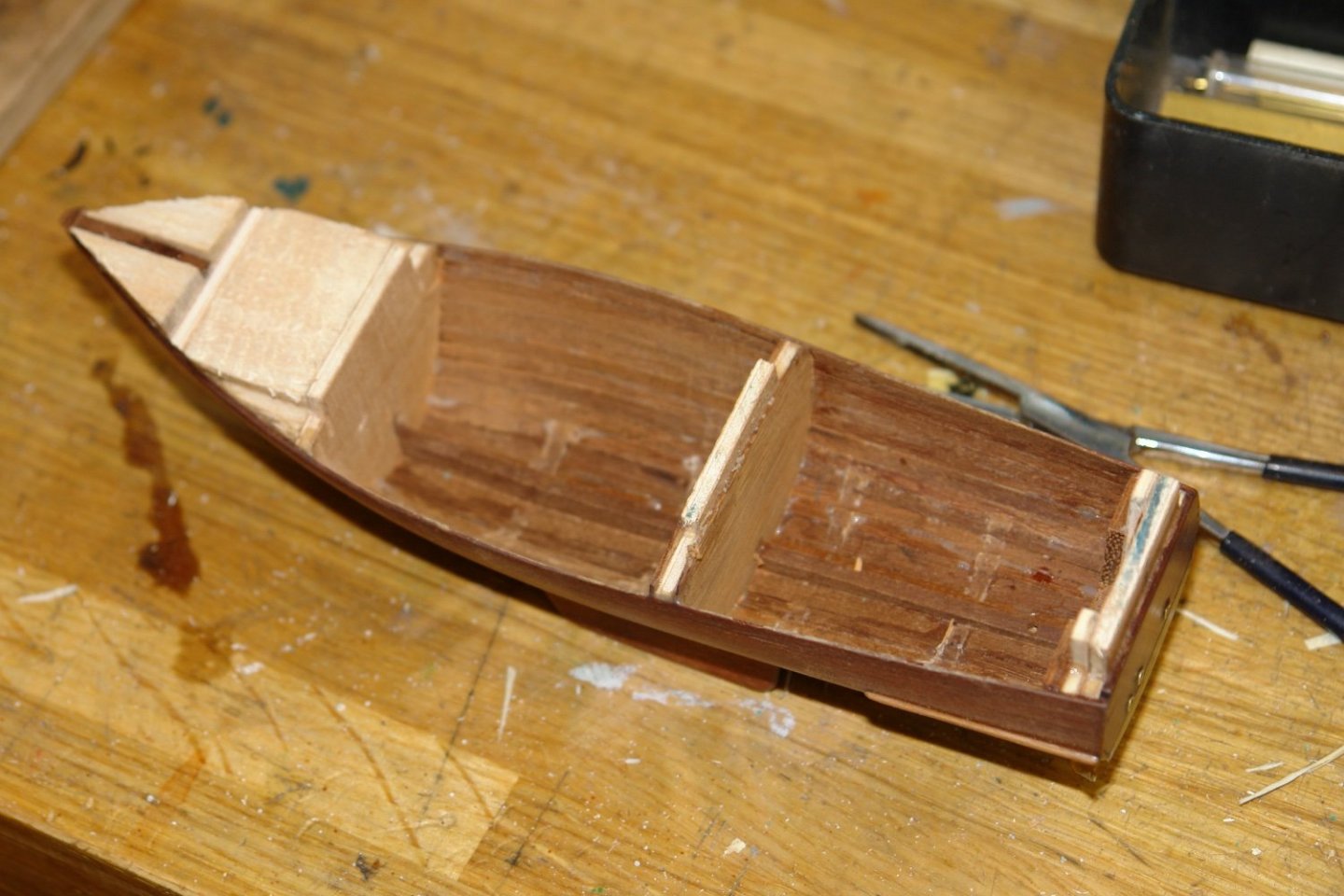
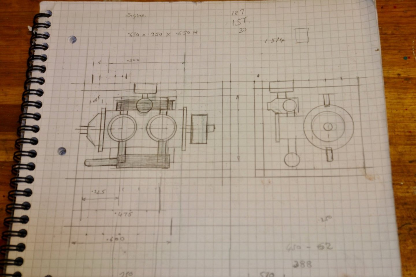
Tom - I kept the machining fairly simple and finished the shape with a needle file before twisting the blades. Not too professional a job but sufficient at the size. I agree Mark - Germania has a RIB for that. Thank you Michael and Keith for your comments. I haven't been doing much of late - other issues have been distracting me from model making. However here is a modest update. A pair of rubbing strips are mounted at the stern. These were held in place with rubber bands before being glued with CA. 3 holes were drilled in the stern - one for the exhaust and 2 for the swimming platform step I then cut the hull from the building board. Then came the delicate task of removing the frames. Some had been "caught" by the planking glue but with a little delicate persuasion they came free. The hull by this stage was very delicate and light as a feather. I needed to do a bit of internal clean up and I did this with a scraper. In the next photo i have just made a start. I then needed to start adding some of the internal detail such as the forward bulkhead (with locker cut out). Then the seating on either side of the central bulkhead. I also added thin reinforcing strips on the inside of the hull at deck level. This made the hull feel much stronger and gave me a bit more surface for gluing on the deck edge planks. Finally I thickened the stern bulkhead and cut out the access way to the swimming step. The next job was the deck planking. I used my now (much preferred) method of making the planks. I cut a strip of wood with a thickness equal to desired plank width. I then glue card to the wood and when dry slit off the deck planks - already with the caulking attached to one side. The planks are then glued together. This is a very simple neat and quick planking method. I then spent a bit of time making the templates for the decks. I also sanded the balsa blocks at the bow ready for the planking. I then started to think about the engine. It needed to sit within a engine box measuring .650" x .650" x .950". The real launch probably has a small Volvo Penta diesel but my launch is going to get something which looks a bit more traditional. I decided on a twin pot petrol engine of 1930's vintage. It has an air filter and caburettor which sits abreast the inlet manifold. The engine is cross flow with the exhaust manifold on the opposite side. The reduction gear box is at the rear and this is attached directly to the prop shaft. A large flywheel sits at the opposite end. This of course is a complete flight of fancy. The crank case is made for a piece of 1/4" brass rod. It is slotted to take the engine mounting flanges and two holes are machined to mount the piston sleeves. A central hole (right hand side) is drilled to take the prop shaft. The mounting flanges and the piston sleeves are then soldered in place. The inlet and exhaust holes are then drilled in the piston sleeve. The block is then parted off from the bar stock and a flywheel is attached before fitting the spark plugs. More to follow.


-
Gregg, I just use PVA glue - not thinned. I lay the first plank on a line of glue and hold it down with notice board pins. Once dry I put another bead of glue alongside the plank, offer up the next plank and hold it down with pins. in any event my advice would be to do a few experiments on some scrap material first.
-
Eberhard - I tend to agree. I am not sure what the rationale is for their design. They may be a little deep but they need to be deeper than the keel. I guess it that is more to protect against floating debris than rocks.
-
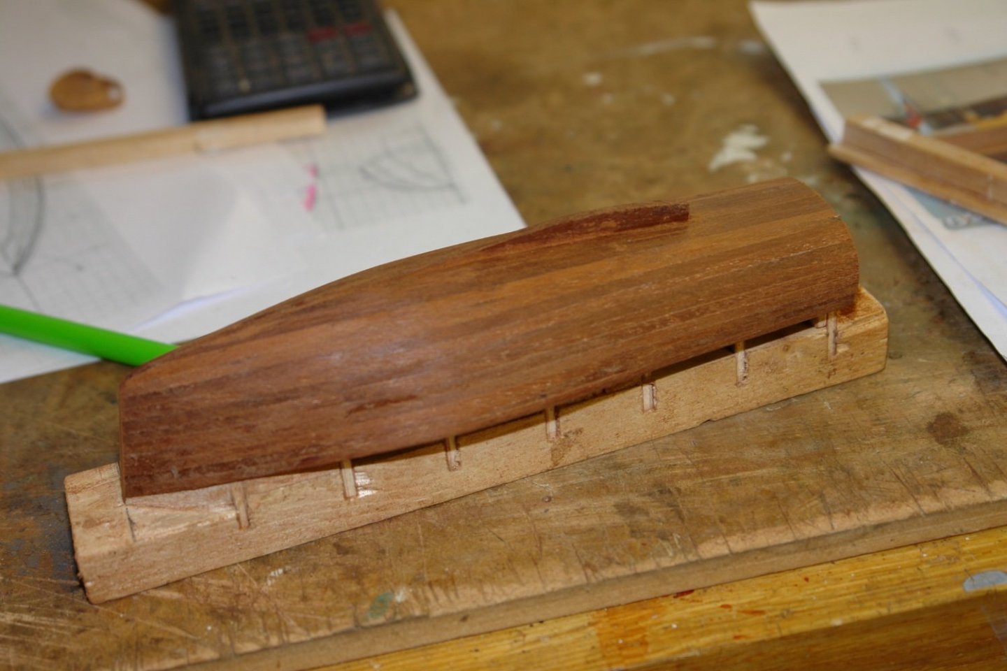
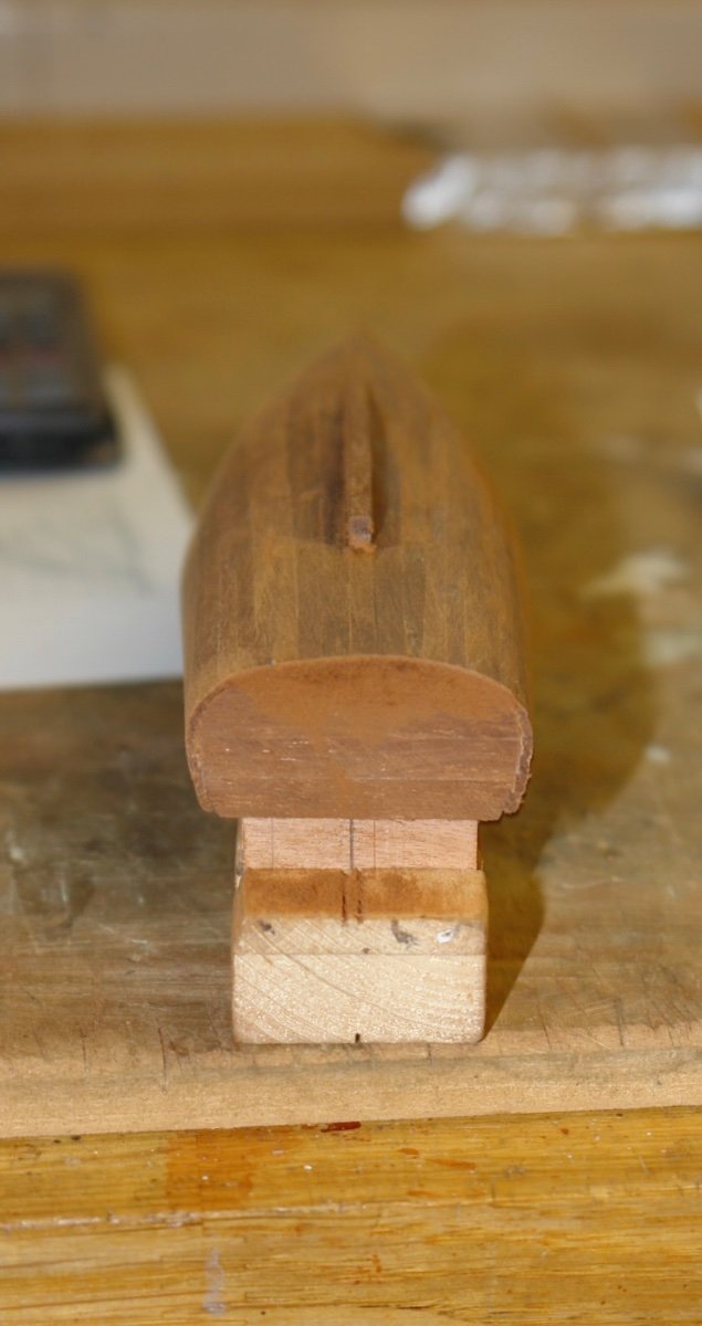
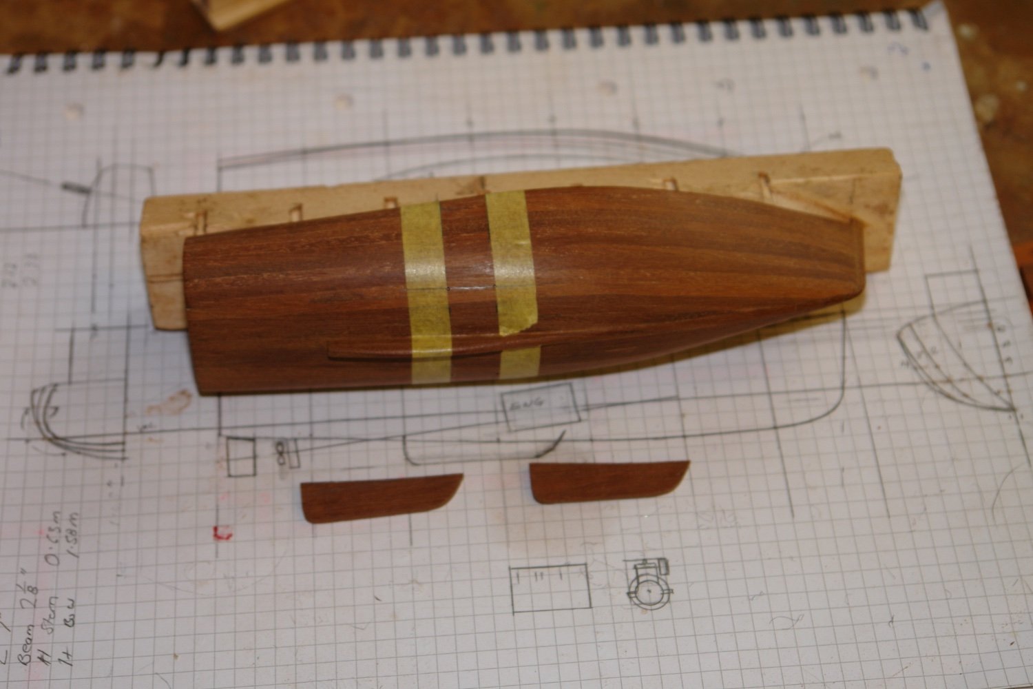
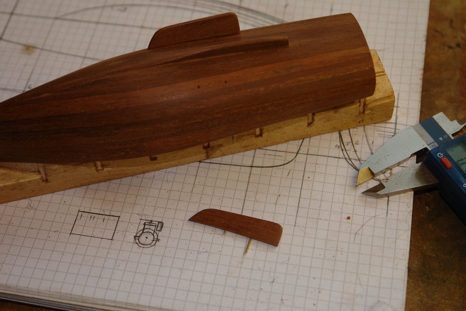
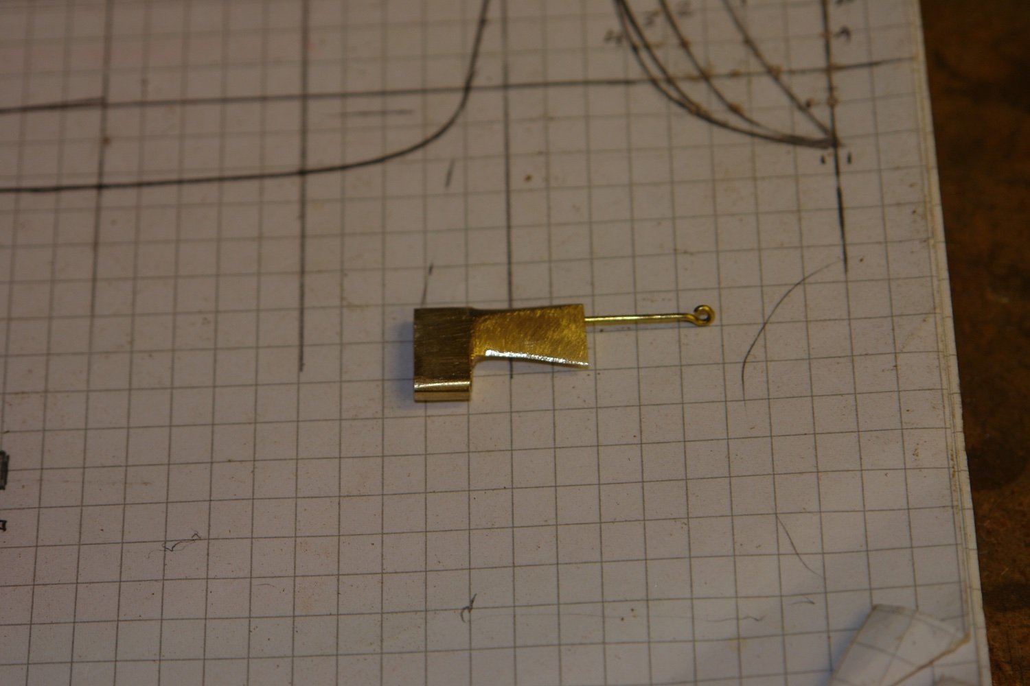
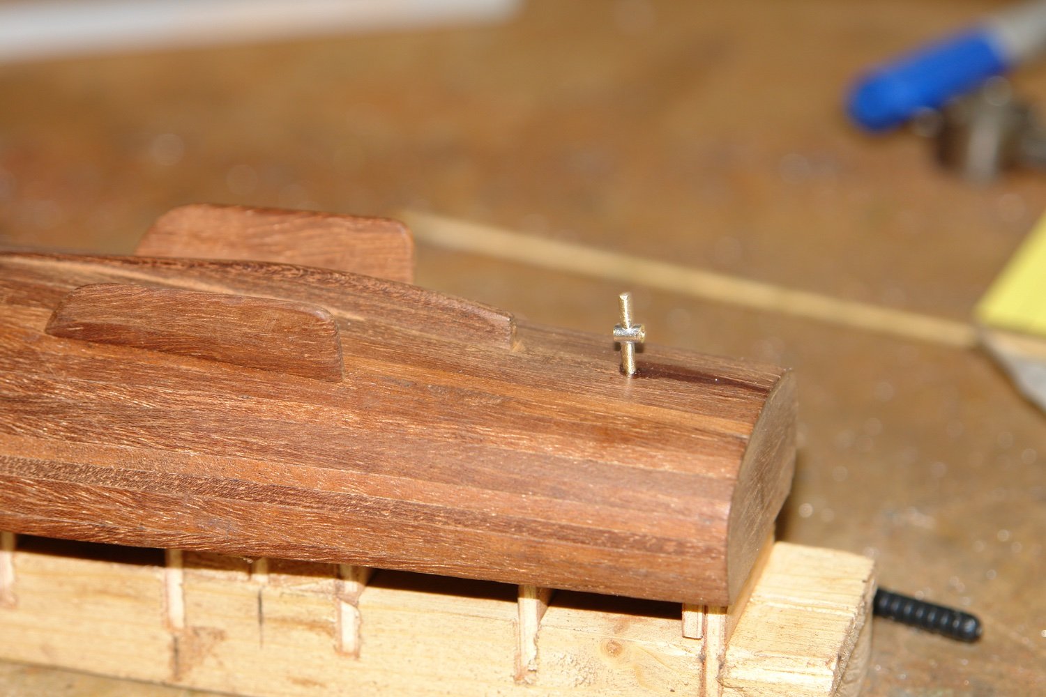
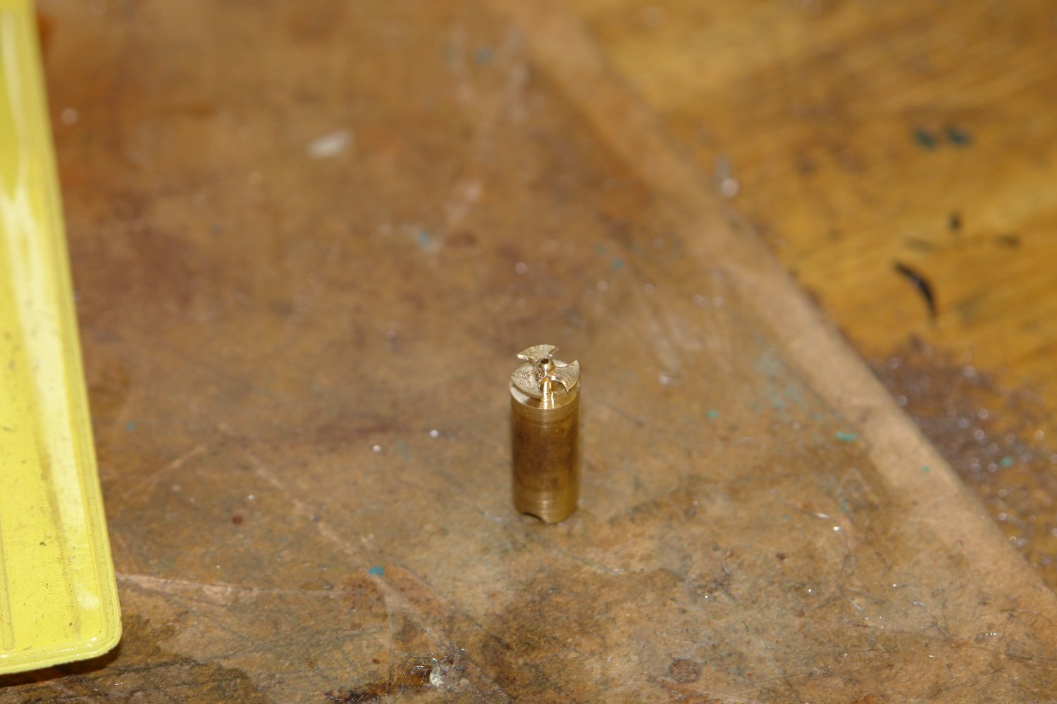
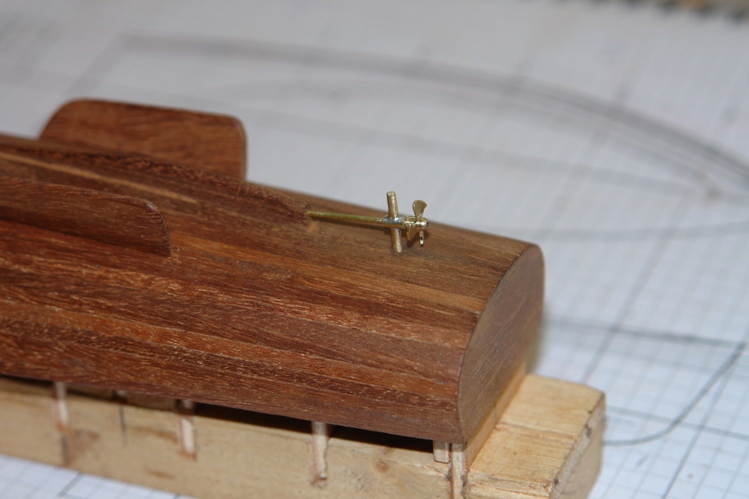
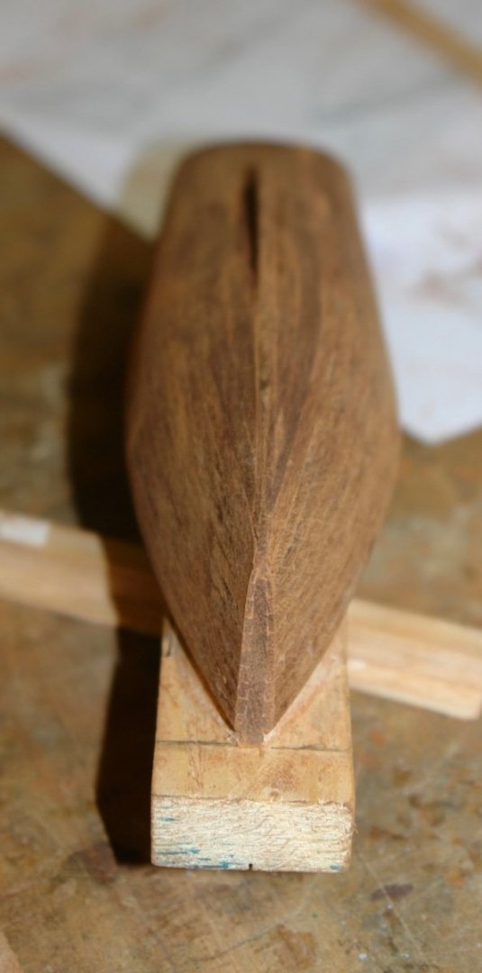
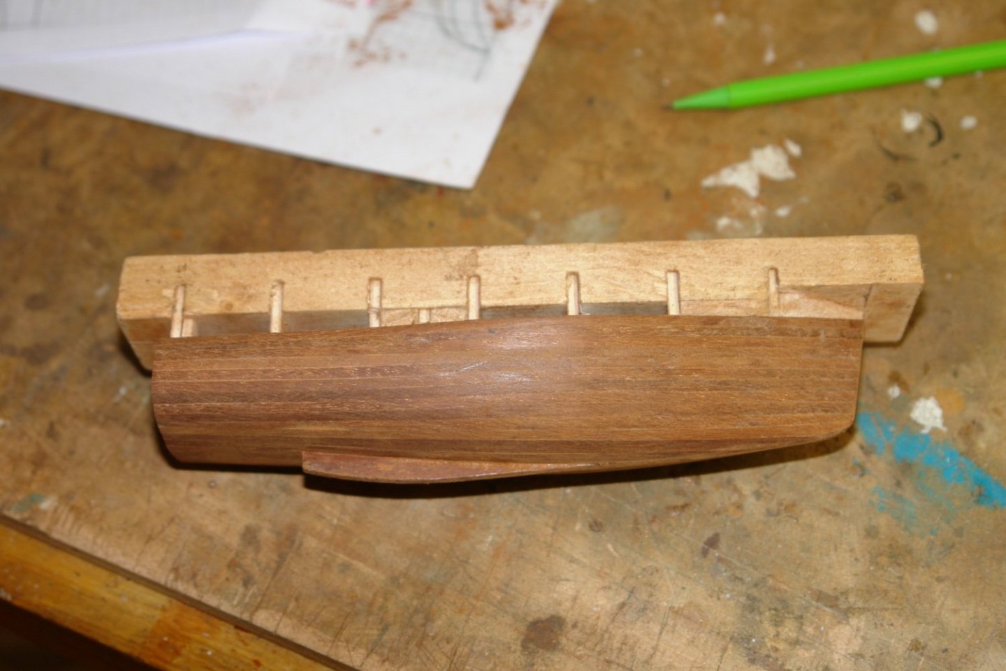
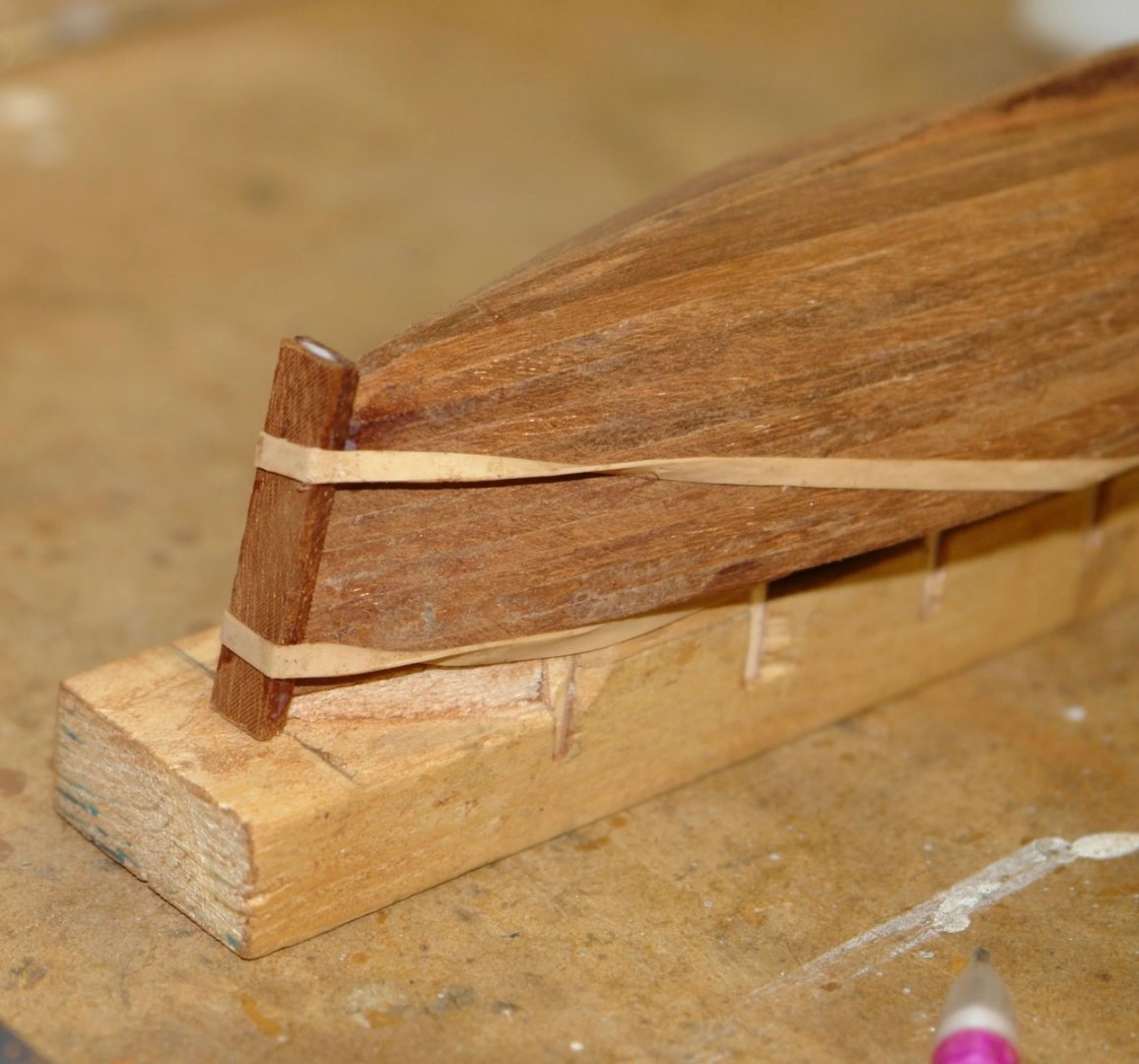
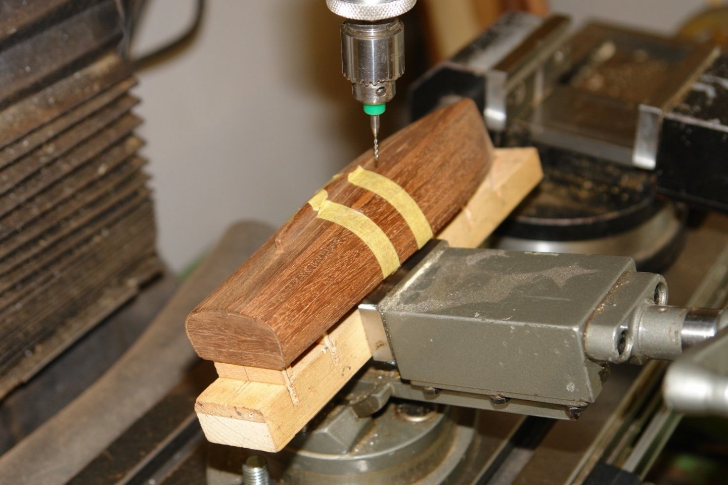
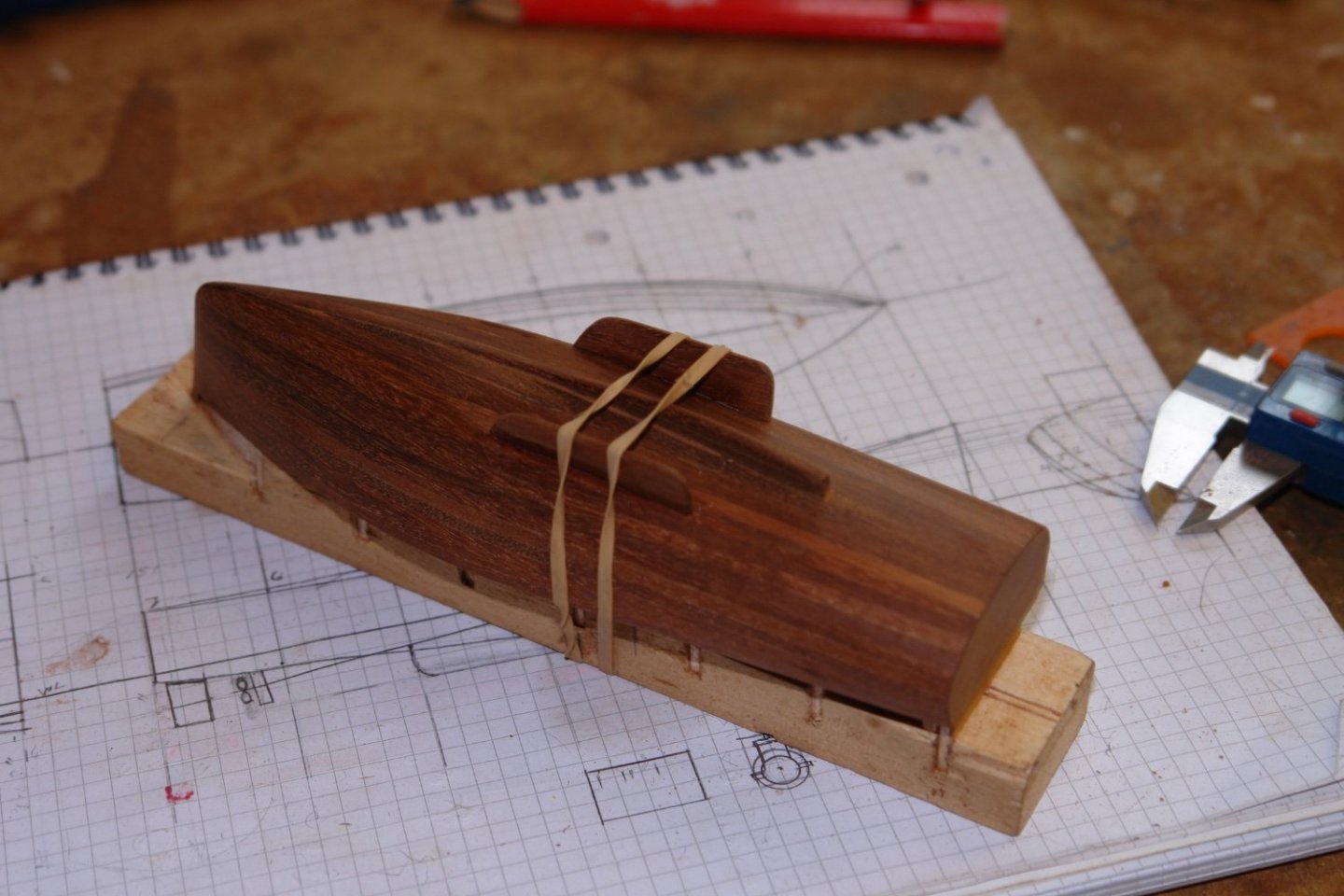
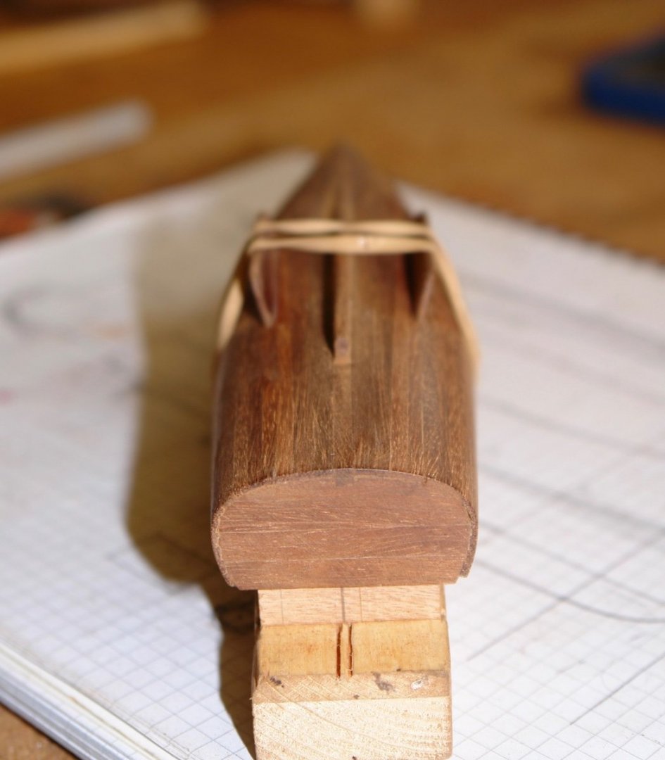
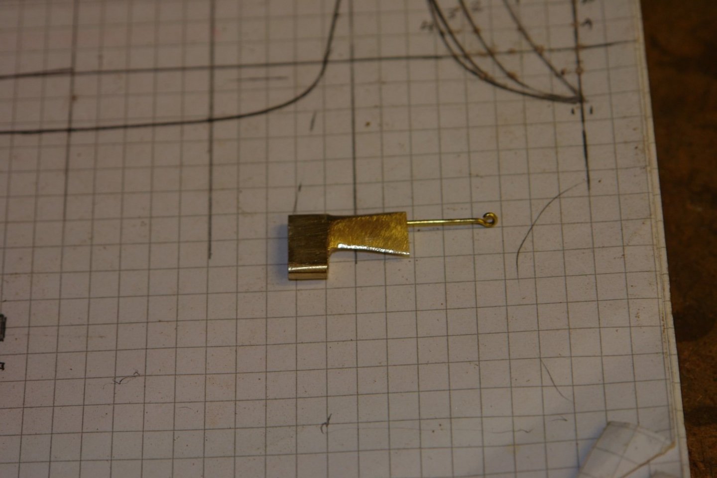
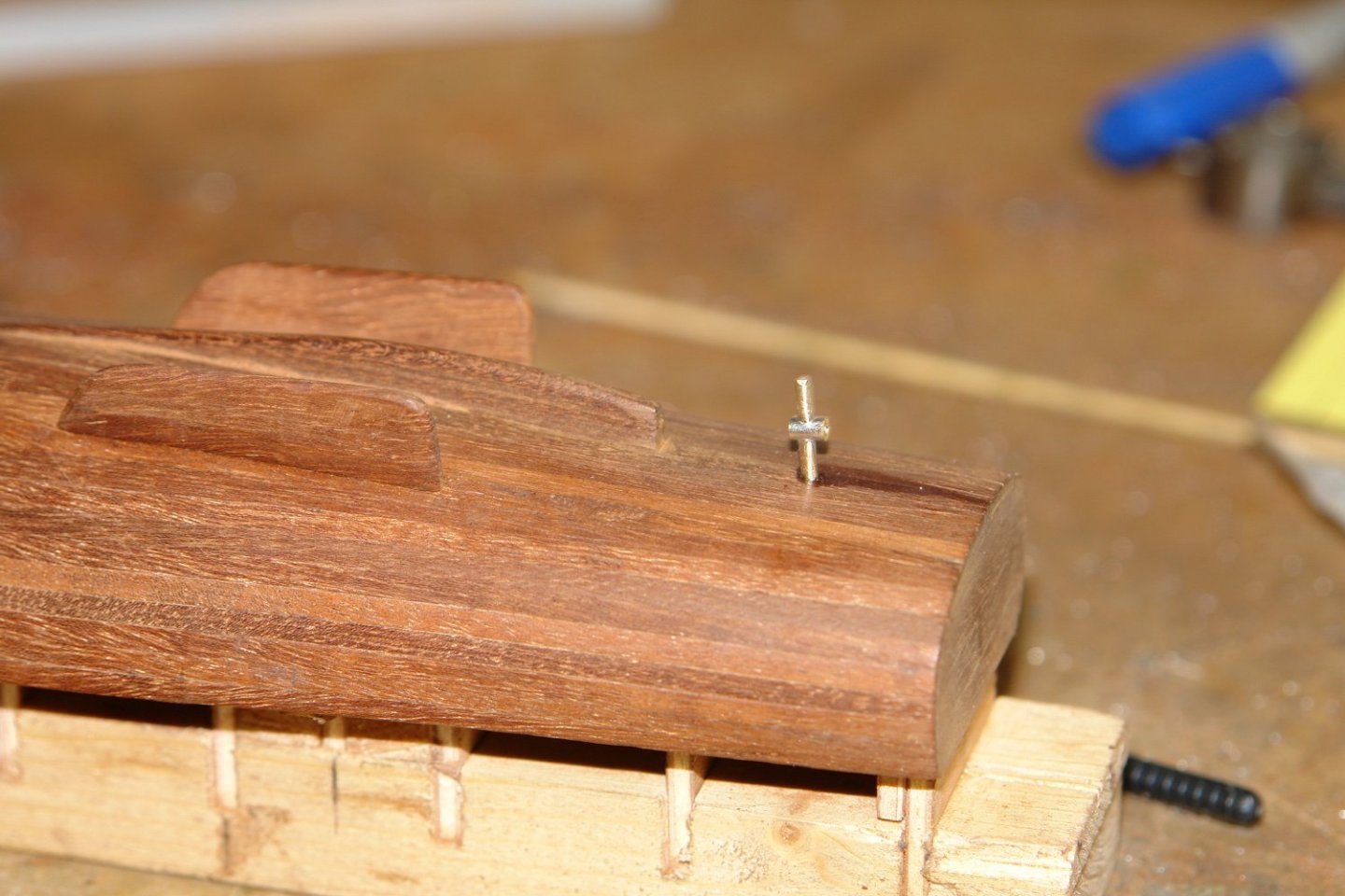
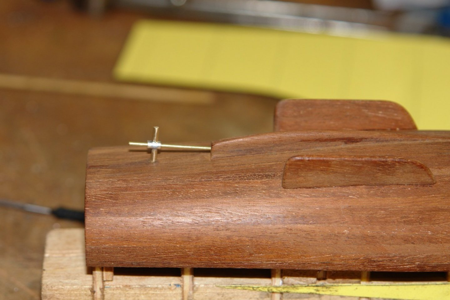
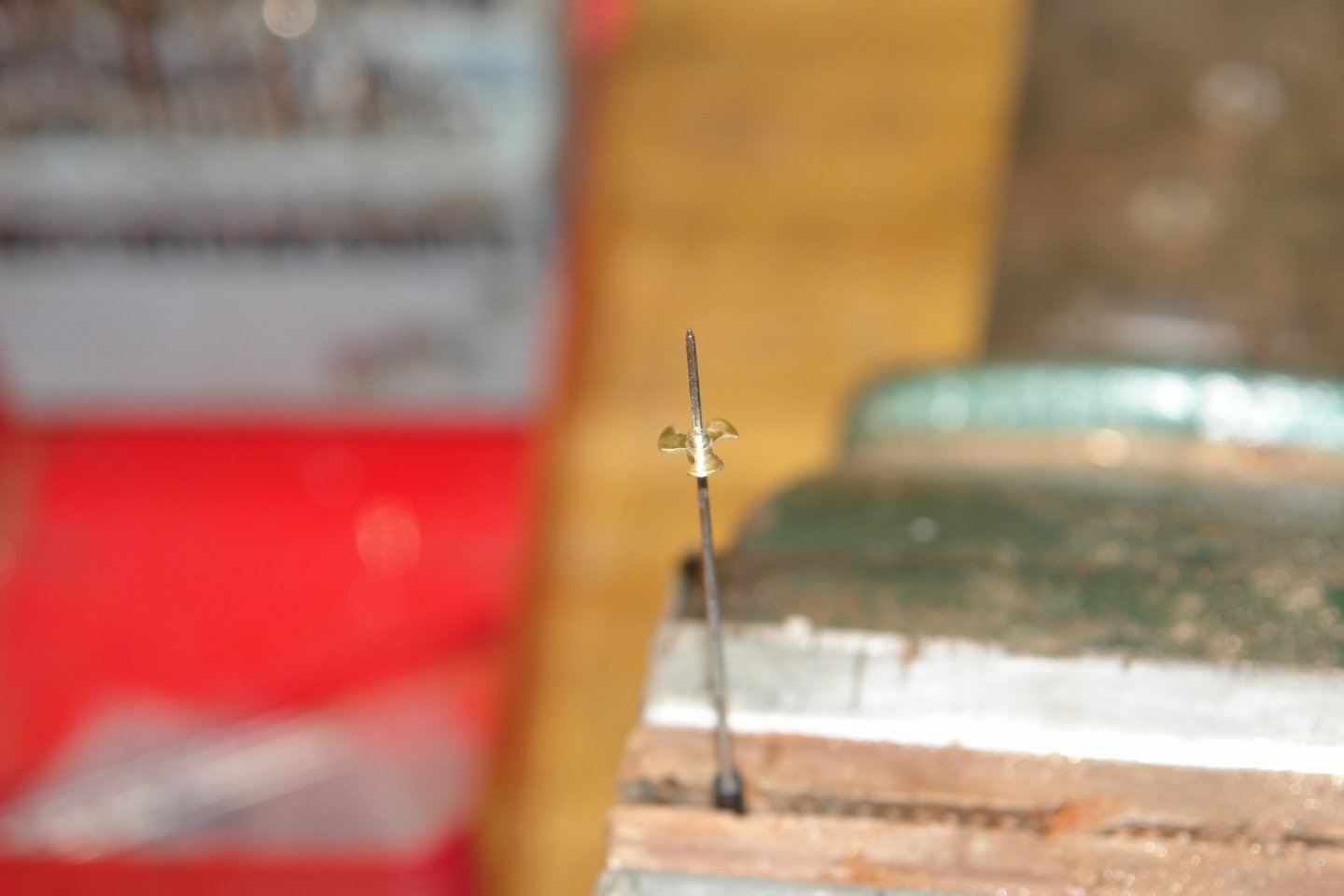
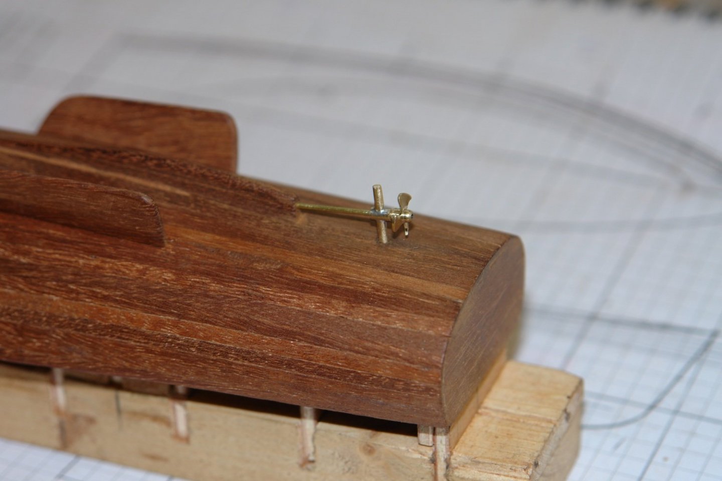
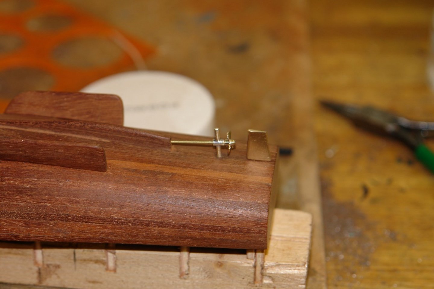
Thank you Keith, Ken, John, Michael, Garry and Richard. Your comments are always welcome. I haven't had a very productive week due to other priorities. I did get a few hours over the weekend to make more progress on the launch. I started by sanding out the remaining dimples on the external surfaces of the planking. I didn't sand through anywhere which was a bit of a relief. I also sanded away the plank ends at the stern. I then set about sanding the stem flat in preparation for adding the stem piece. I then glued the stem piece in position - held in place by a couple of elastic bands. This piece was then faired into the hull. Next came the pair of bilge keels, I decided to mount these using location pins of .040" wire. I marked the position of the pin holes on the hull using masking tape. The holes were then drilled at the correct angle using a tilting vice. The bilge keels were cut out from strips of mahogany before being shaped to the curvature of the hull. The keels were then drilled and the pins fitted. Finally the keels were glued in place - again held with rubber bands. Next came the rudder - filed from a piece of brass bar. I also made the prop shaft bearing which has an extension to protect the screw. The prop shaft is a piece of .040" rod. At the size of the launch I didn't put an enormous amount of effort into the screw. I machined the rough profile into the end of a .312" brass rod - parted off the screw and finished the shaping with a file. I then temporarily fitted the screw and the rudder. As I said I haven't made a lot of progress.


-
I think you may be quoting from the standard play book.
-
Lovely job Hakan. Your build rate is pretty typical as far as I can tell but some seem to build at an unbelievably rapid rate. I prefer a more relaxed approach - its my age you know. .
-
Gary - Good tip. Now where did I park my time machine? Perhaps just better to remember it next time.
-
Gary - beautiful job on the frames ----------------------------- pity about the rivets😀.
-
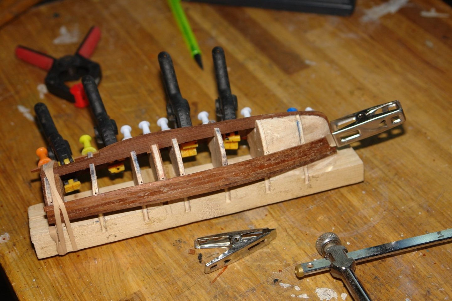
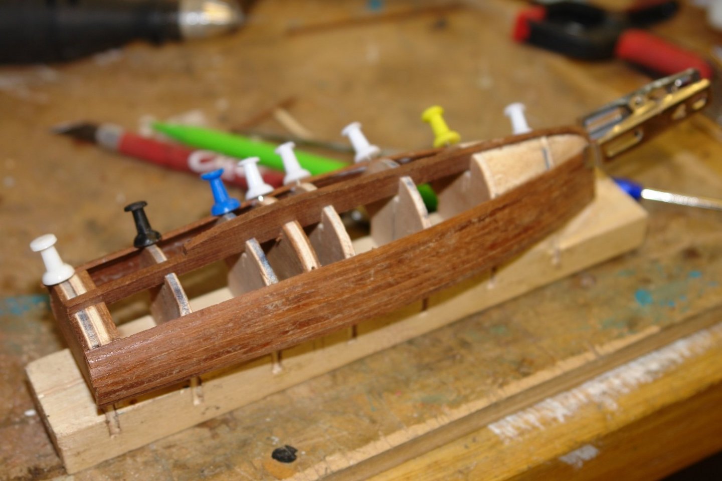
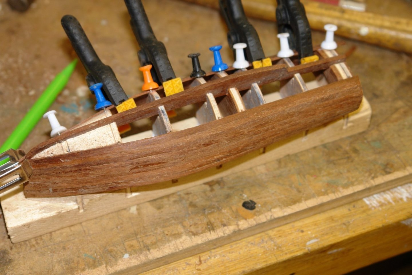
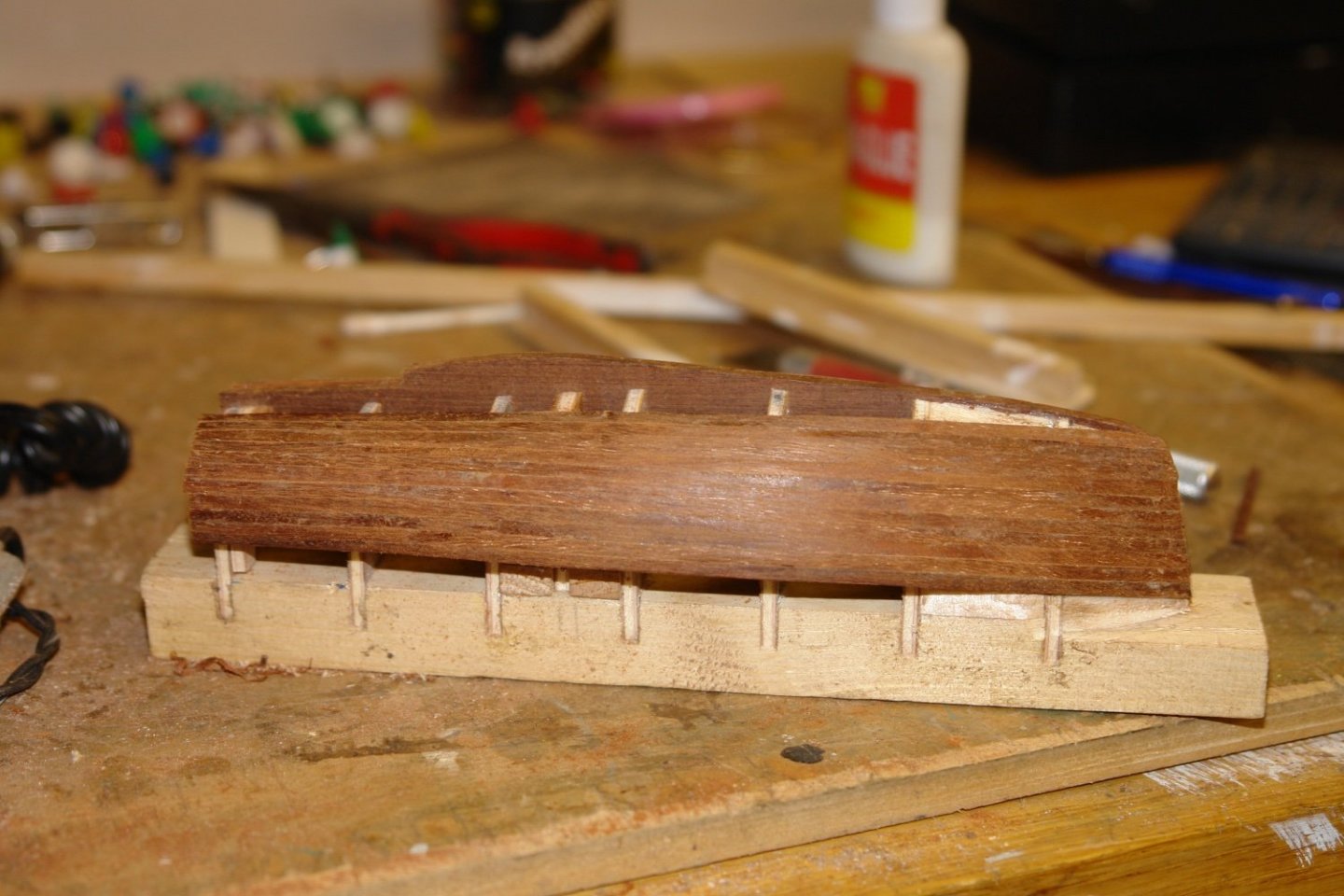
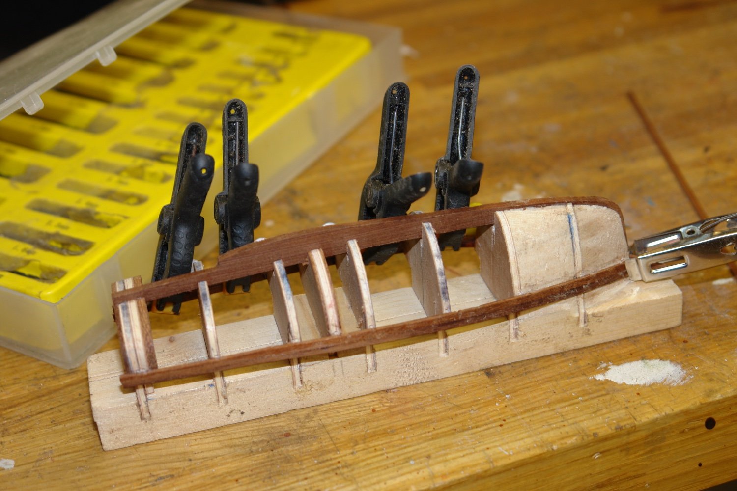
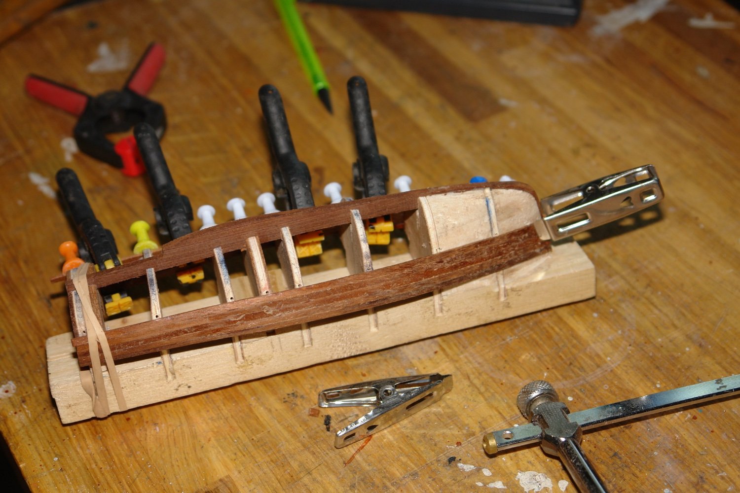
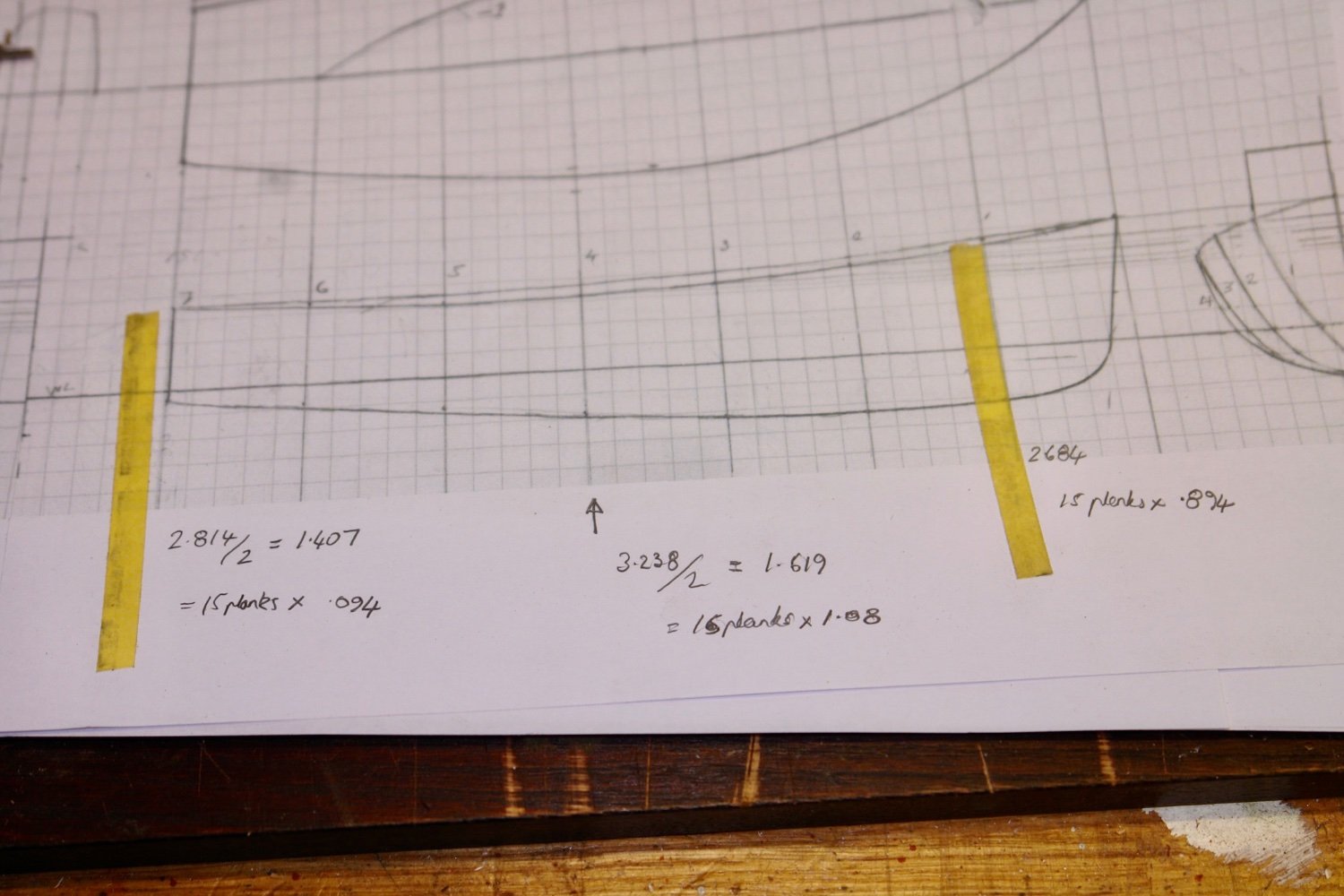
Thank you Pat and thanks to everyone for the likes. I resolved to plank the hull using a professional modeller approach. I used masking tape to measure the hull in 3 positions. The measurements were taken from bow to stern at frames 1, 4 and 7 respectively. I was aiming for a plank width of about 0.1" or 3.6" at full scale. The respective half hull measurements were 1.343", 1.619" and 1.407 inch. I decided to use 15 planks which gave the following plank widths:- Frame 1 - Bow = .089" Frame 4 - Mid = 1.08" Frame 7 - stern = .094" The observant of you will be looking at the sketch and thinking - "He was having a bad decimal point day". I decided on a plank thickness of .030" with the expectation that this would give me a sanding margin to smooth the hull. I dutifully shaped the first plank to the required widths and applied it to the hull using PVA wood glue. I tried to keep the glue off those frames that would be removed later. I also dutifully shaped the second plank but decided it didn't look right - "After all, a plank needs to go where a plank wants to go"! So that was the end of the scientific approach and I subsequently shaped the planks just as the hull instructed me. Progress was slow and sure - in the main dictated by the drying time for the glue. A liberal use of clamps, notice board pins, clothes pegs and elastic bands eased the process. Planking got trickier as I approached the keel as the degree of plank twist increased. Getting glue on to the .030" plank edges without spreading it on the removable frames was somewhat tricky and my guess is i didn't always get it right - a problem waiting for future resolution. Fitting the last plank look a deal of time. I used masking tape over the hole and traced the shape using a flat sided pencil. The making tape was then cut and the profile transferred to a plank. The plank was then cut out and transferred to hull - job done. A bit of light sanding followed, taking care not to sand through the planks. I still need to do more sanding but I am nervous😫. So that it, another week gone and only a partially complete 7' hull to show for it. I have a rather distracting few days ahead so I'm expecting building activity to be a bit curtailed. Hopefully normal service will be resumed thereafter.