KeithAug
-
Posts
3,986 -
Joined
-
Last visited
Content Type
Profiles
Forums
Gallery
Events
Everything posted by KeithAug
-
 One has to get the priorities right. Valeriy, Germania has a steel hull and rudder. the original Germania was built for the German steel and armaments magnate Krupp. Early on in my build log a lot of discussion took place on whether to paint the entire hull or leave the wood finish. In the end I couldn't live with painting over the mahogany and compromised on the wood finish.
 -
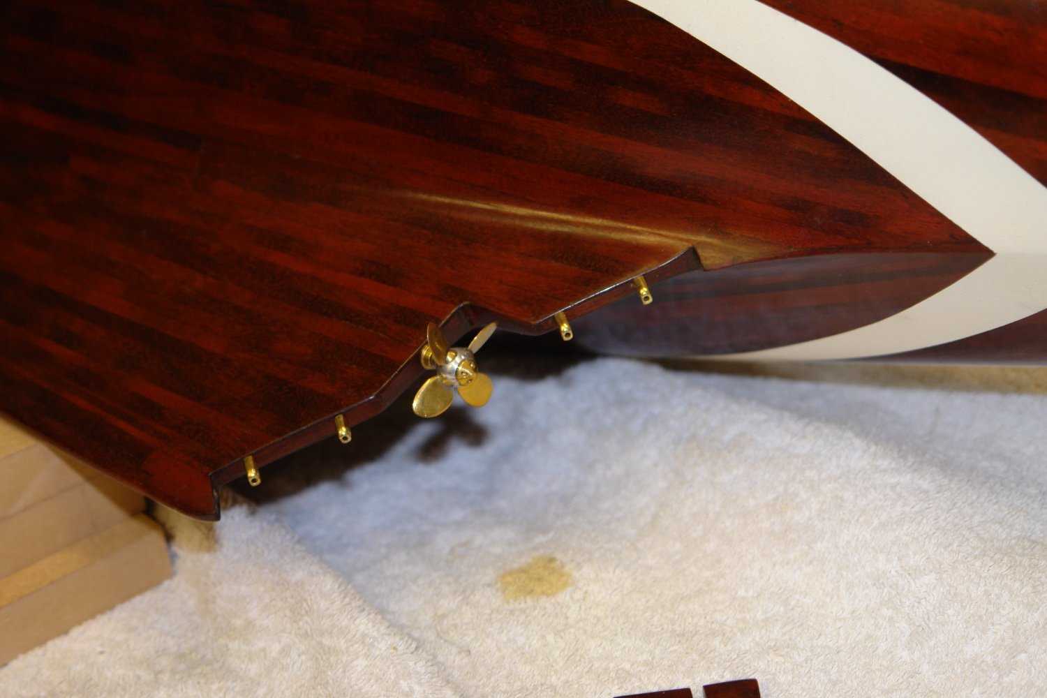
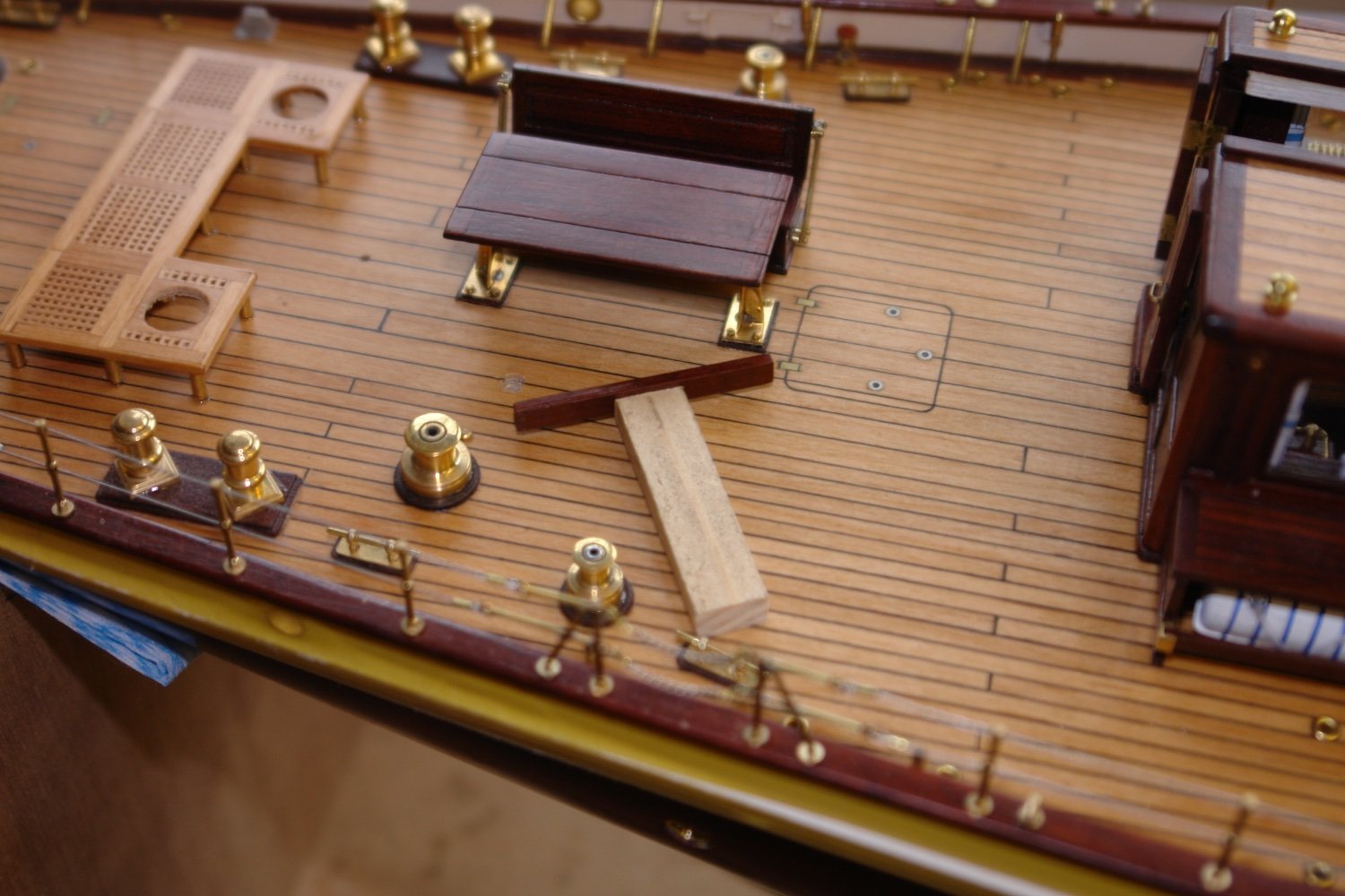
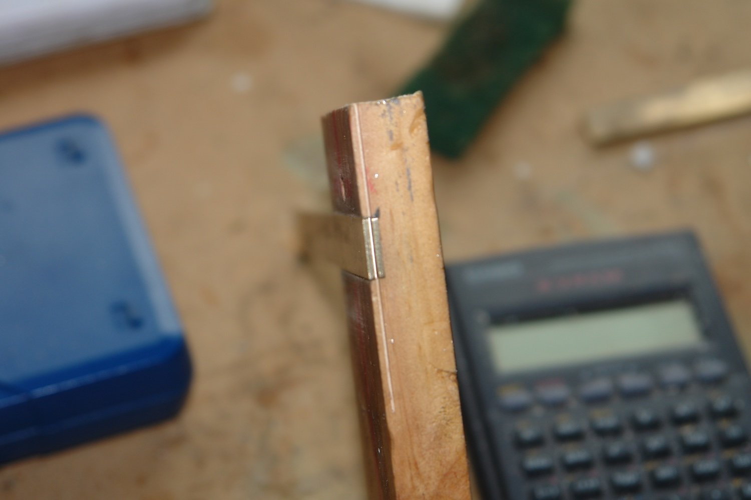
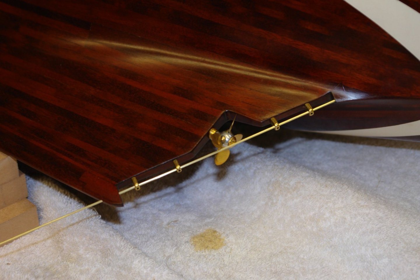
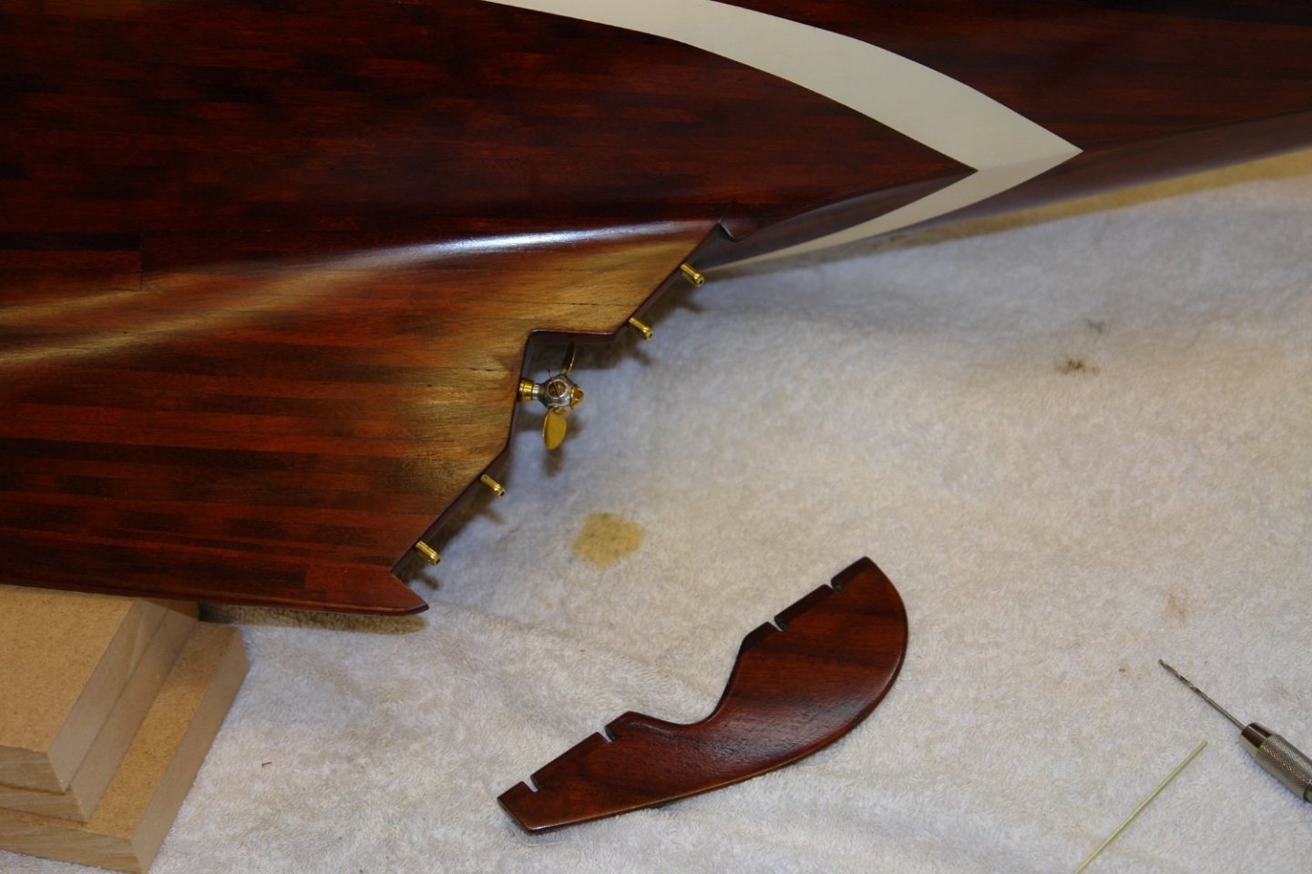
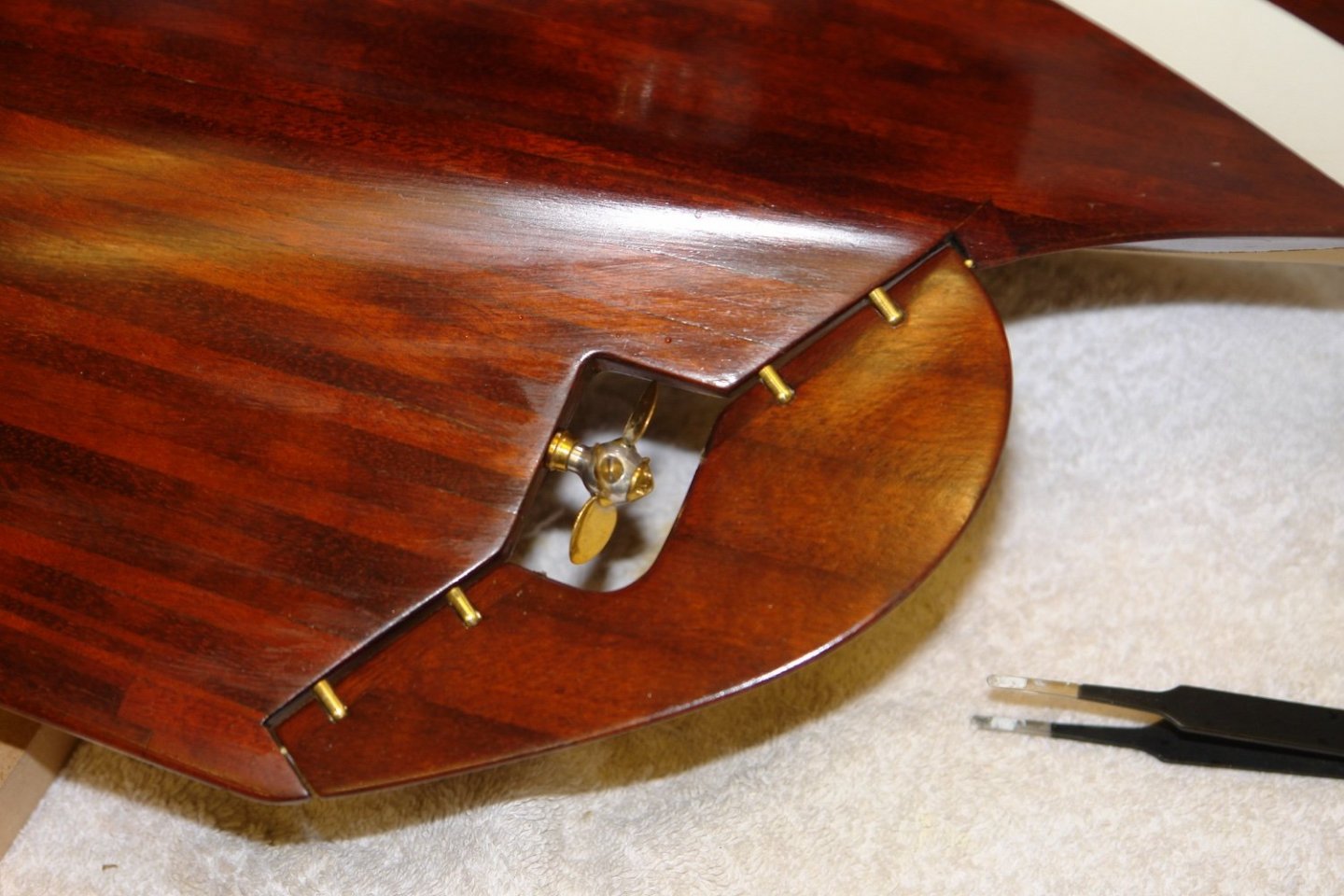
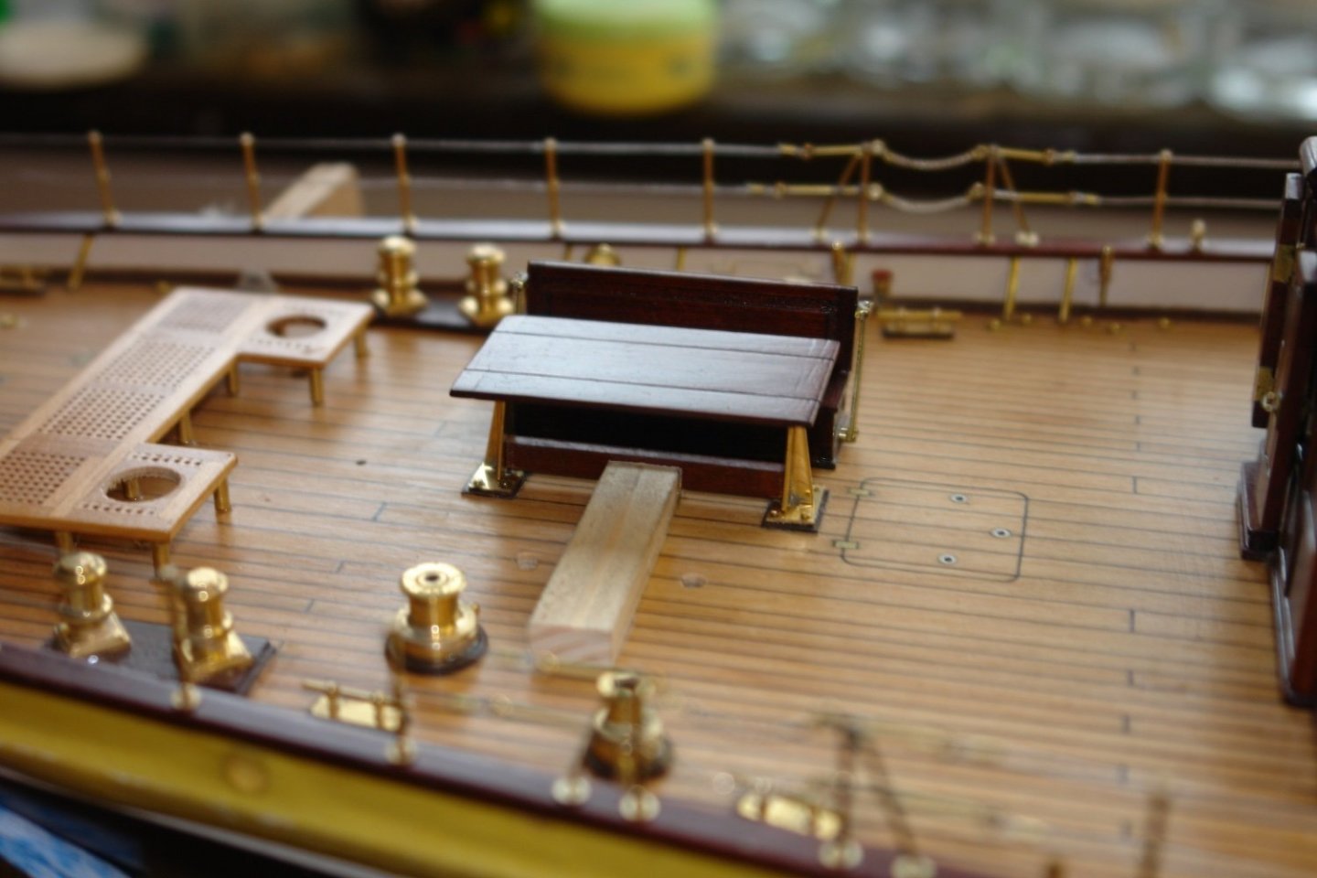
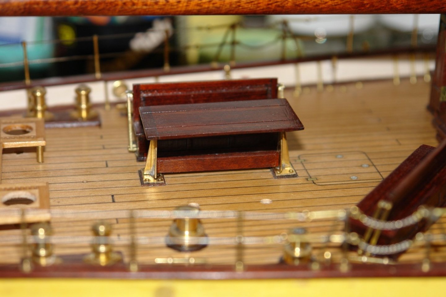
A bit of sorting out loose ends before getting back to the masts and spars. The screw and the rudder have been sat in my bits box for over 2 years and now seemed to be an appropriate time to fit them. The bore for the screw had been pre drilled and it was a simple case of insertion and gluing in place. Holes for the hinge mounting spigots had also been predrilled and these were inserted and glued in position. The rudder shaft was a piece of 1/16" brass rod. Fortunately, by either luck or judgement, it slid into place without interfering with the screw. As can be seen the shaft locates in the 4 hinges and a hole in the hull and keel. Satisfyingly the alignment was spot on. To mount the rudder the shaft needed to be in 2 pieces ( a gap being required at the screw cut out). The upper shaft had to be inserted through the lower part of the rudder. Some time back one of you pointed out that I had omitted the cross brace below the on deck dining table. Quite a serious omission as its main use is to brace the crew who are sitting and drinking gin while close hauled. I had looked at retrofitting it some time ago but getting it located and glued in place had proved somewhat fiddly, so I left it for later. Today was "later". After some head scratching i decided to fix the brace to the end of a piece of scrap wood with double sided tape. The correct height been set with a couple of shims. With this set up the brace was moved into position and glued with CA. Once the glue was dry the scrap wood was eased away breaking the double sided tape bond. The crew can now drink their gin in comfort in the knowledge that they are no longer rudderless.


-
Yes Micheal. I am still working my ay through a 1930's mahogany dining table, picked up for a song at the local auctioneers. "Brown" furniture is really out of fashion here and much of it ends up in the skip. Cutting up a quality table seems a crime but at least I rescued it from oblivion. Old mahogany is vastly better than the modern stuff. Thank you to everyone for your continuing support and comments.
-
Beautifully neat and clean build.
-
Eberhard, beautiful job - the spacing on the bars looks excellent. I tried to look up what vintage LRZ 602 was but failed.
-
Yes it is fun finding ways of making things, well done thus far.
-
HMCSS Victoria 1855 by BANYAN - 1:72
KeithAug replied to BANYAN's topic in - Build logs for subjects built 1851 - 1900
Hi Pat, Is the shipyard experiencing an extended shutdown? Looking forward to the next instalment.- 1,021 replies
-
- 3
-

-
- gun dispatch vessel
- victoria
- (and 2 more)
-
Good to see the sawdust phase has started.
-
I don't know how it is possible to make such quick progress. Do you ever sleep?
- 454 replies
-
- 2
-
-

-
- Union Steamship Company
- Stepcraft 840
- (and 3 more)
-
Keith - I finished my machine training when I was 17 and although i worked in engineering roles throughout my career I was never required to cut metal again in anger throughout my working life. I only started machining again when I retired. It's amazing what you remember over the period of 43 years (between the age of 17 and 60).
-
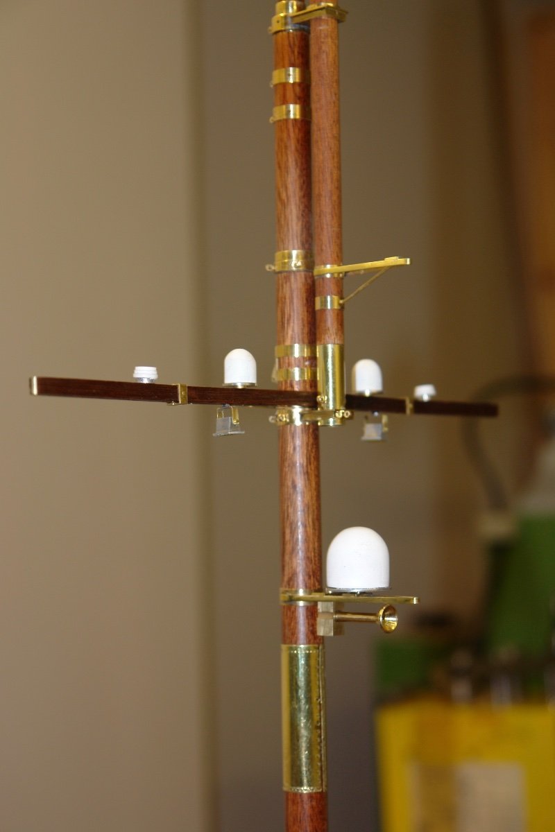
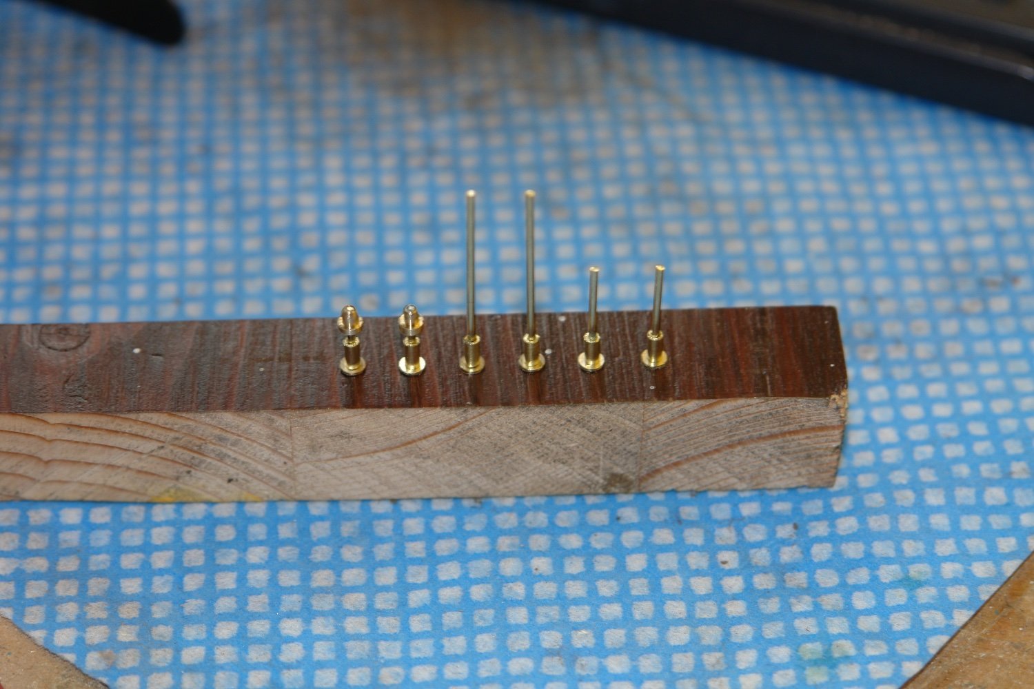
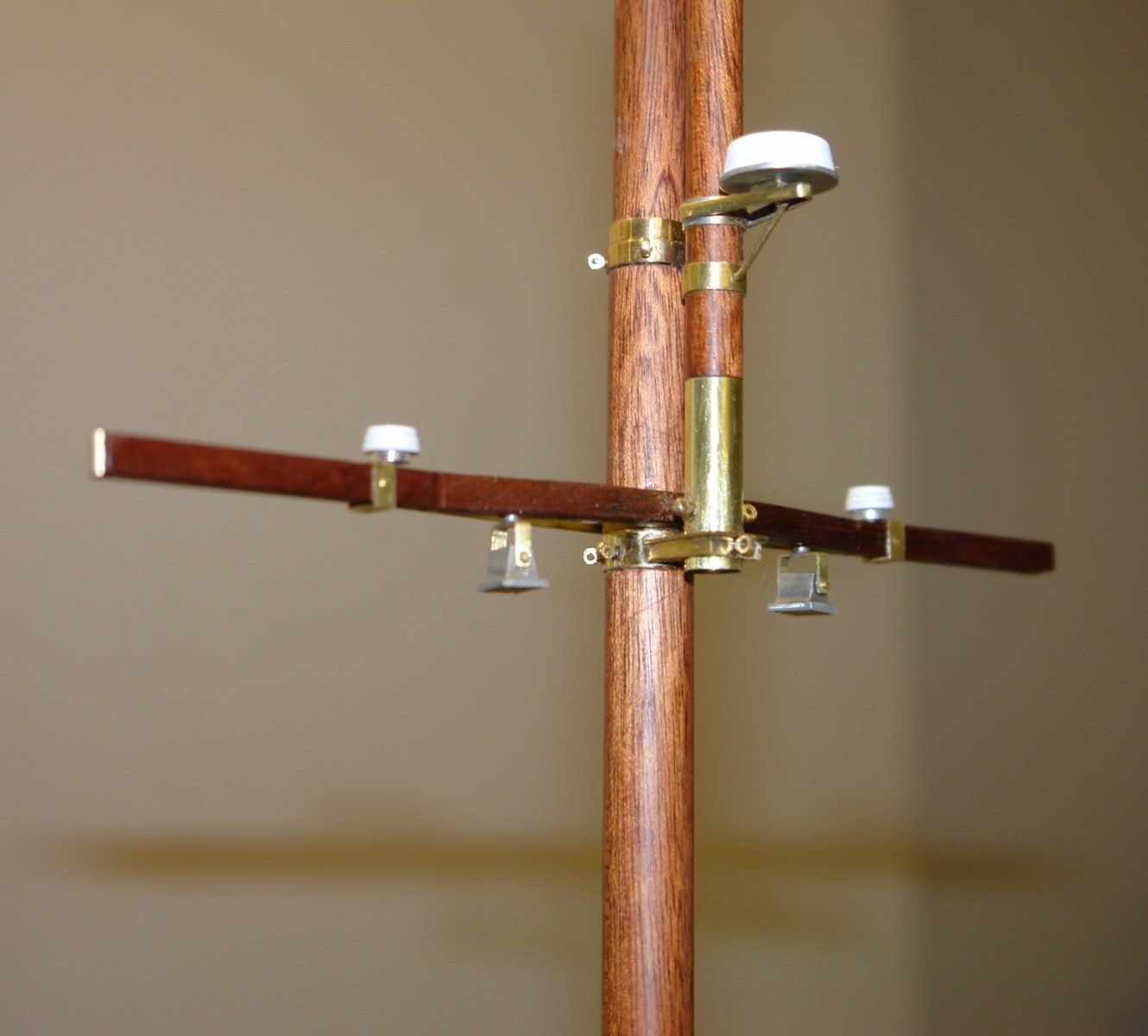
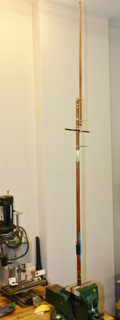
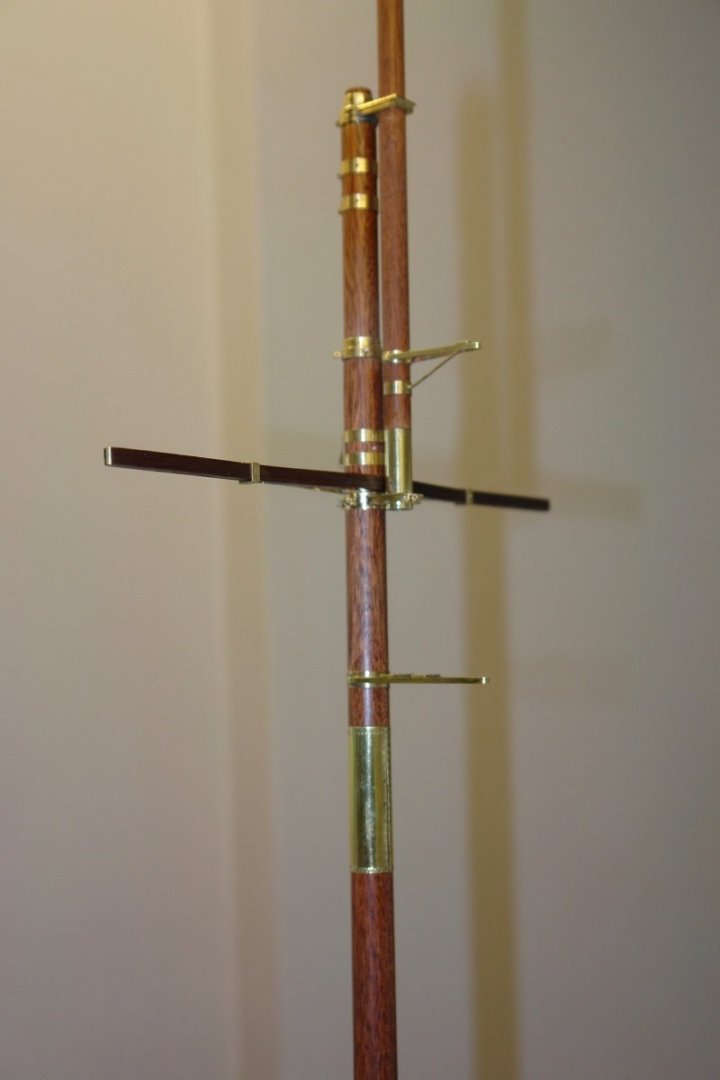
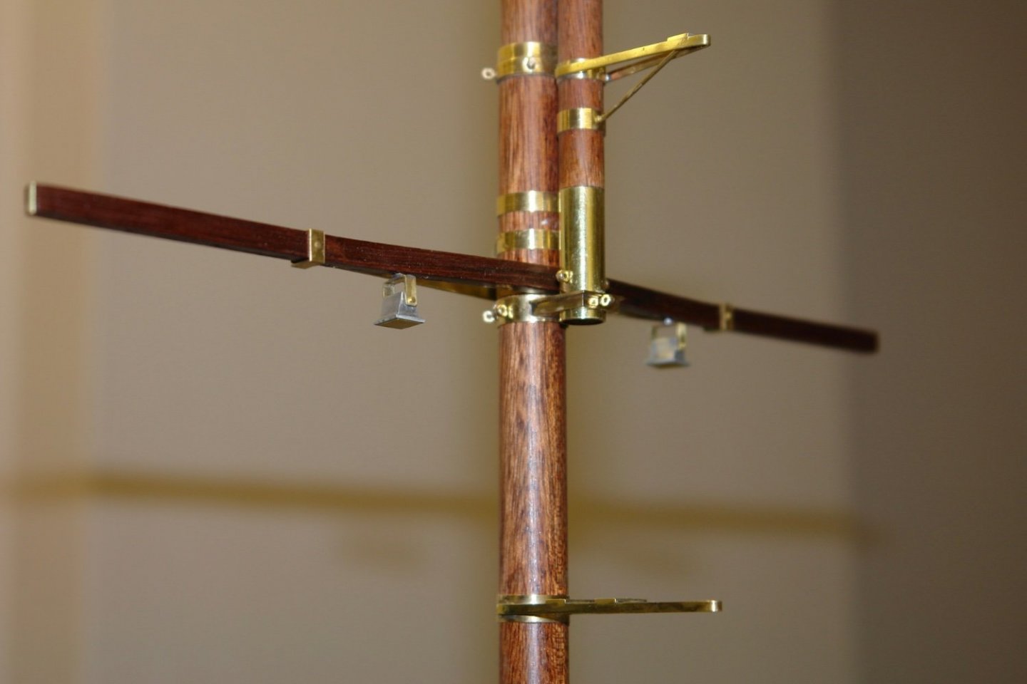
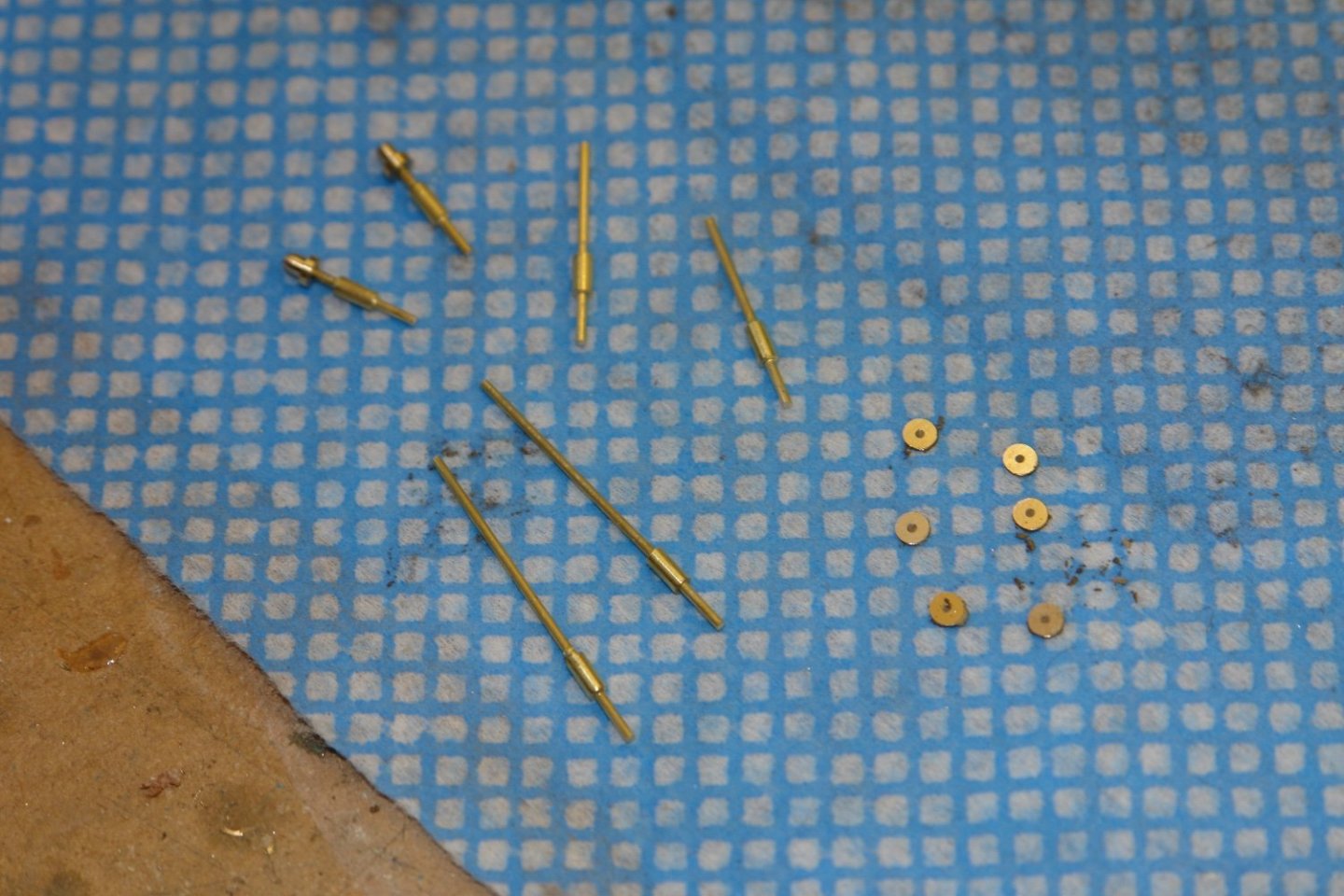
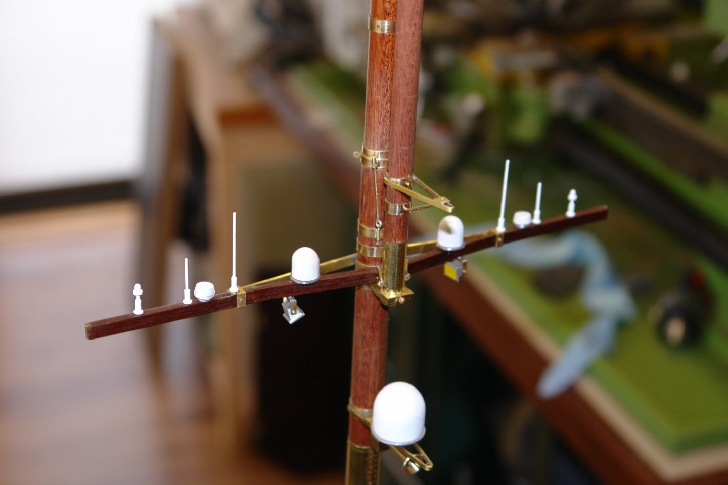
Thank you all for your kind comments. I'm not sure they were very interested in my boat building skills Keith. Today I did a bit of assembly - feels more like progress than many tasks. I thought I would start with a photo of the main mast taken several weeks ago - just to give some idea of scale. I think I am going to need to start a negotiation with my better half on Germania's final display location. The main mast cross trees started out little bare. But soon acquired a pair of deck flood lights. Then the various electronic appendages started to appear together with the ships horn. I needed 6 aerials - made from wire and bar - a simple bit of turning. A quick coat of paint and they were then glued into holes previously drilled in the cross trees. I also added the cables which support the top mast. I left the radar off for the time being. I then move to the foremast - which was somewhat simpler.


-
Interesting process for making the blocks, they turned out very well. What are the dimensions for the 3 sizes please?
- 153 replies
-
- 2
-
-
- Ancre
- Bruno Orsel
- (and 2 more)
-
interesting vessel and nicely built. It would be nice to see a build log for your next boat Welcome aboard.
-
Some time ago a post prompted a degree of speculation about some electrical boxes at the base of the main and fore masts. The speculation prompted their inclusion.

-
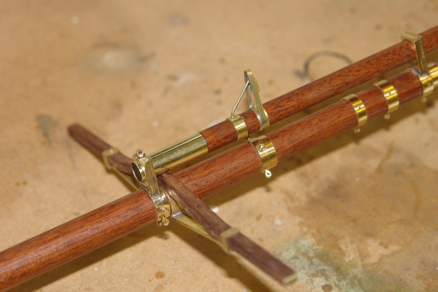
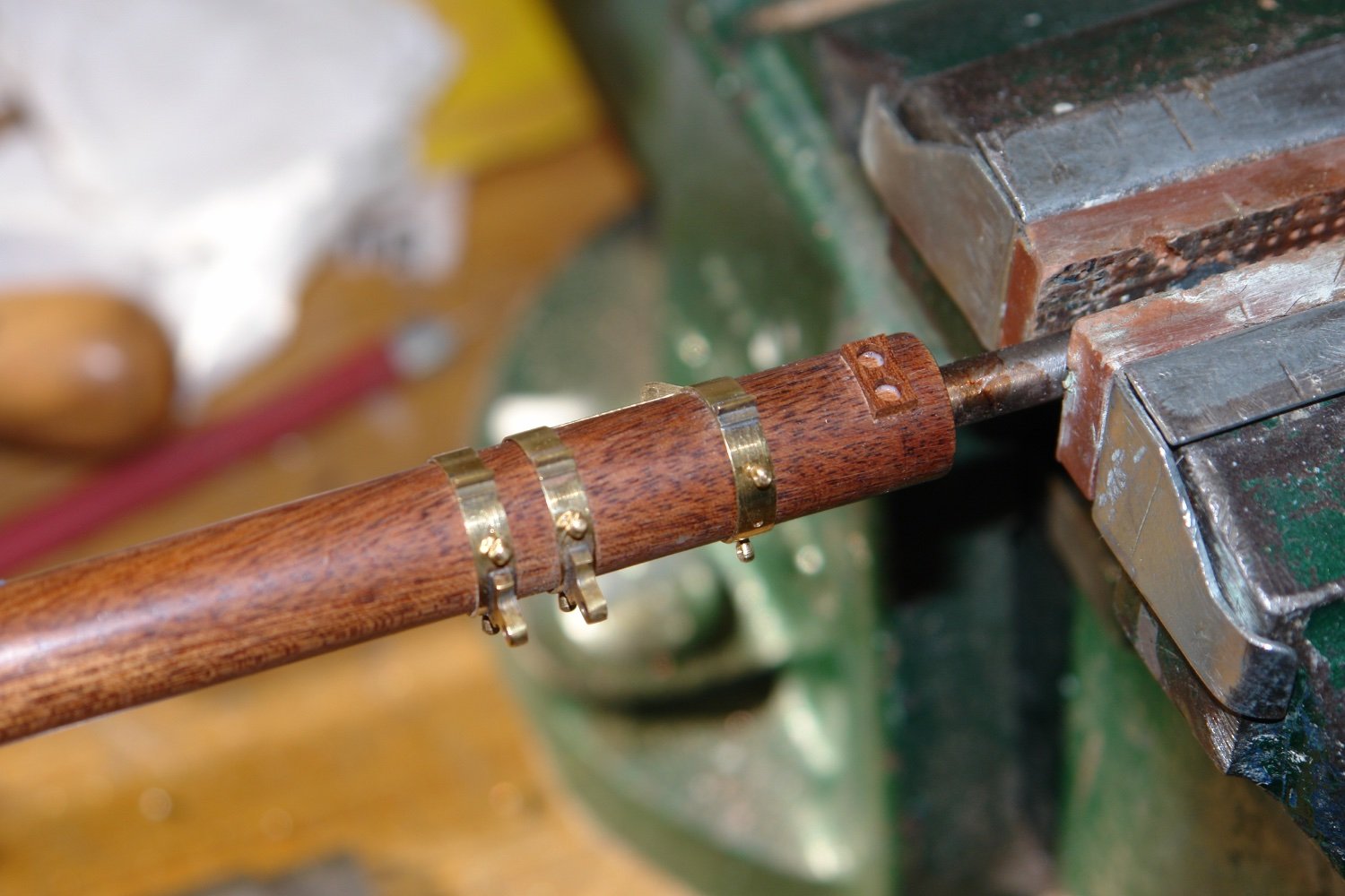
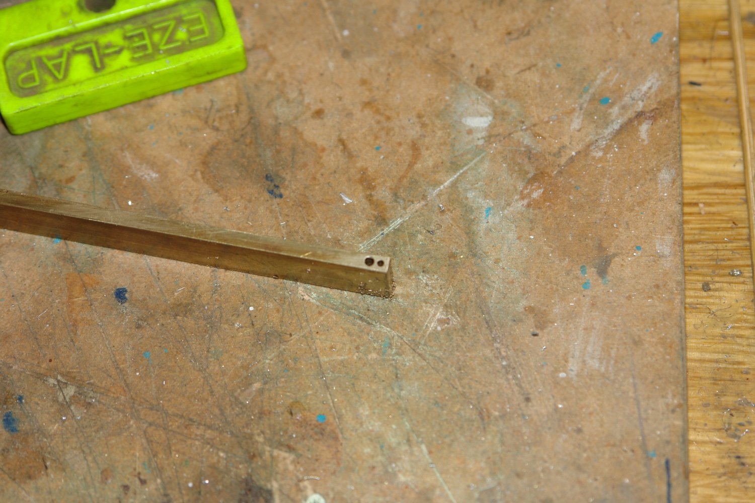
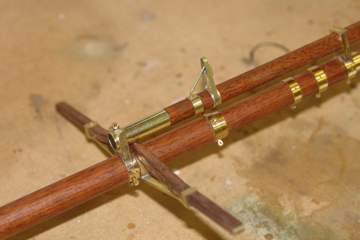
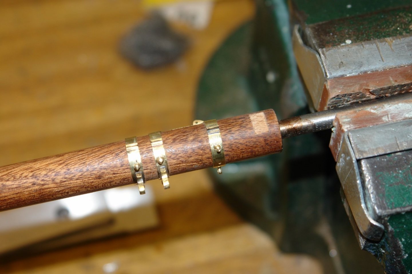
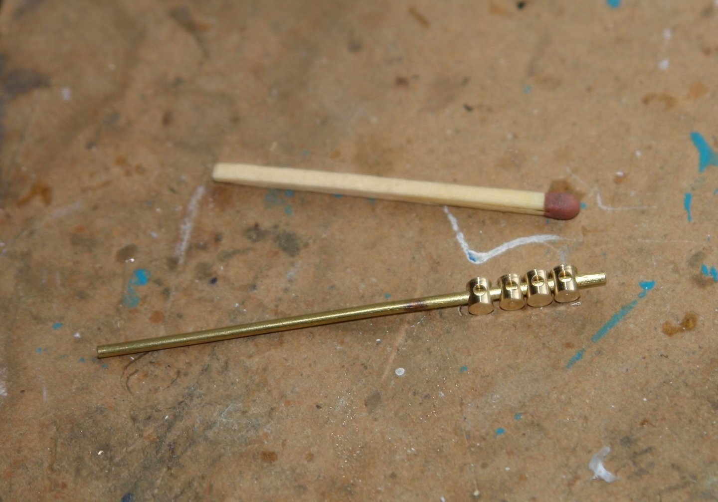
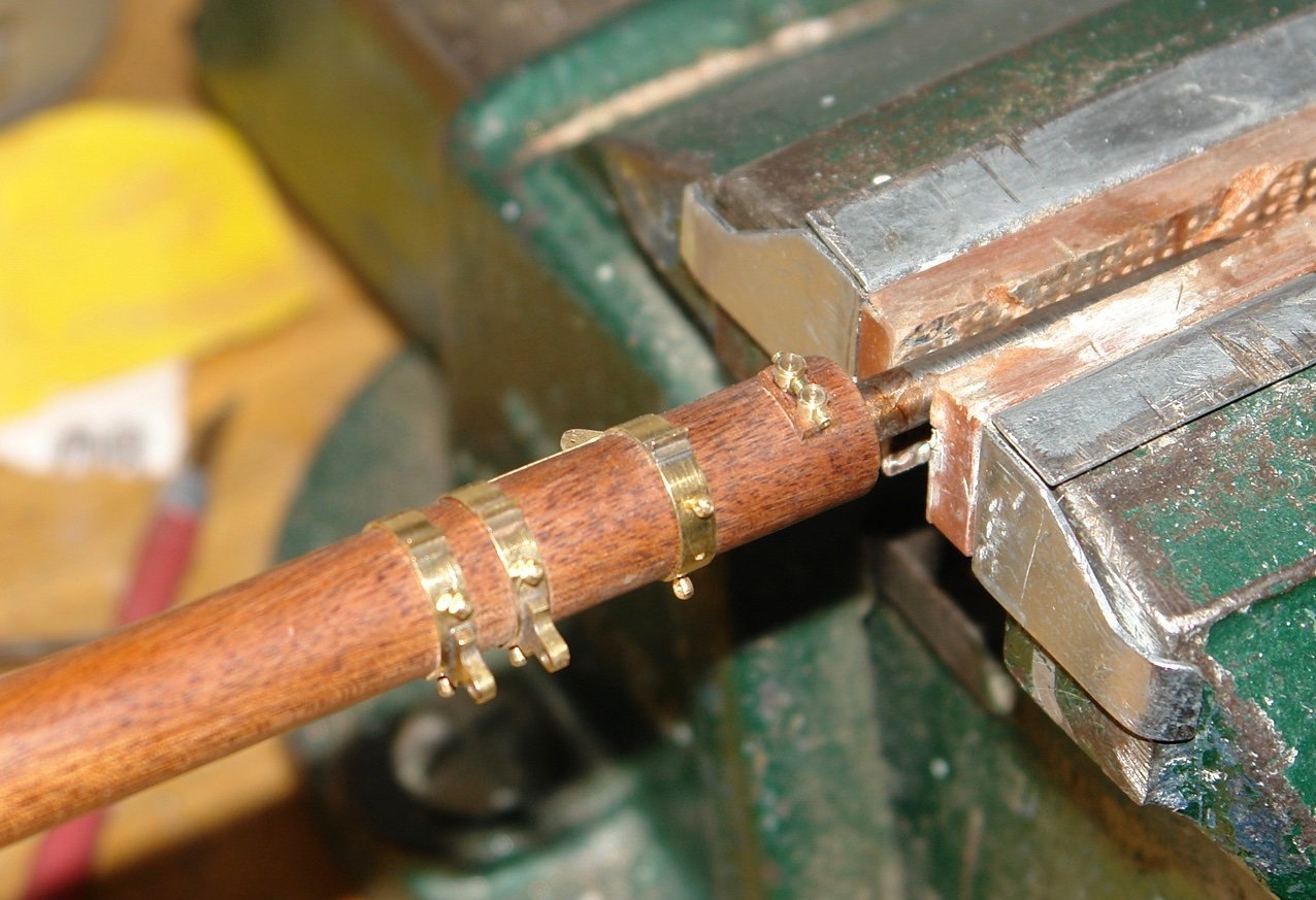
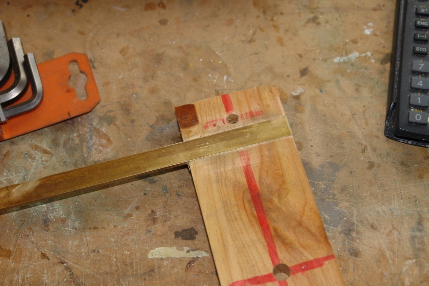
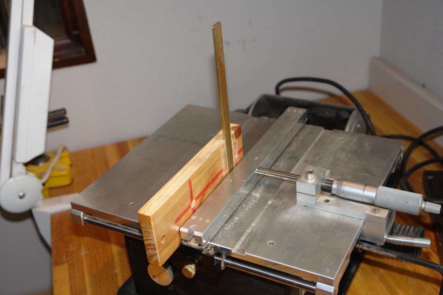
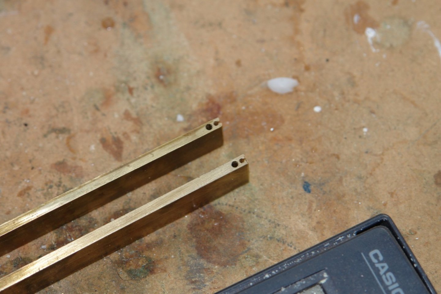
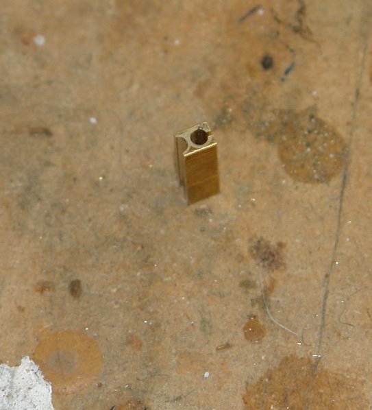
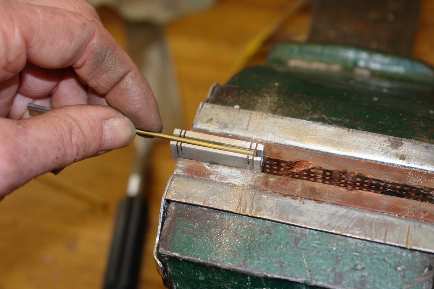
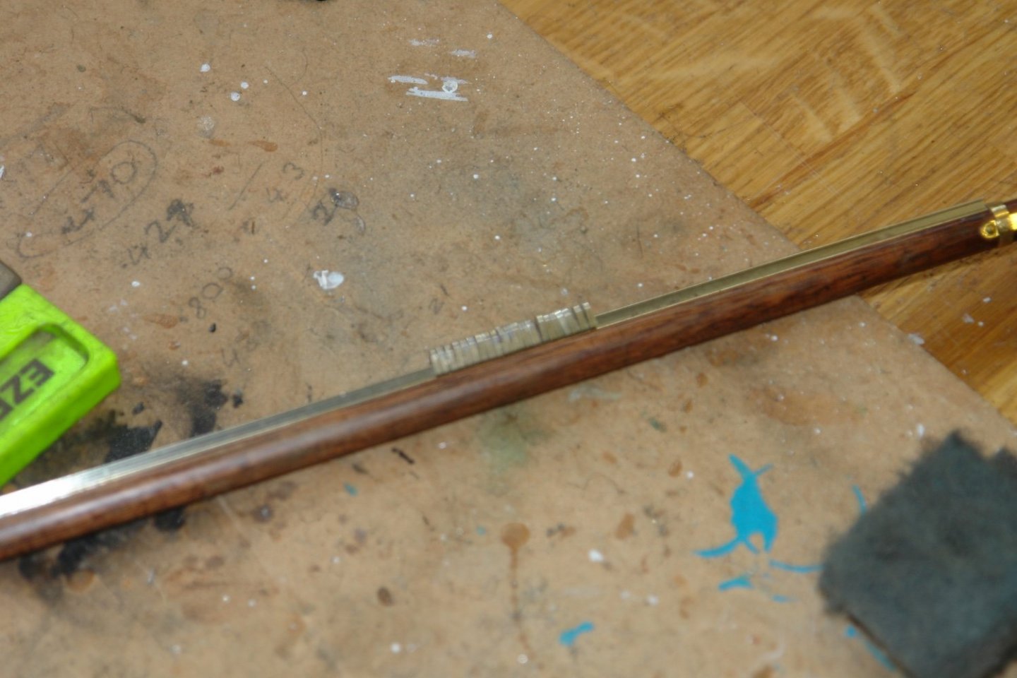
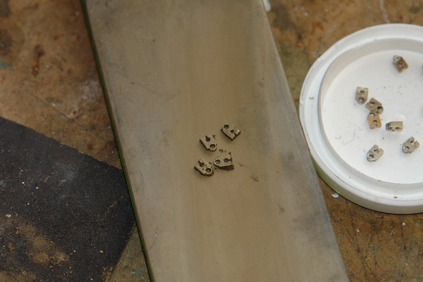
thank you Steve, Keith, Pat and Micheal. I decided to make the boom track and runners next. I didn't have a lot of detail of the sliders and because of the number (circa 70) I decided to repeat what I did on my Altair build. The track was the rail from OO gauge model railway. The booms were slotted on the mill to take the base of the track and the track was glad in place with CA. The runners were machined from a 1/8" x .5" brass bar. This was first drilled with 2 holes, the larger being 3/32" and the smaller bine 1/16" A .040" slot was cut into the smaller hole using the table saw. I made a jig to hold the brass bar for the slotting operation. The ends were then cut off on the centre line of the larger hole. Then a 3/32 brass tube was soldered in the semi-circular hole. Another small jig was made to aid accurate slicing off of the runners. With that little exercise complete it was back to more mast and boom work. I think I am going to short circuit some of the detail and only focus on the major bits.


-
Amazing detail Patrick. Glad to see you back. Happy new year.
-
Is that a Port bottle cork? Suddenly working in miniature is becoming a lot more appealing.
-
Valeriy / John - excellent - i had worried that this was a lost resource.
-
Cap San Diego by mikegr - 1/160
KeithAug replied to mikegr's topic in - Build logs for subjects built 1901 - Present Day
I hope the fibreglass works. A 3rd start is too soul destroying to contemplate.