KeithAug
-
Posts
3,986 -
Joined
-
Last visited
Content Type
Profiles
Forums
Gallery
Events
Everything posted by KeithAug
-
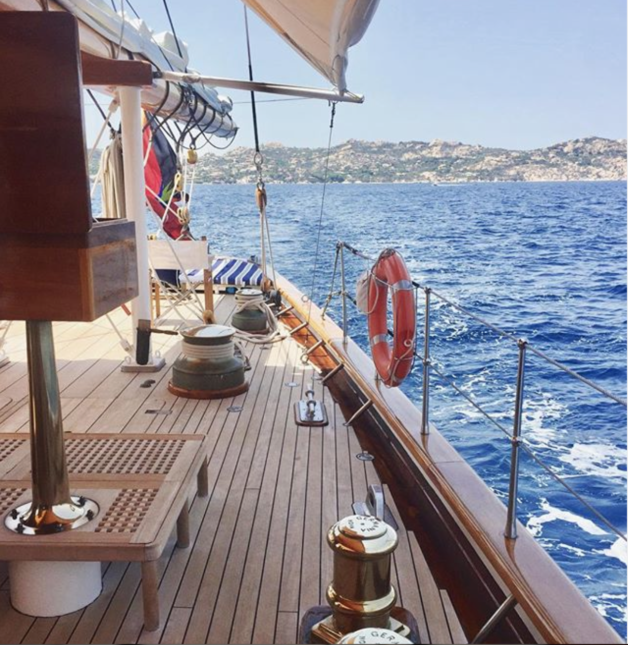
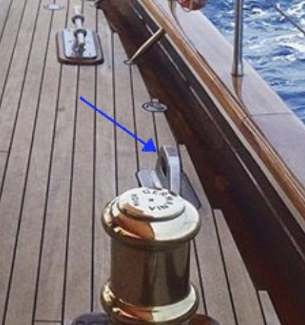
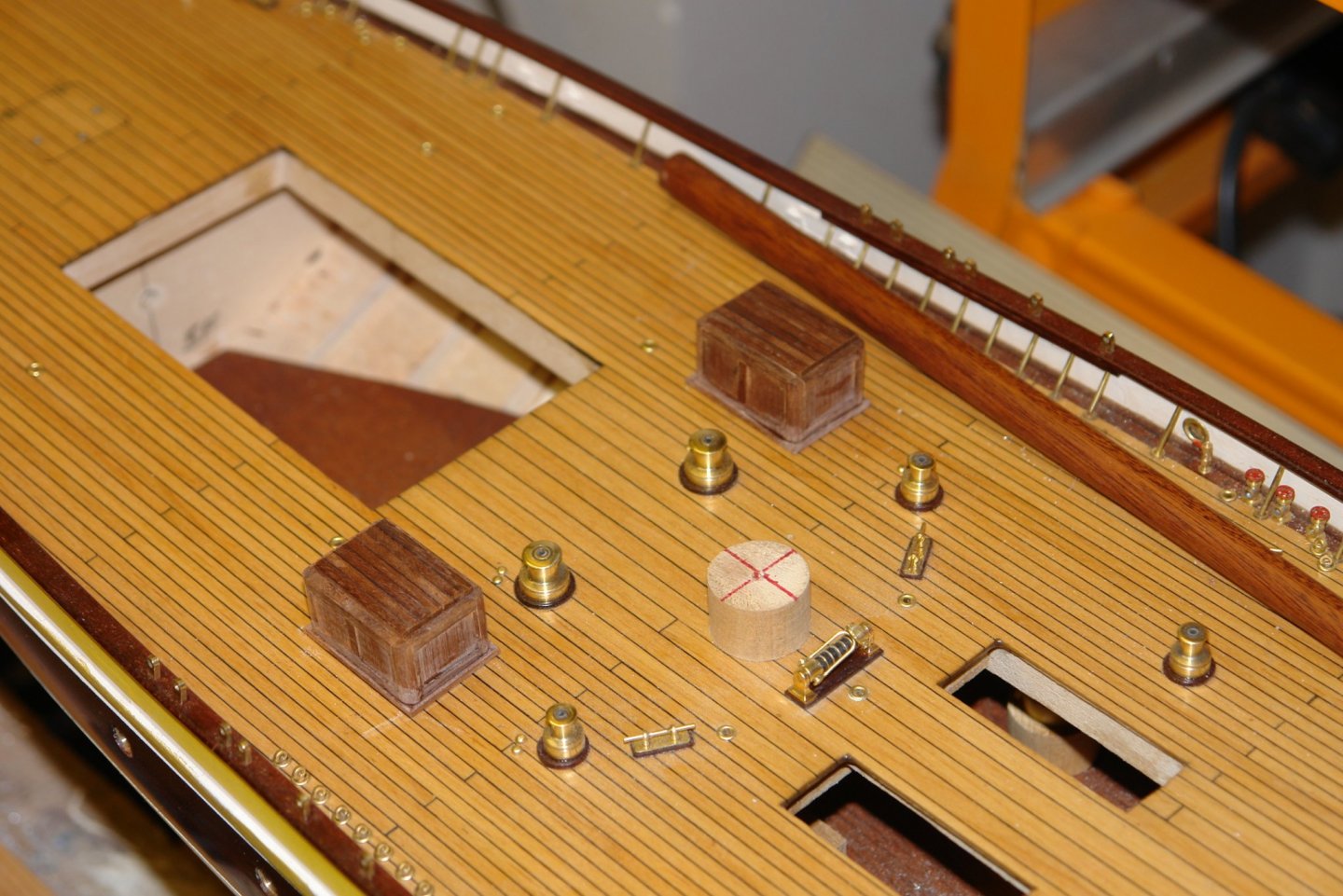
 Innisfree - thank you for your interest and comments. The bracket is actually symetrical but other than that your suggestion is as valid as any. The fact that a couple of very hefty bollards are attached to the deck a couple of feet away makes its use as a towing feature somewhat unnecessary. You can see one of the bollards to the right of the bracket.
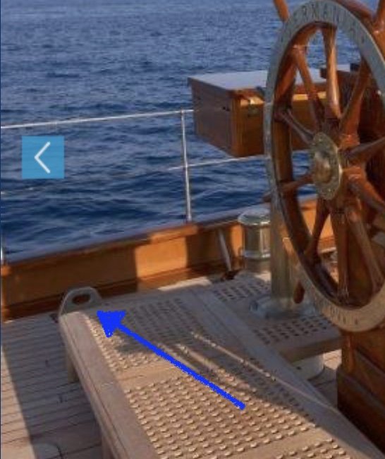
-
Keith, not really in the right position for fairleads. None of the photos I have ever show them in use.
-
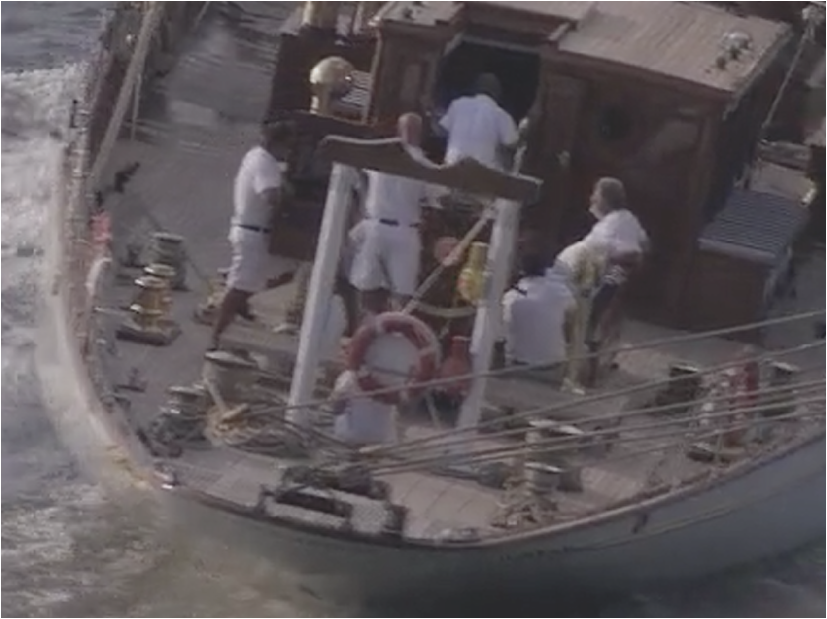
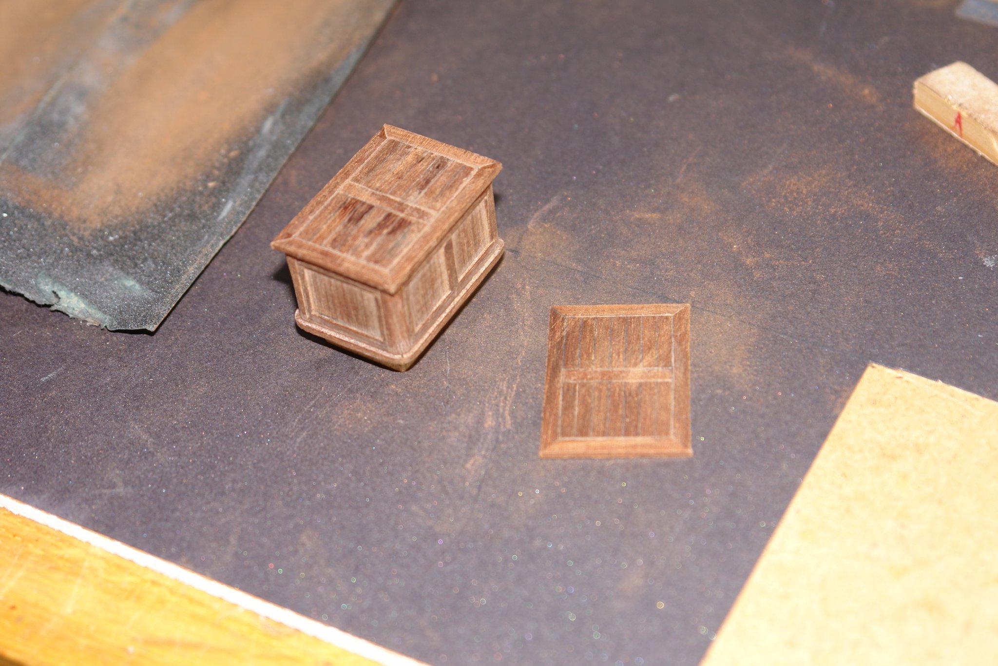
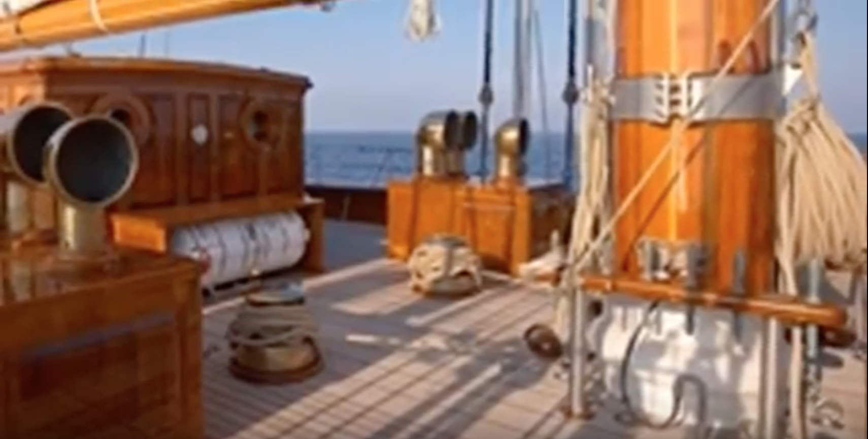
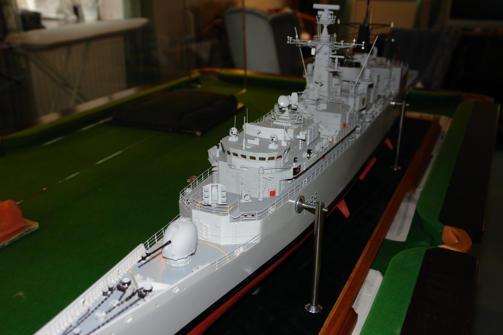
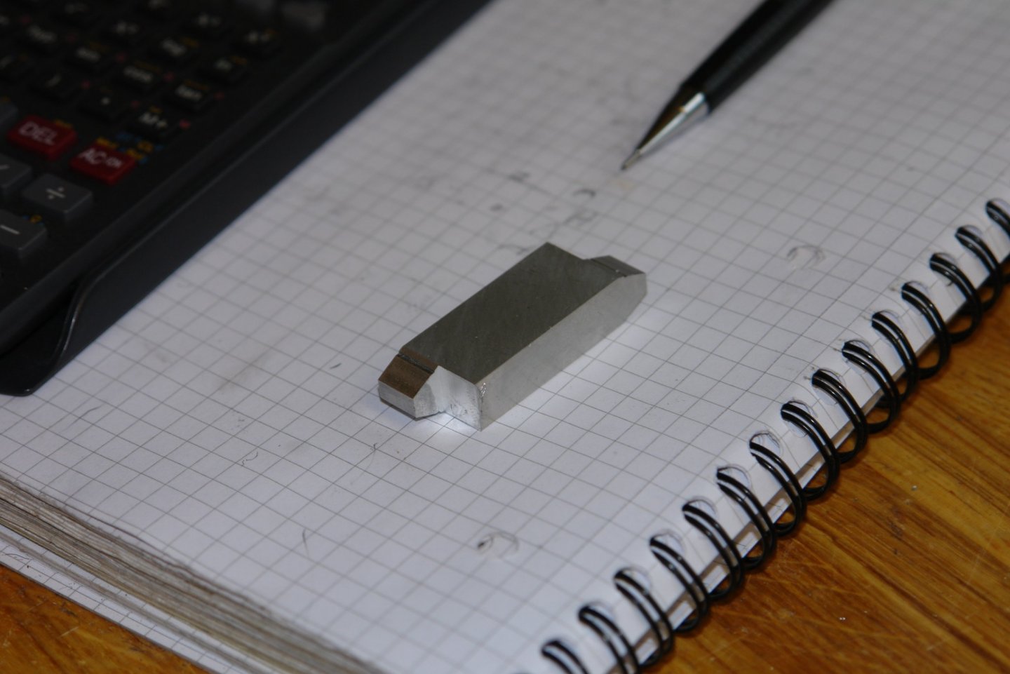
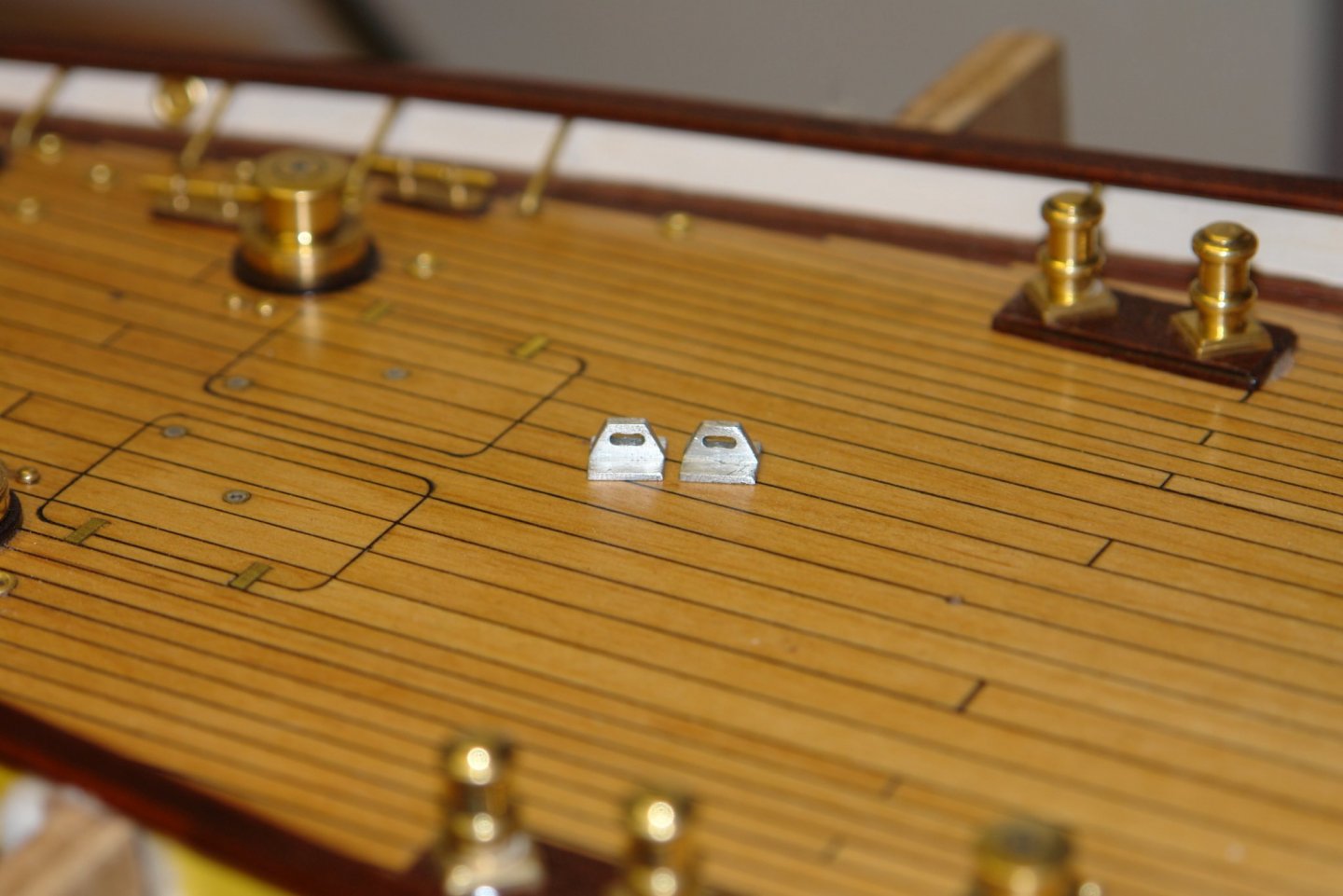
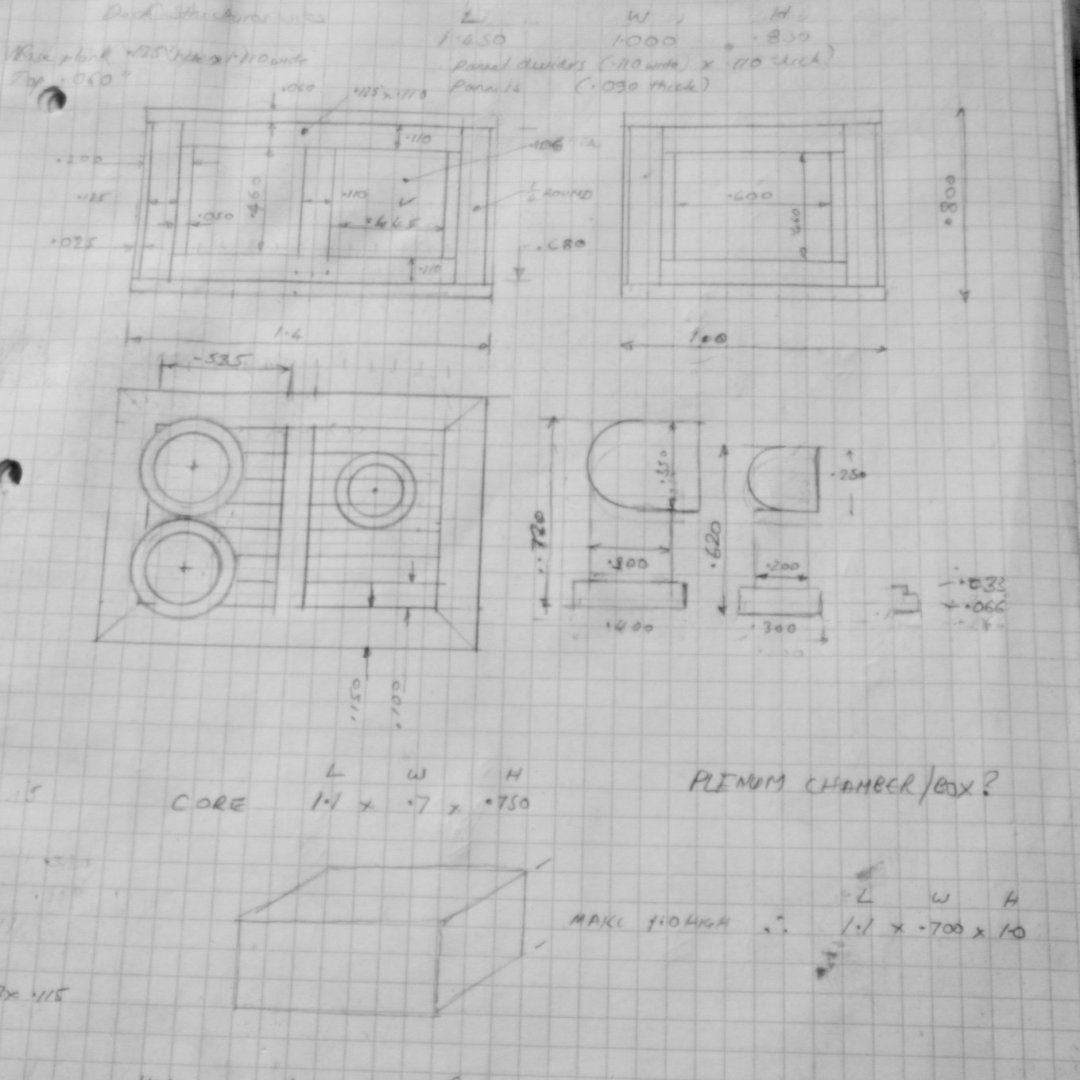
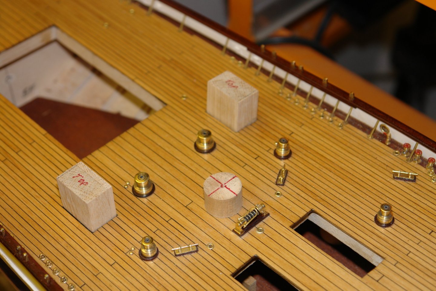
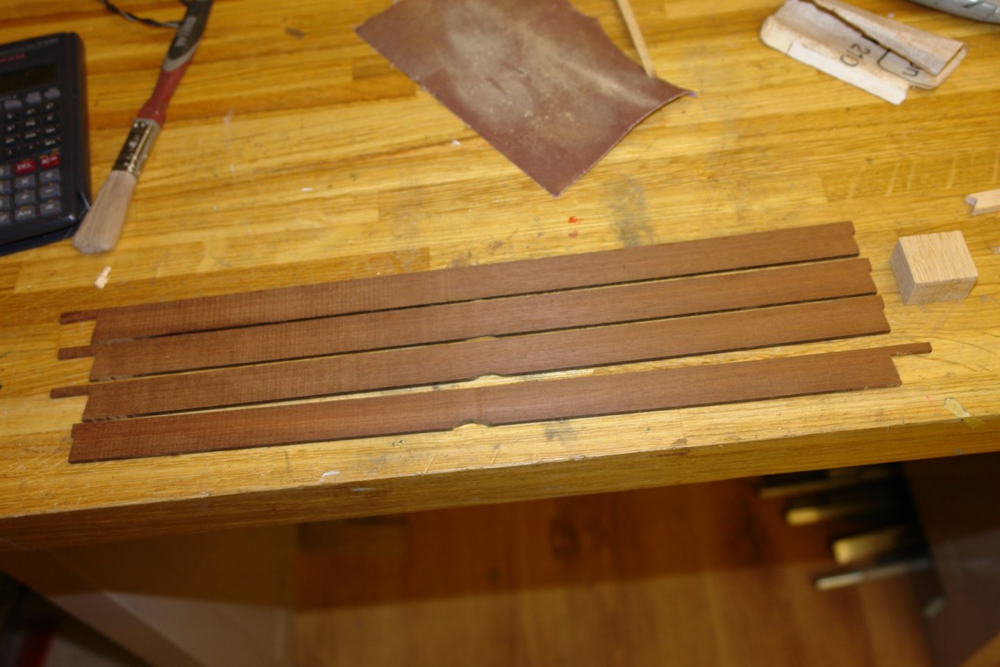
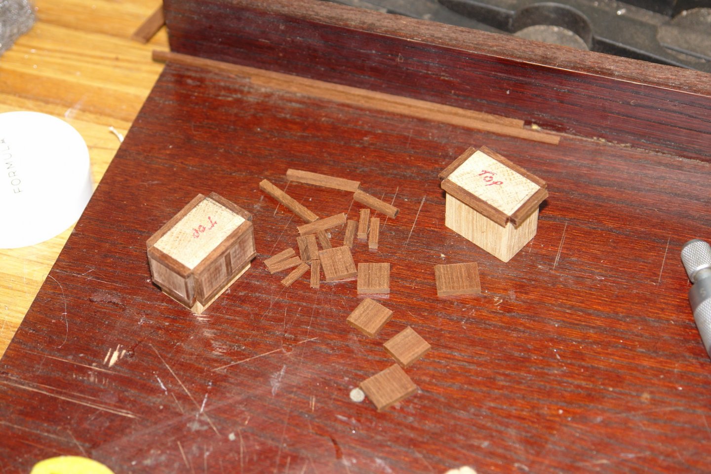
I am minded to think that we have one of the most appropriate pastimes to deal with current world events. I hope you are all keeping safe in these strange times. I made less progress than expected over the past few days. Two oddly shaped brackets are positioned on the aft deck. I am really not sure what they are for or why they are the shape they are. They were made from a scrap of aluminium - one bracket cut on each end. The base is .3" square and the web is .175" high Just forward of the main deck house are couple of boxes each with 3 vents. As usual I started with a sketch, the overall size is 1.4" long by 1.0" wide and 0.8" high. The boxes were built around oak block cores. The cladding was made out of mahogany ripped down to the 3 required thicknesses of 0.1" 0.125" and 0.150". The cladding process is fairly simple and not worthy of much explanation. The top surface is planked with caulking between the planks. The planks are 0.1" wide by .060" thick. The next post should be more interesting as I get onto more complicated deck houses. Keep safe.


-
Beautifully done Richard. I must get me some boxwood.
-
Eberhard - The room size is the table dimensions plus 5 foot cue length all round - so room size is 14' x 18' this and the fact that it weighs about a ton is the reason no one wants it. My wife says If I get rid of it I can move the workshop in but I think this is a ruse. Unfortunately Mr Trump has banned me from visiting for the foreseeable future. We were planning to visit my brother-in-law in Arizona - perhaps next year. Thank you John, nice to hear form you. Richard - I also have a load of granite worktops out back - recovered from the previous kitchen, you are welcome to them - but again Mr Trump probably wont allow.
-
Keith - The playing surface is 8x4. It is quite a good table - solid one piece slate bed on a mahogany table. I really don't want to smash it up to dispose of it but no one wants them anymore. Probably incompatible with modern house room sizes.
-
Very nice work Schooners. I will be interested to see how the building frame is constructed. Beware of face masks - the virus is small enough to pass though the fabric of most masks.
-
Richard, Gary, Roger, Mark, Geert - Thank you all for taking the time to comment. And thank you to everyone for the thumbs up's.
-
I agree - but will shorten them - I don't think acrylic would be strong enough without going to a bigger diameter.
-
Yes Keith - snooker playing days are over, my playing partner (son) got married and had a child. The table is on the disposal list but I can't find anyone who wants it - even for free.
-
Eberhard - yes it was for stability but having tested them out I think I can reduce them by about 2 inches without too much compromise.
-
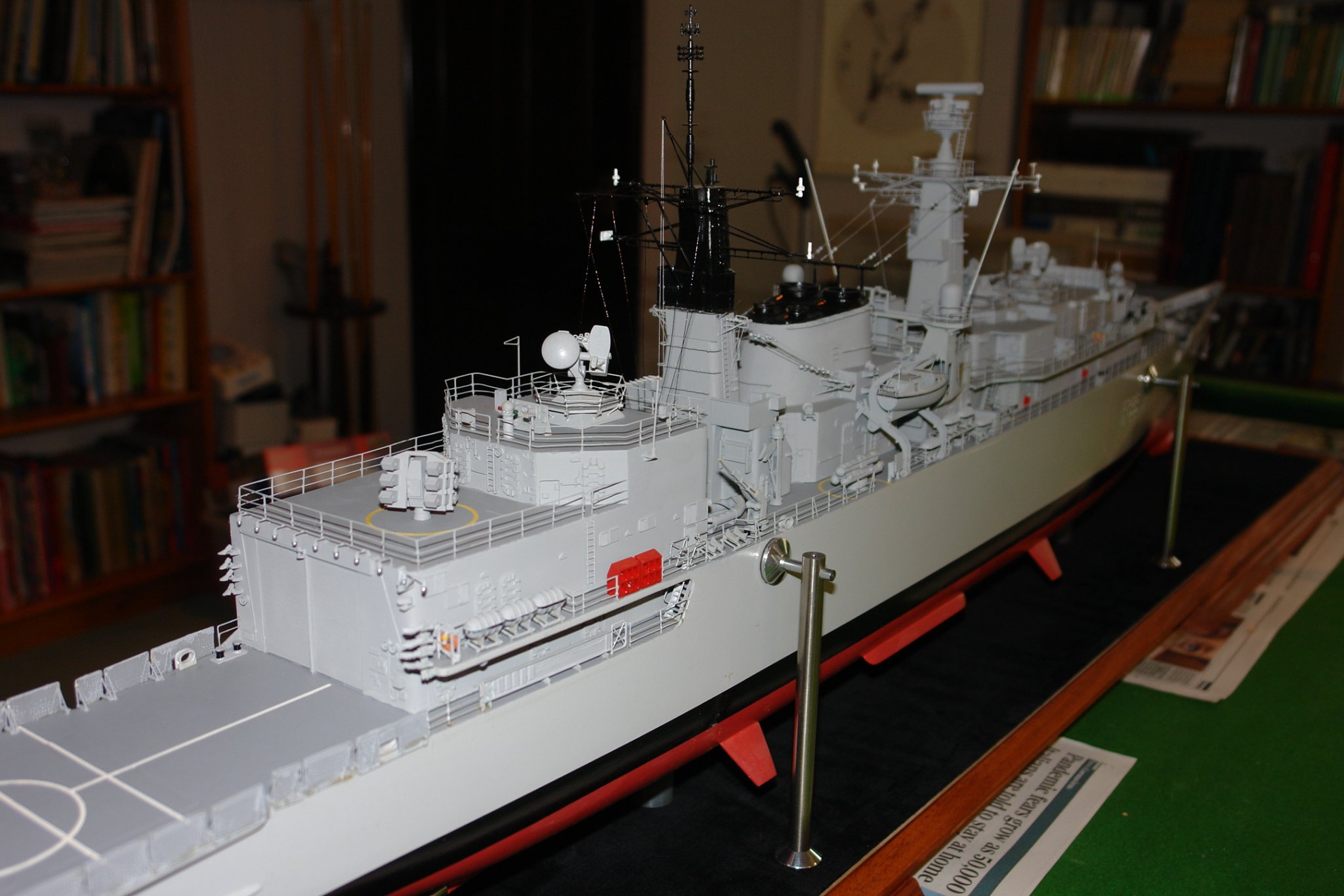
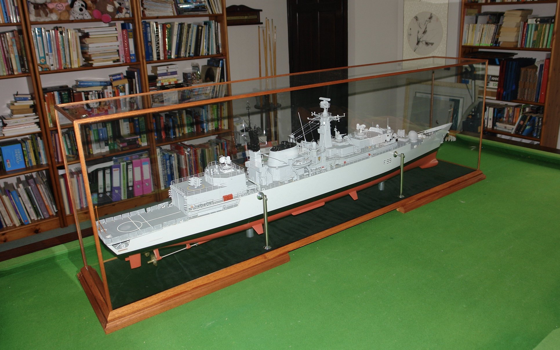
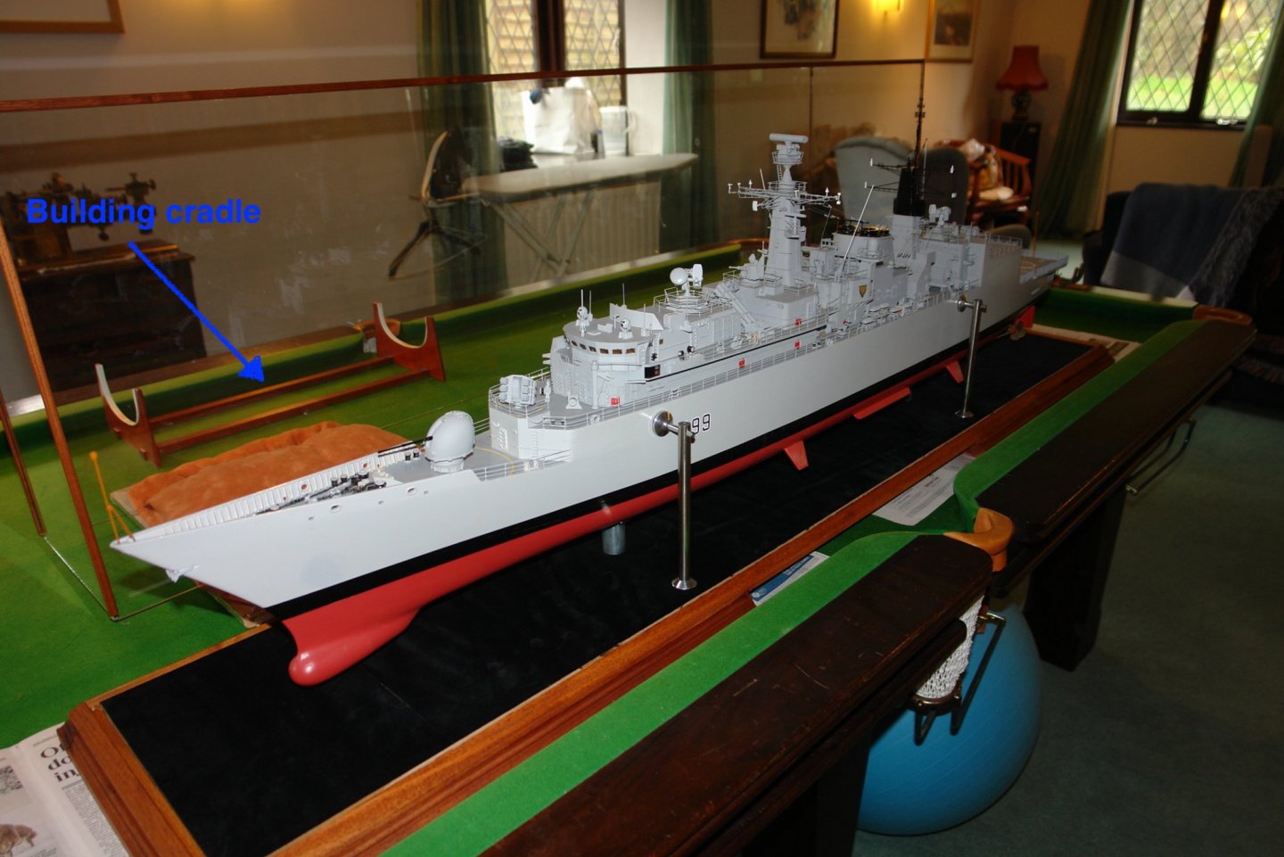
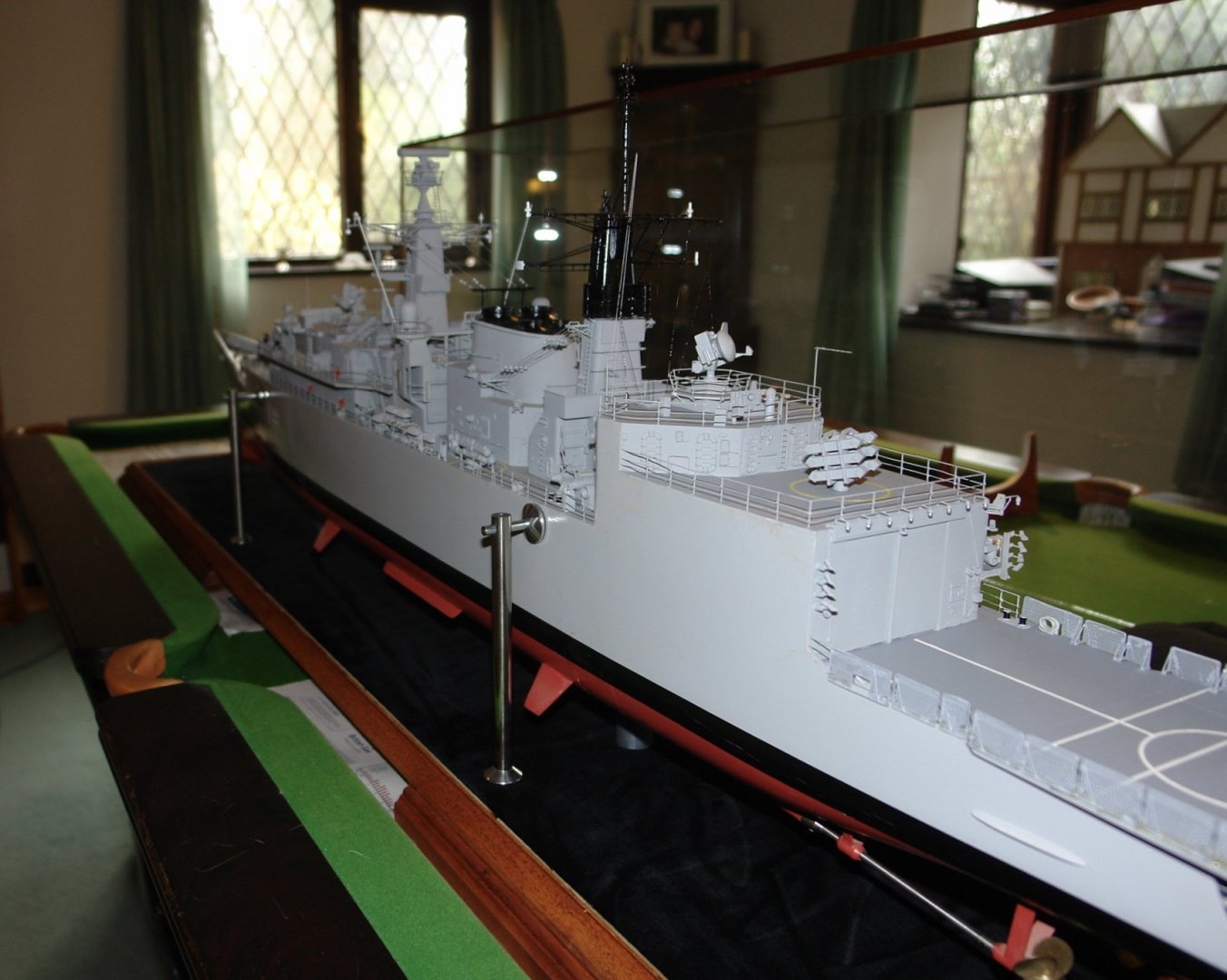
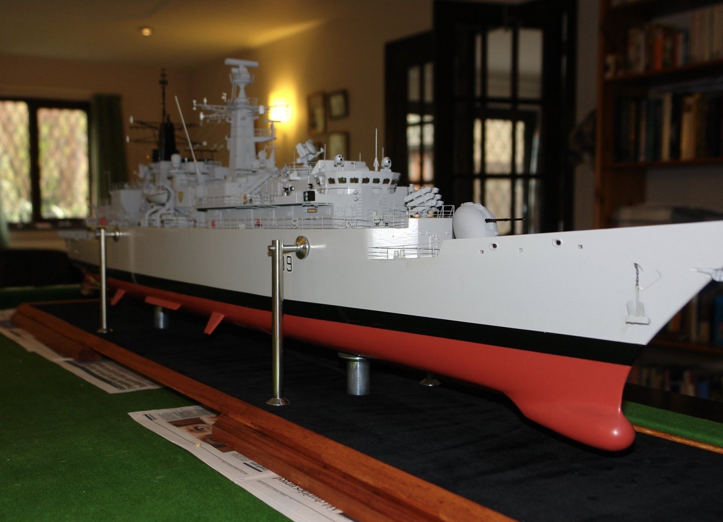
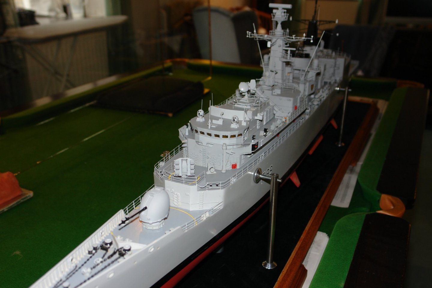
Ok - I apologise for my little game, I blame my incarceration. About 7 years ago I completed HMS Cornwall and since then she has resided in a plastic bag on a top shelf of the workshop, occasionally picking up minor damage. I couldn't be bothered to make a case, or get round to ordering one. Finally the need for workshop shelf space prompted me to buy one and fortunately it was delivered the day before lockdown. Rather than install the model on a stand inside the case, I decided to engineer the stand into the base itself - hence the metalwork. Well done Eberhard - you win the prize. Oh! and of course Steve you too!!!!


-
Yes Javier - we all seem to be in prison, but at least here the criminals are getting early release. Funny world at the moment.
-
Bad time to contemplate finishing Vaddoc, but I suppose you can just get on with other projects. She continues to look really smart.
-
Another little gem Javier - but how do you make them so quickly?
-
HMCSS Victoria 1855 by BANYAN - 1:72
KeithAug replied to BANYAN's topic in - Build logs for subjects built 1851 - 1900
Just catching up Pat. Some nice details and interesting manufacturing methods - well done.- 1,021 replies
-
- 4
-

-
- gun dispatch vessel
- victoria
- (and 2 more)
-
Eberhard, Keith, Mark, Eric. I really should have explained that while it is relevant to this site it isn't for use on Germania. I think Steve must have made this assumption which is why he found it easy to work out.
-
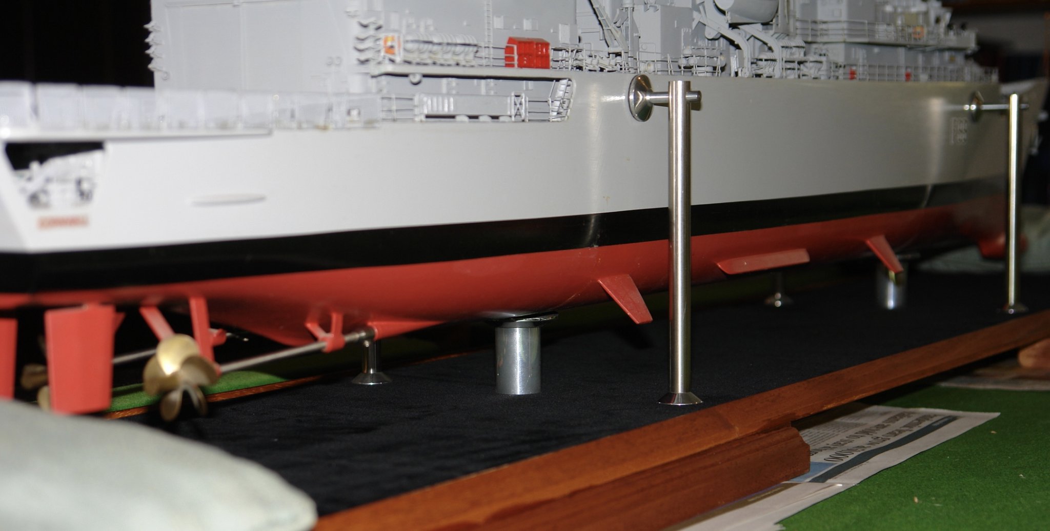
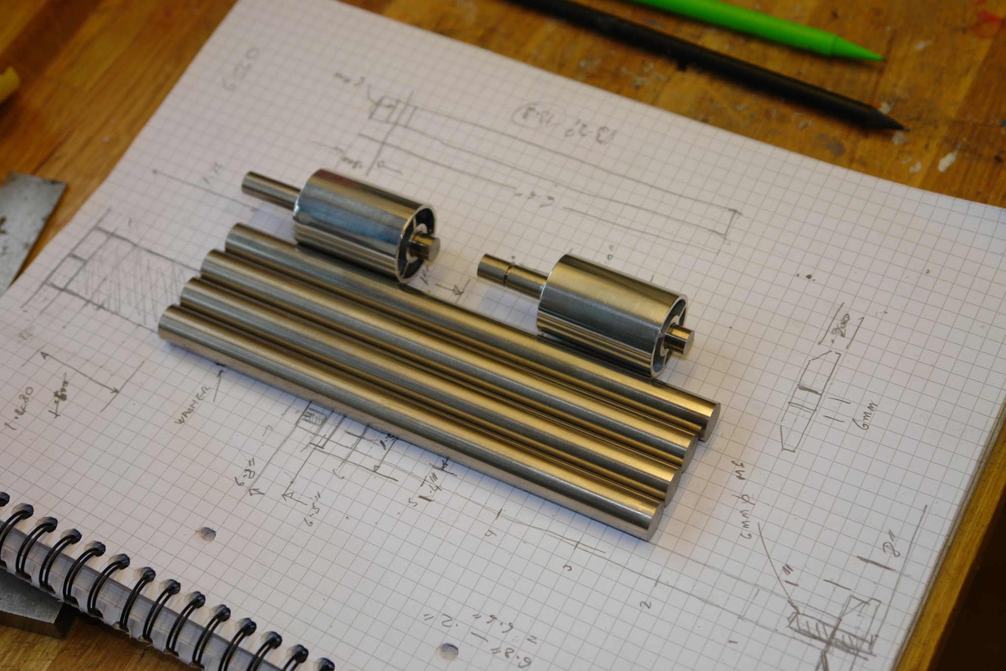
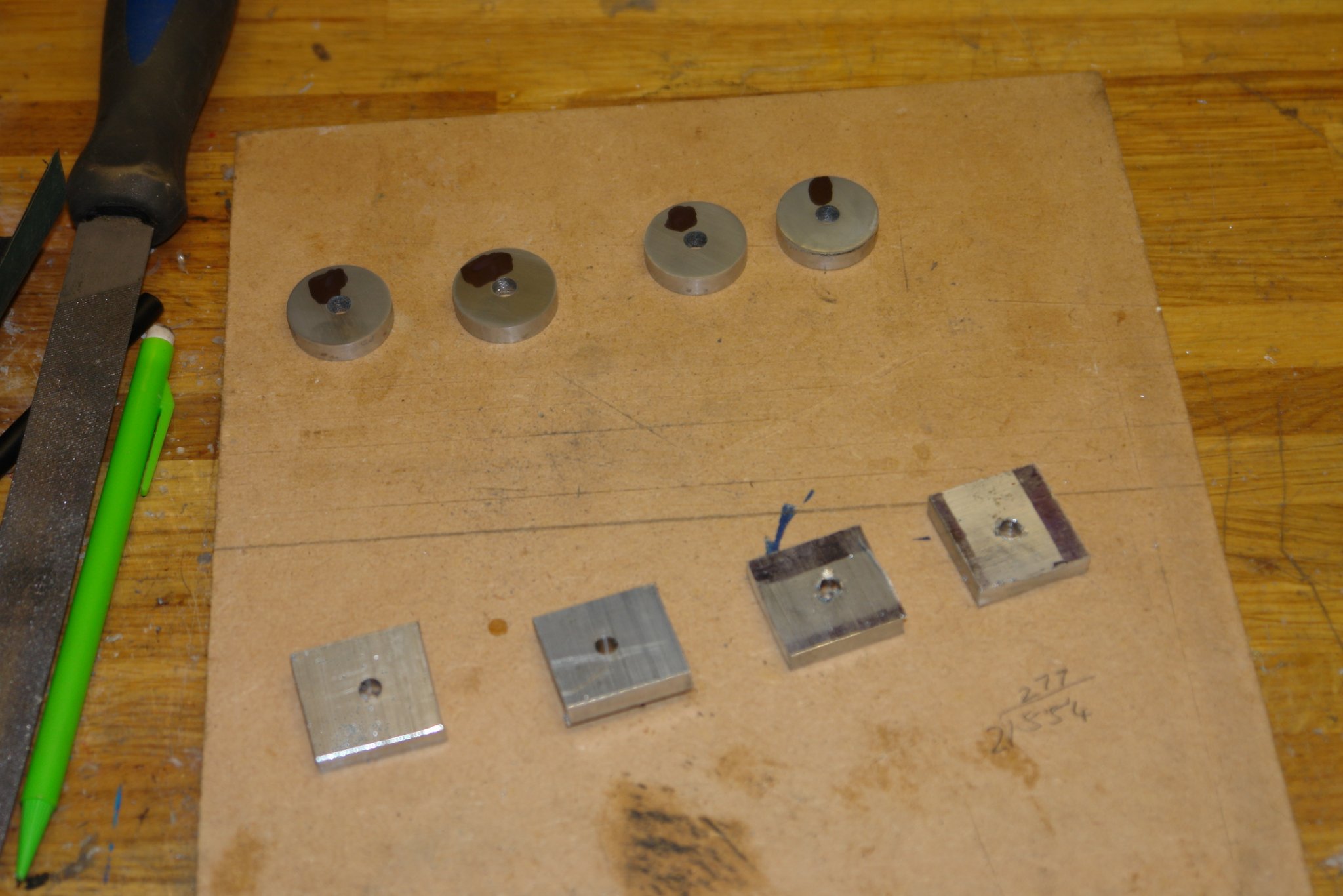
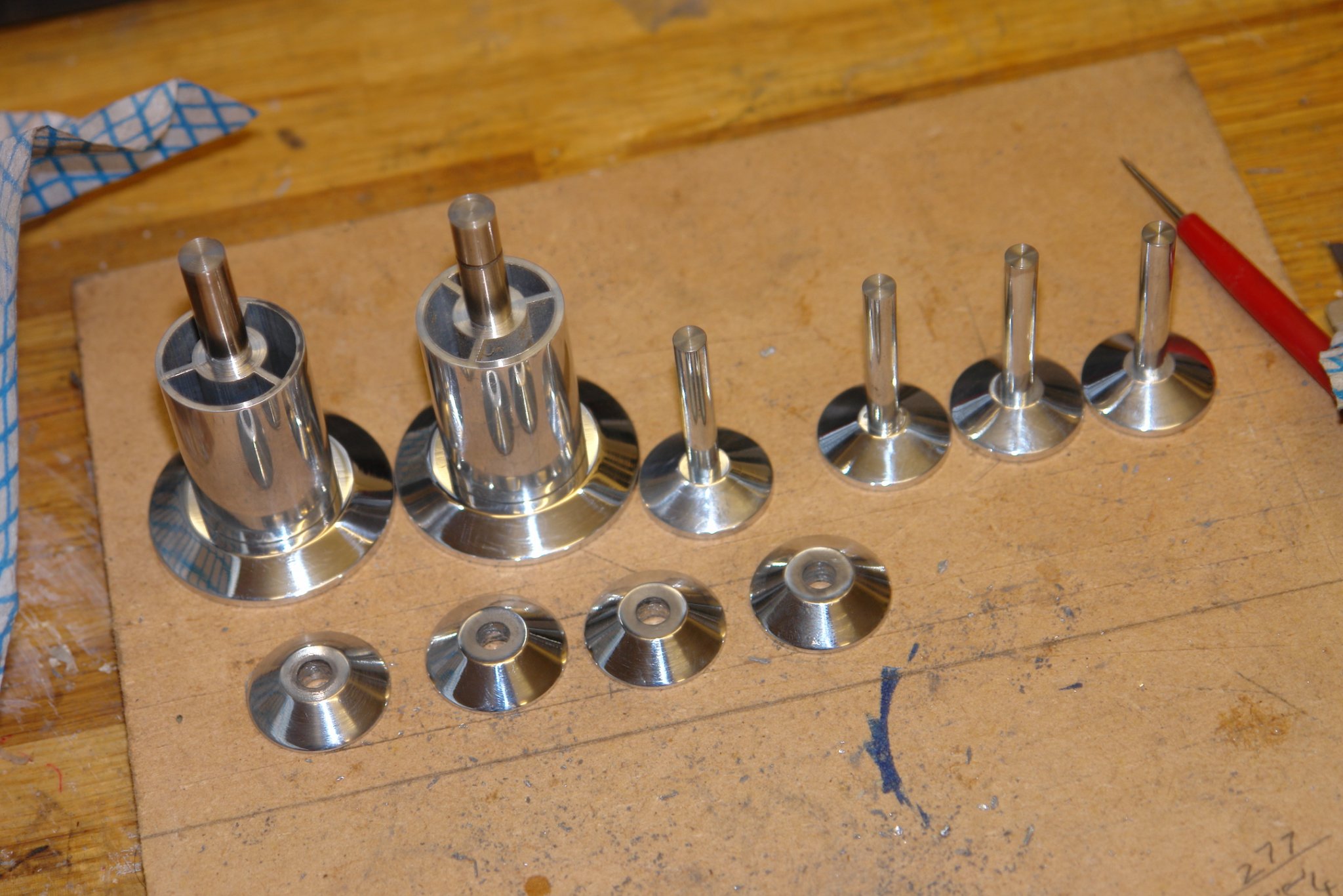
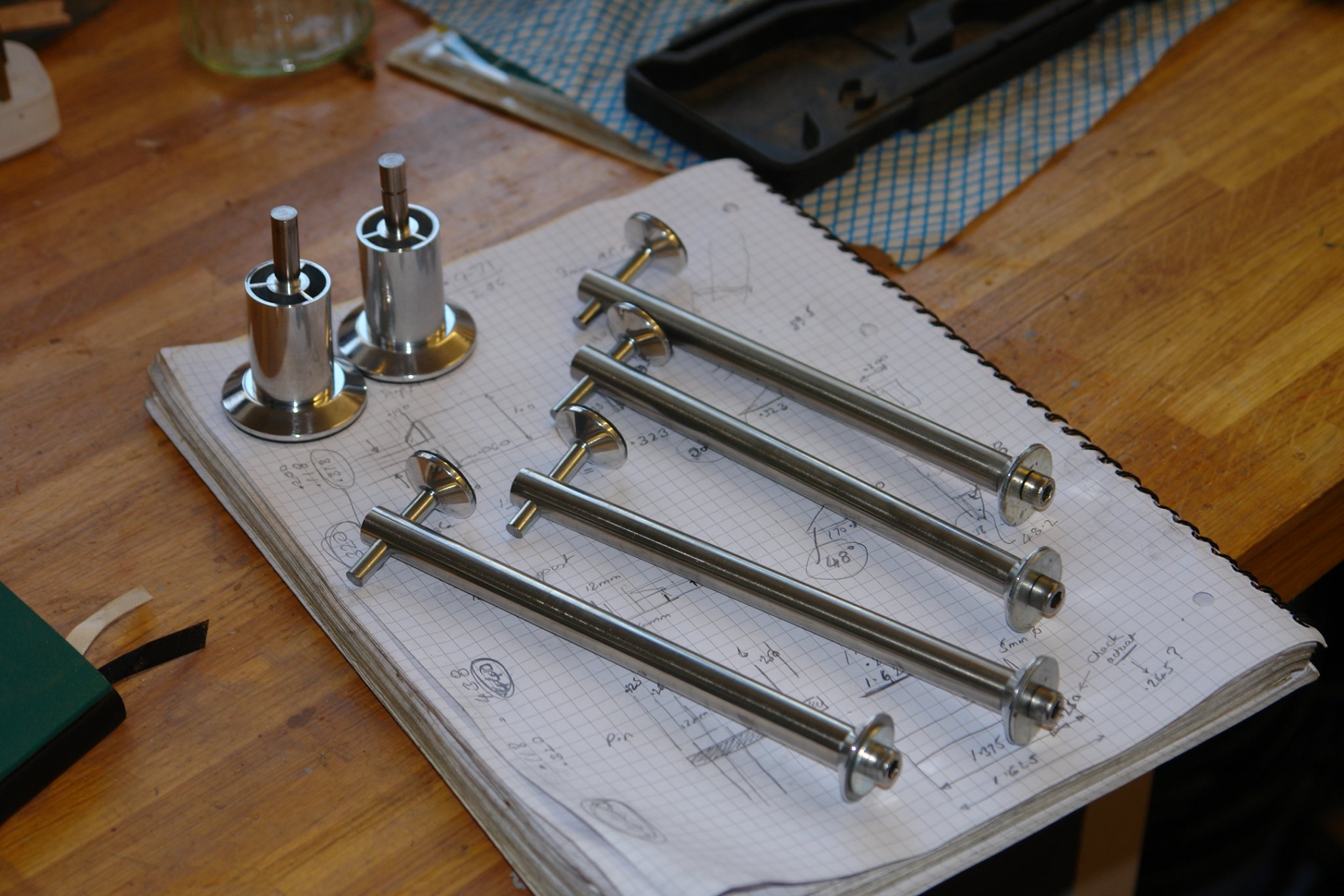
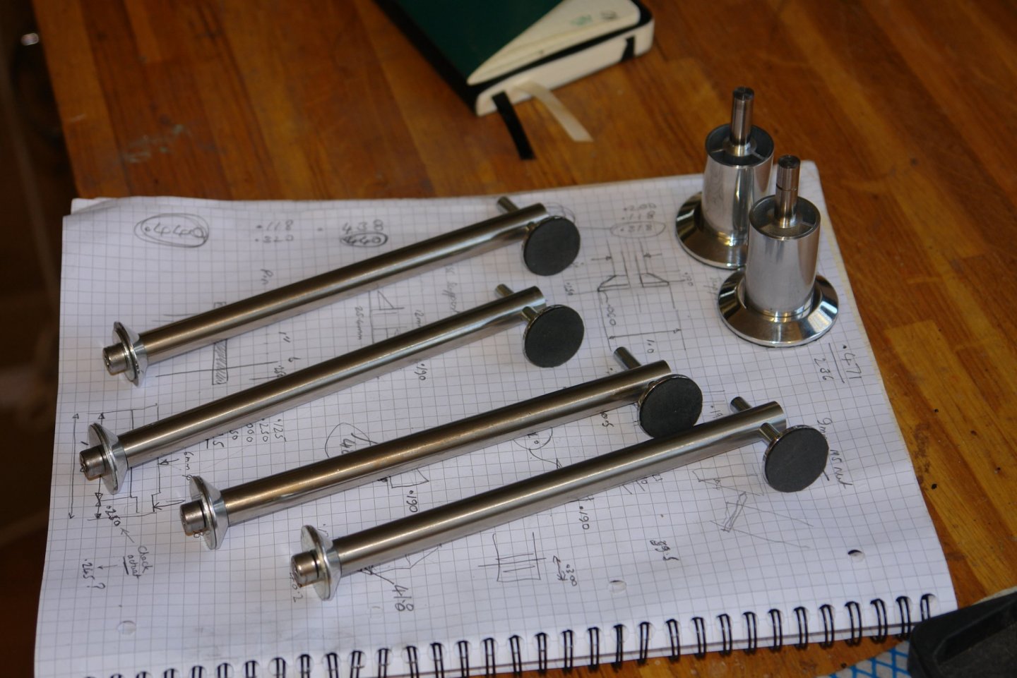
Sometimes the eye strain gets a bit much and I need to return to the full sized world of machining. I needed to complete a project that had been on the shelf for about 7 years and I spent a couple of days doing so. I made 4 steel rods 12mm diameter and just over 150mm long, axially drilled and tapped at both ends. I also drilled a cross hole about 10mm from the upper end. Additionally i needed 2 shorter and larger diameter pieces which I made from a printer roller salvaged some time ago. All were polished. I also needed 8 small and 2 large conical washers, cut from 6mm plate and then turned on a mandrel mounted in the lathe. Once tuned the washers were polished. Once made the parts were assembled and soft rubber pads were glued to the 2 large washers and 4 of the smaller washers. I now need to finish the 7 year old project.


-
The details are really bringing her to life, I know what you mean about fragility - its always a worry when many man-hours have been expended.
- 599 replies
-
- 4
-
-
- sidewheeler
- arabia
- (and 4 more)
-
The shackles turned out really well - must try your technique. She is going along really well and as you say plenty of time to work on her.
-
Unfortunately the assistant chief medical officer said 3 to 6 months this morning. You had better slow the build from 6 hours to 3 hours a day Paul.