KeithAug
-
Posts
3,986 -
Joined
-
Last visited
Content Type
Profiles
Forums
Gallery
Events
Everything posted by KeithAug
-
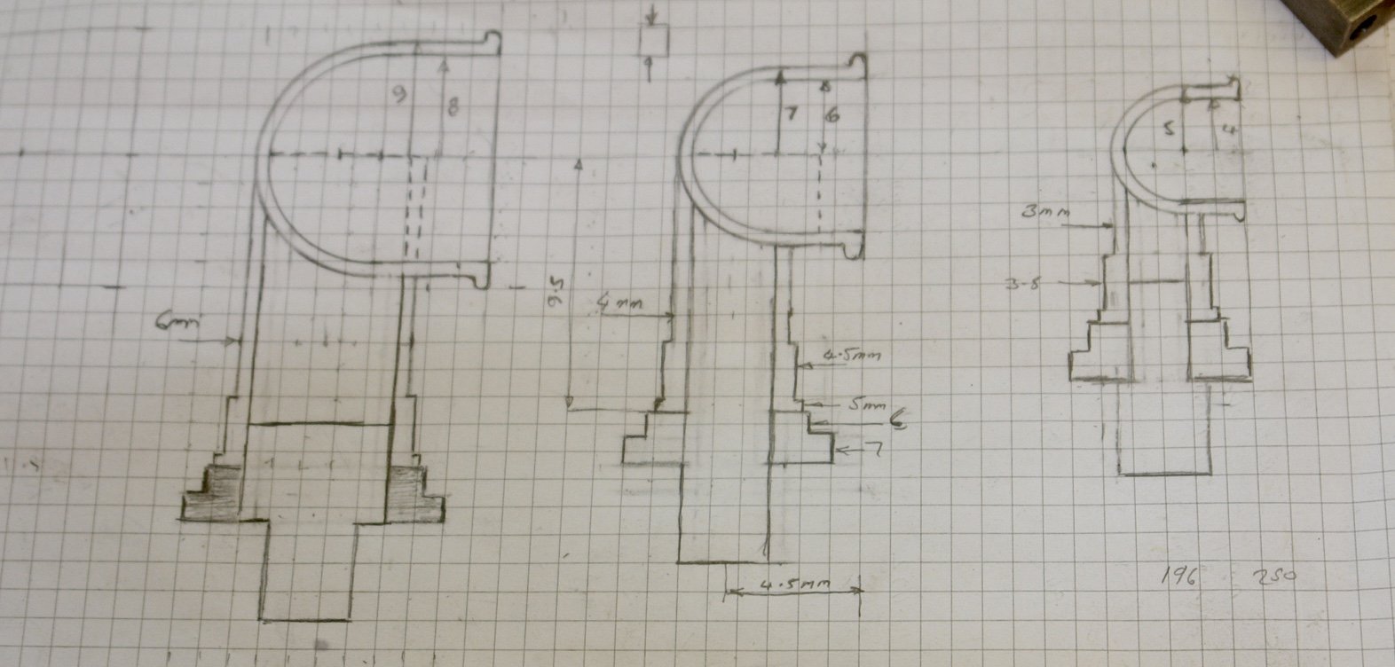
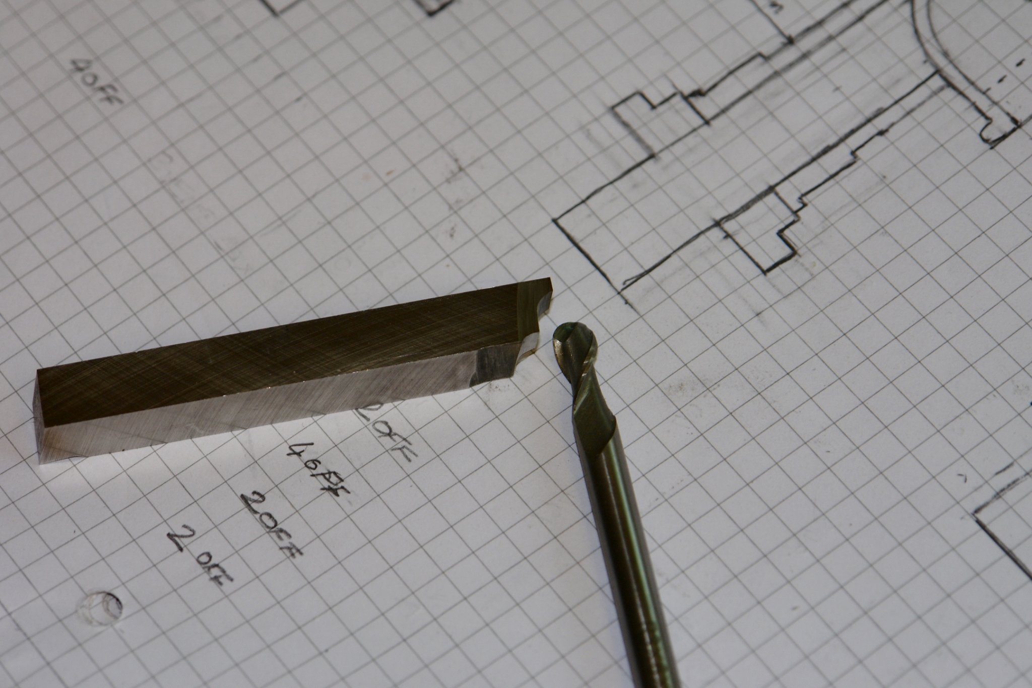
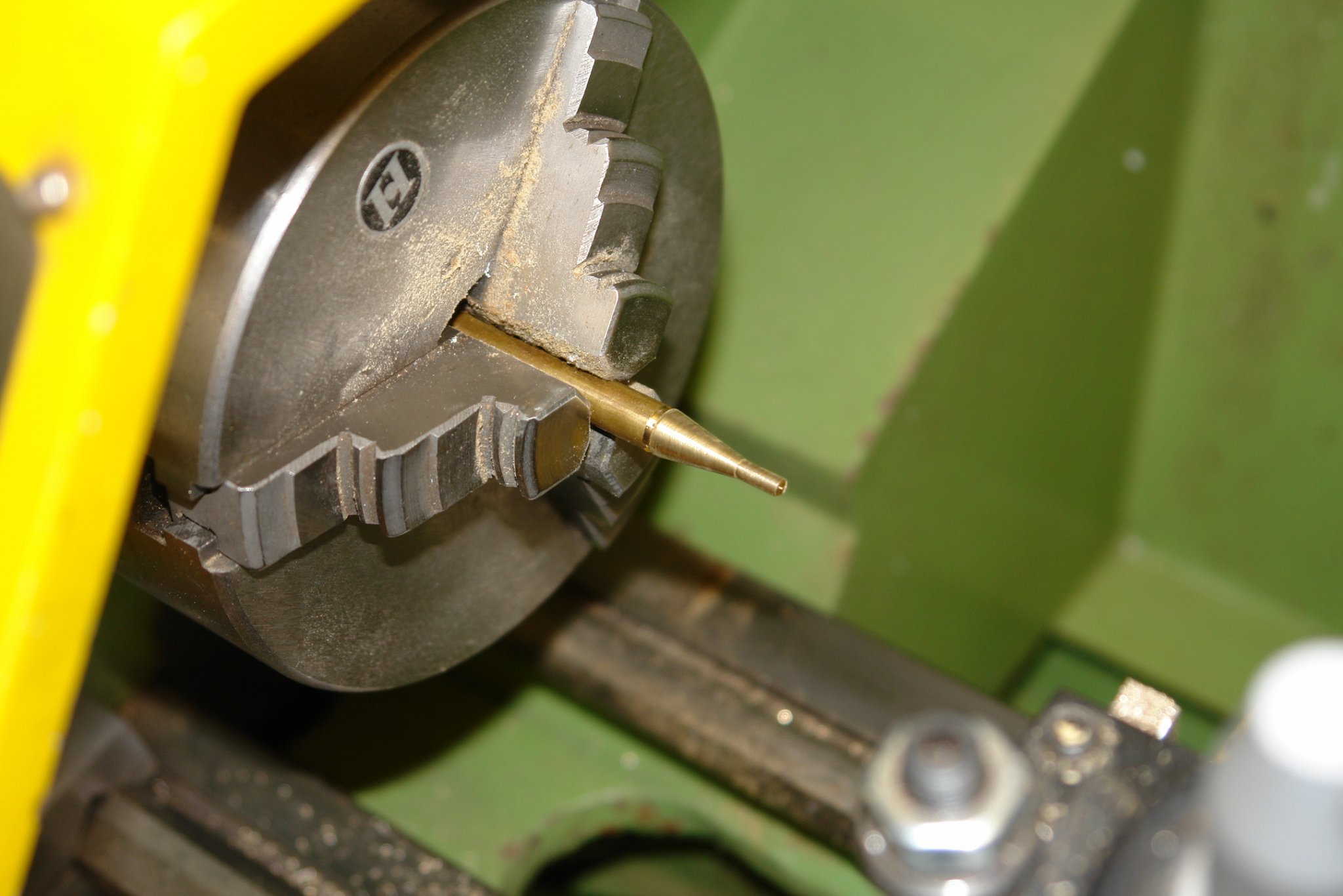
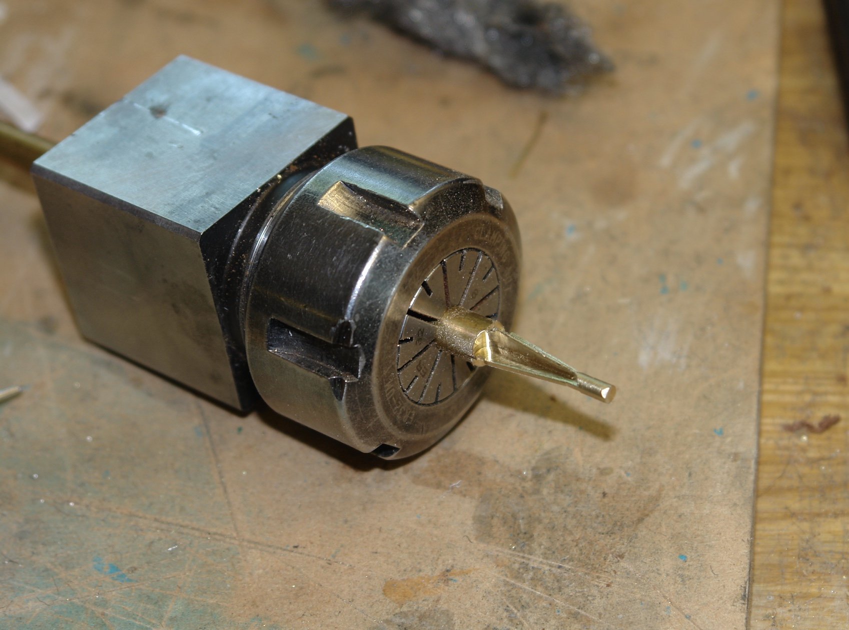
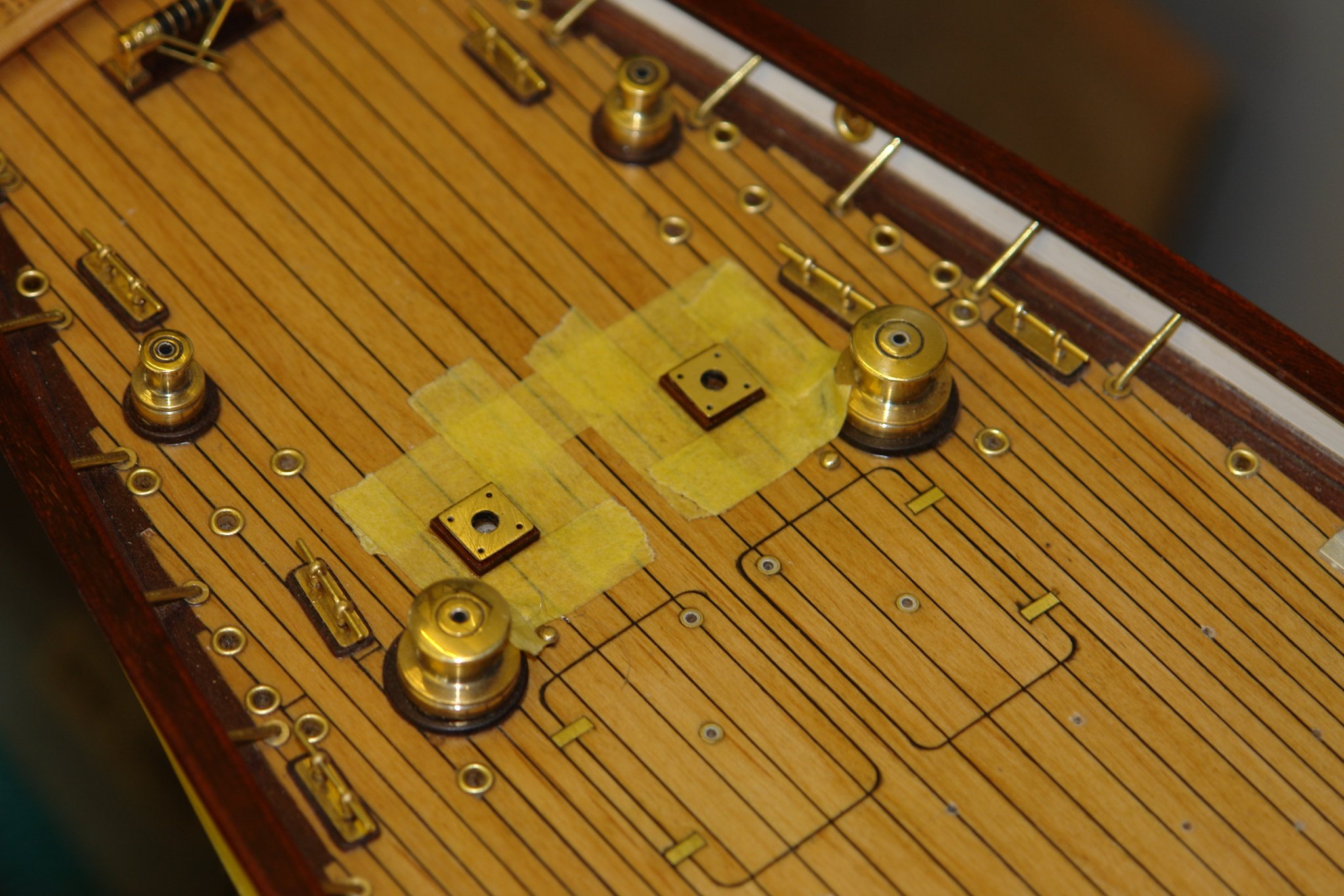
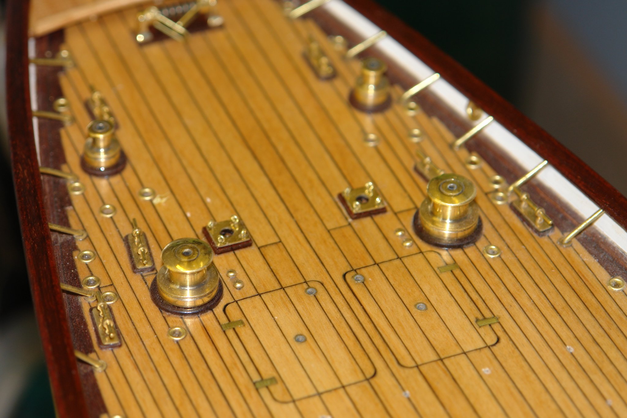
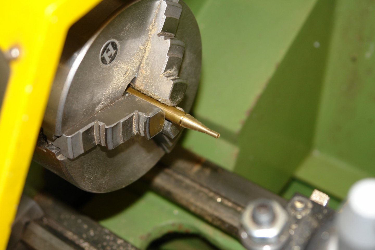
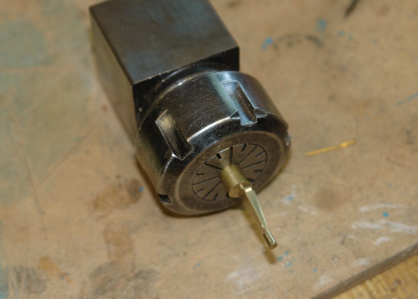
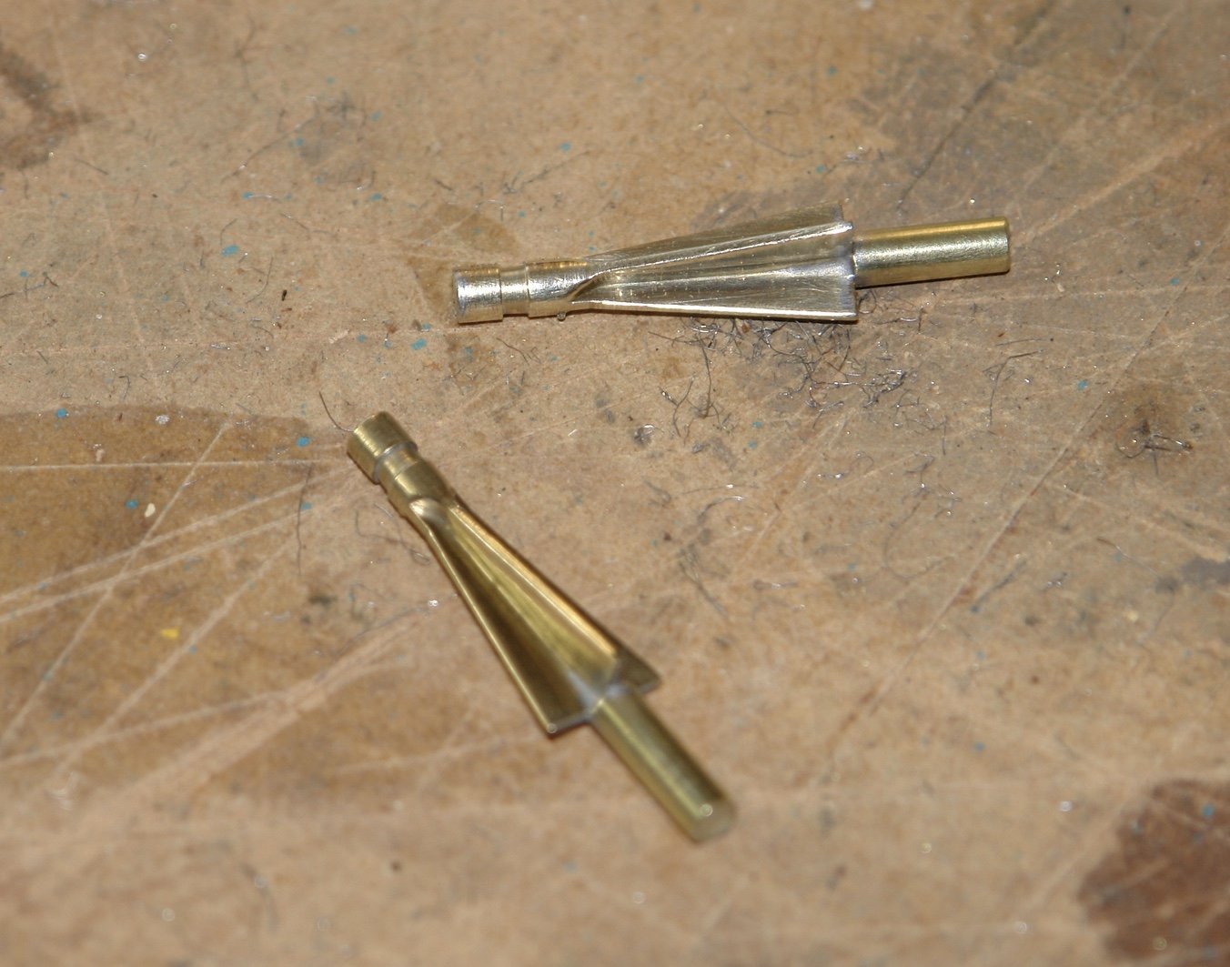
 Pat, Druxey, Mark, Geert, Richard - thank you all for your kind comments. Mark thank you for your feedback. I can see my brackets are worrying you. Before the end of the build I am hoping more Germania photos will come to light and then perhaps we will all find out the purpose. Your guess may well be correct. And so on to the vents. One of the things that attracted me to starting Germania was there plethora of ventilation cowls, seemingly totally over the top and to my eye very teutonic. As usual with me I had imagined them to be much bigger than they turned out to be. Somehow the scaling of photographs proved quite difficult and I had to repeat the exercise several times using about 10 different photos before I was happy. The following photo is the one showing most vents but there are number more. The good news about the vents is they are a fairly simple shape - essentially the mouth is a dome ended cylinder while the stem is another cylinder. My mammoth attempt at scaling convinced me that three different sizes of vent exist. The following sketch reflects these. Sorry but the scale is metric and each square is 1mm x 1mm. The larger size has a 8mm (.32") mouth and a 6mm (.24") stem - 4 of these are required. The middle size has a 6mm (.24") mouth and a 4mm (.16") stem - 12 of these are required. The small size has a 4mm (.16") mouth and a 3mm (.12") stem - 2 of these are required. I plan to fabricate them as follows:- Step 1 - is to take a round bar and machine the outside diameter to size. Then drill a hole just over half way through the bar. Step 2 - is to take an end mill the same diameter as the the stem outside diameter and widen out the hole to a depth equal to the bars radius. Step 3 - is to turn the outside profile of the vent mouth using a profile tool. Step 4 - is to insert the stem and solder it in place, Followed by boring the inside of mouth using a ball ended milling cutter. For each size of vent the wall thickness will be 0.5mm (.02"). I made the 3 profile tools by grinding high speed tool steel by hand, it took time and patience to get them right. The next photo shows the profile tool for the middle sized vent. Here is the profile tool with its corresponding ball ended mill. Tomorrow I commence the production run - hopefully by Sunday evening I will have 18 vents.
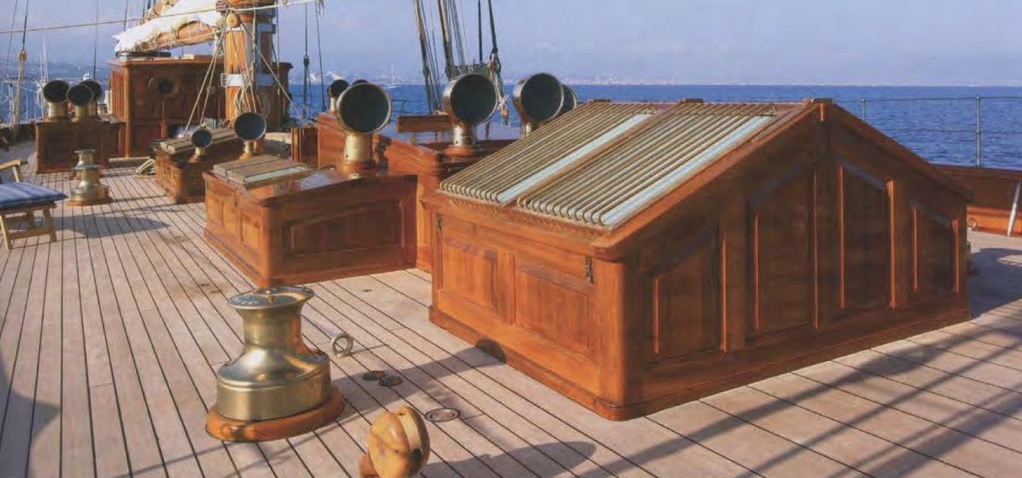

-
Very interesting Eberhard and a very good result. What programme do you use to read the image and create the code needed to drive the laser cutter? You probably covered this earlier but I obviously missed it.
-
Very neat looking sails, inevitably you suffer from the perennial problem, namely that the wind does not blow them into an elegant curve. Are you planning to give them shape and if so how? On the point of the lockdown being lifted is this a Cambridge thing? Down here in West Sussex the only change seems to have been we can go on longer dog walks - still very few non-essentail shops open and definitely not cloth shops.
-
Somehow I lost touch with your build Geert. However it was great fun catching up. It is always a pleasure to see how well you manage with basic tools. Excellent result.
- 219 replies
-
- 1
-

-
- smack
- cross-section
- (and 2 more)
-
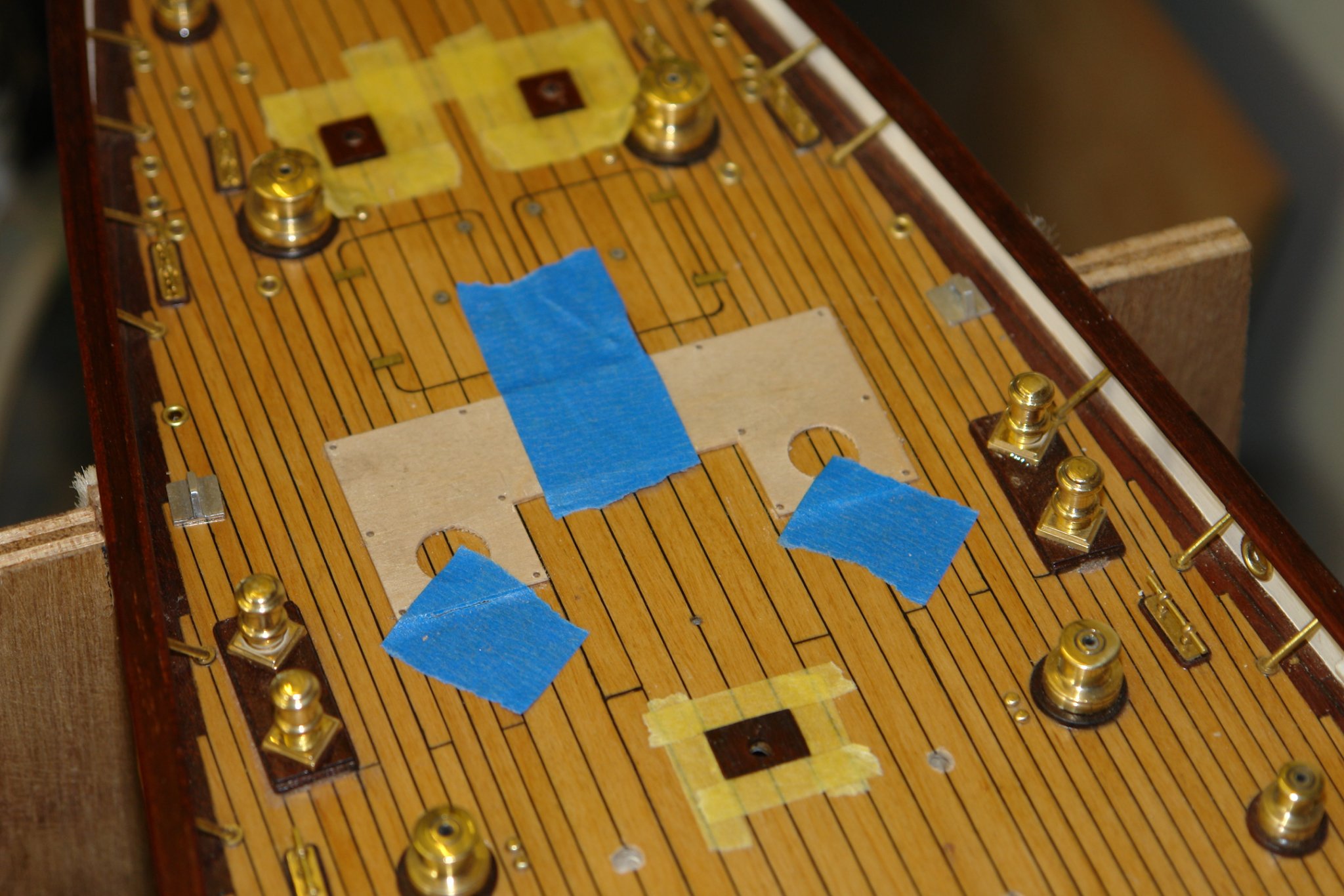
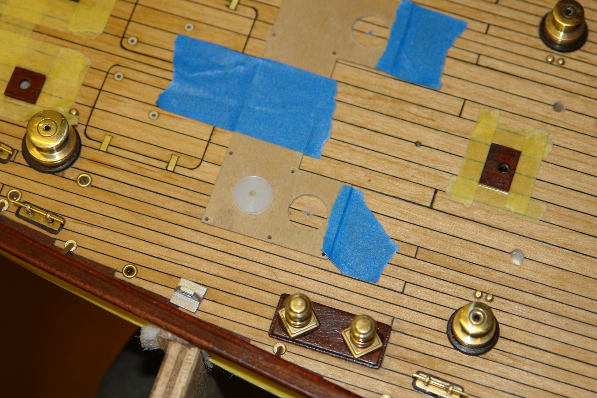
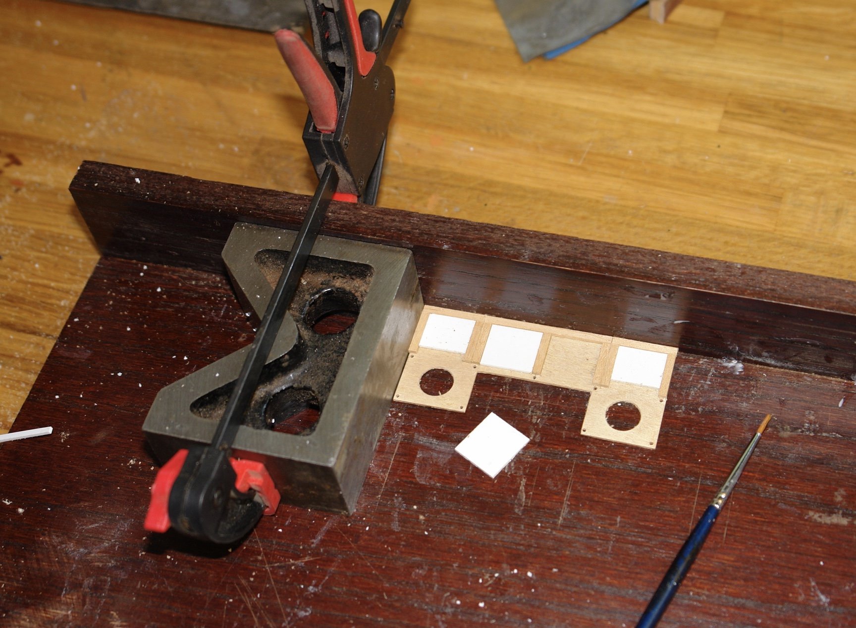
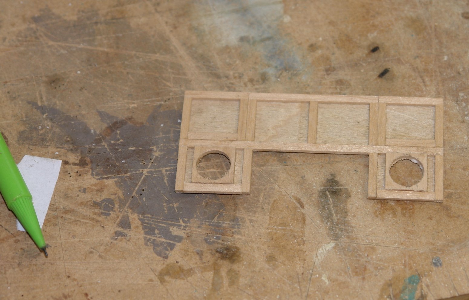
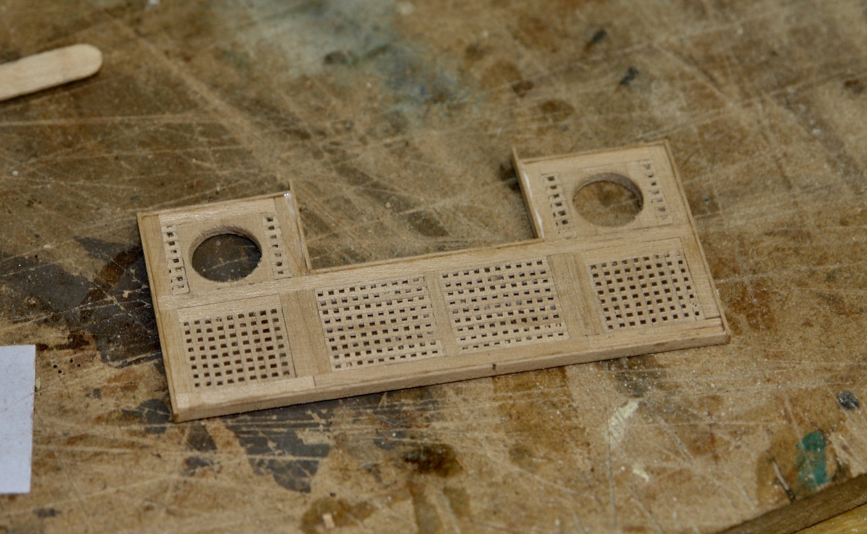
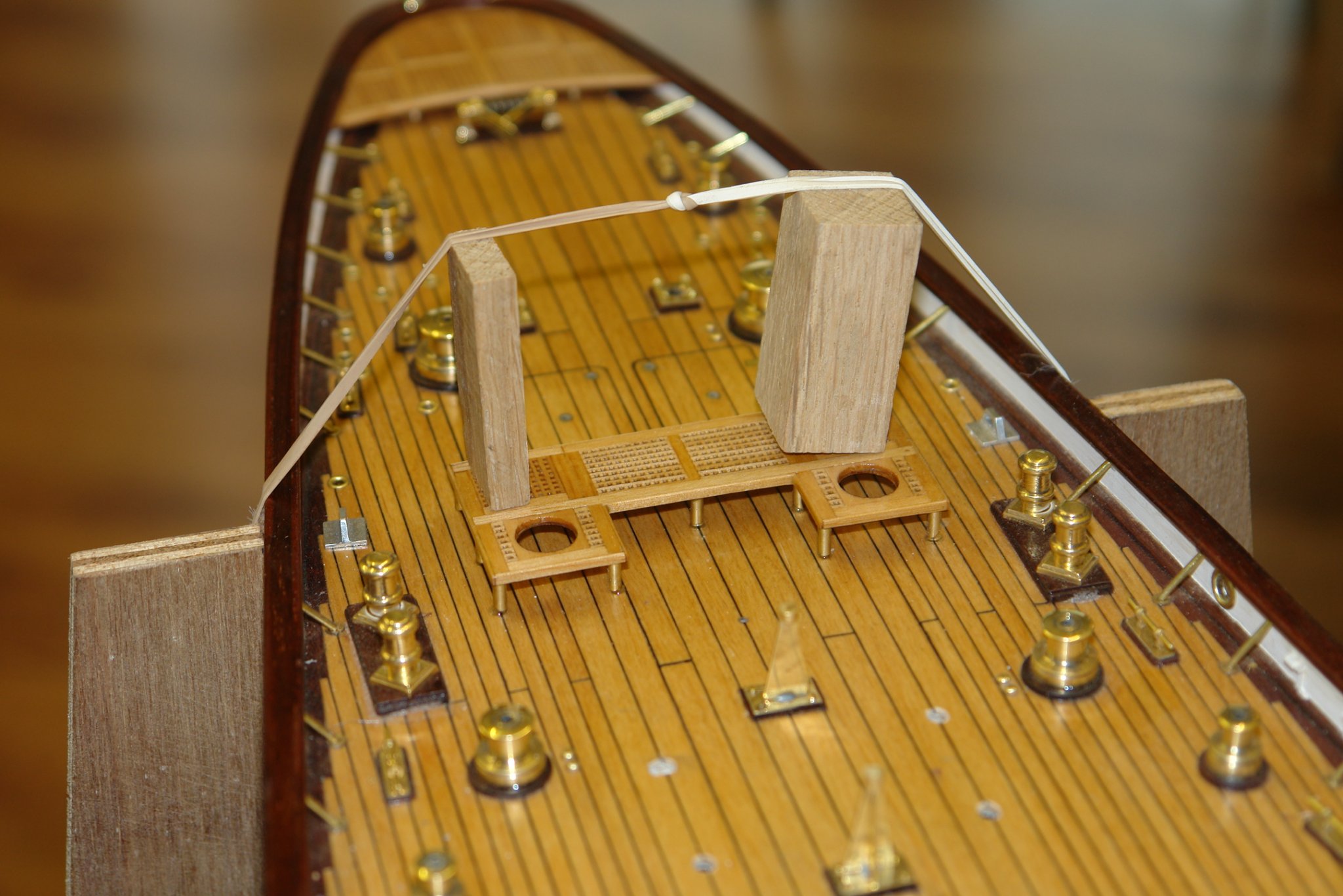
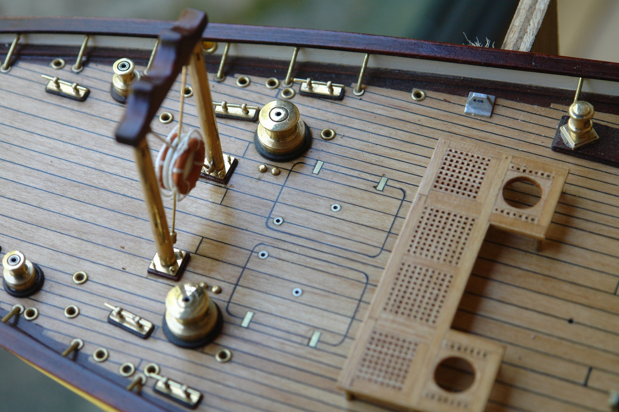
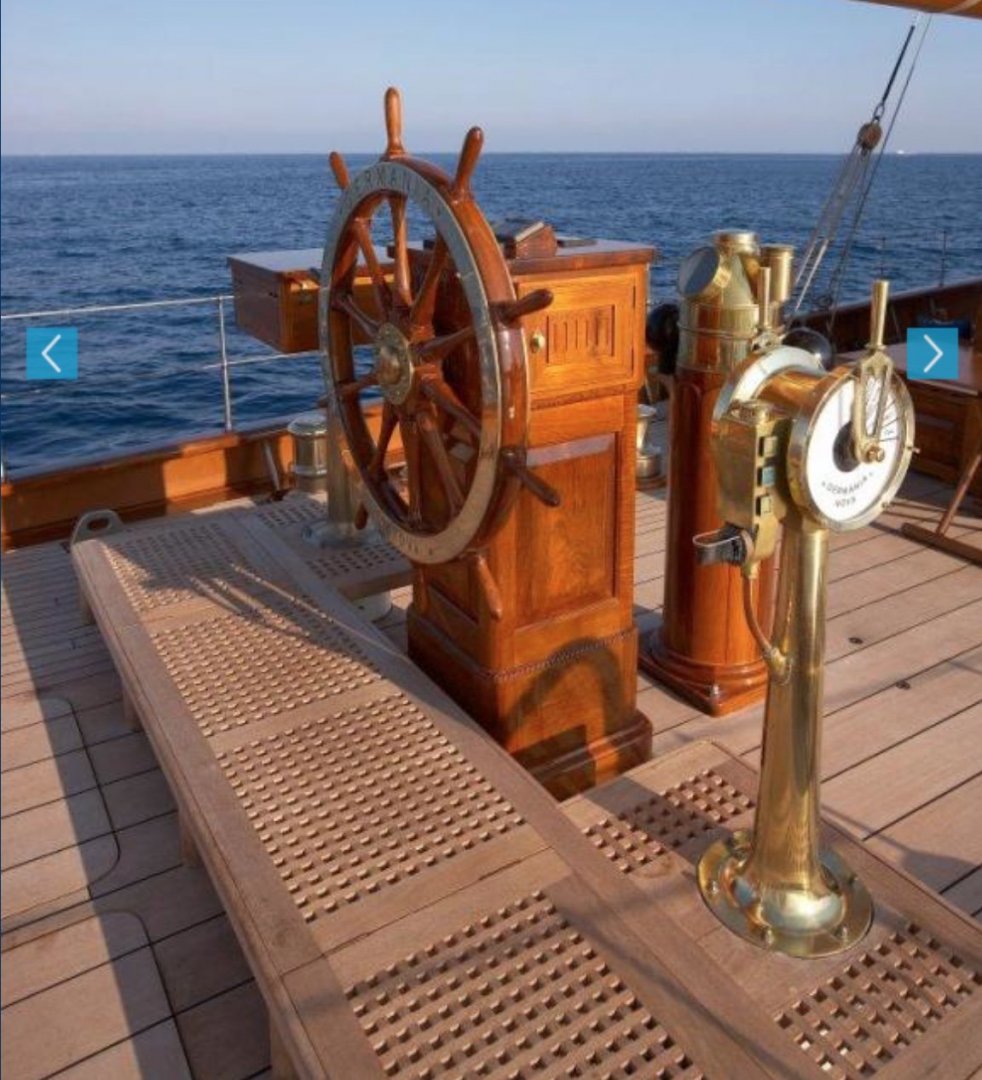
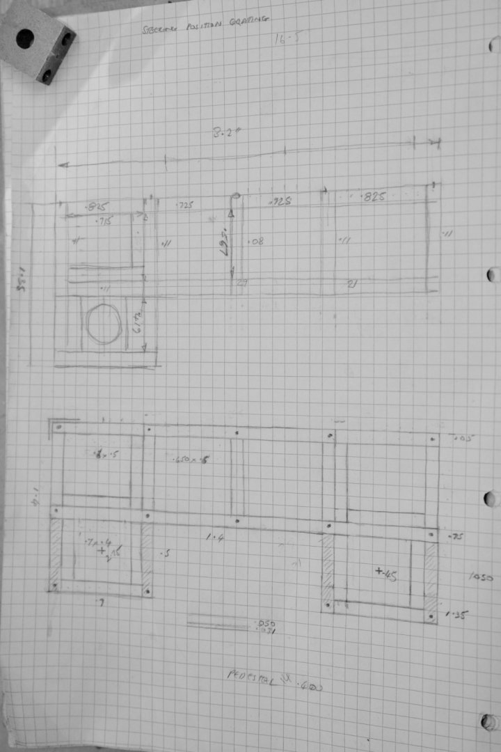
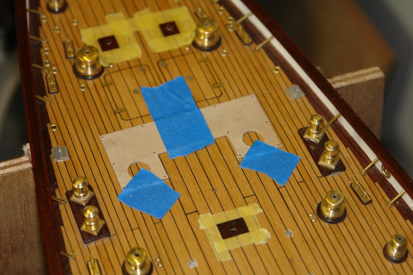
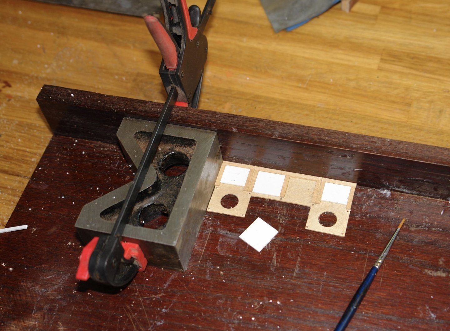
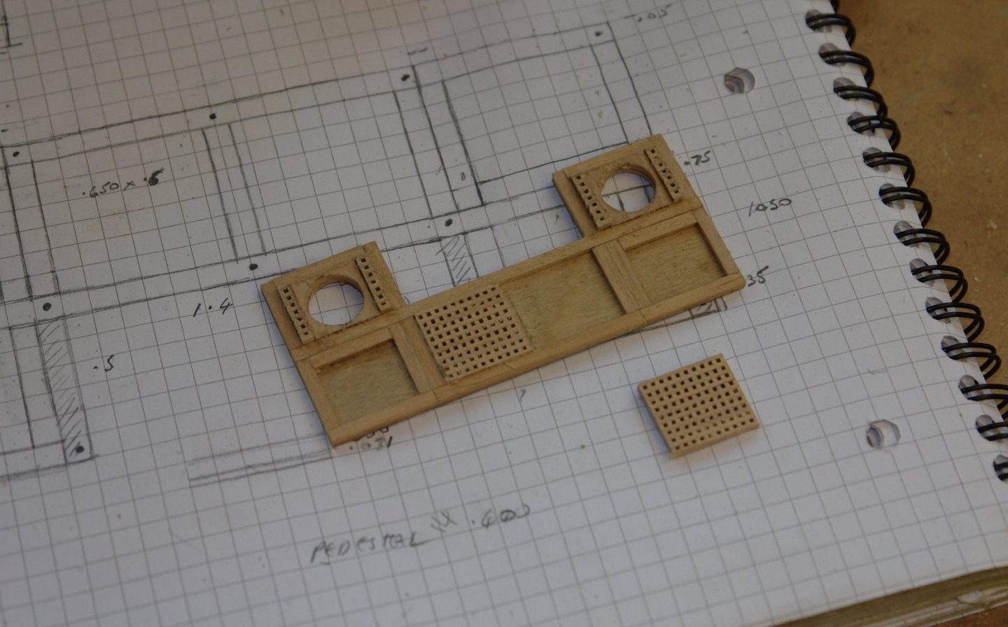
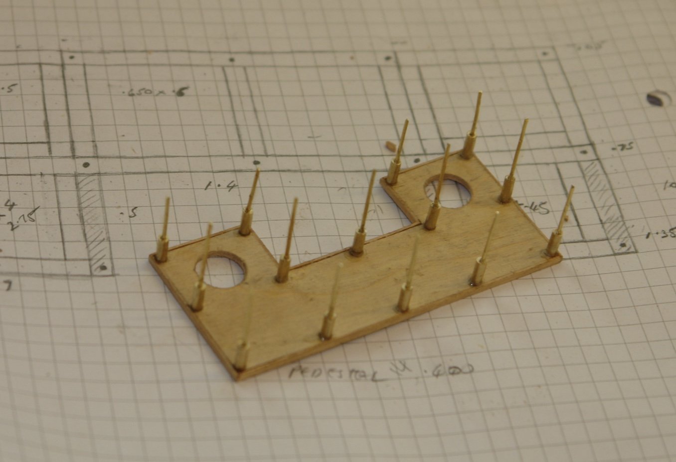
Final diversion before vents start first thing tomorrow. The helmsman platform forms a shallow U around the wheel. Using the photographs I was able to get a very good approximation of size. From this I created a sketch. The overall size is 3.2" long by 1.35" wide. The thickness is .080". The gratings are too fragile to be structurally sound so, as with the case of the stern platform, I built the platform on a 1/32" ply backing. The legs positions were drilled through on the ply backing and then this was used as a template for drilling the deck. A plastic disc was turned to fit the large circular holes and then this was used to drill the hole centre positions on the deck. I then started to build the framing on the ply backing. Plastic card was cut to create spacers for accurate positioning of the frames. I had planned ahead when making the grating for the stern platform and had enough to complete this platform. Edge pieces were then installed to mask the edge. The next photo was taken in the rough state prior to sanding. The small size of the grating holes makes the presence of the backing undetectable. Legs were then turned to diameter and length. Diameter .092" and length .250". the legs were drilled through to take .040" wire. This wire located in the holes in the platform and deck. its not obvious from the photo but each row of wires is a different length so they can be progressively inserted in the deck holes. They are glued in place using CA. Once the platform had been sanded and sealed it was glued on the deck (using makeshift clamps). Then a few pictures were taken.


-
Very passable Gary ( I am practicing understatement) - thanks for the tip about the fishing lead wire
-
Well Jon perhaps it is possible to make a silk purse out of a sows ear. Coming along nicely.
-
Thank you for the journey, I really enjoyed following along. A a child I always wanted to build a river boat - maybe I watched too many westerns. Anyway - thank you for allowing me to realise my youthful ambitions by proxy. What next?
- 599 replies
-
- 4
-
-
- sidewheeler
- arabia
- (and 4 more)
-
Thank you Dirk - I hope you don't mean it put you to sleep. Actually I prefer Gin - Bombay Sapphire.
-
Mark - My plan is to model the boat with her sails up. The owner may be wealthy but he doesn't like to bounce his best crystal, silverware and Bollinger on to the deck as she heals. He doesn't mind the financial loss but the additional skivvies necessary to clean the deck take up too much room. Eberhard, Druxey, Keith, Pat, John, Steve, Richard - thank you.
-
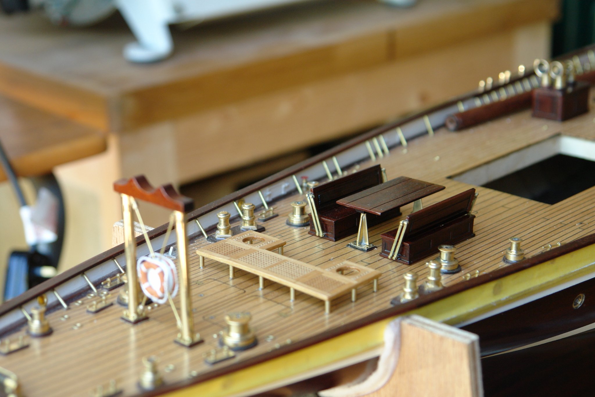
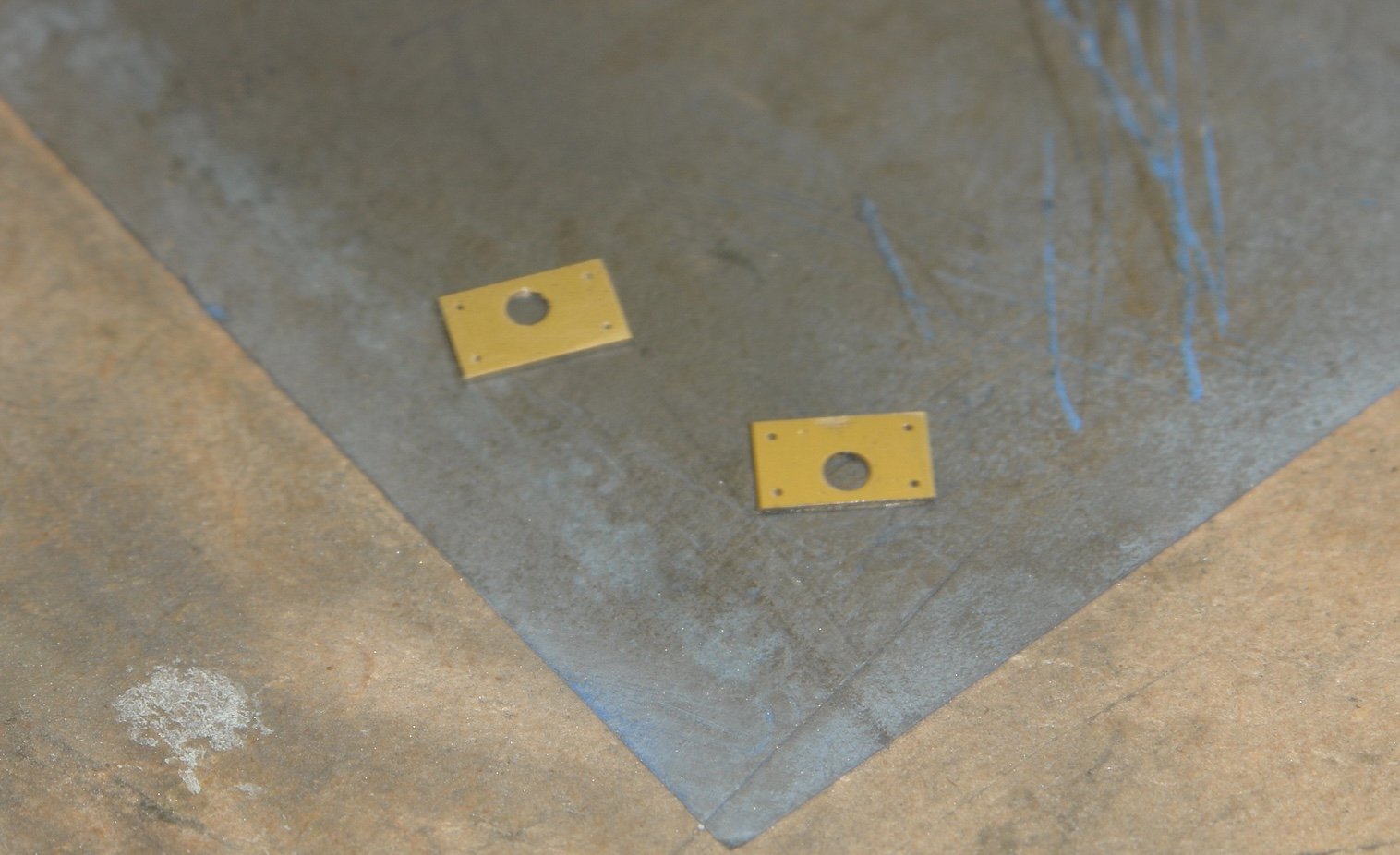
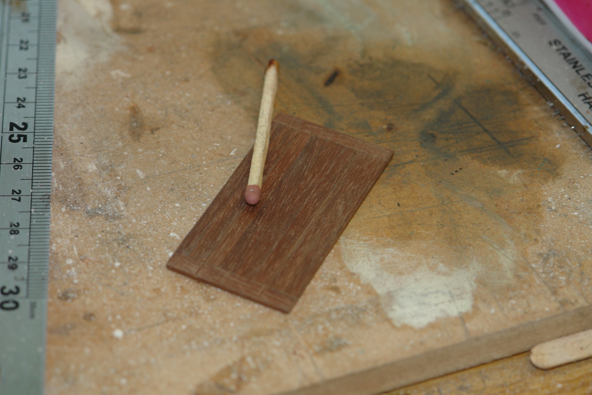
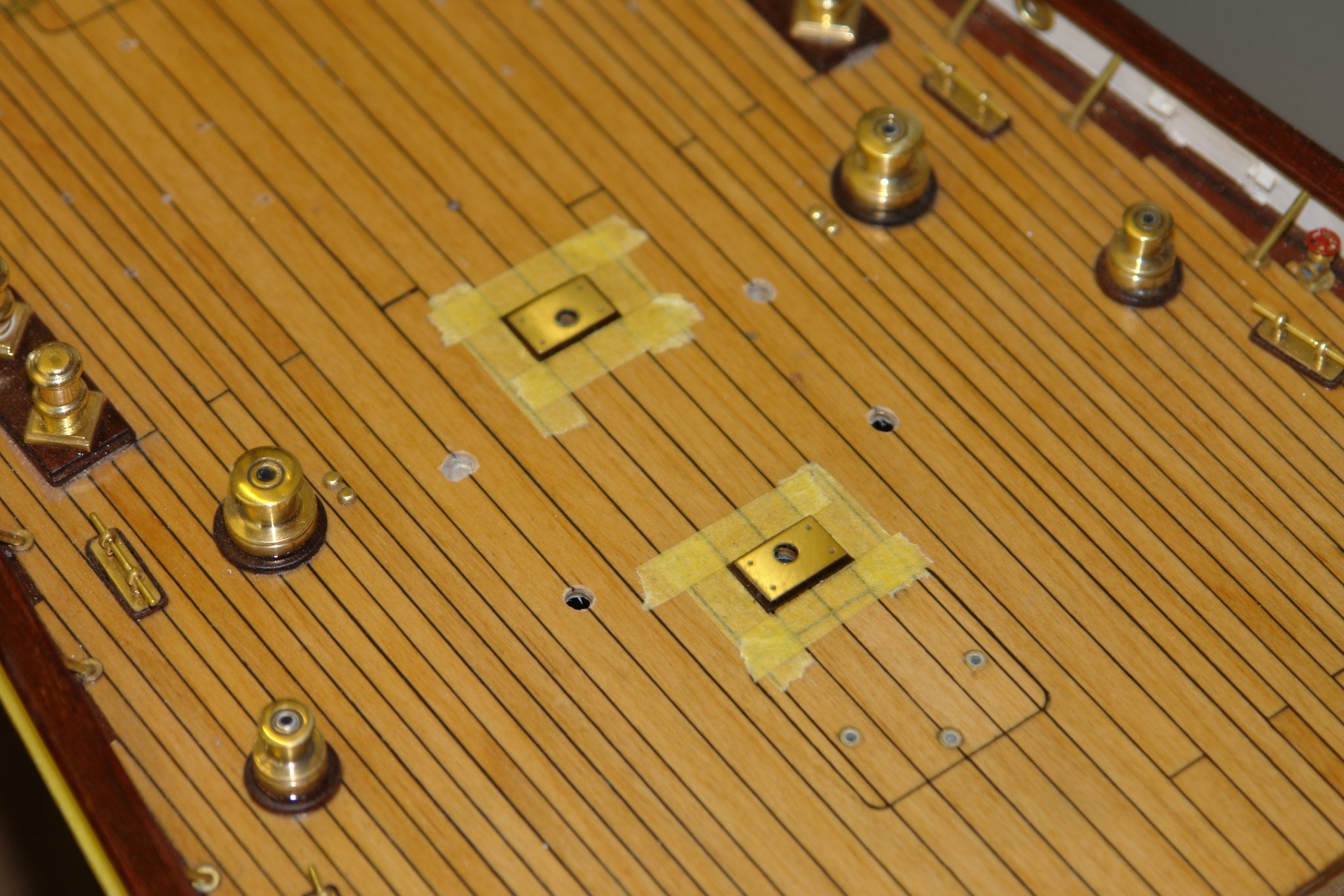
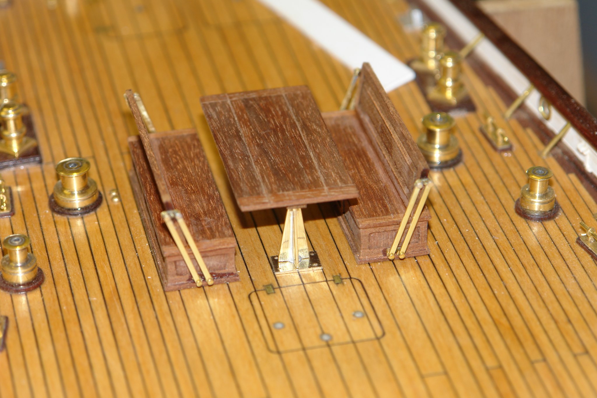
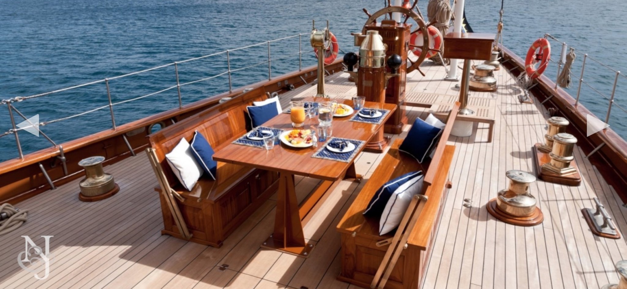
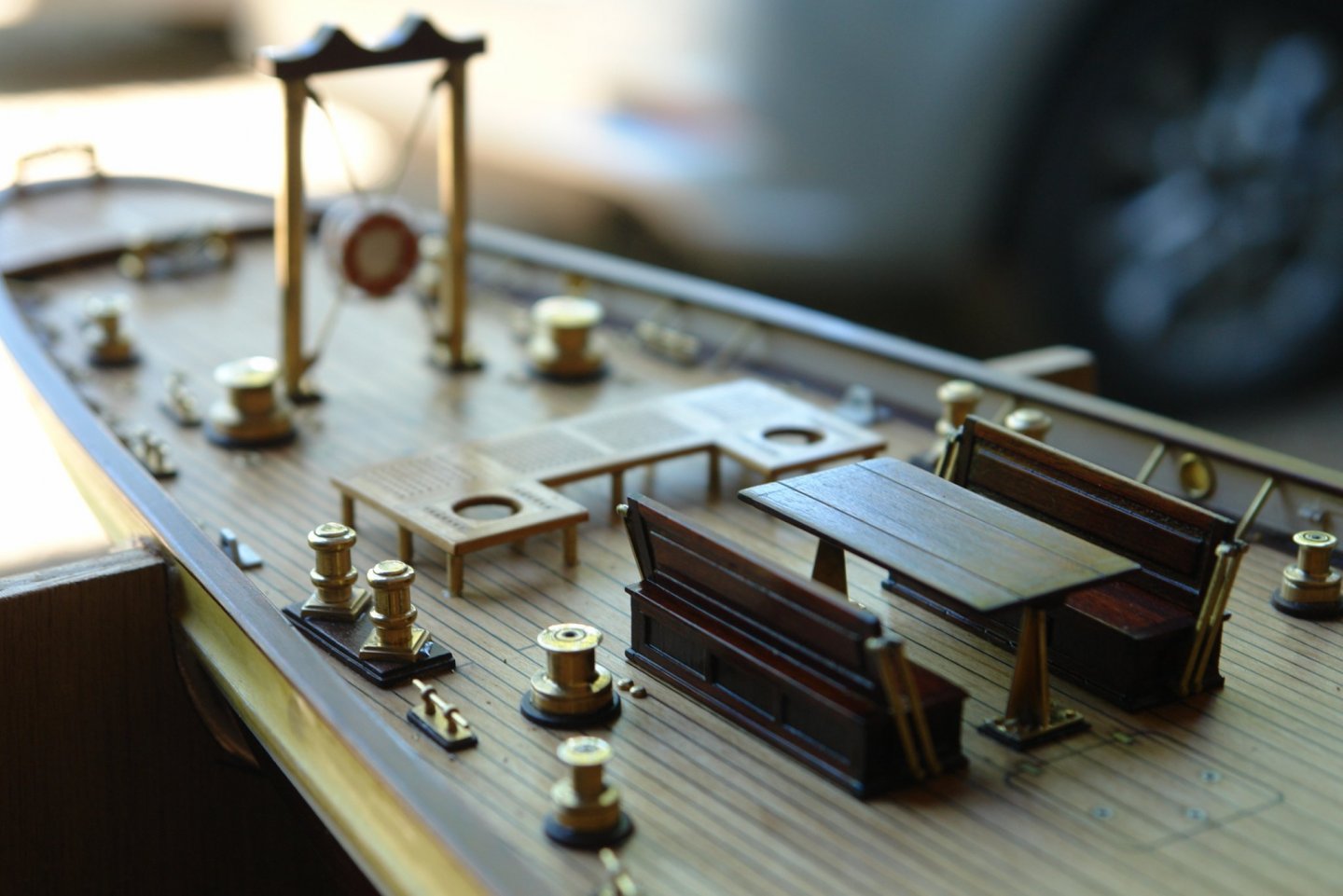
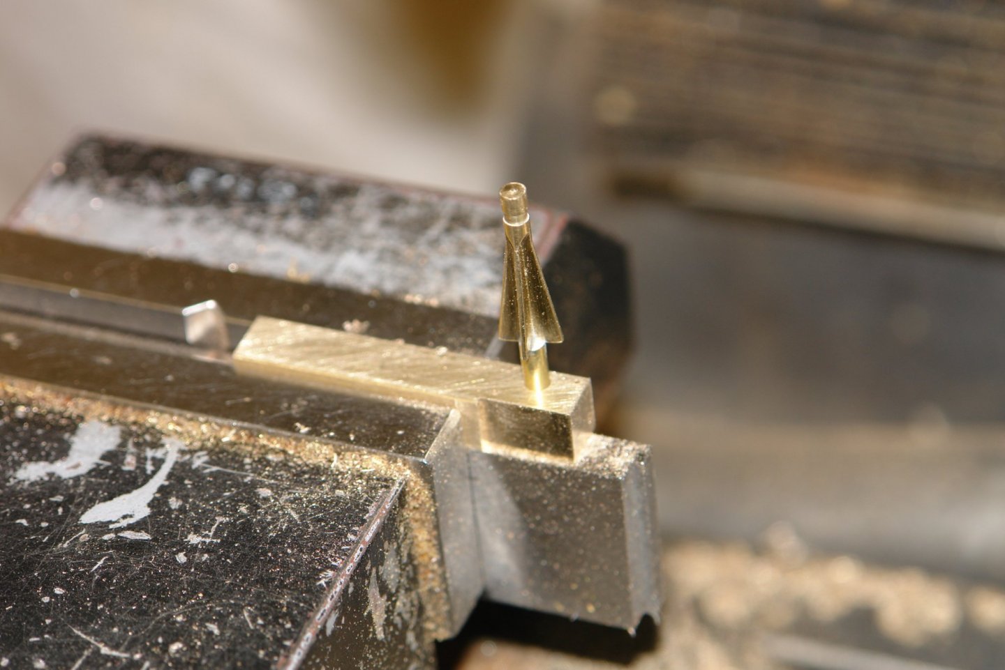
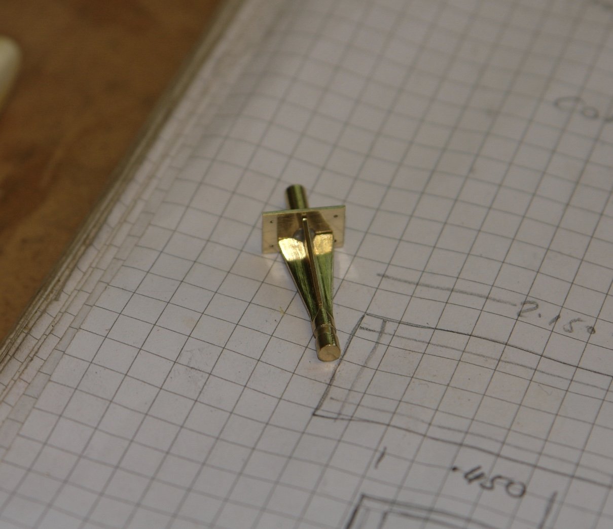
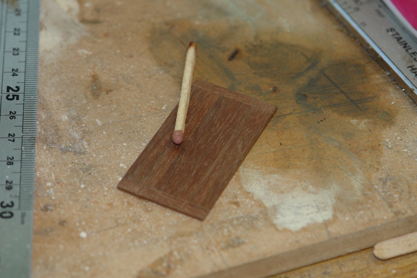
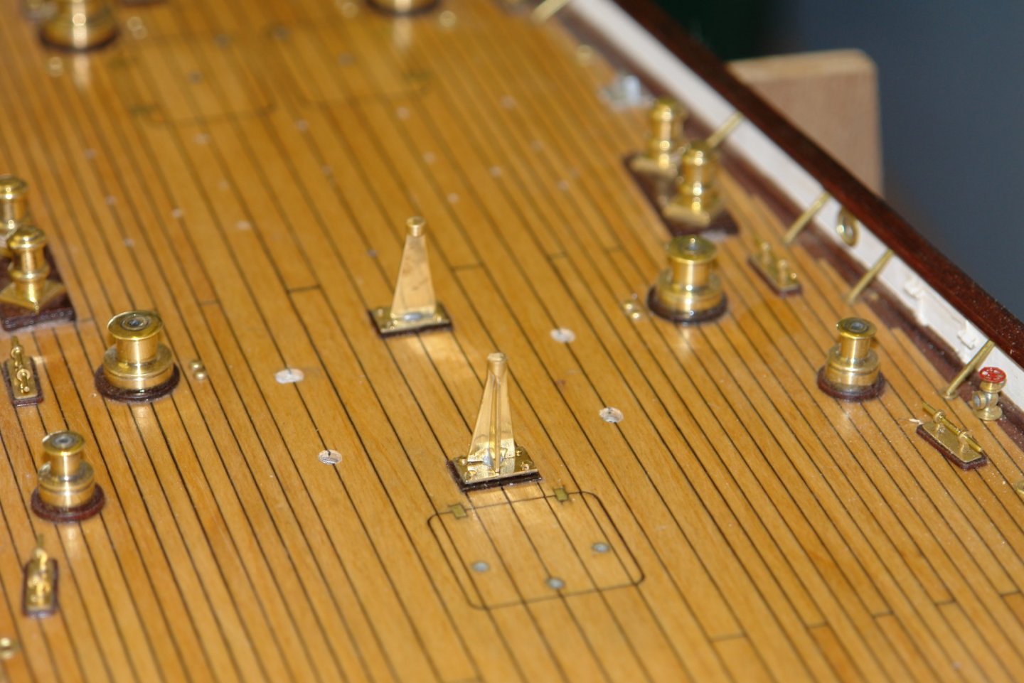
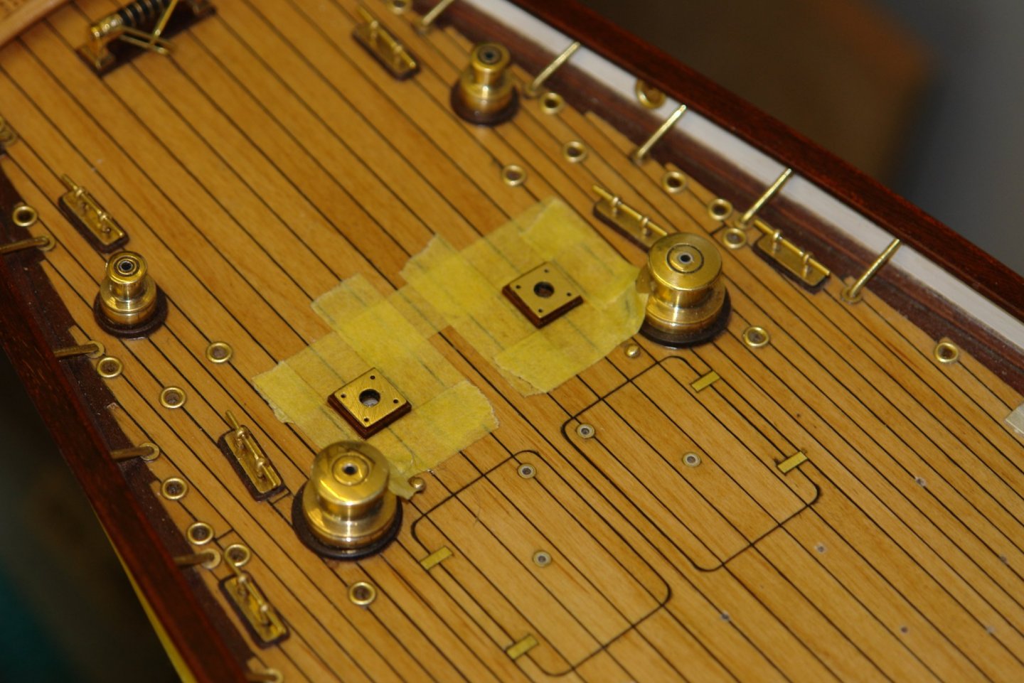
Thank you Richard. Unfortunately not a very productive week. Really quite hot and a lot of garden jobs to get on top of. I got on with the deck dining table. This has a flanged support leg - quite unattractive in brown paint but much better in brass. .8 1.1 2.1 I turned the 0.80" long leg as a cone. This was then transferred this to the mill to cut away the excess metal to create the triangular flanged leg. The leg was then parted off to length and a 1/8" diameter spigot was soldered on to the lower end to allow it to be mounted on the deck. I cut the base bracket from a piece of bar and drilled a 1/8" hole for the spigot and 4off .025" holes for the mounting bolts. The base plates were then slit to thickness and then cut off and polished. The table top is 1.1' x 2.1' with the two leaves extended. This was made from .060" planks with scribed lines to simulate the leaves. Wooden plinths were mounted on the deck and given a couple of coats of poly before the brass plates were added. The legs were then added followed by the table top. While I was at it I mounted the base plates for the crutch. 4 eyes are located at each corner of the plate - very small and made from .020" diameter brass wire. I know I said that I was going to get on with the vents - but I got diverted.


-
John, Keith, Pat, Gary, Phil. Thank you for the feedback and the good advice re photo stacking - I will need to do a bit of reading up on the technique - I feel an internet search coming on.
-
Eberhard - no I have not but I can see that it would work. The basic problem I have is that I keep an old camera in the workshop and not withstanding the good level of artificial light it isn't anywhere near as bight as outdoor natural light. The less than ideal light coupled with a hand held 15 year old bridge camera means that I create the problem. What I need to do is move the model outside, mount my new camera on a tripod and shoot with a small aperture That should give me a greater depth of field. But failing that I'll have a look at your suggestion.
-
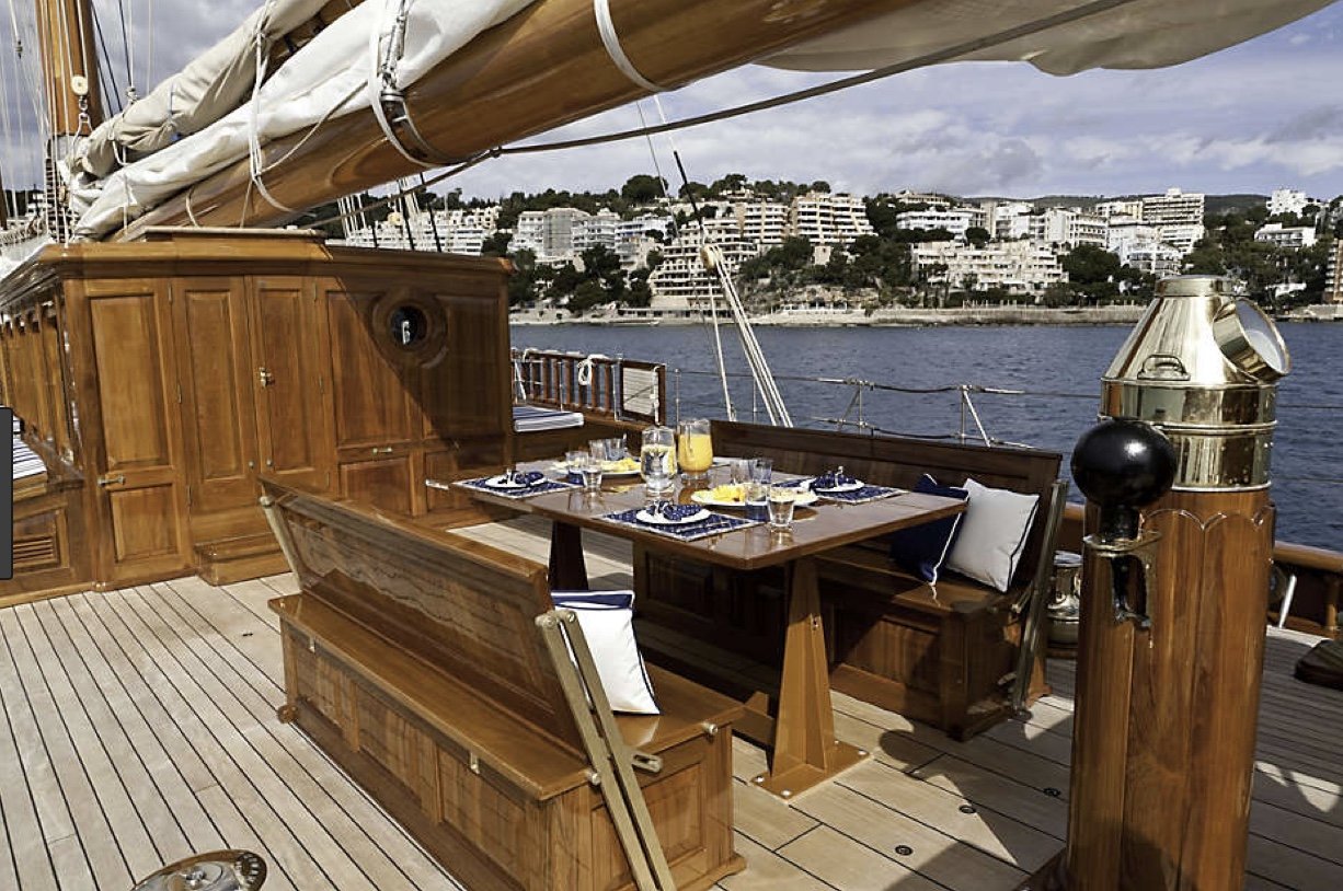
Eberhard - yes I agree. I can see that the Germania pivot arrangement will keep the back more upright than a simpler arrangement of a single pivot point with a fixed position back. Presumably they felt that a more upright seating position was beneficial, particularly when dining. Keith, I find the camera does not cope well with getting the the whole deck in focus. I want to get all the vents made and fitted over the next few weeks and then I'll have a go at a few overall shots. Thank you for the feedback
-
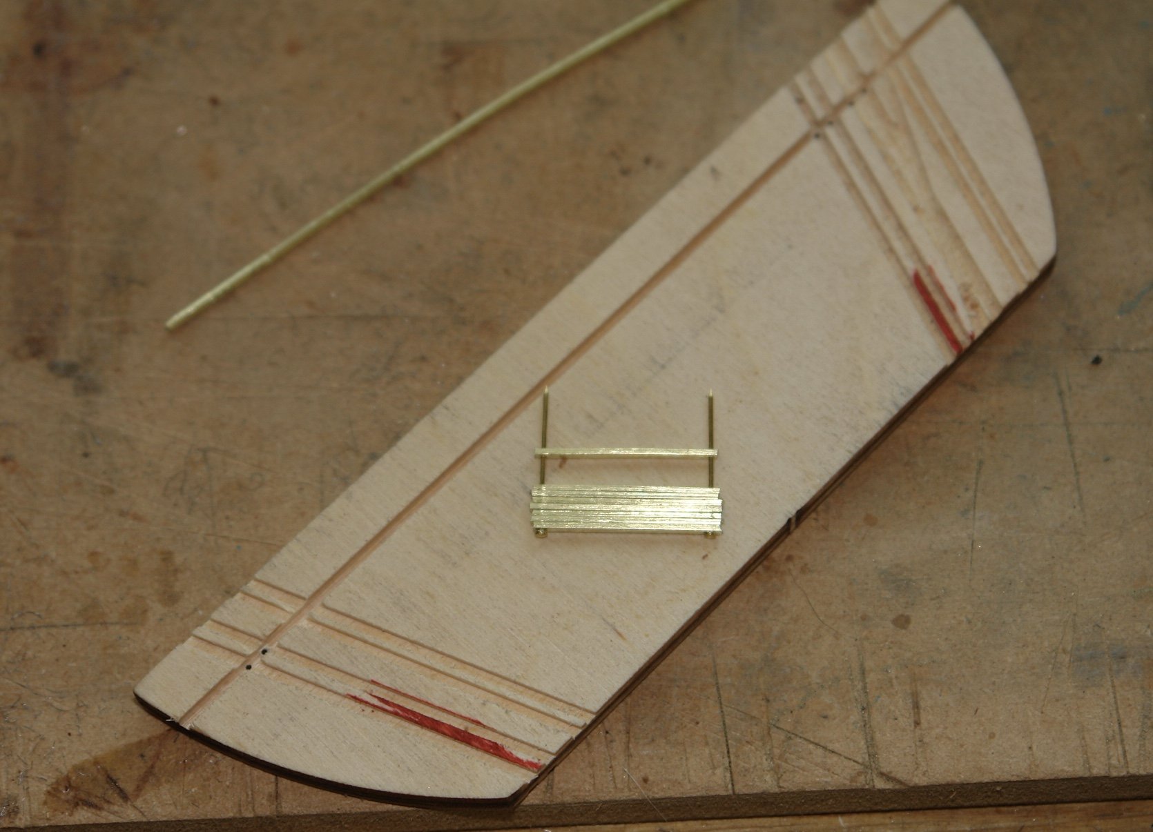
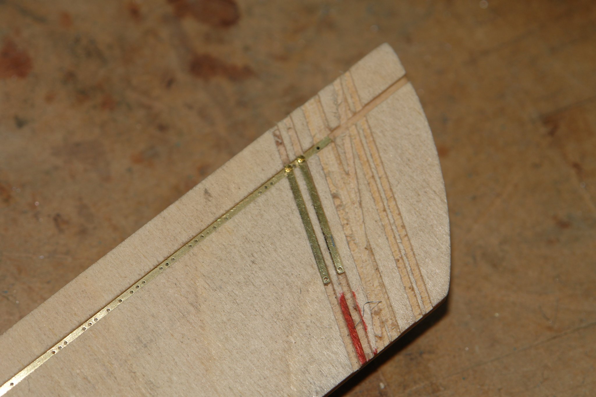
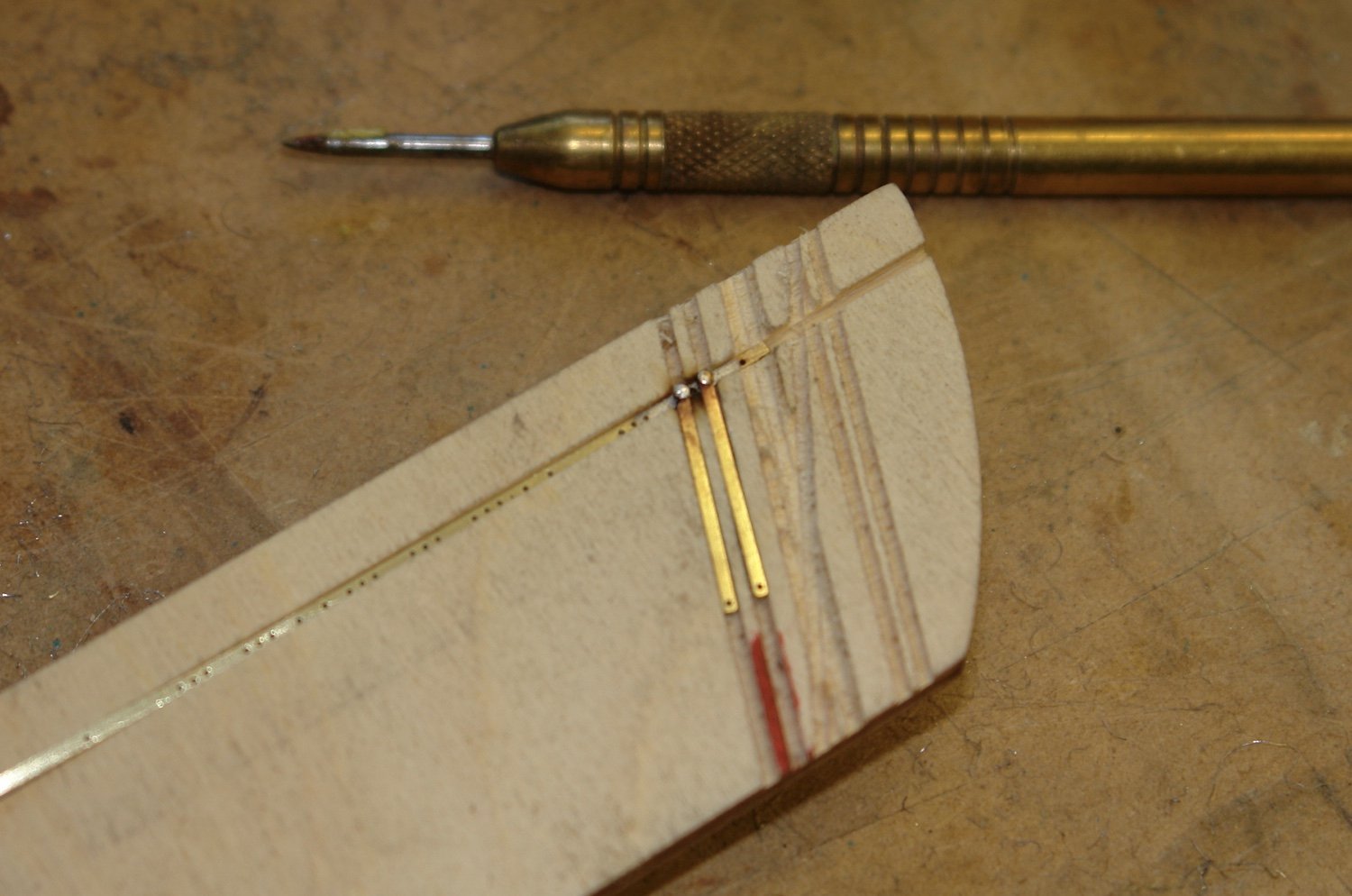
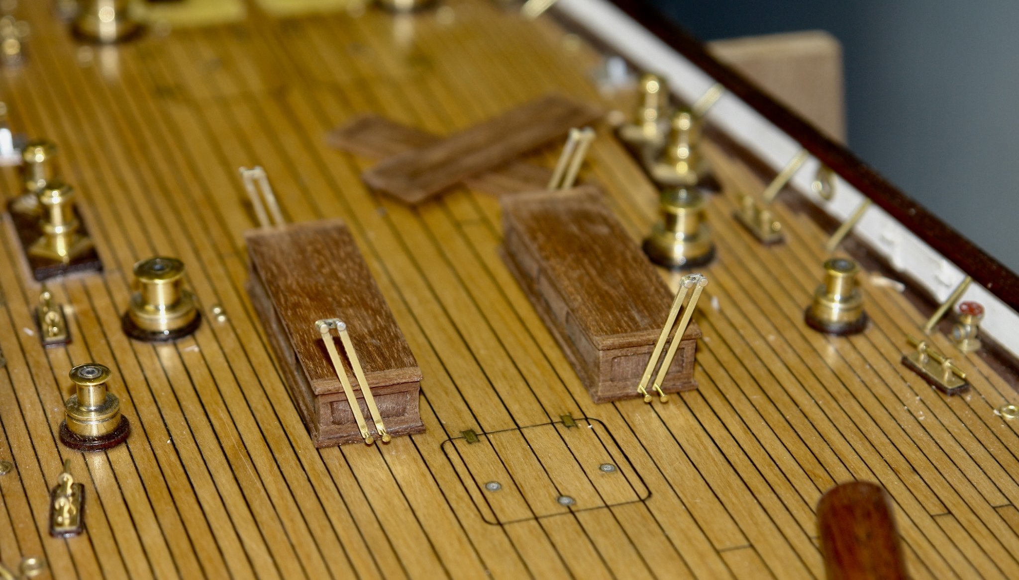
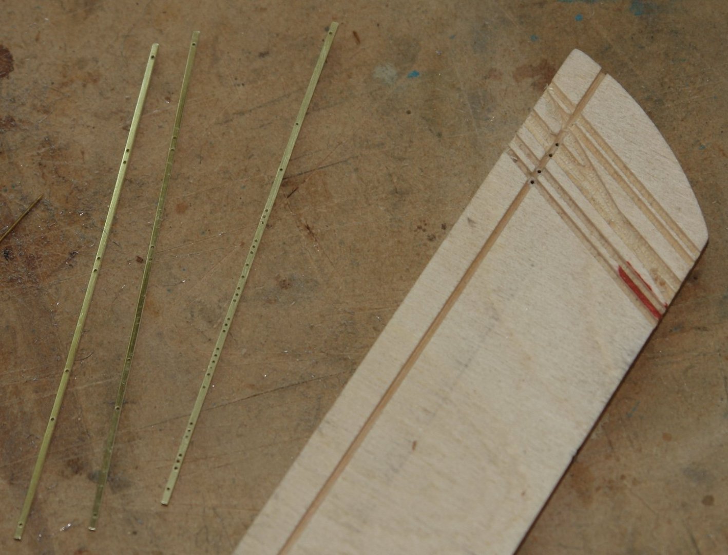
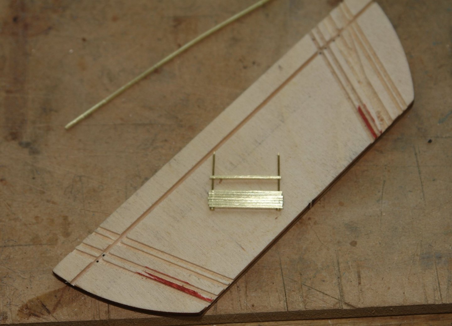
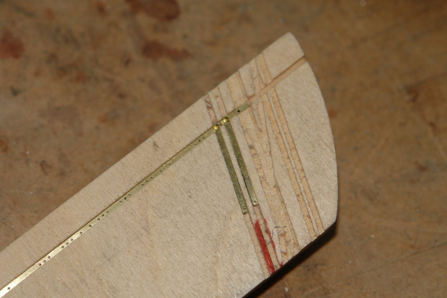
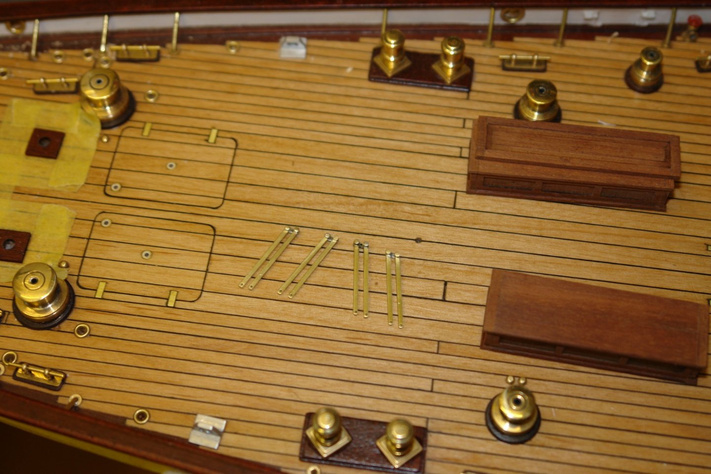
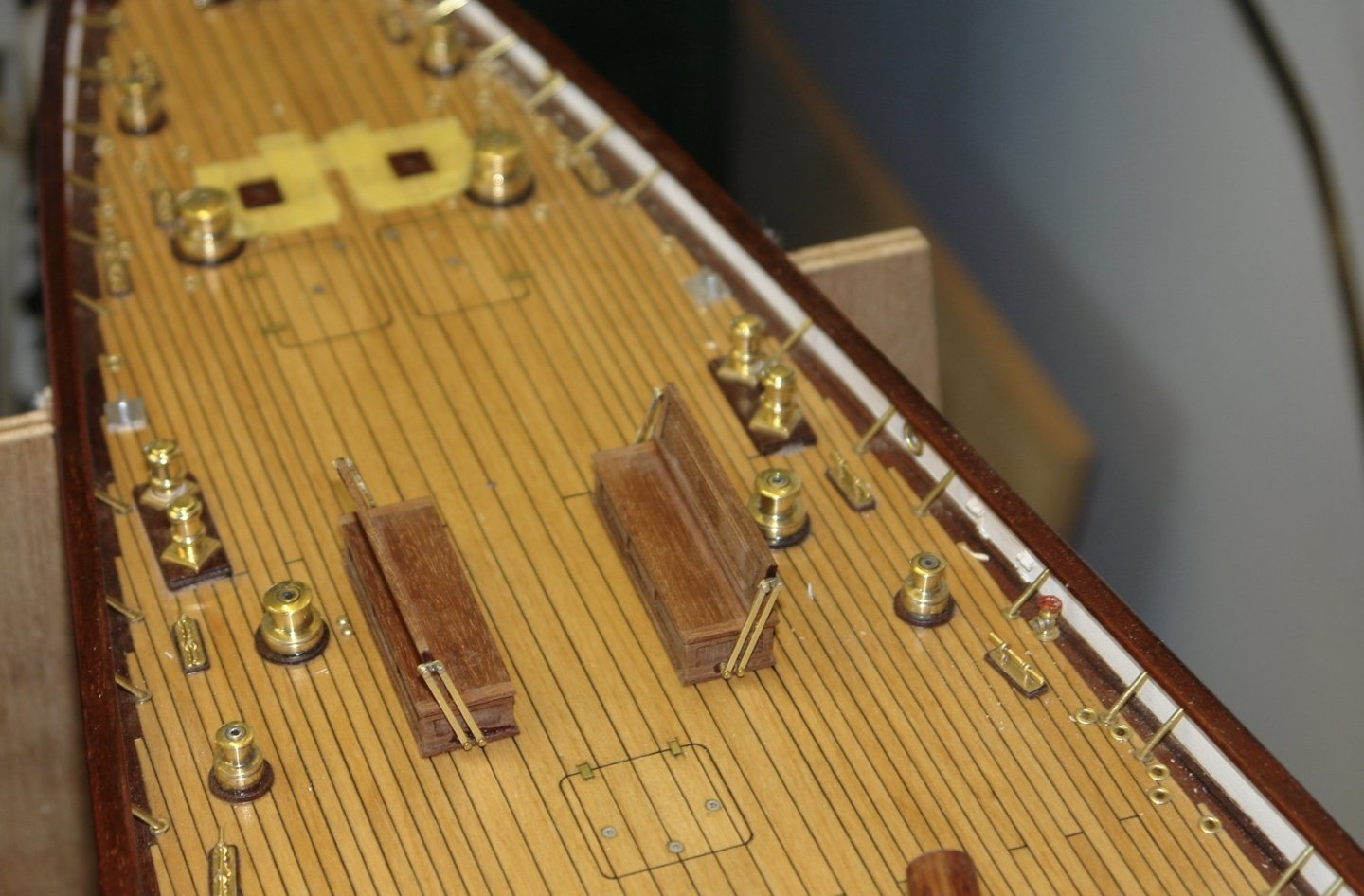
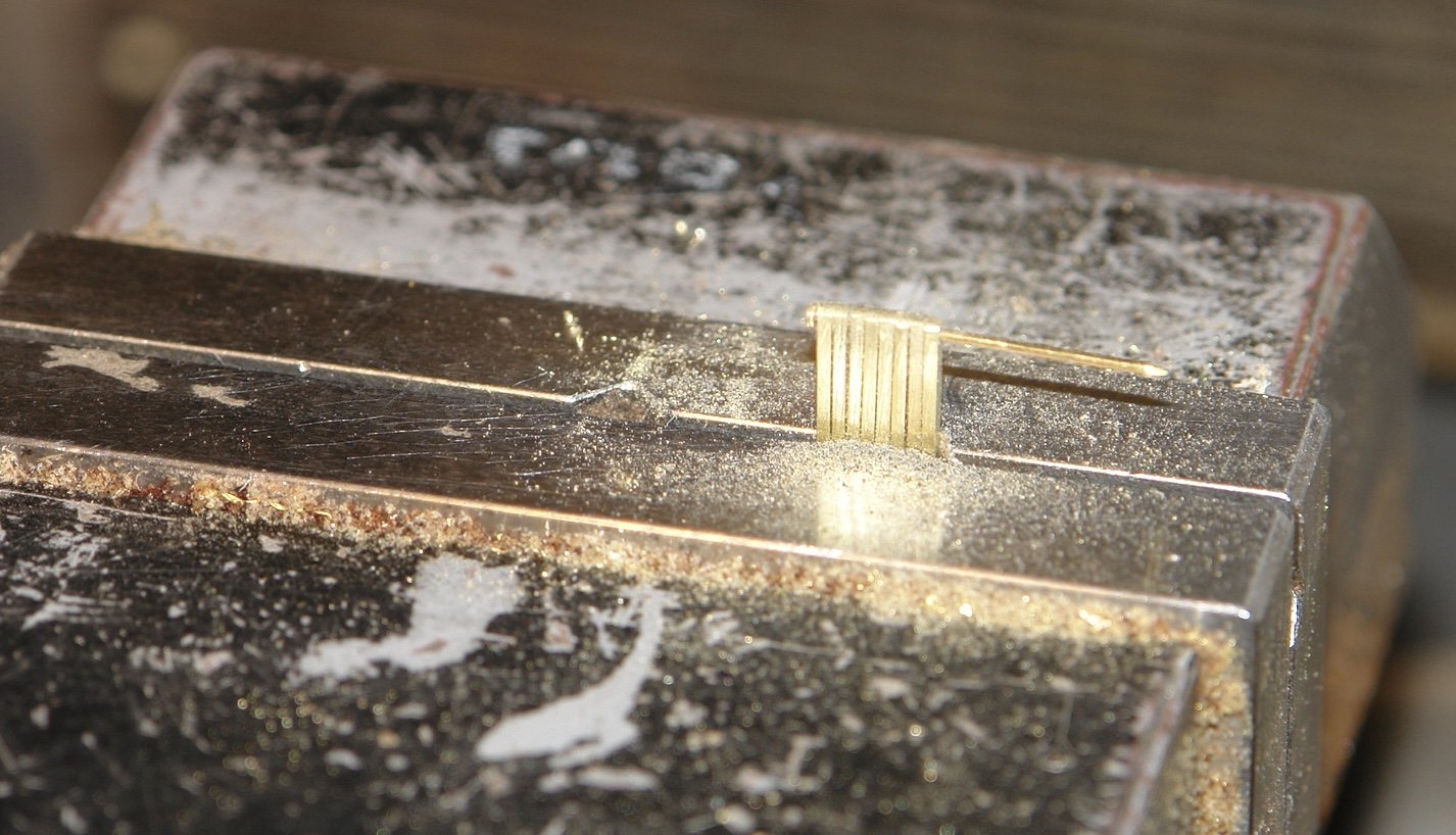
Thank you Keith. I finished off the benches starting with the hinge bars. I judged the size on these from photos and made them of .055" x .031" cross section brass. Strips were slit off from .031" brass sheet and then drilled with .025" holes. The 8 longer pieces were then cut down to length and slipped over a pair of sewing pins. Aligned in this way the bars were filed to length and the ends were rounded. I slit a series of slots in a piece of ply to create a rudimentary jig. I cut a number of slots until I was happy with the geometry. Brass pins were inserted at the intersections and then then junctions were soldered. The hinge bars were then cleaned up. The bench seats were drilled to take the lower ends of hinge bars. A piece of poly card was cut to position the back of the seat and attached with double sided tape. With this in place the backs were located in place and drilled to tape the upper pin. The backs were then glued in place.


-
A very interesting subject Brian. It will be a pleasure to see your progress. Good luck with the build.
-
All looking very neat. Yes very hot today, fortunately my workshop ( former garage) is north facing and on days like today is the coolest place in the house. Bad in winter but good in summer.
-
Hello Shipman - sometimes I take the easy way out. In this instance trying to inset them seemed a step too far. I console myself that different designs exist and in some instances the band is on the surface:- Thank you Keith, Kevin, Boris, Eberhard - but as Shipman righty points out - plenty of room for improvement.

-
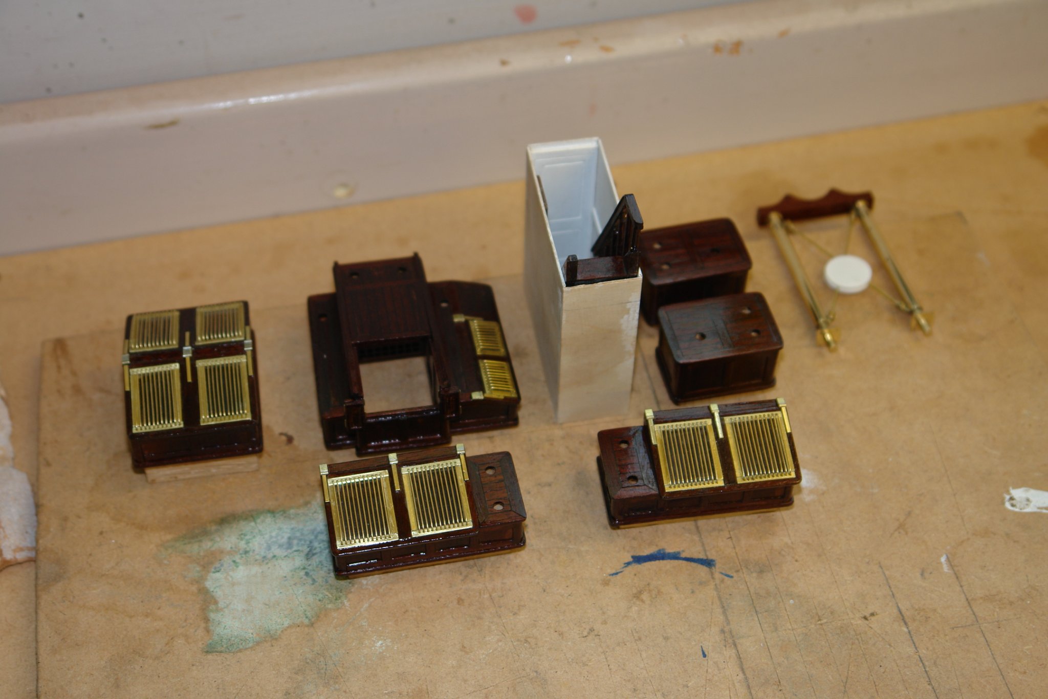
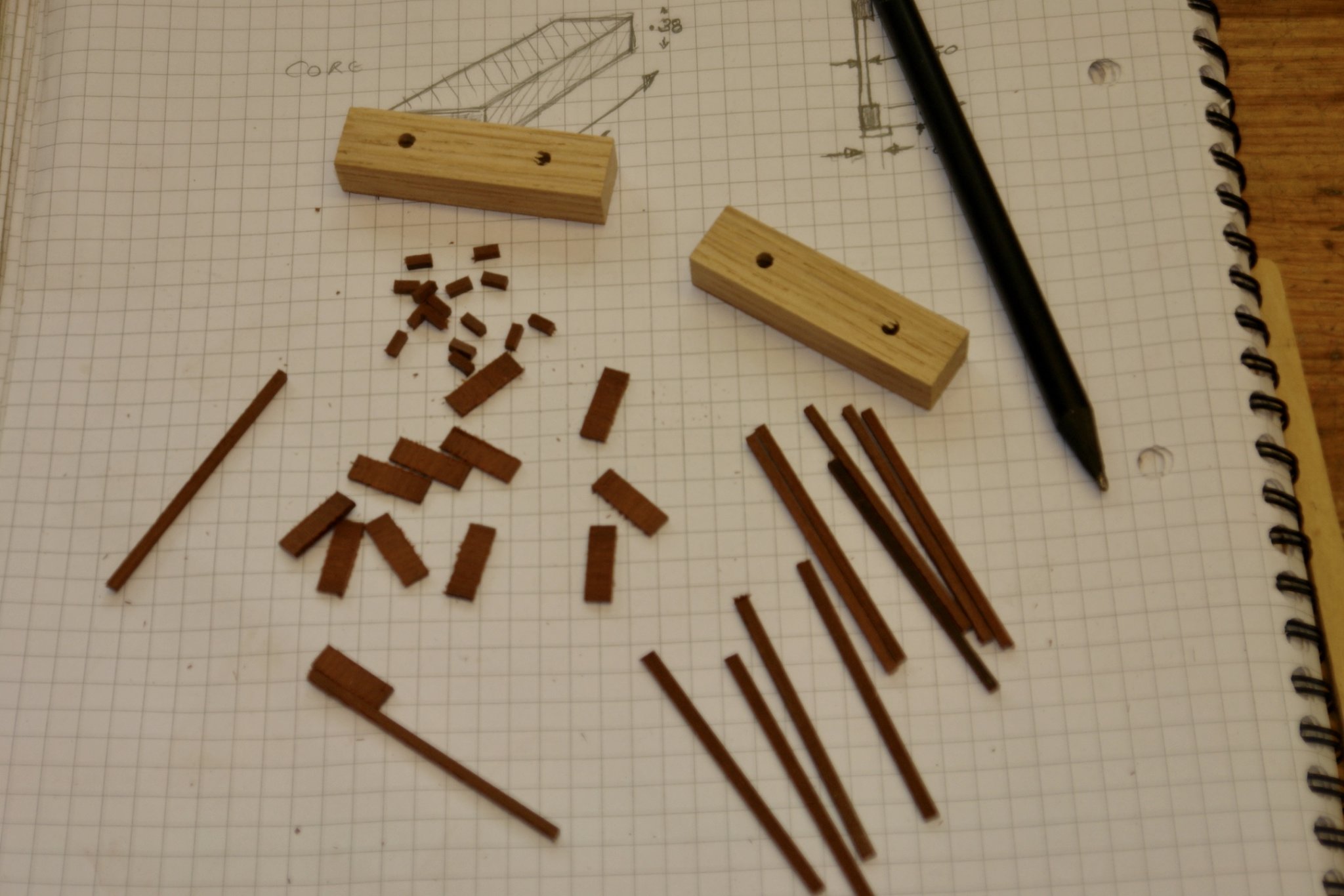
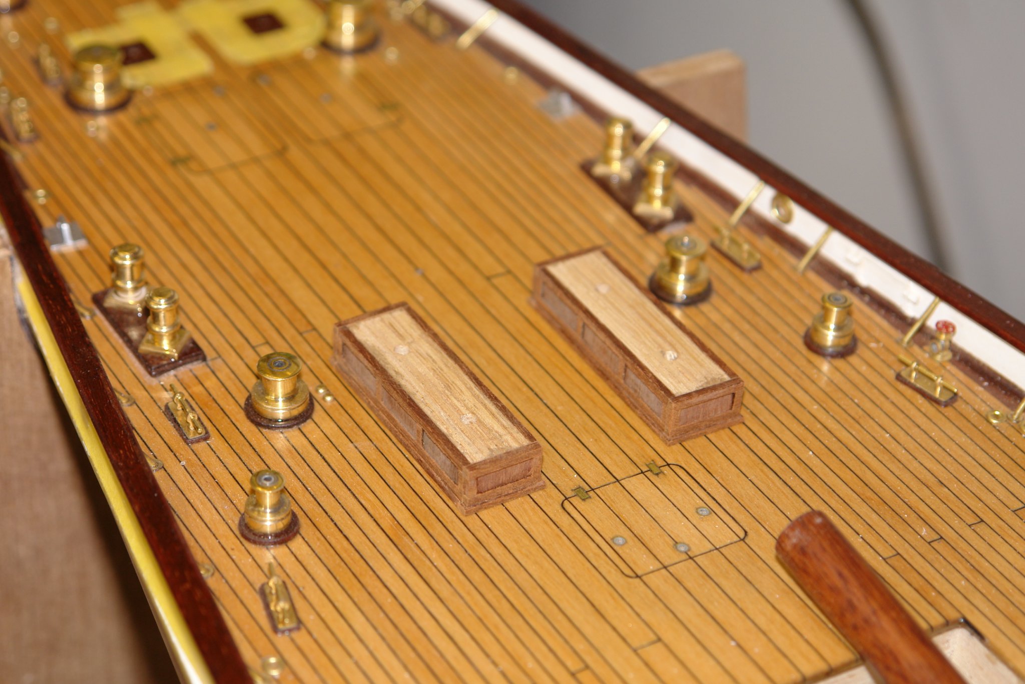
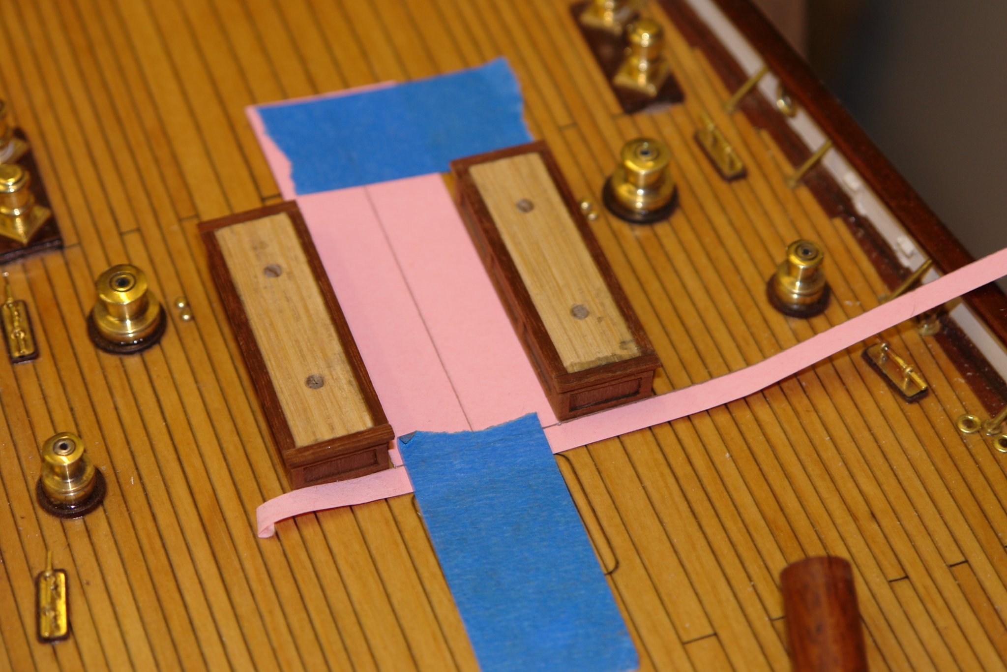
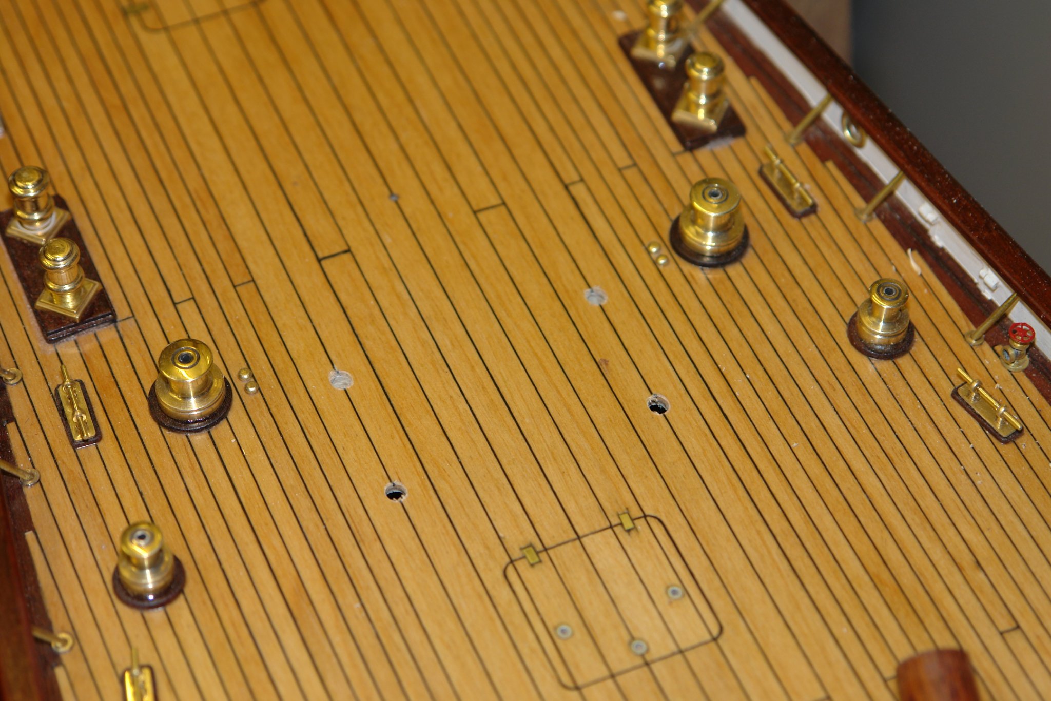
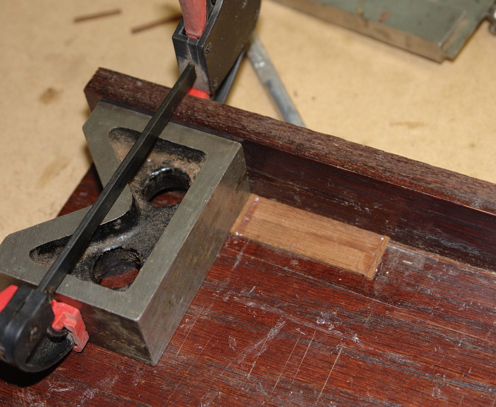
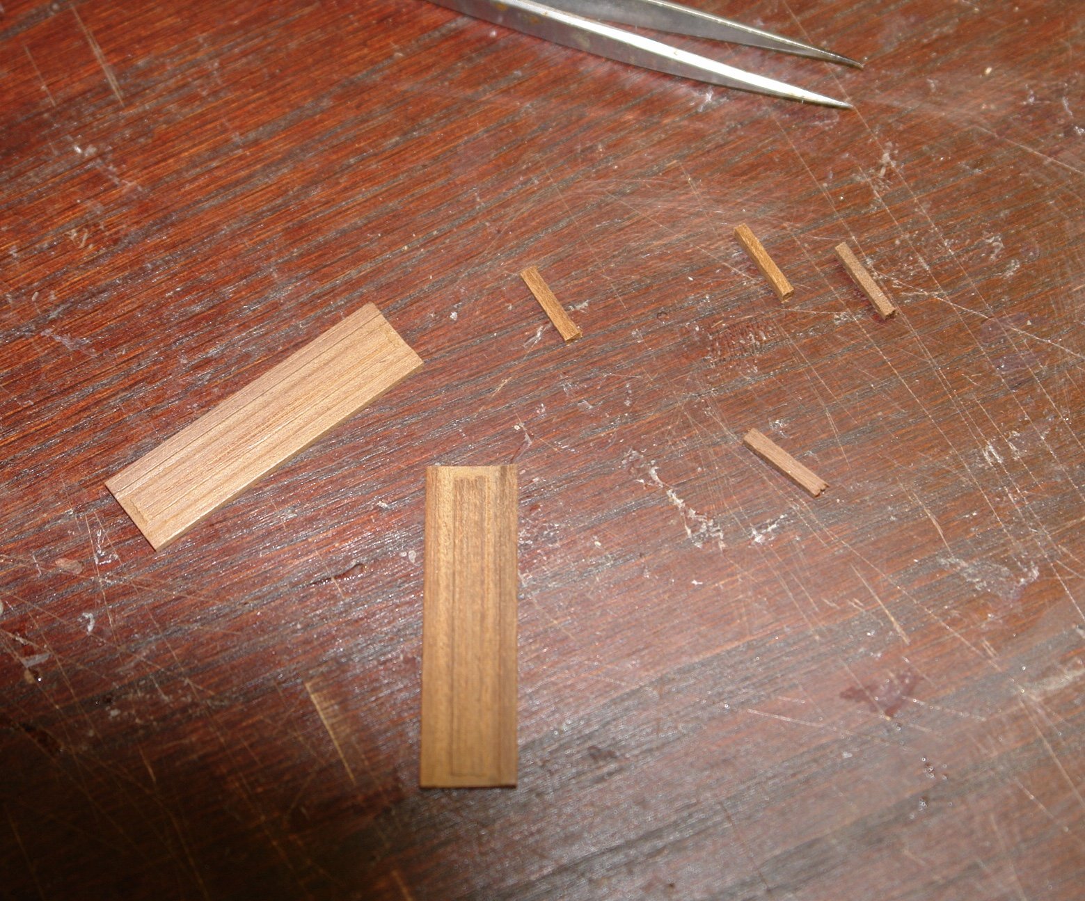
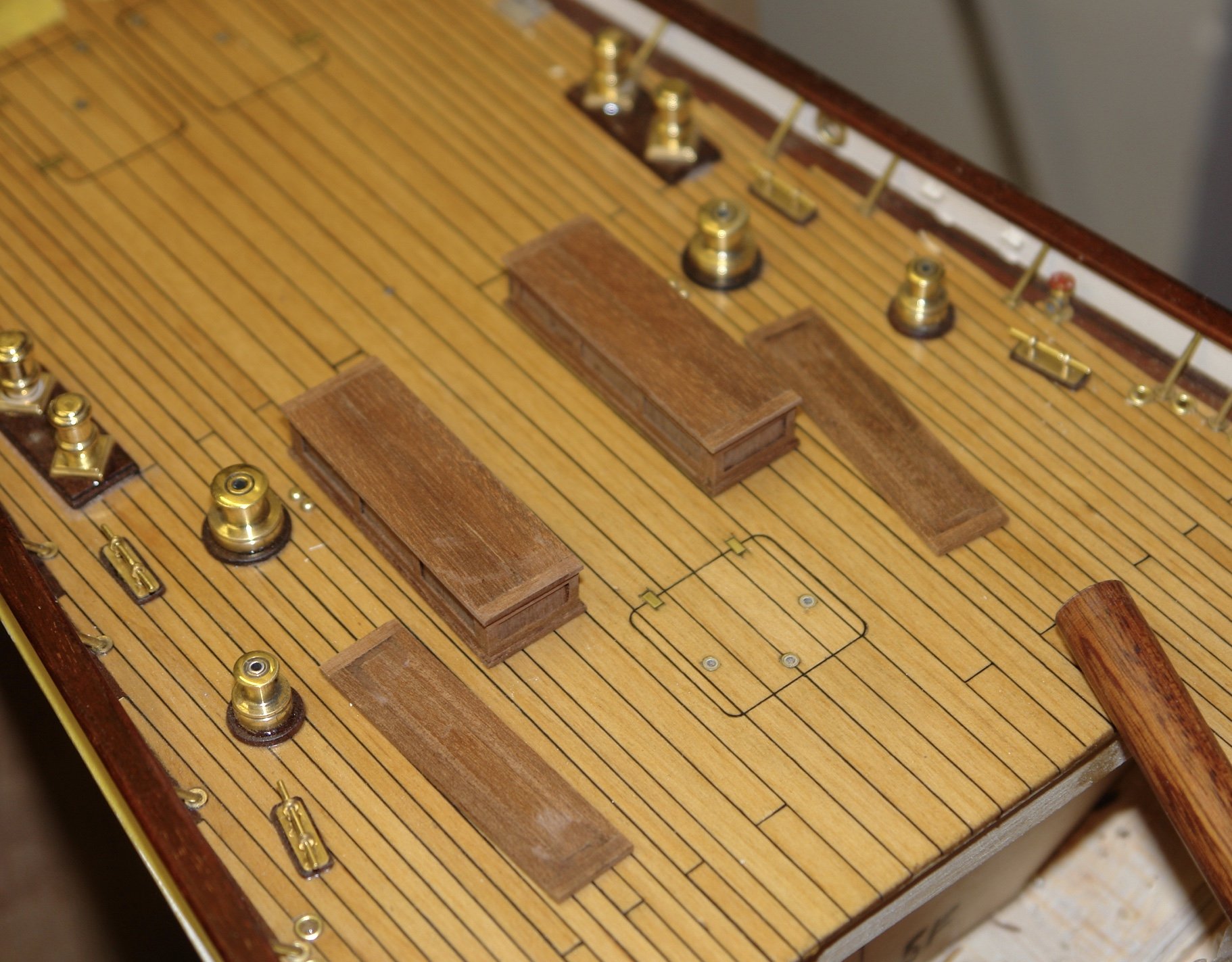
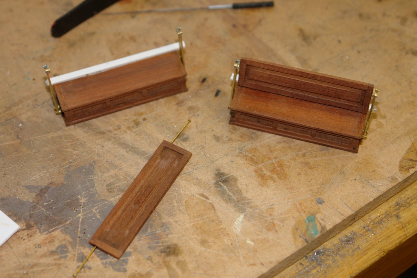
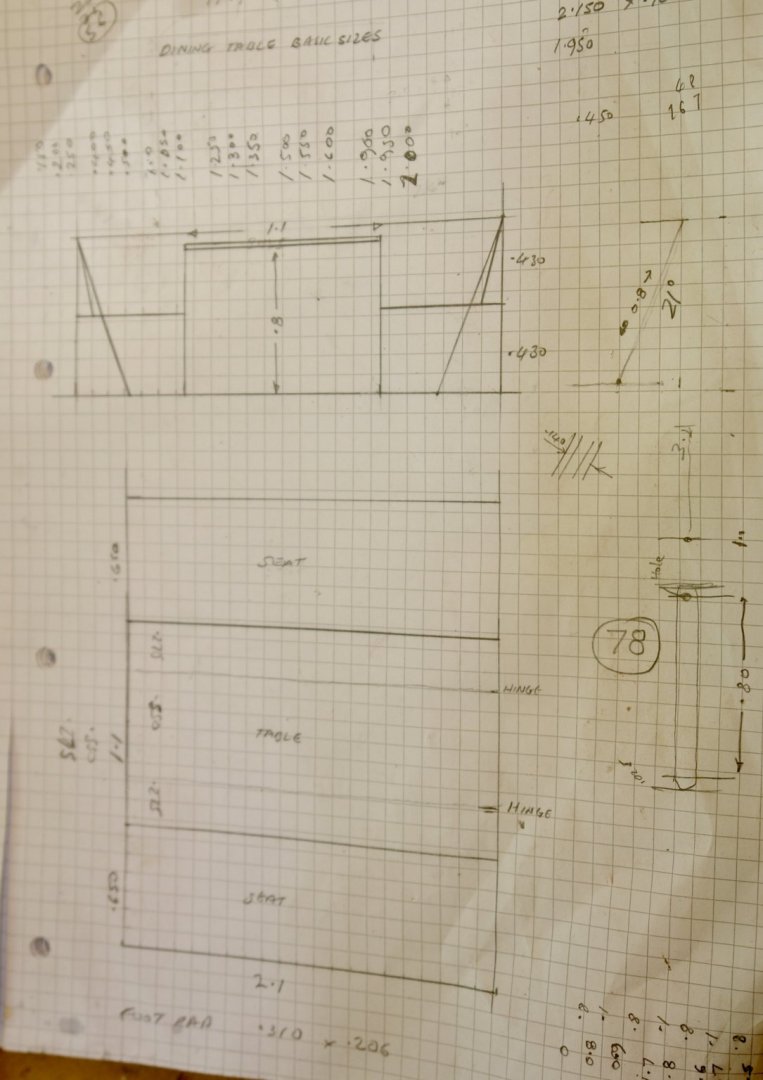
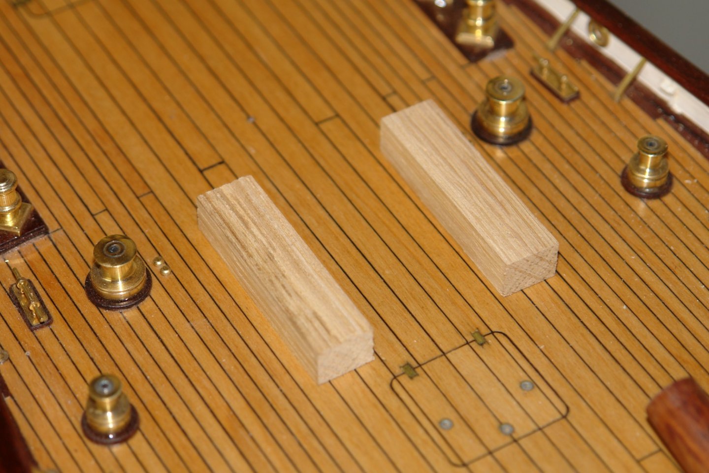
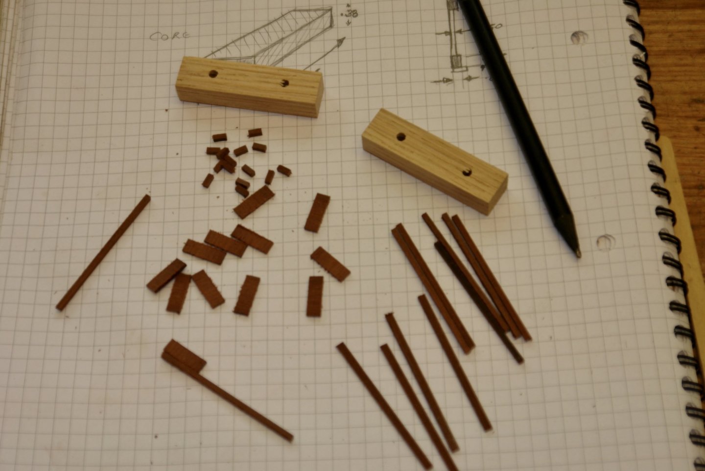
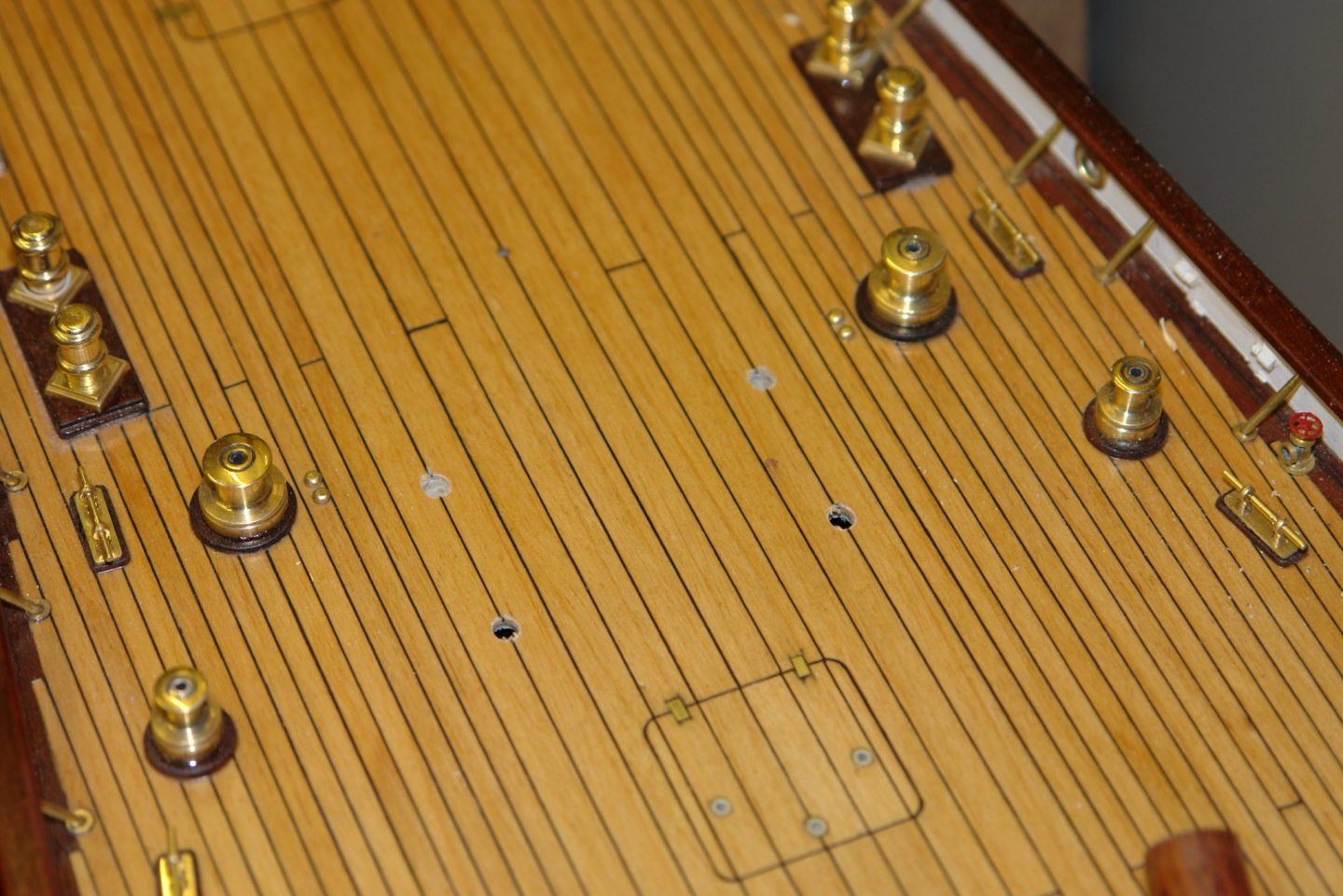
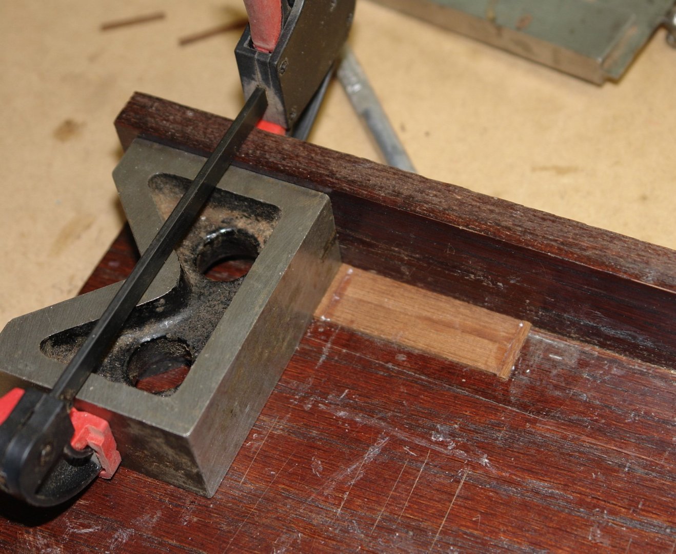
Pat, Roger, Richard - thank you for the comments. Also thanks to everyone the likes and visits. I gave the various deck houses a coat of Poly (the first of a number of coats). Then proceeded to the deck benches and table. The deck benches have hinged backs (trolley bus style) so they can face either out or in. Mine wont be operable and will face inwards. The most distinctive feature is the pivot bars and I will try to do a reasonable reproduction of these. The sketch was pretty basic - predominantly focusing on the major dimensions. The bench seats are 2.1" long x .650" wide x .430" high to the seat and .860" hight to the top of the back. The hinge bars will be .055" wide x .03" thick. The bench seats were built on oak cores. All the cladding mahogany panel pieces were cut and the oak cores were drilled to take 1/8" location pegs The bench sides were clad. I used a card template to locate the benches in their correct position and then drilled through the location holes. The bench tops and backs were then made out of .060" thick planks. I now need to get on with the hinge bars which will be a bit more of a fiddle.


-
Well Javier that seemed to take a little under 2 weeks. Amazing.