HOLIDAY DONATION DRIVE - SUPPORT MSW - DO YOUR PART TO KEEP THIS GREAT FORUM GOING! (Only 44 donations so far out of 49,000 members - C'mon guys!)
×


KeithAug
-
Posts
3,957 -
Joined
-
Last visited
Content Type
Profiles
Forums
Gallery
Events
Everything posted by KeithAug
-
 Paul - Michael is correct and bobbin and button both seem to be used. Ideally they should be left loose on the shaft so they can rotate. Once you have filed down to the bobbin / button it rotates and the file rolls over it without cutting - hence you stop cutting the metal being filed.
 -
Bedford;- I recently bought a cheap (Chinese) ER11 collet chuck an collets on eBay. Not the best quality but adequate of modelling. I find them a very useful addition for small work in my medium sized lathe. The whole lot cost about £20. Lovely work on the rudder - I forgive the rope.
-
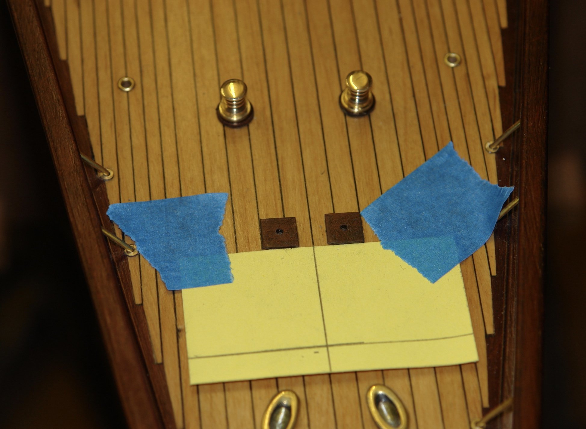
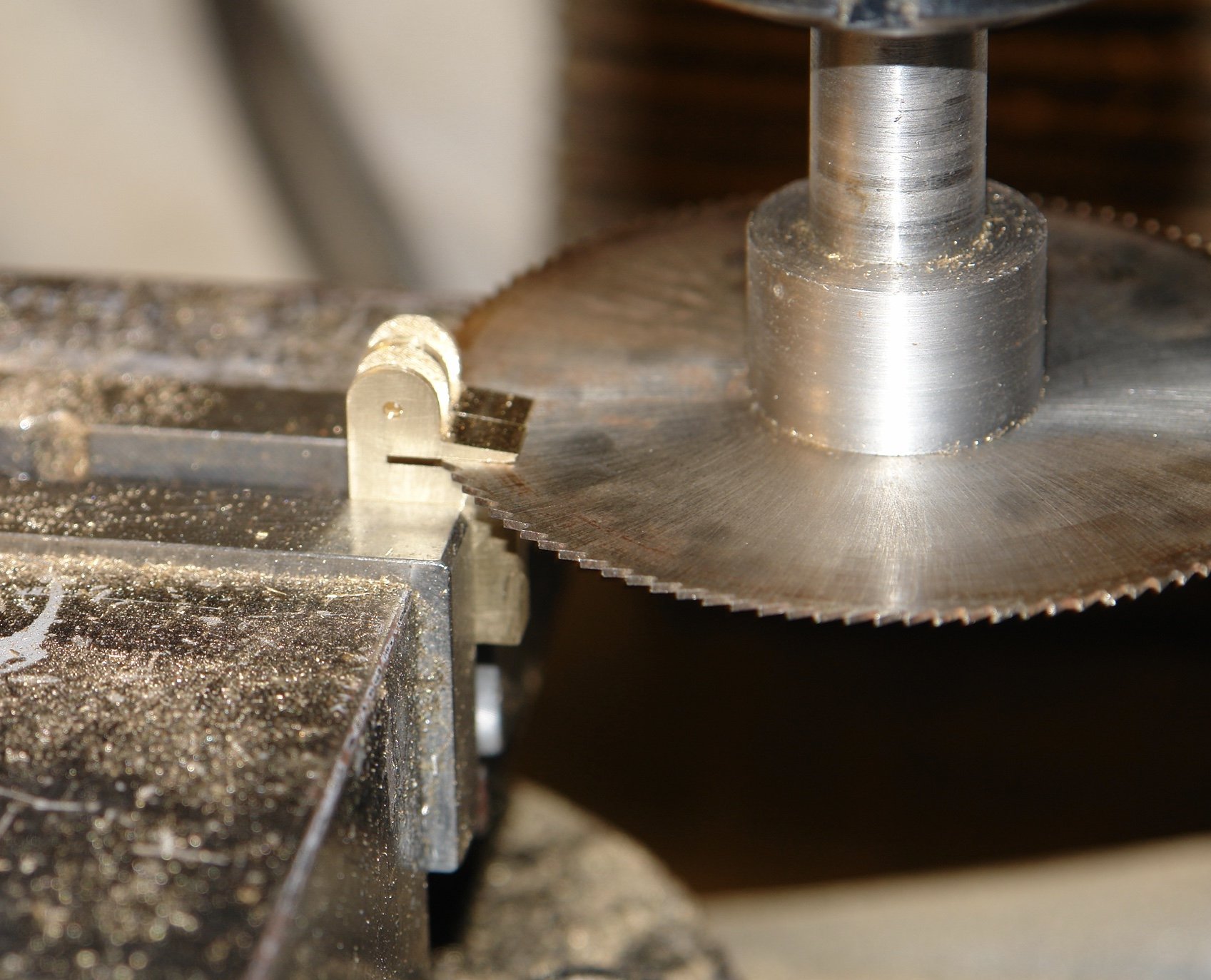
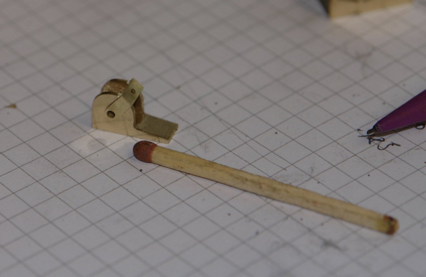
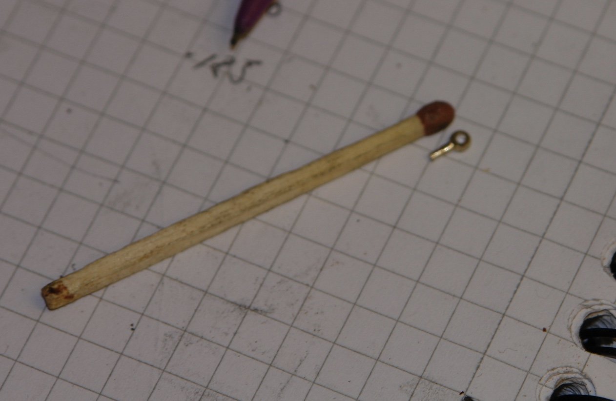
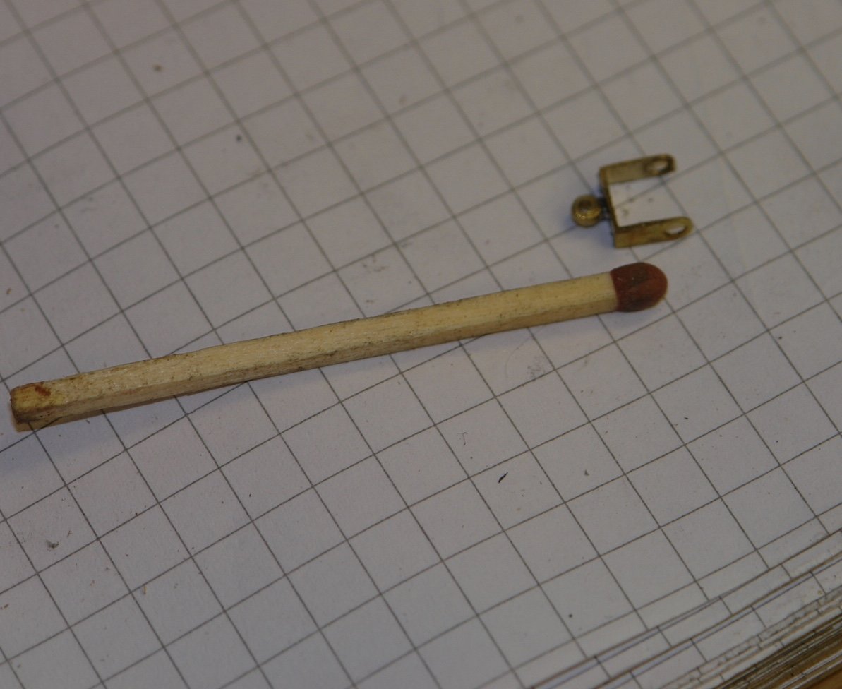
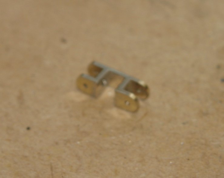
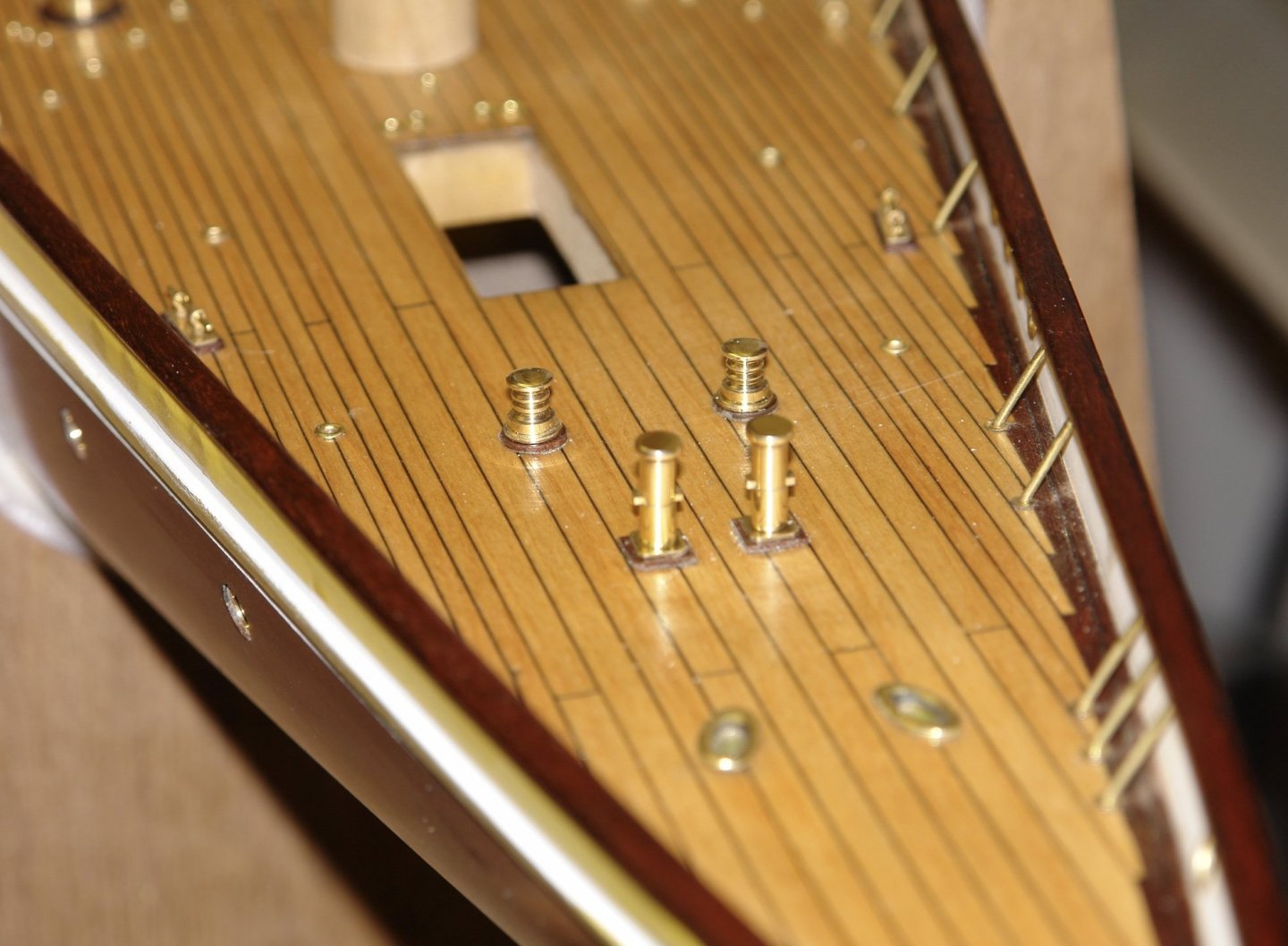
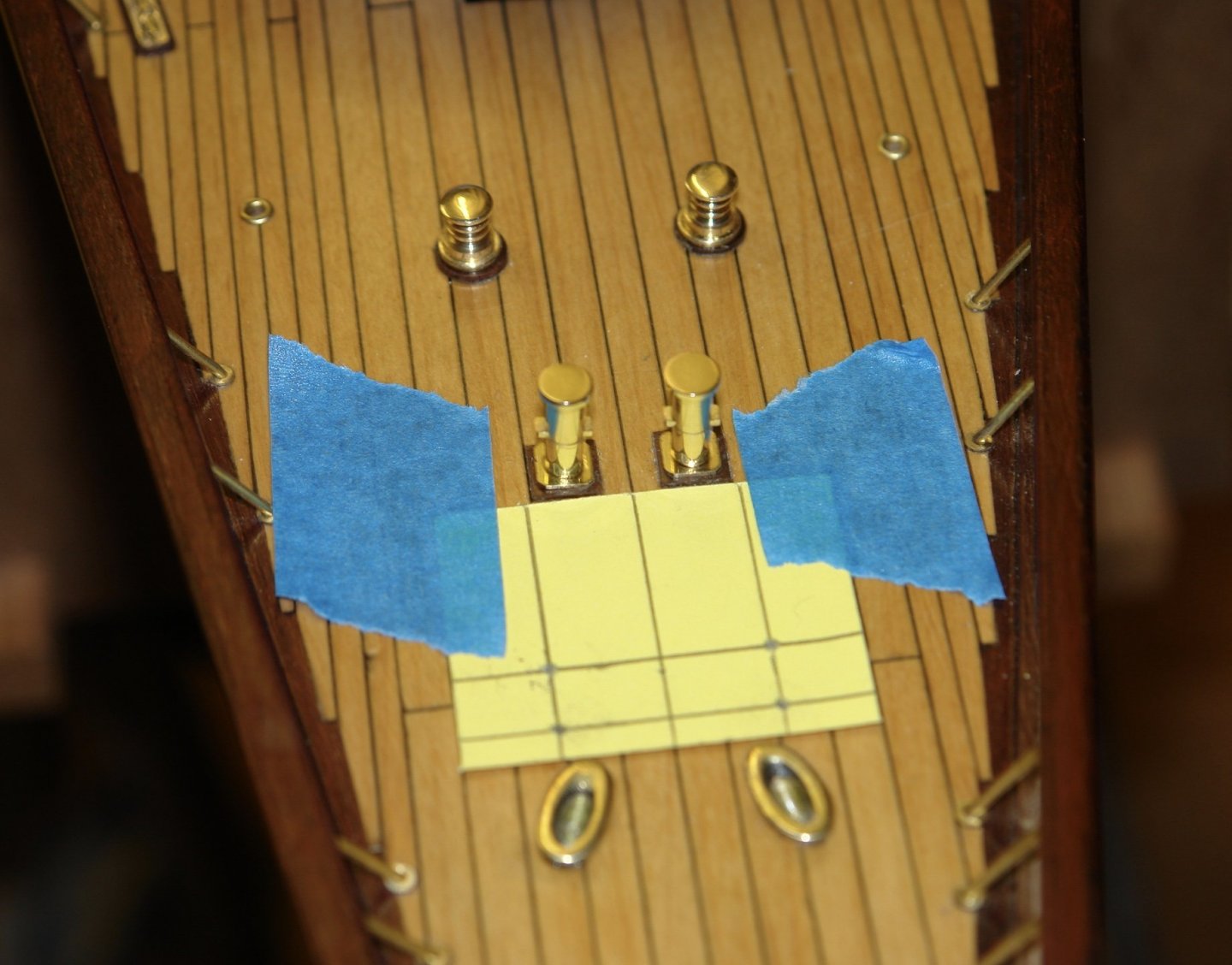
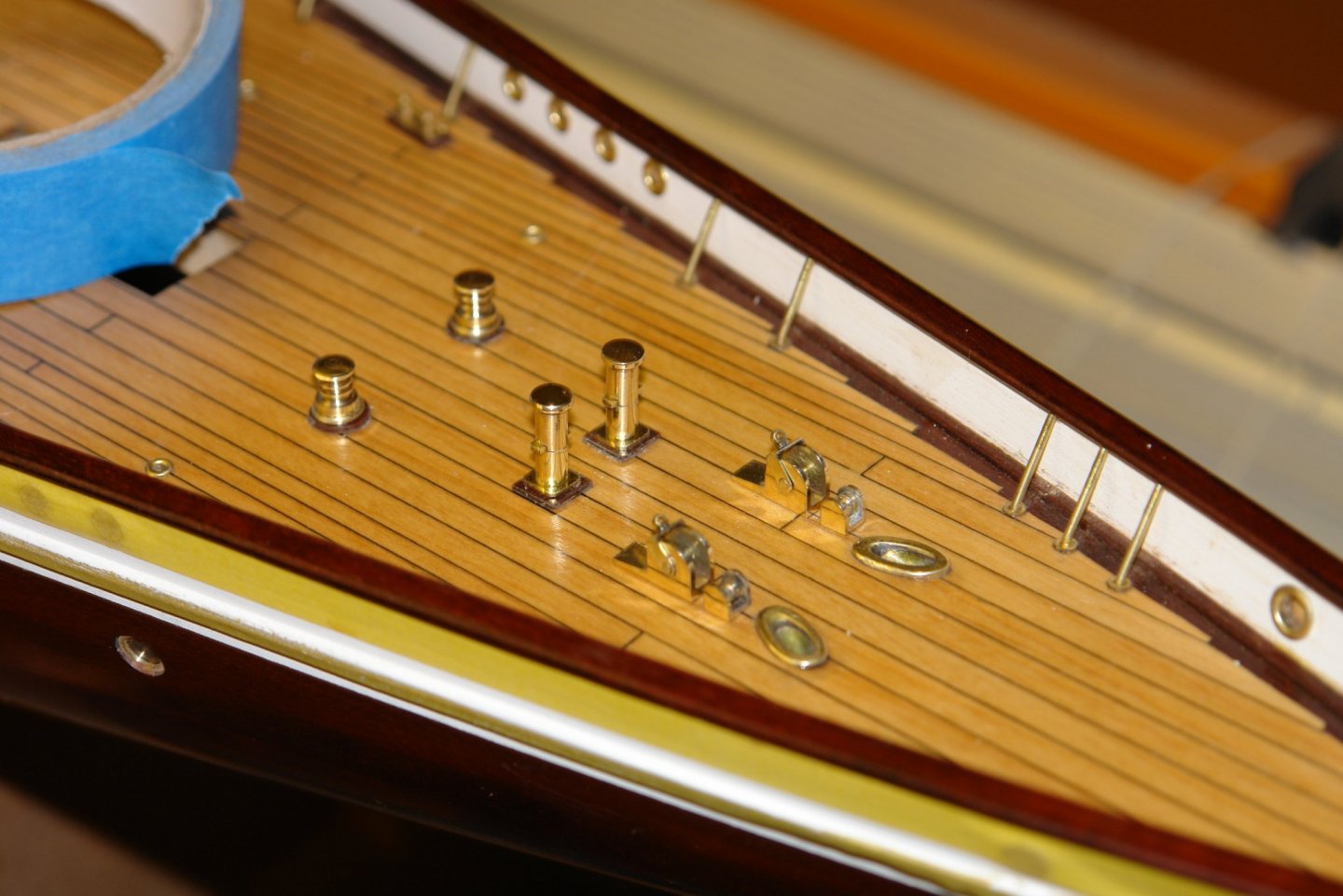
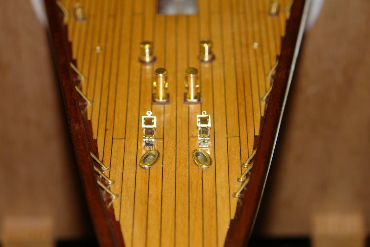
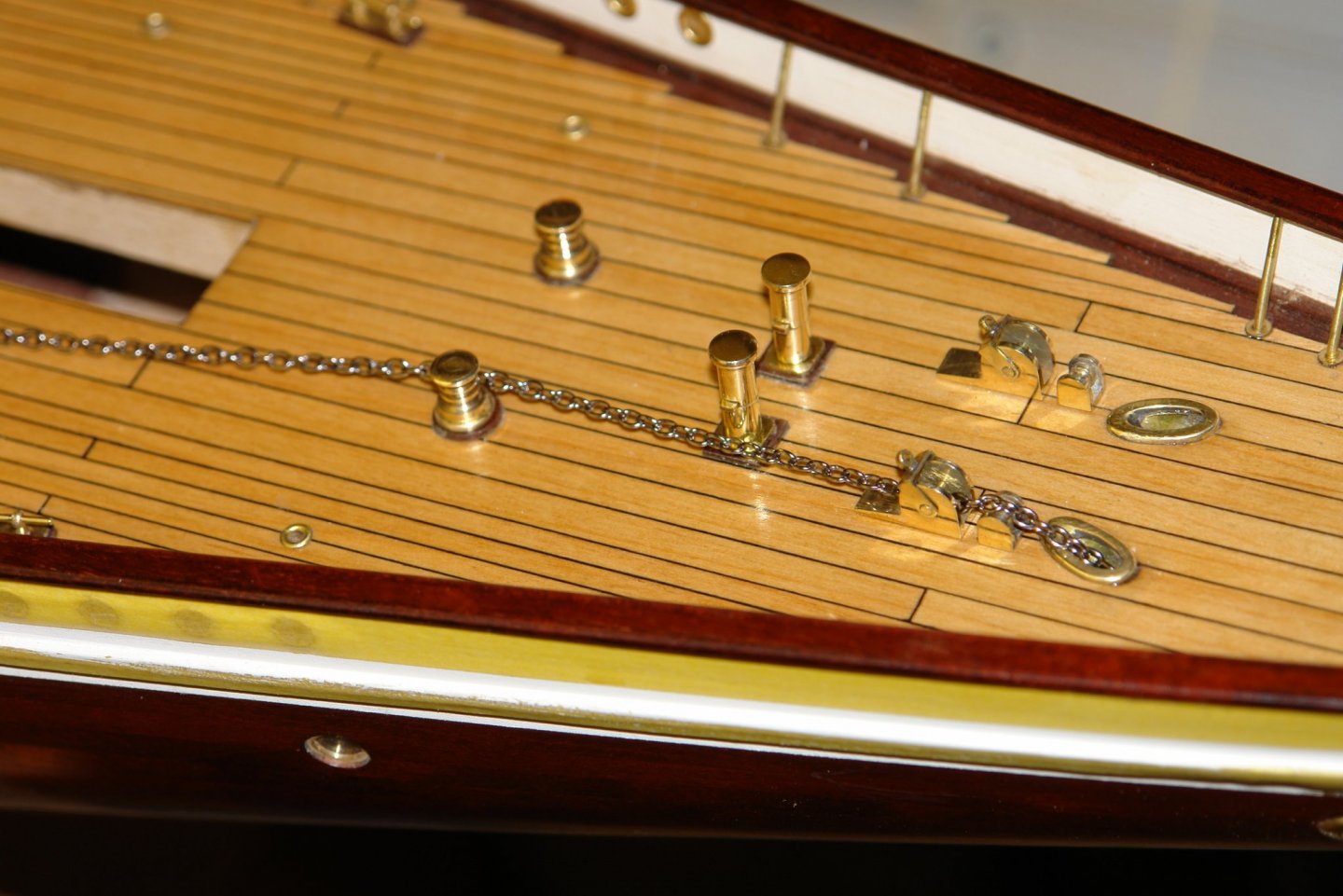
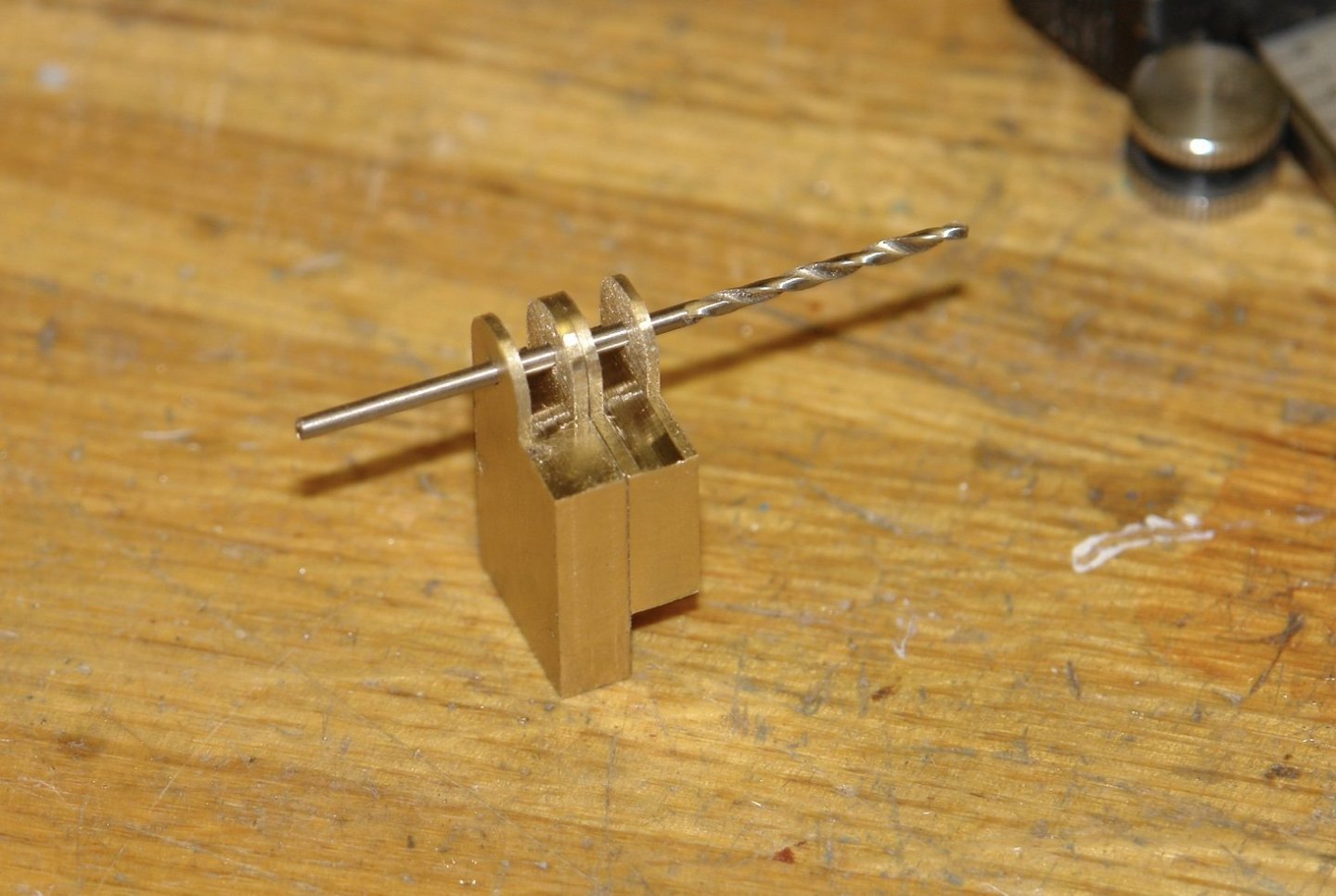
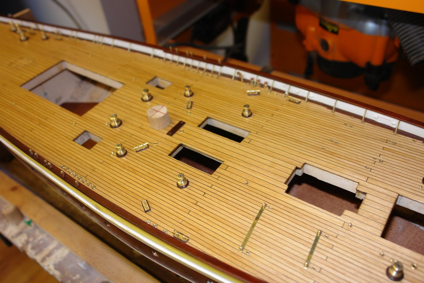
It is pretty miserable outside today but at least the workshop is sitting at a comfortable 9c (48f). I made the pawl handle from a scrap bit of square section tube .250" outside and .025" wall. I cut a piece of mahogany .2" square and glued it in the tube to provide strength while I machined it. I then drilled a 1/16" hole towards one end to create the pivot point for the handle. I then drilled a second hole in the side furthest away from the pivot holes to take the eyebolt. I then parted off the handle to the required width (0.1") on the Byrnes saw fitted with a slitting saw blade. I then hand filed the end with the hole to form the radius and remove the adjacent side. I then threw it away dissatisfied with the accuracy of my filing. I repeated this whole process a second time with the same result. I was taught many years ago how to file perfect radii but I had never tried it on such small parts (.05" radius). Anyway I made myself some filing bobbins from mild steel and did the job properly. I did a test fit on the pawl body and then went on to make the eyebolts (.09" diameter) as per the method previously described. The eyebolts were then soldered in place. While I was at it I soldered a location spigot on the base of the pawl body. Finally I cut some 1/16" rod for the pivot and assembled the parts. The small chain rollers were then made - not much explanation needed as the photos say it all. I then got on with fitting the various parts to the deck. The wooden plinths were made and positioned using card templates. The positions for the chain pawls were likewise located using a template. The pawls and chain rollers were then glued in place. Finally I found a bit of chain and tested the run. The chain is a bit large really. It has 11 links per inch and I think I will try something smaller before I commit.


-
Yep - wives have a habit of revealing our flaws, bless em.
-
Eberhard. I don't have any decent photographs of the area as it is very congested - lots of blocks and halyards obscure the view. The plans show reinforcing steelwork between the lugs and the deck - although not in enough detail for modelling. As it wont be visible I don't plan to reproduce.
-
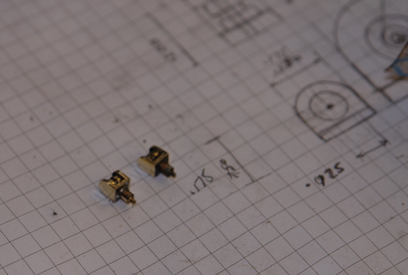
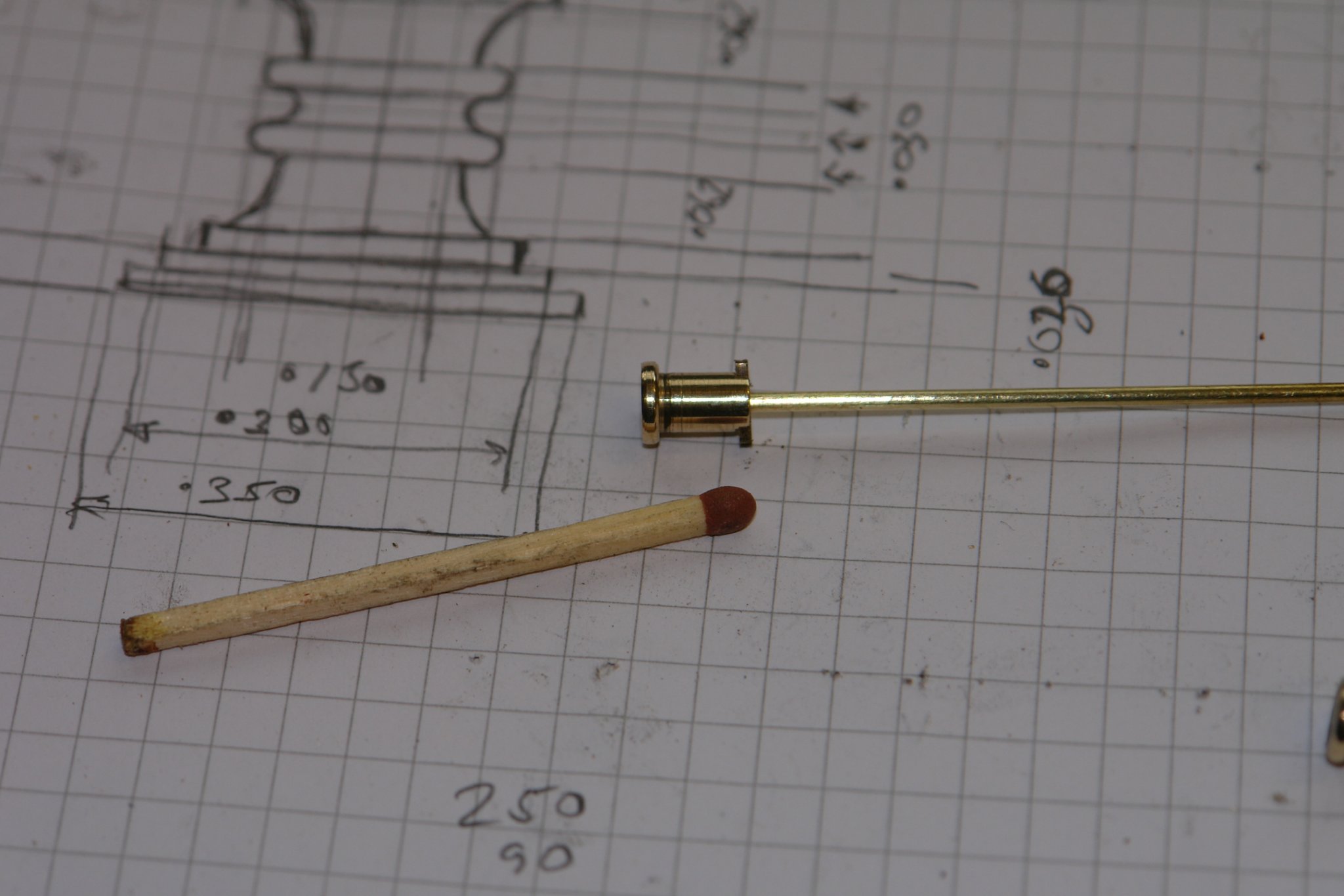
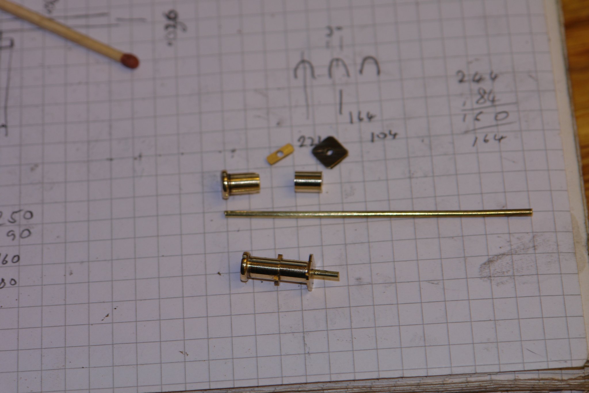
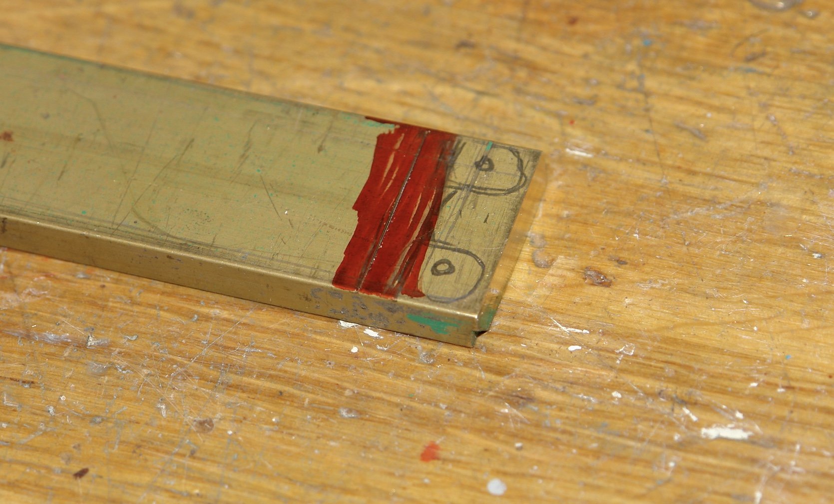
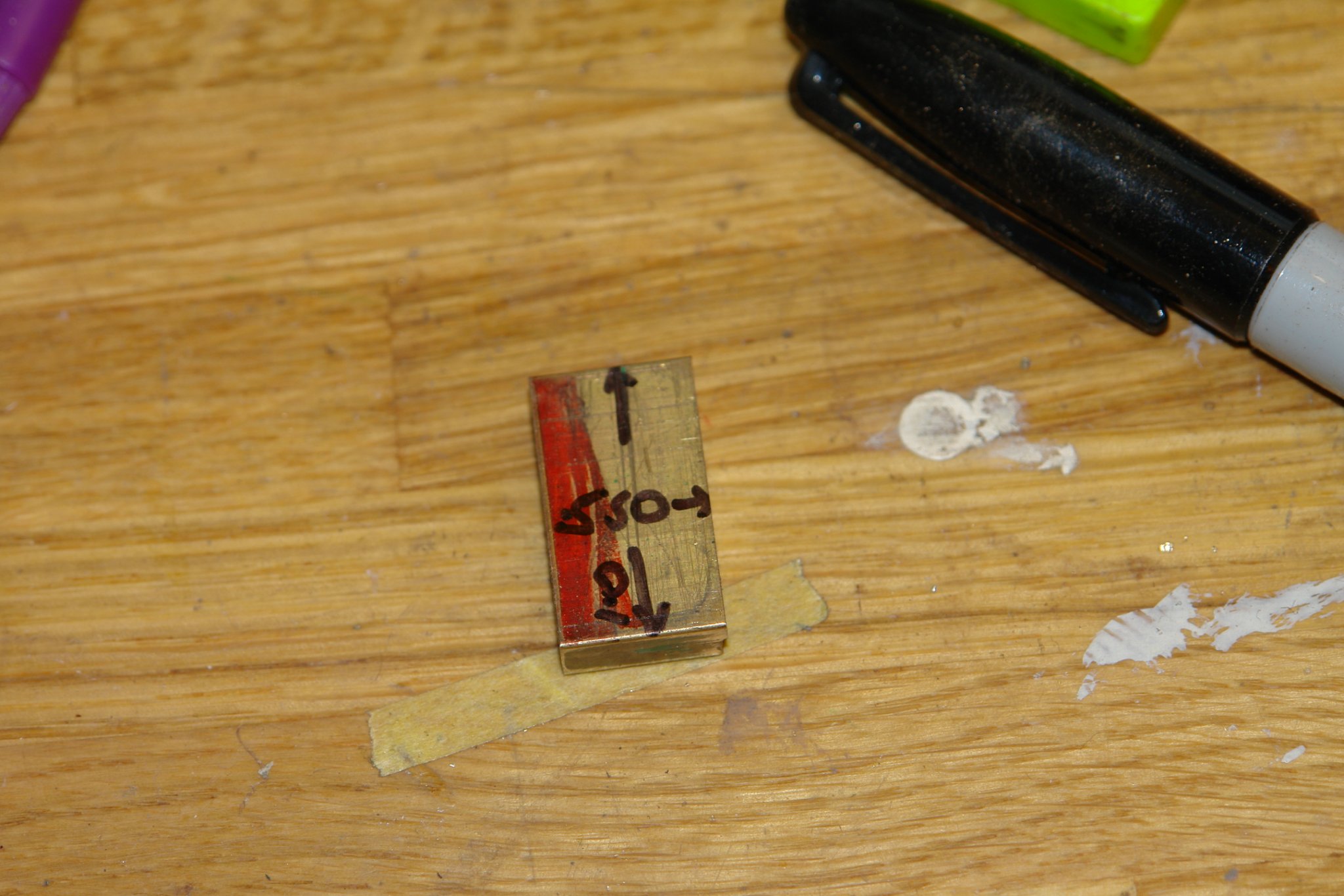
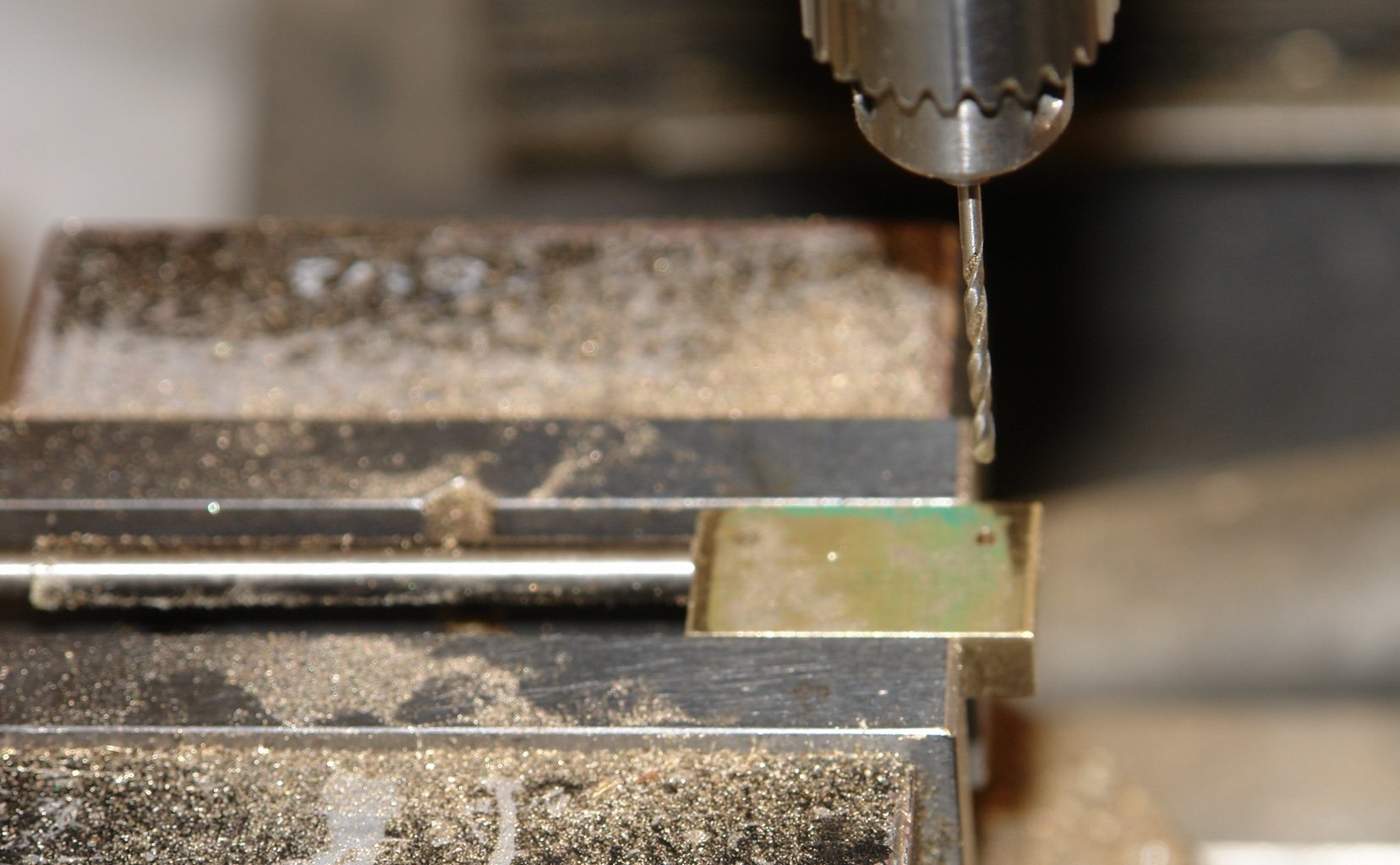
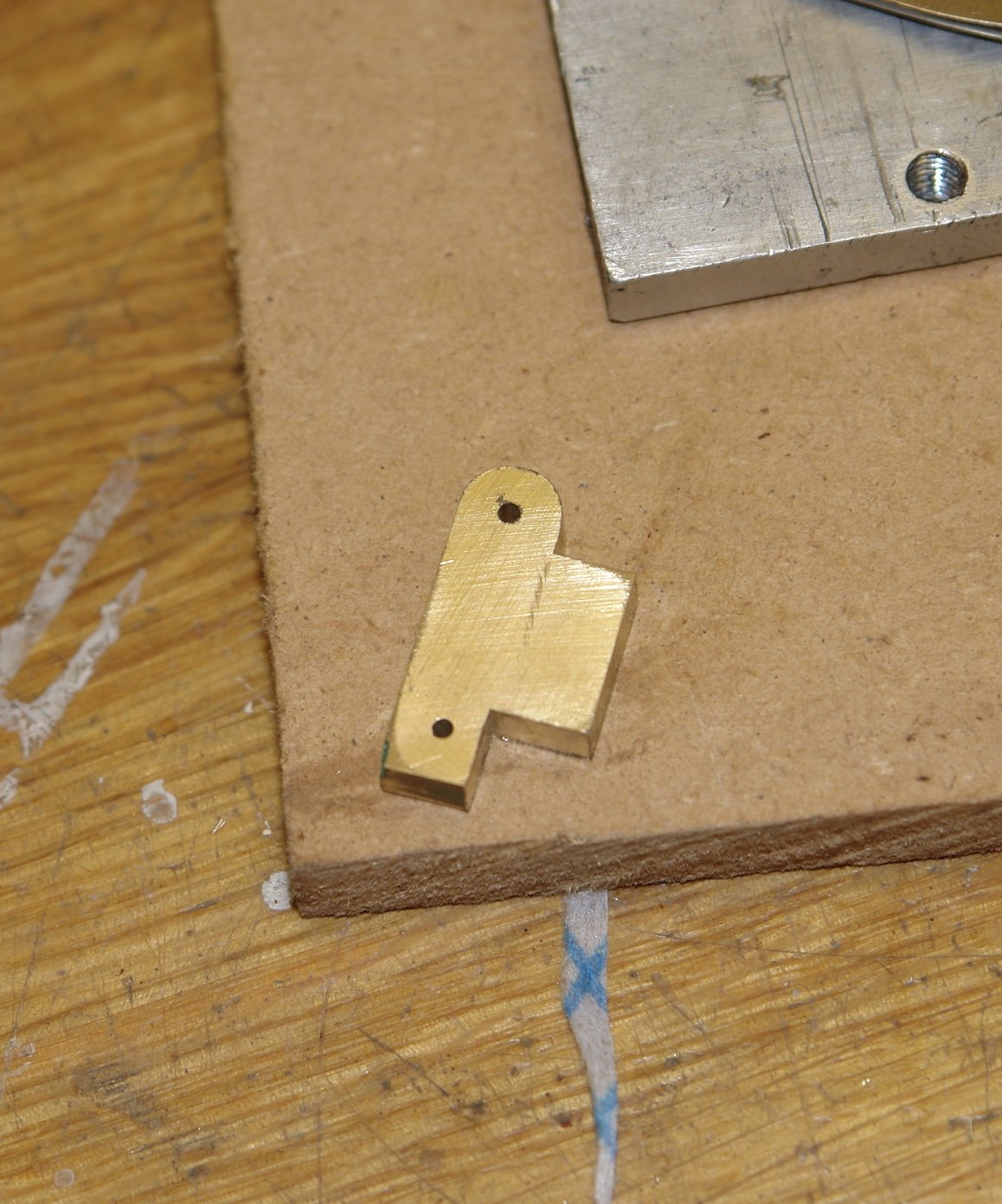
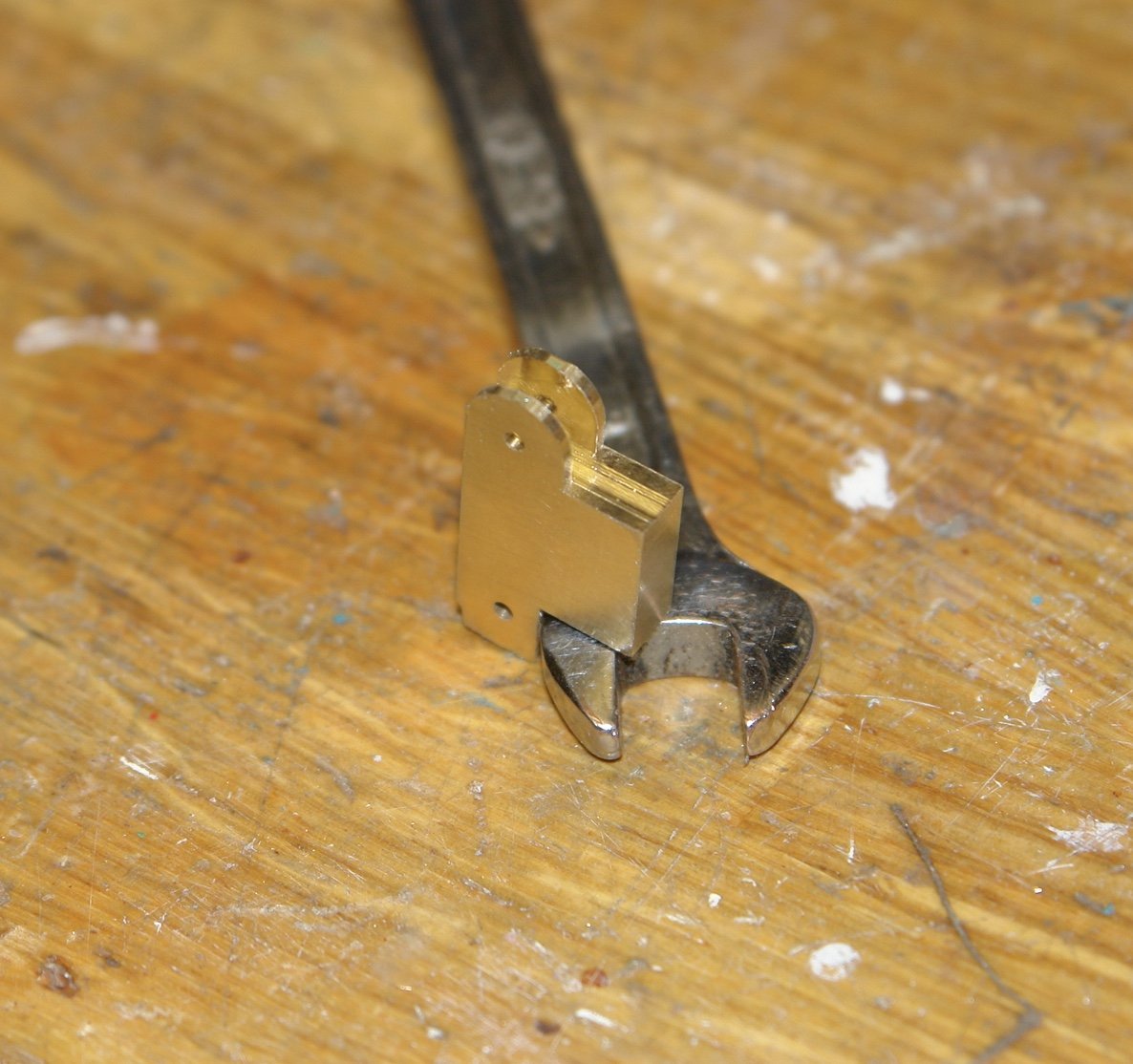
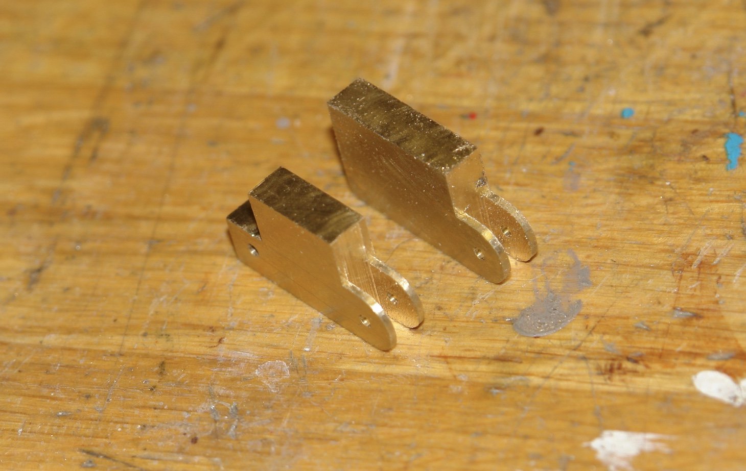
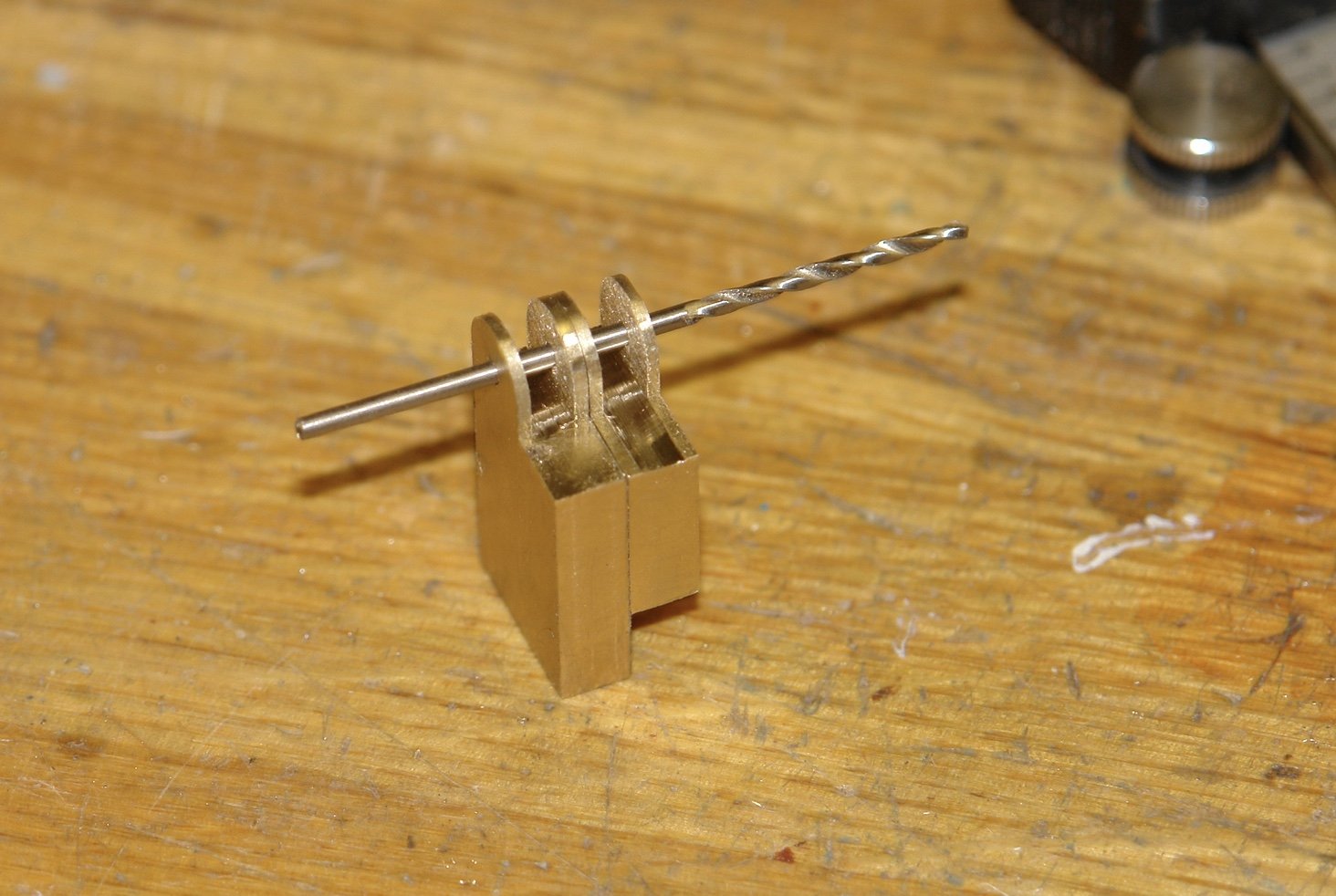
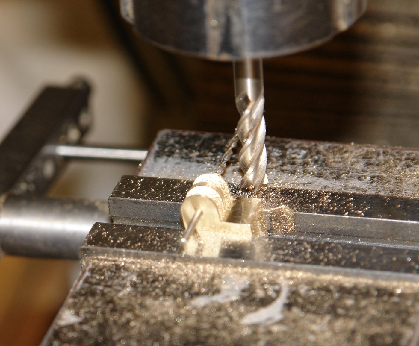
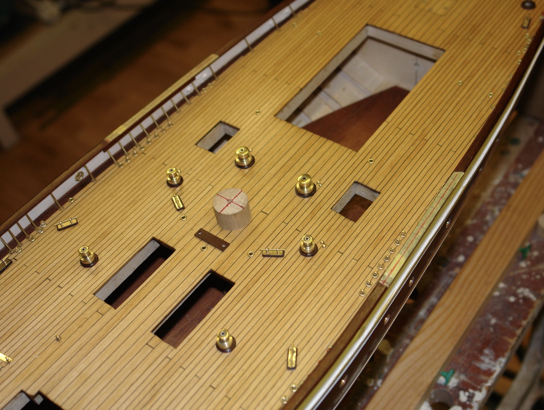
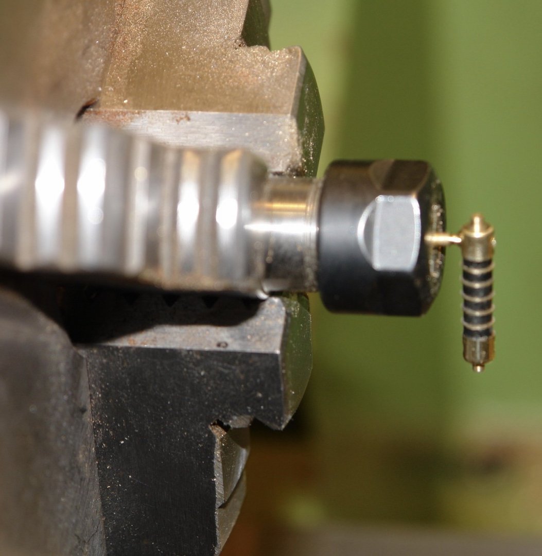
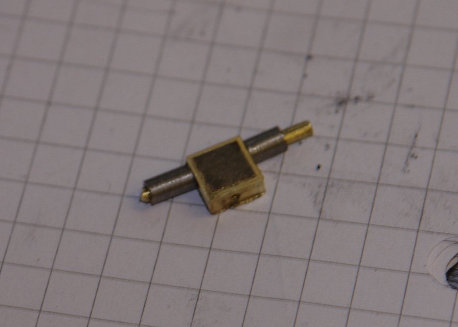
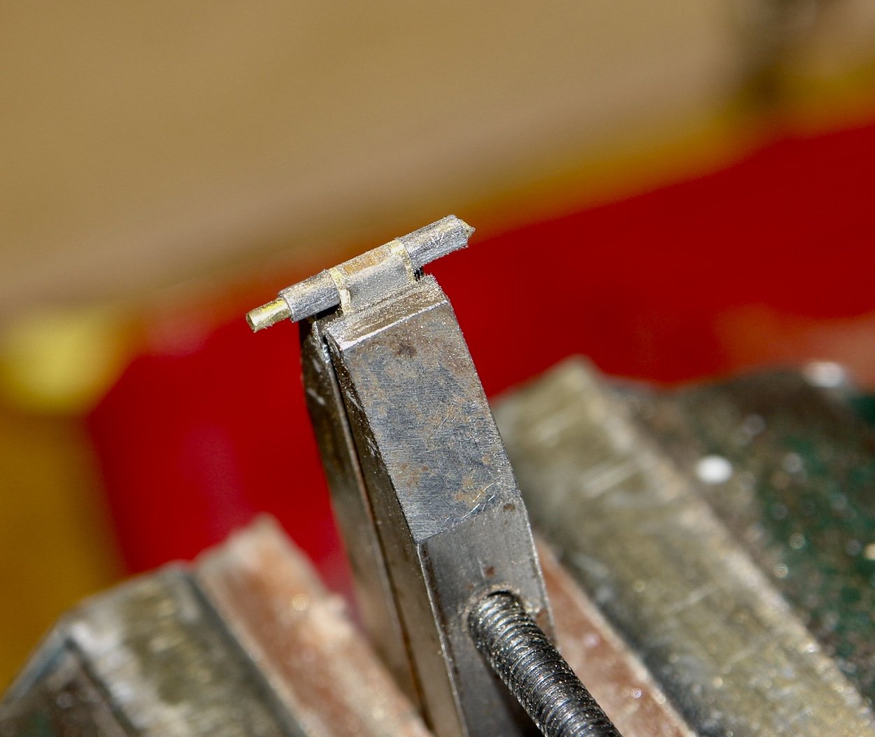
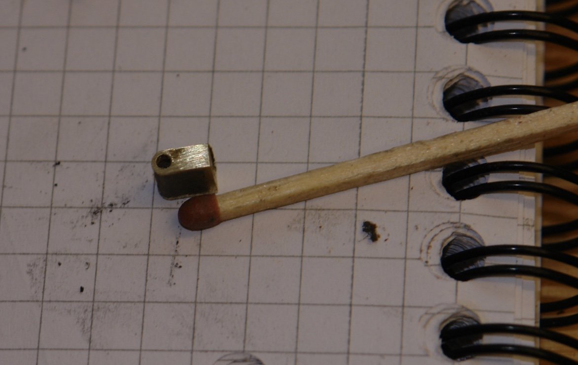
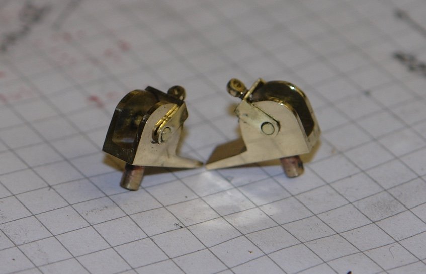
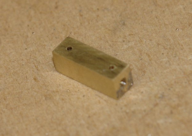
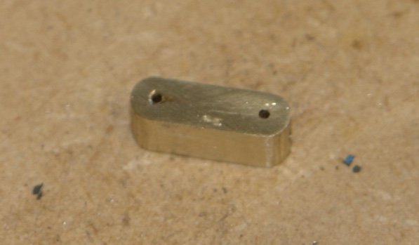
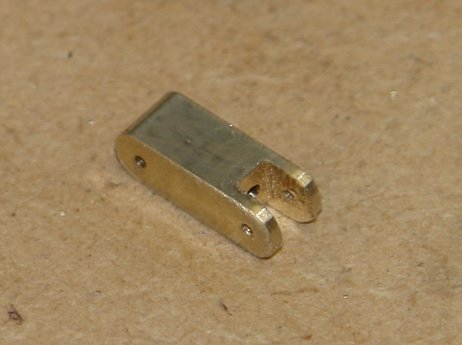
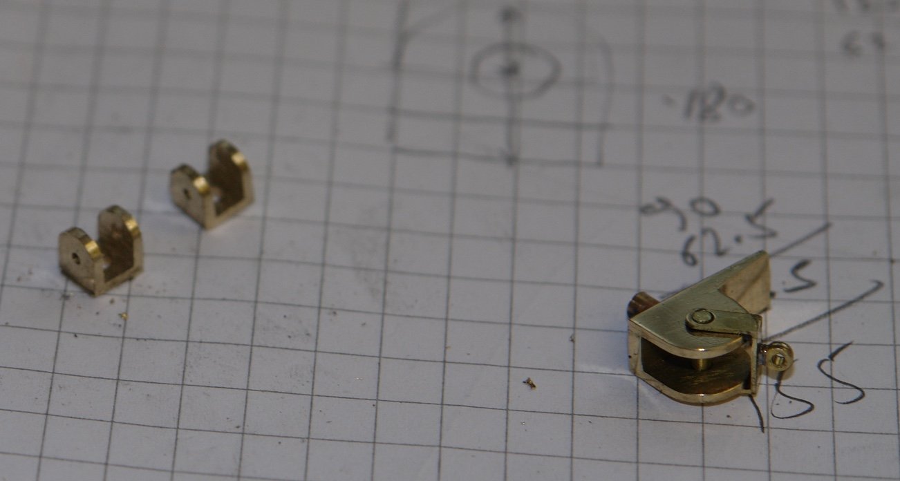
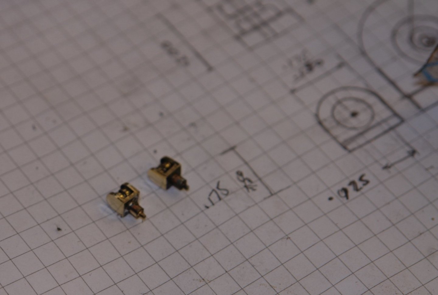
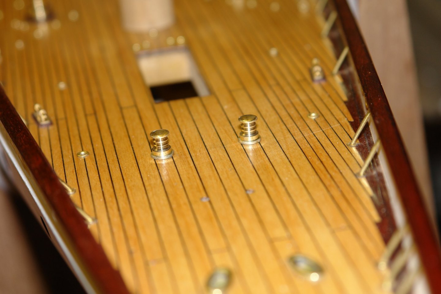
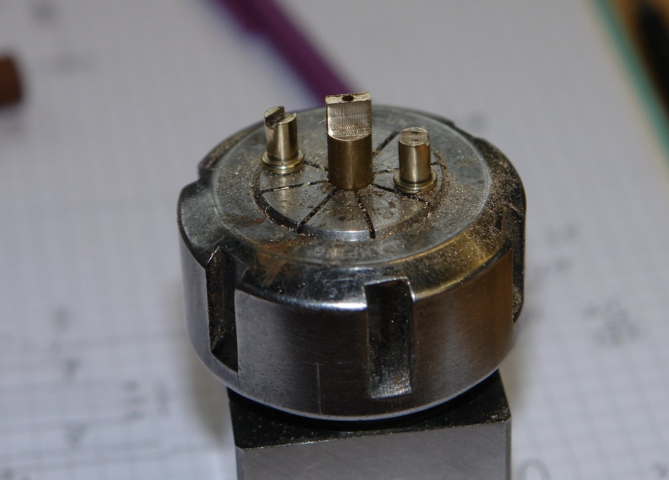
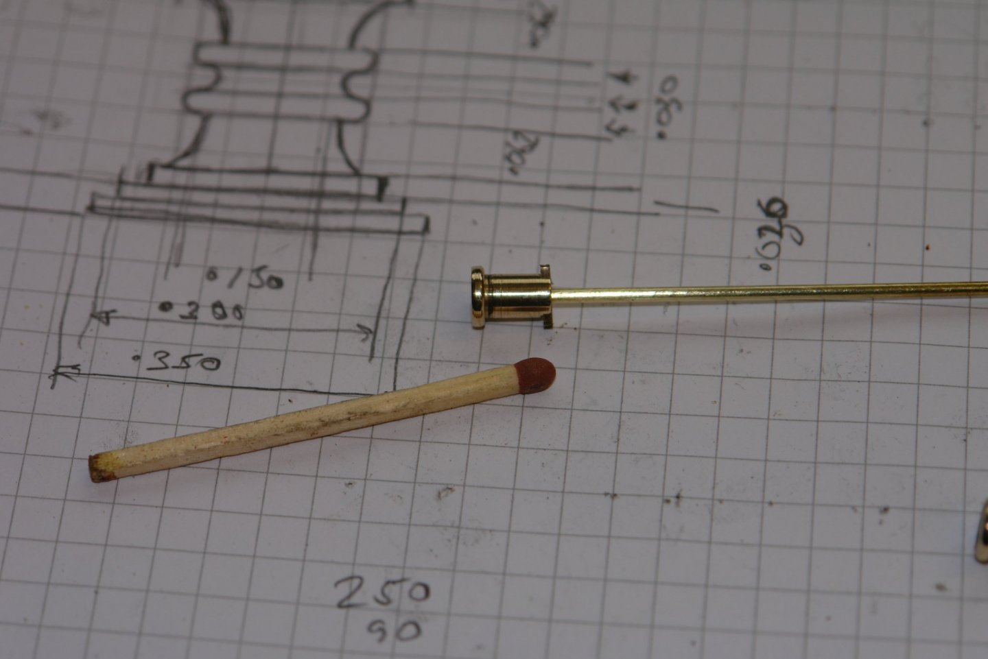
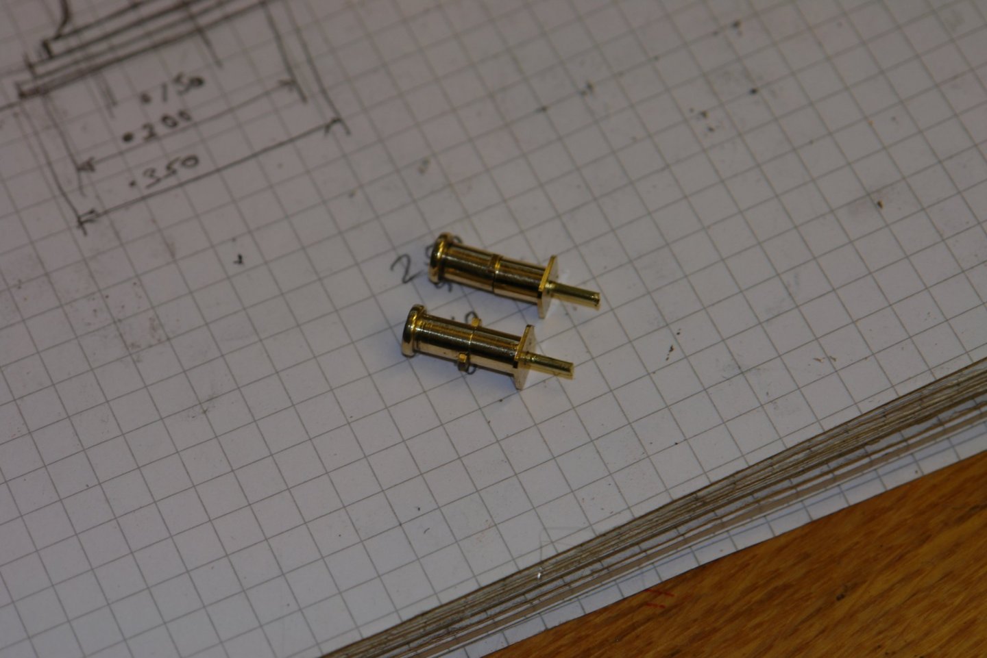
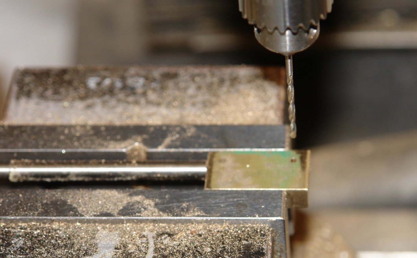
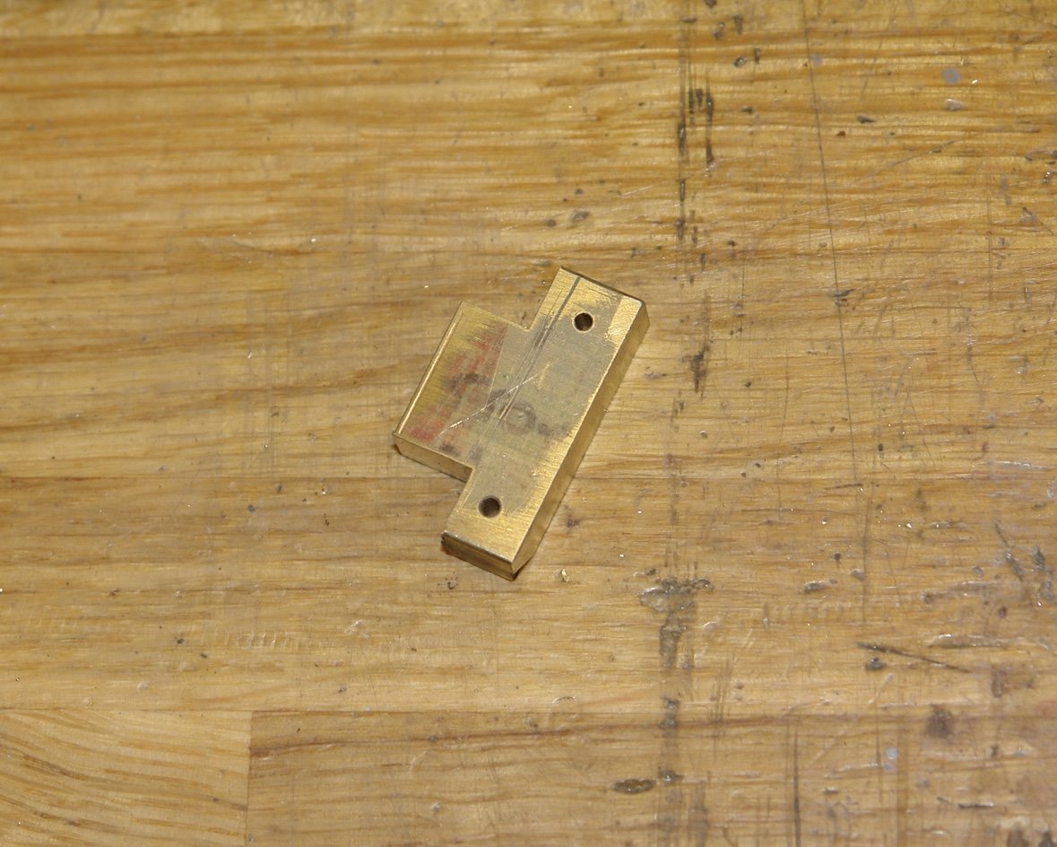
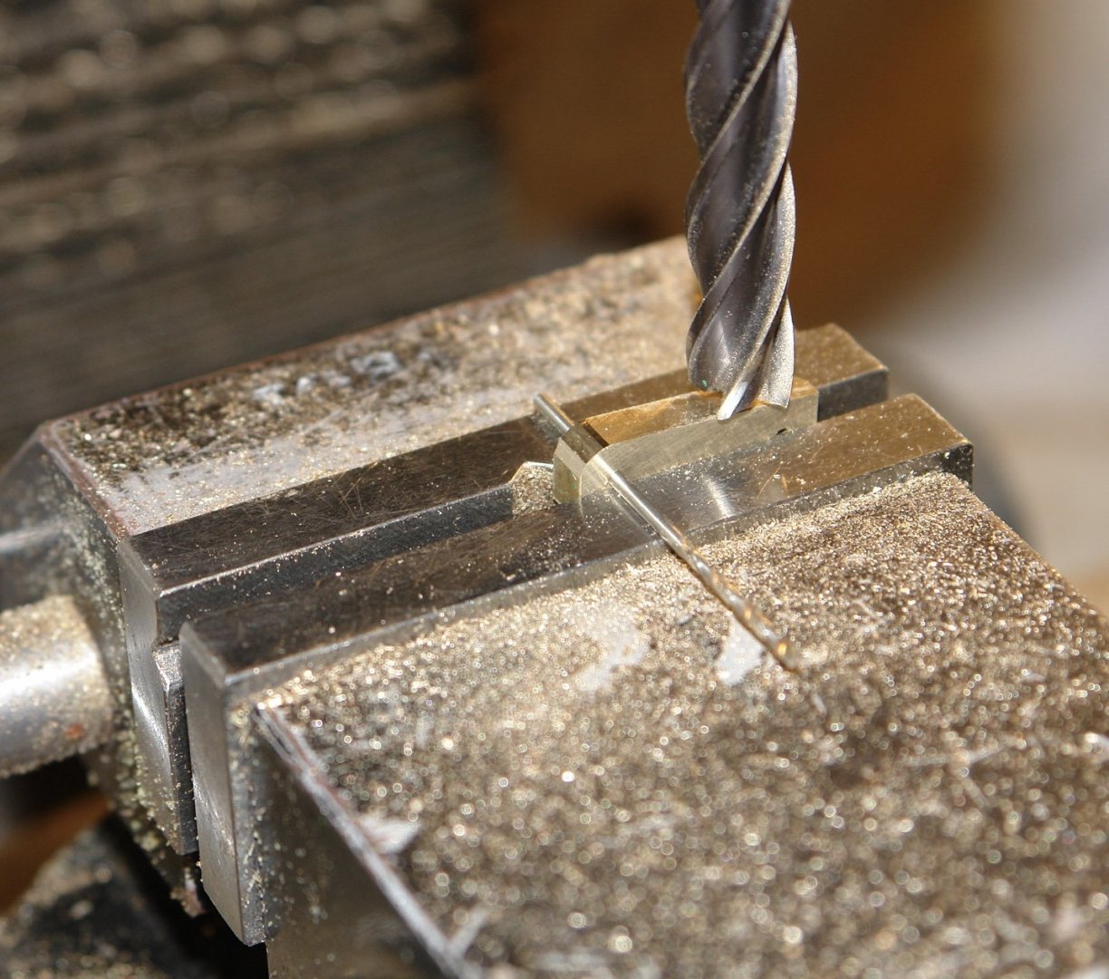
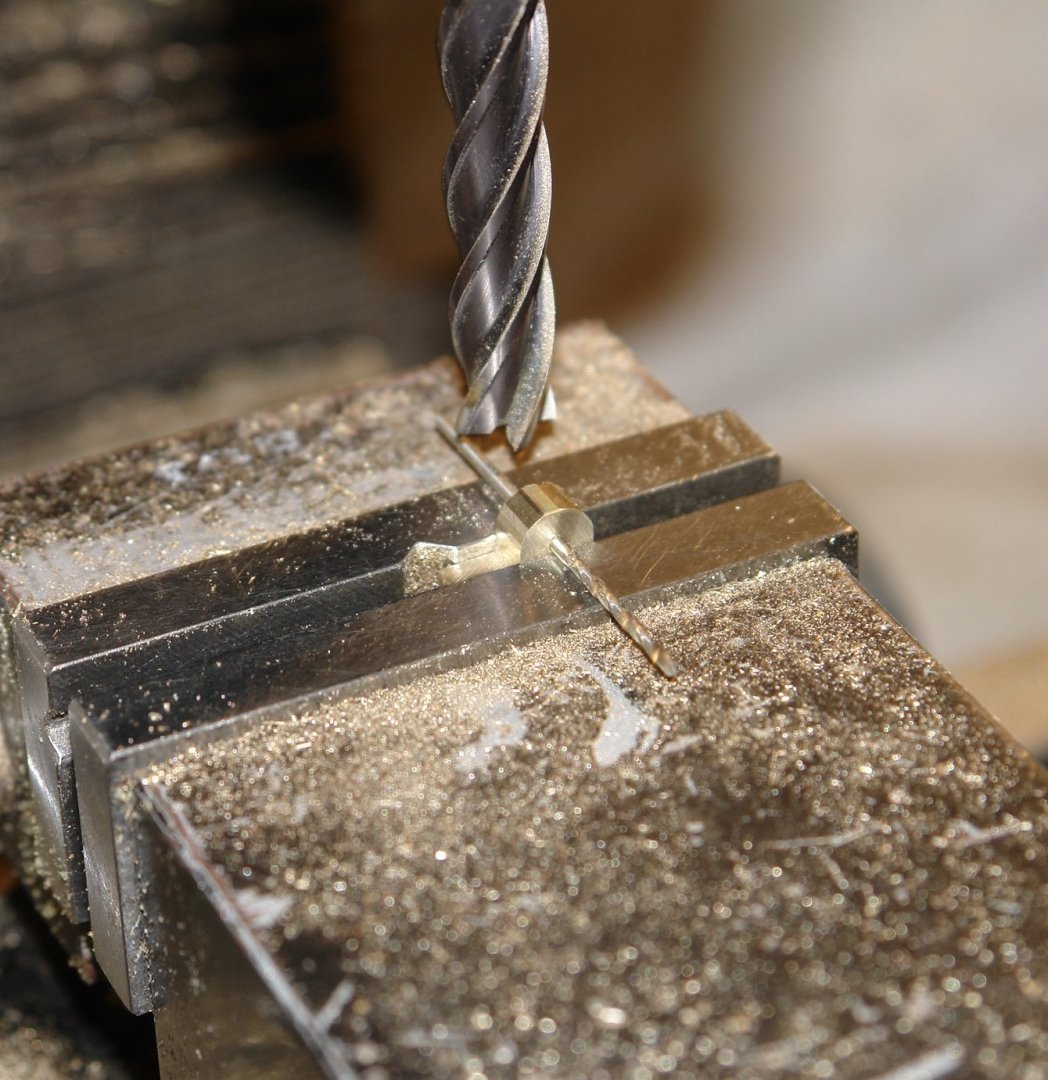
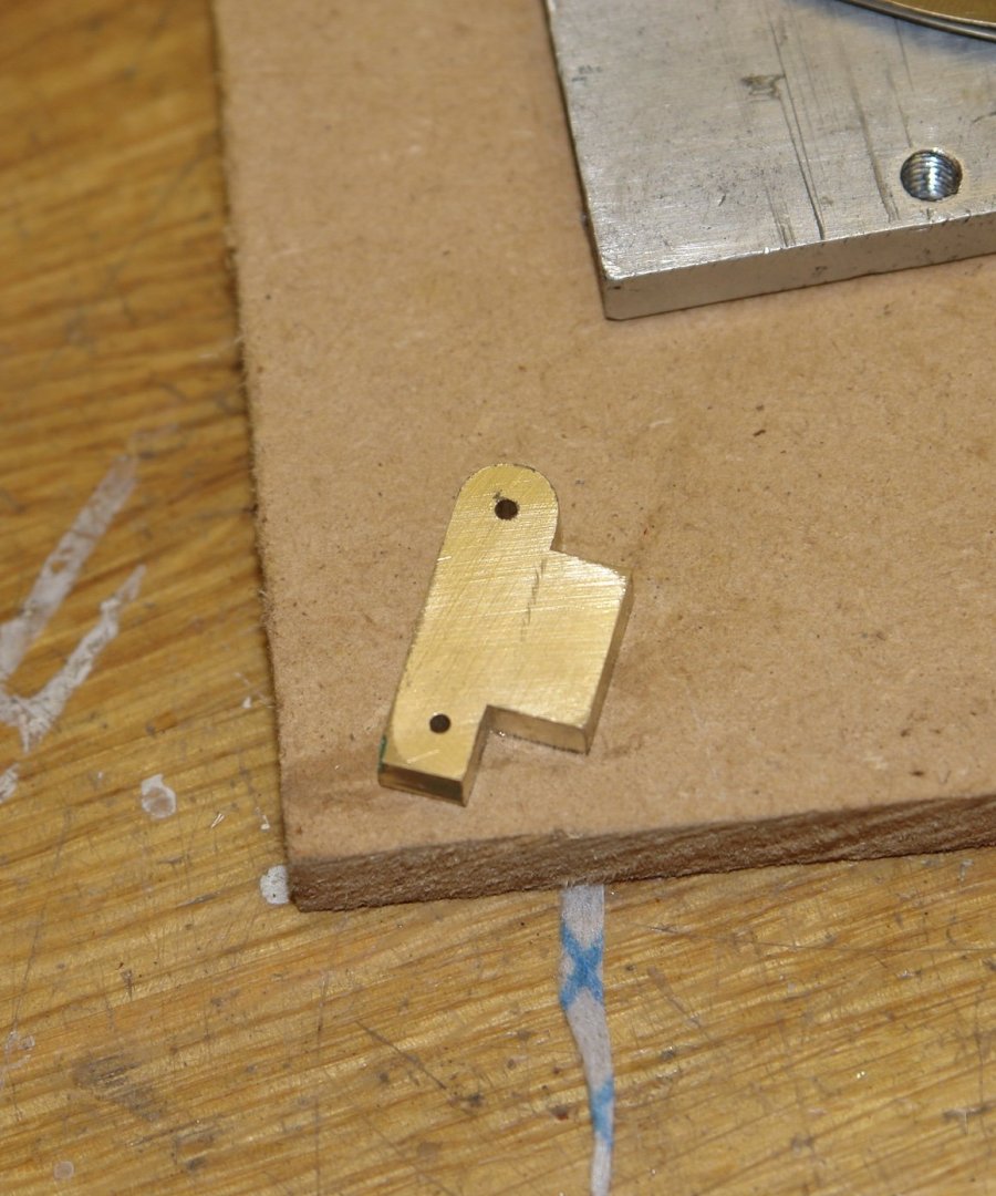
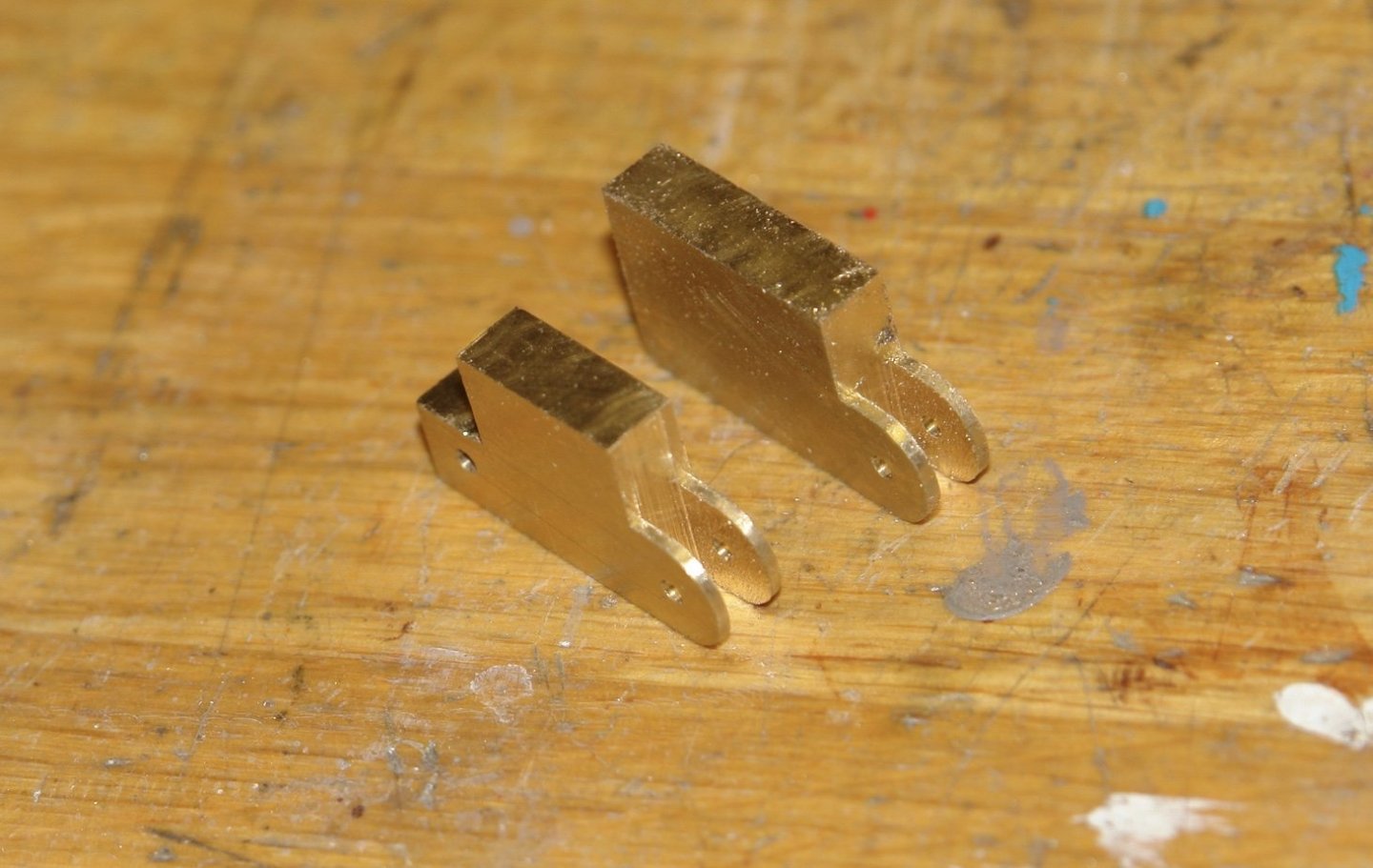
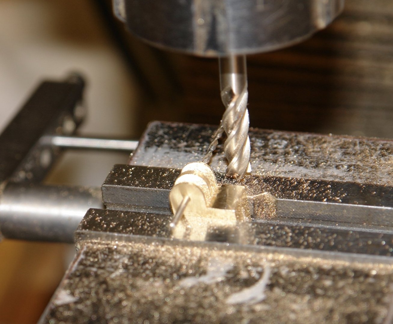
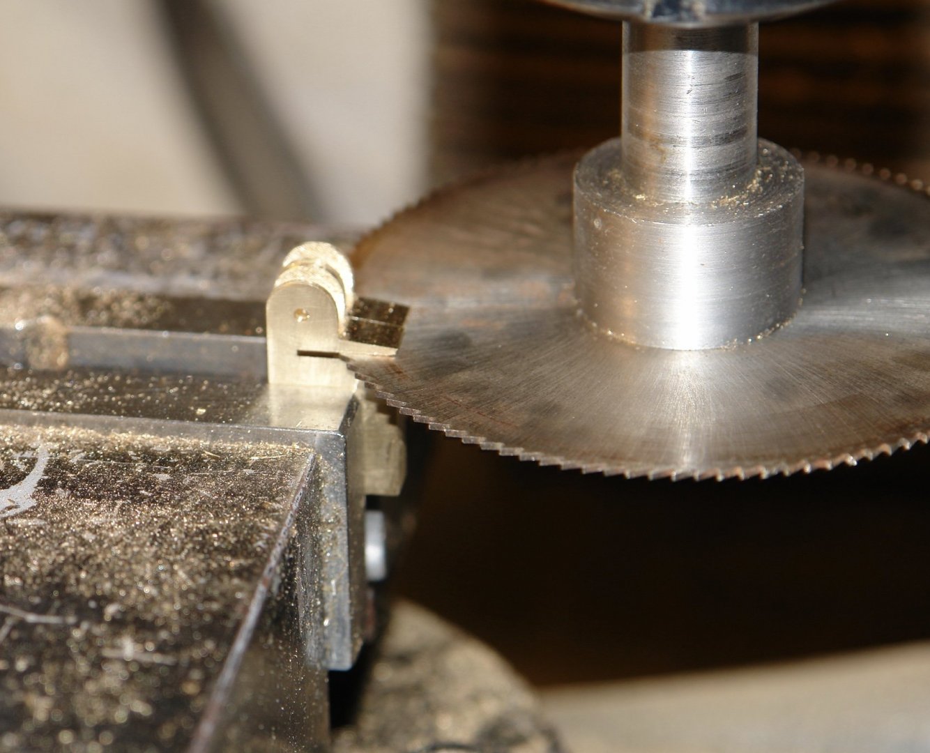
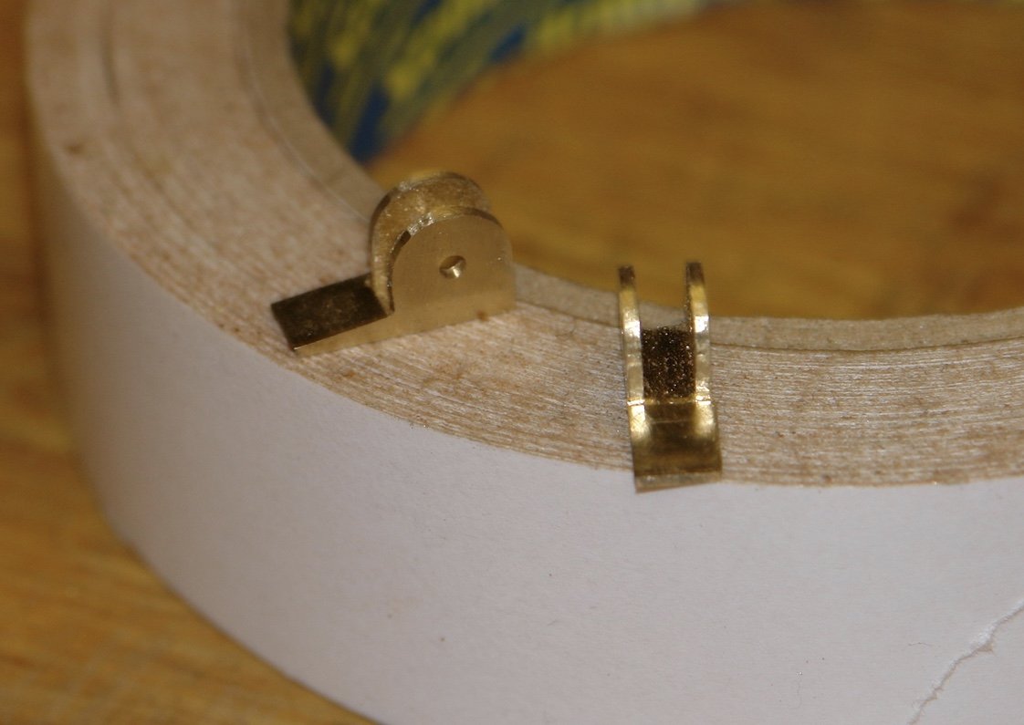
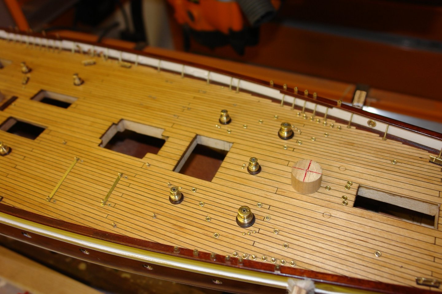
The workshop conditions over the weekend have been tolerable so I have done a bit more brass work. The chain guide bollards were a straightforward turning job. The only complication was I needed rather small turning tools so a bit of grinding was necessary. In the photo they are temporarily placed on the deck minus their circular wooden plinth which will be made later. Having scratched my head for as bit I decided that the lug on the slender bollards would be more easily created if I made the bollards in parts with a split at the lug position. I therefor turned the top portion and then cut a slot to take the lug. The lug itself was milled to shape and then parted off to thickness. A 1/16" central hole was drilled along the axis of all parts for location purposes. The lower section of the bollard was then turned and its square based was milled. All parts were assembled on a central rod and glued with CA glue. I then made a start on the chain lock. I decided that I could make the 2 pawl devices from a piece of brass bar of 1.0"x.55"x.25". I needed a thickness of .2" so I reduced the thickness with a fly cutter. I then drilled the 2 off 1/16"holes for the pivot point of the pawl. I then cut off the waste material.........plus some that wasn't waste material..............the cutter slipped in the collet. So the plan changed to making 1 pawl device from the piece of brass. I milled the circular profile by pivoting the brass in the vice around a central pin (actually a 1/16' drill) - taking a succession of horizontal cuts will the end mill. With a light filing I had the desired circular form. I then slotted out the centre using a slitting saw. I repeated the process to create a second pawl body. The two parts were then aligned through the pivot hole and stuck together using double sided tape. It was then back to the mill to cut the ramp angle on the in-feed side. With the ramp cut the two parts were cut off to height with a slitting saw. I hope to finish tomorrow.


-
Michael - the computer keyboard reminds me how big your model is. I do like the opportunity for detail that it presents. I must consider building smaller ships at larger scale in future.
-
Doris - I wish my eyesight was better to be able to marvel at the detail you create.
- 1,035 replies
-
- 4
-

-
- royal katherine
- ship of the line
- (and 1 more)
-
Michael - screw slots look a little wide and deep .............................. only joking - well done.
-
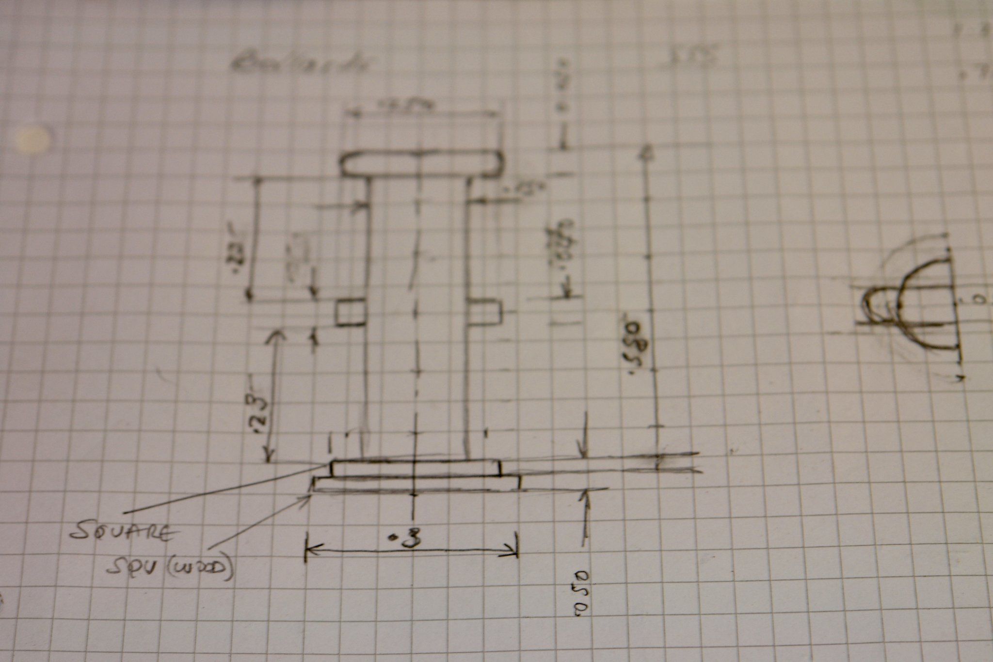
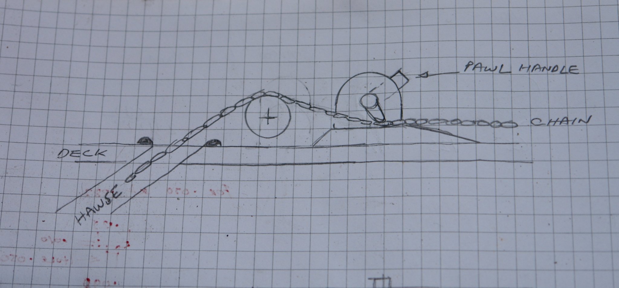
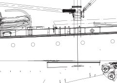
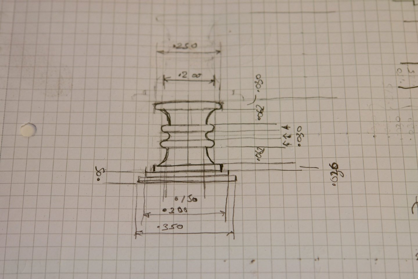
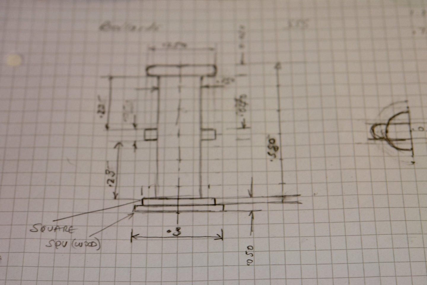
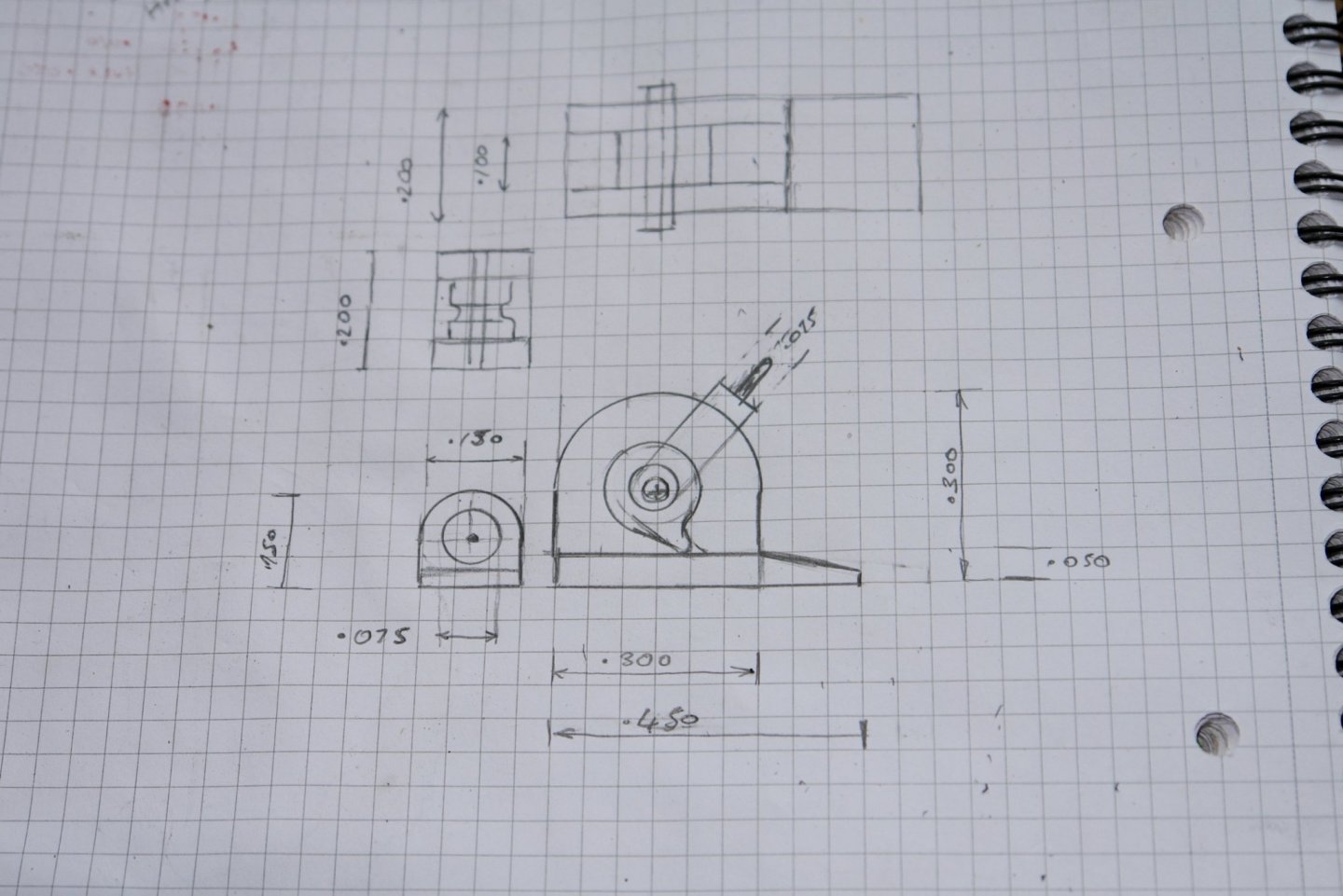
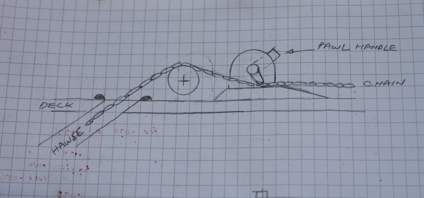
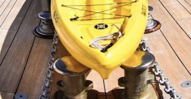
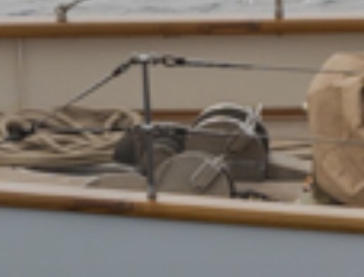
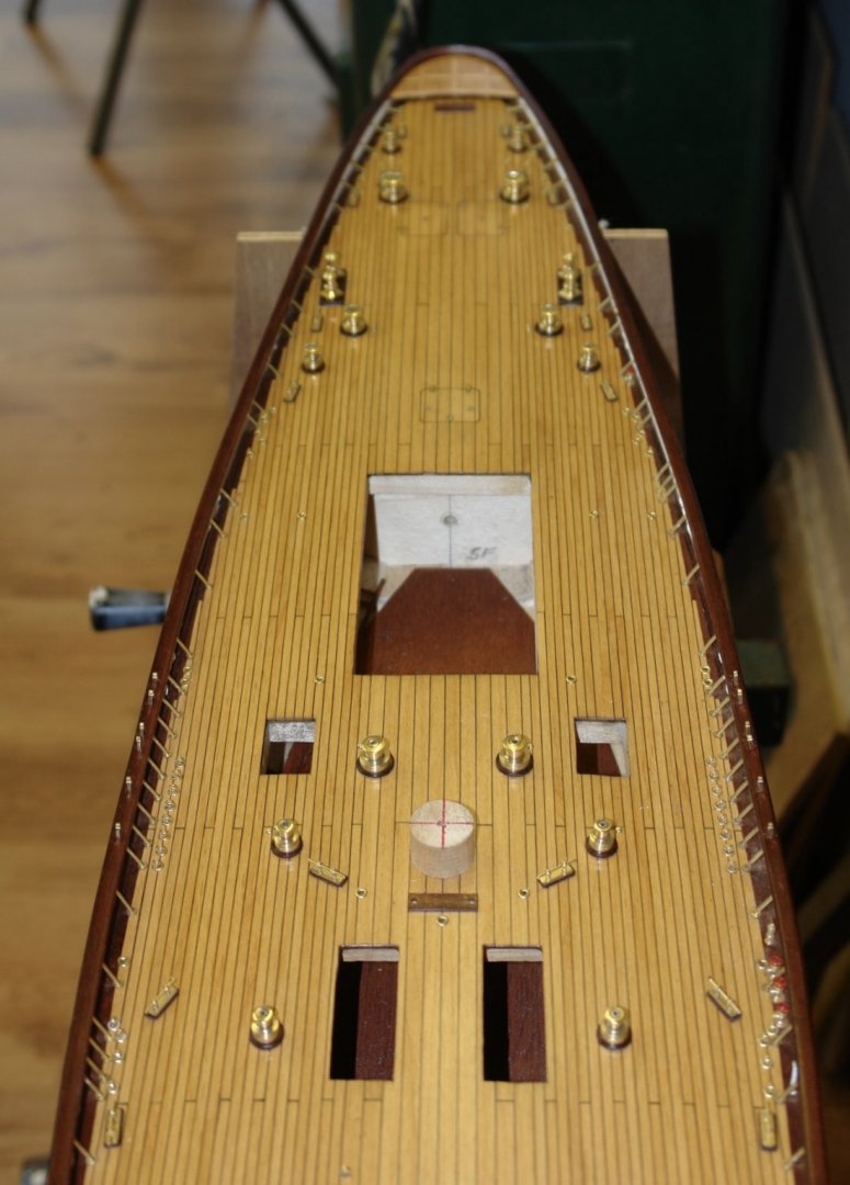
The weather has been somewhat on the cool side and as a result the workshop has been declared out of bounds. I have consoled myself by sitting in my arm chair planning the next steps and making manufacturing sketches from my stock of photographs. I have been focusing on the foredeck and in particular the various features around the anchor chain. In the next photograph you can see a pair of bollards and a couple of chain guides hiding under a plastic canoe. Here are the same features with their location better defined albeit with a loss of detail. The rear most pair appear to be fixed guides and scaling of the photographs enabled me to produce the following sketch. The front pair are quite tall and slender. The lugs will make manufacture of these somewhat more than a simple turning job. Finally I returned to the "chain locking device" that was the subject of a previous discussion. I took the advice that this was some sort of pawl lock and I imagine that it operates something like the depiction in the following sketch. Scaling from photographs produced the following sketch. The weather is forecast to become more stormy and a little warmer so I hope to manufacture these items over the weekend.

-
Thank you Juan. I am hoping that my current build "Germania" turns out as well.
-
Vaddoc - I have a Byrnes saw. I can rip down wood of up to 3/4" thick using the carbide blade this has a .055" kerf. I limit my slitting saw blades to wood less than .250" thick. I typically use a .0315" blade. I usually get planks to within +/- .002" of the desired thickness.
-
She is a pretty little vessel Javier. The sails are nicely shaped - what are they made from?
-
accurate-armour micro saw
KeithAug replied to michael101's topic in Modeling tools and Workshop Equipment
Michael - you are correct - the tooth pitch is circa 1mm and therefore it does not work well on anything of 1mm thickness or less. -
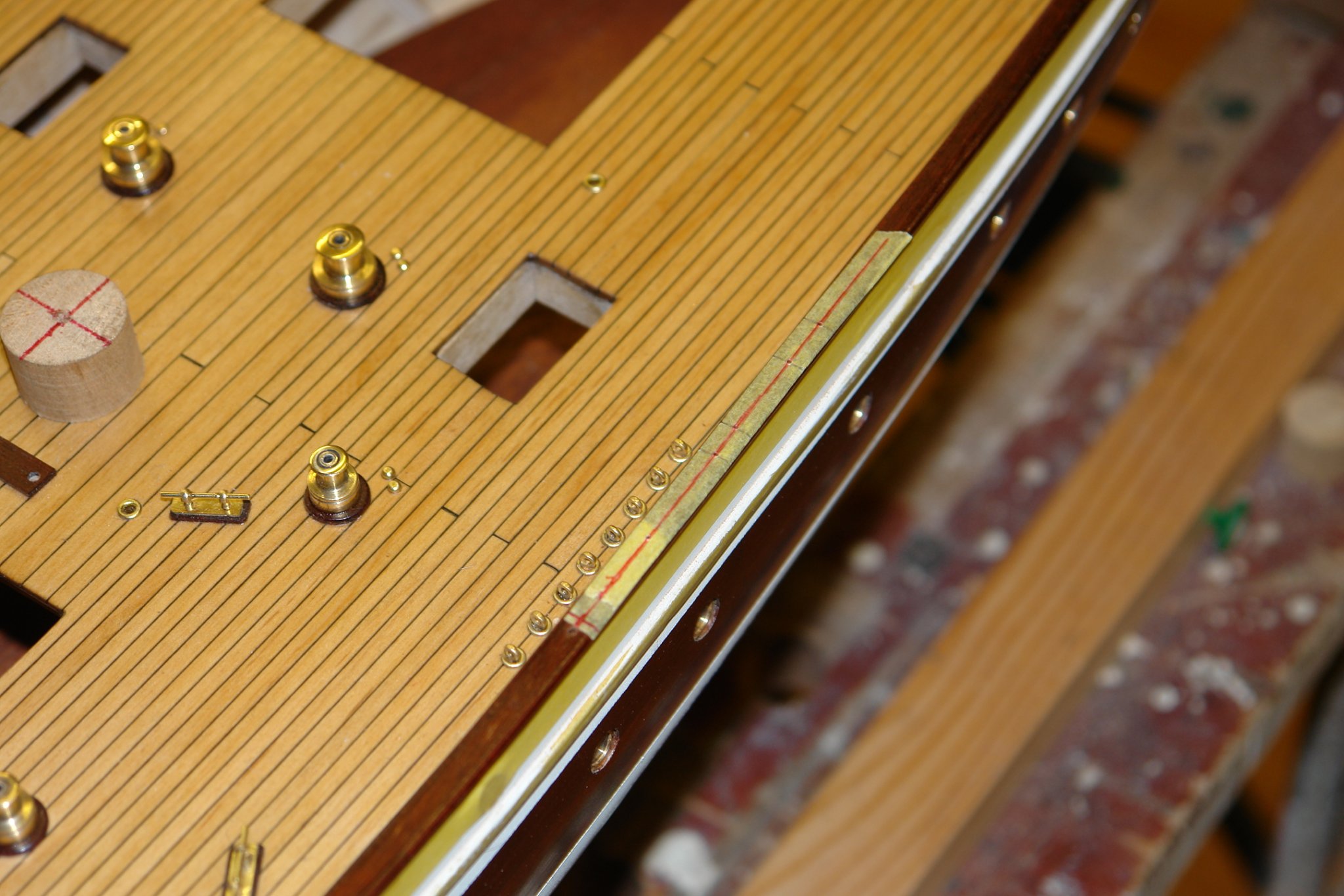
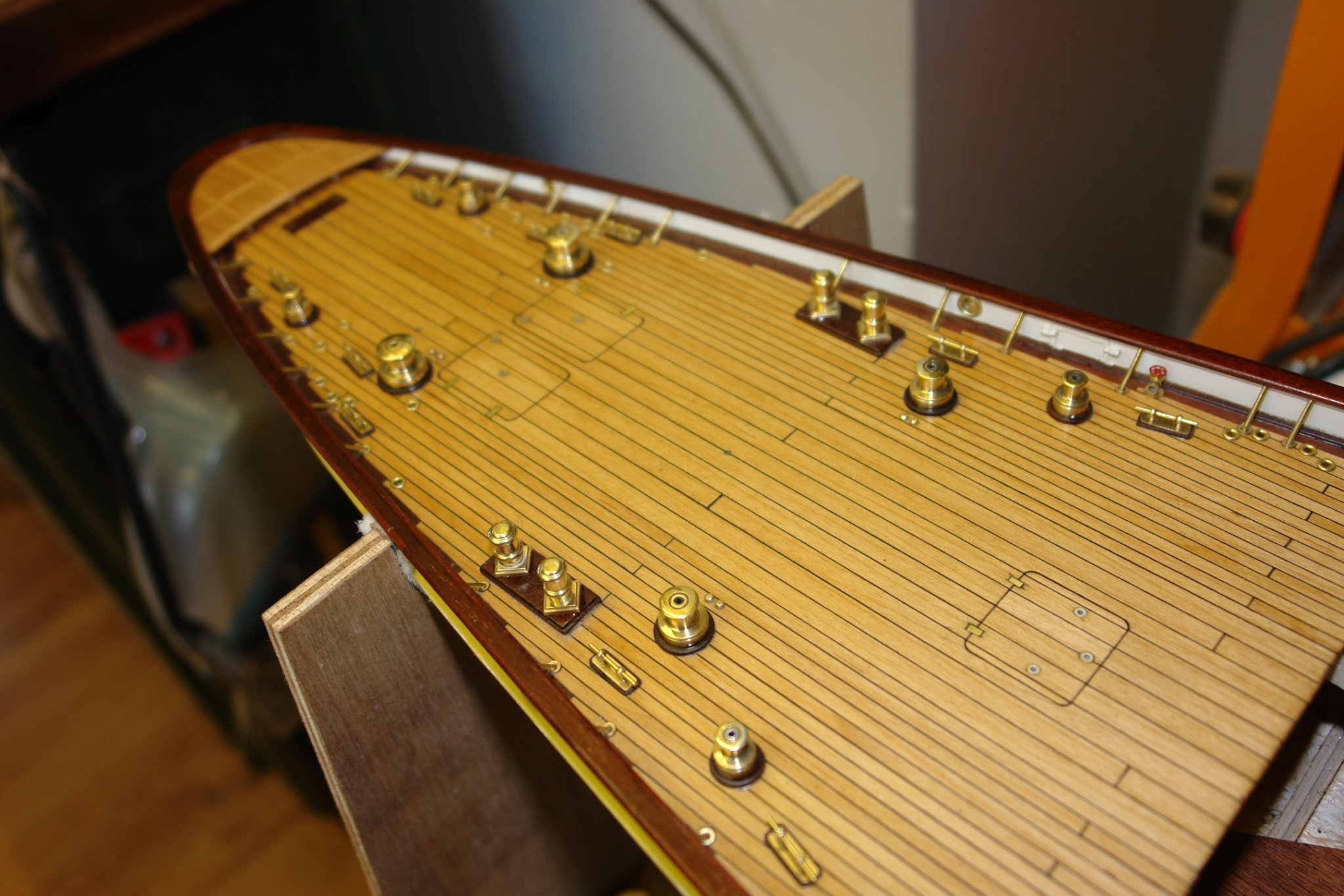
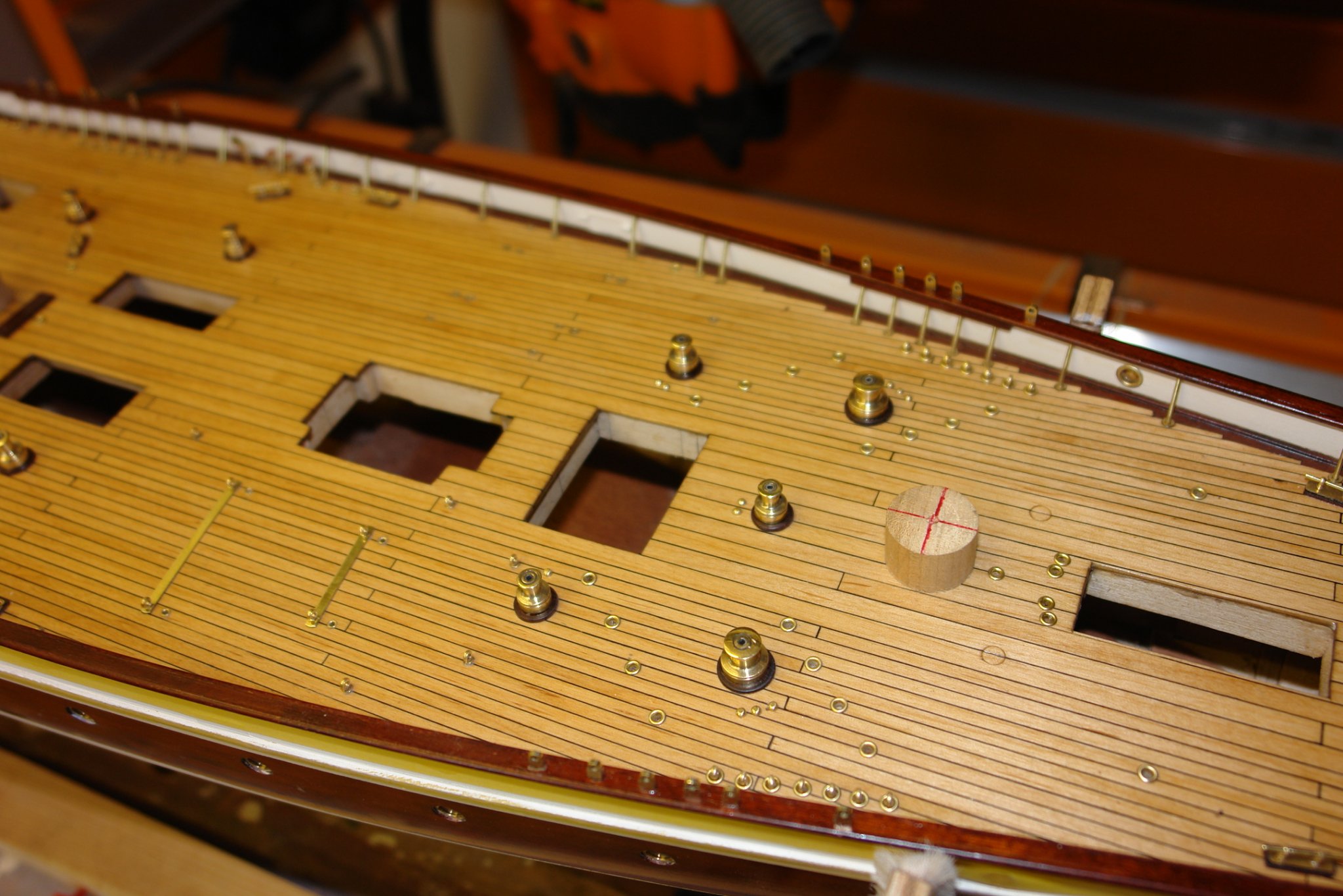
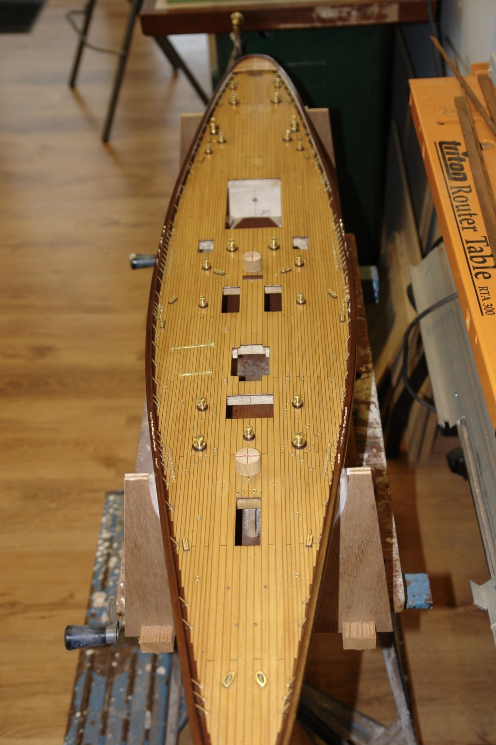
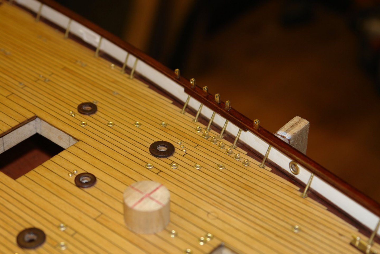
Thank you Gary. Progress seems to be slow at the moment, made more so by the sudden cold spell. Not much fun in the workshop over the last few days and hence limited time. I applied tape to the rails in the areas of the shroud brackets and marked the centre line. While I was at it I started to glue in the winches. I cross checked photos of the bracket positions against the plans and found them to be accurate. I marked off the positions for the brackets and drilled the rails to take the bracket spigots. The brackets were then glued in using CA glue. And a few more shots of the installed winces:-


-
Michael - yes beyond my budget as well. I buy a lot of my tooling from a British based supplier (Chronos) - but as ever these days much of the stuff originates from the far east. That said I find their HSS slitting saw blades to be of good quality. I think they ship worldwide. https://www.chronos.ltd.uk/product-category/gear-cutters-slitting-slotting-saws/metric-hss-slitting-saws/ https://www.chronos.ltd.uk/product-category/gear-cutters-slitting-slotting-saws/imperial-hss-slitting-saws/ Of the far eastern manufacturers I find Soba (Indian) equipment to be well engineered and they do make slitting saw blades.
-
At least you didn't burn it in disgust. It is always better to step away, I wish I could be as disciplined. Great recovery.
- 599 replies
-
- 4
-
-
- sidewheeler
- arabia
- (and 4 more)
-
I have to agree Eberhard. I went a year ago and was pretty unimpressed. I think the decline mirrors the nations move from engineering to a service economy. Michael. I find that I prefer the smaller diameter slitting saws which when combined with a decent thickness seem to run more true and hence are more accurate. Interesting use of Allen key although I think I would prefer to use the slitting saw for this sort of task. I will need hinges at 1/36 scale some time in the future so we will see how the method scales.
-
Thank you Bedford / Mark. Mark. I find CA glue is very strong when gluing closely fitting shafts into bores. I even use it to glue parts on to shafts when I want to turn them and it invariably survives the turning operation. I don't think it is a strong as solder but it can be a bit more convenient and leave less of a clean up operation.
-
accurate-armour micro saw
KeithAug replied to michael101's topic in Modeling tools and Workshop Equipment
I used something similar and didn't find them very good. Have you considered the X-ACTO #15 Keyhole Saw Blade. I use them and find them reasonable. -
Vaddoc - Ah! hadn't understood that. As you say, I also don't know any UK suppliers who supply milled "exotic" timber suitable for scale modelling, pity really but as Michael pointed out we probably don't create the volume of sales to constitute a viable market. If you ever need a bit of wood milling down I would be happy to do it for you