HOLIDAY DONATION DRIVE - SUPPORT MSW - DO YOUR PART TO KEEP THIS GREAT FORUM GOING! (Only 44 donations so far out of 49,000 members - C'mon guys!)
×


KeithAug
-
Posts
3,957 -
Joined
-
Last visited
Content Type
Profiles
Forums
Gallery
Events
Everything posted by KeithAug
-
 Yes Vaddoc - I find myself shying away from remote suppliers because I am never confident about quality.
 -
Really neatly done Gary. I particularly liked your recycling approach to rivets. I must use your method for pillow blocks some time.
-
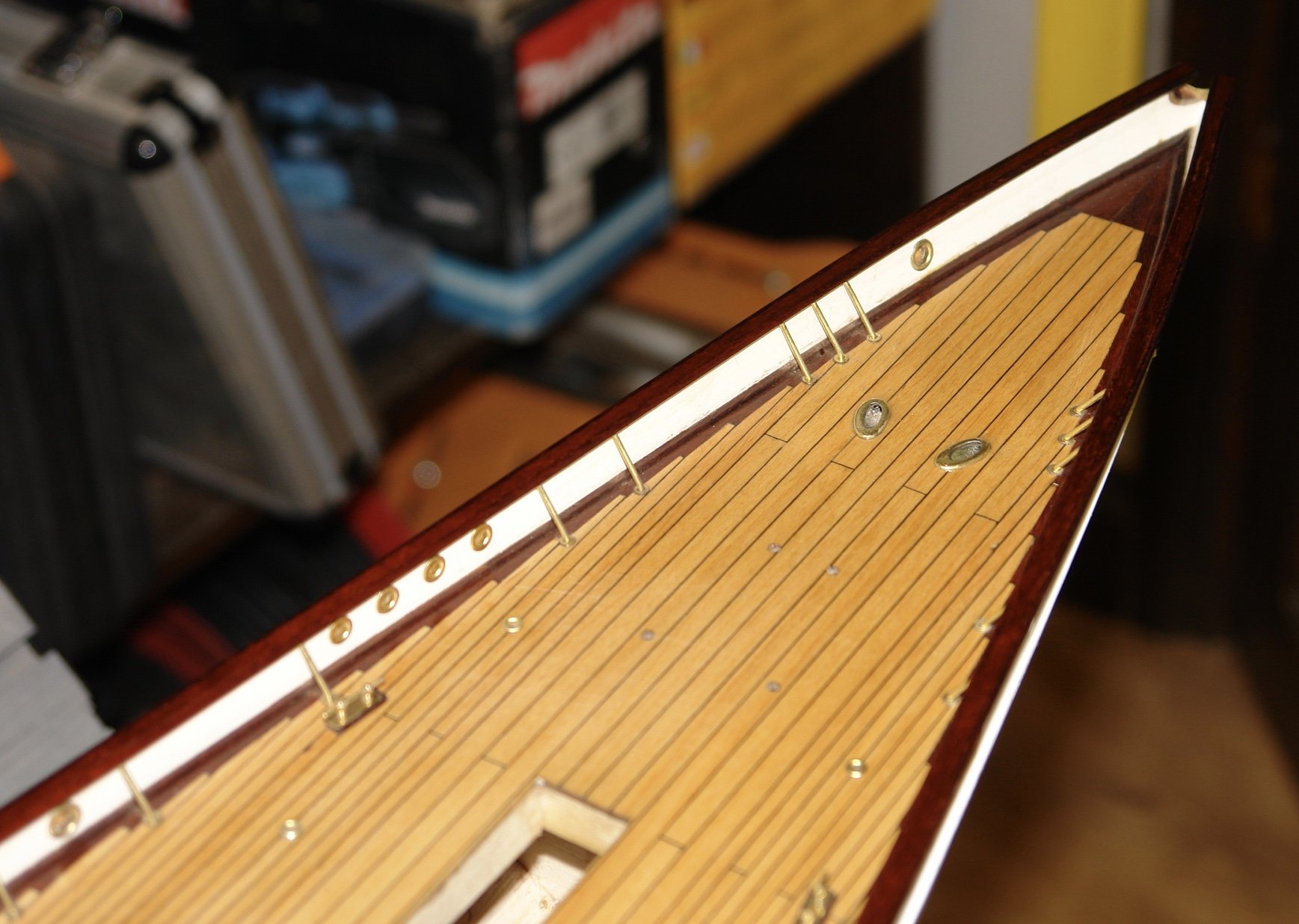
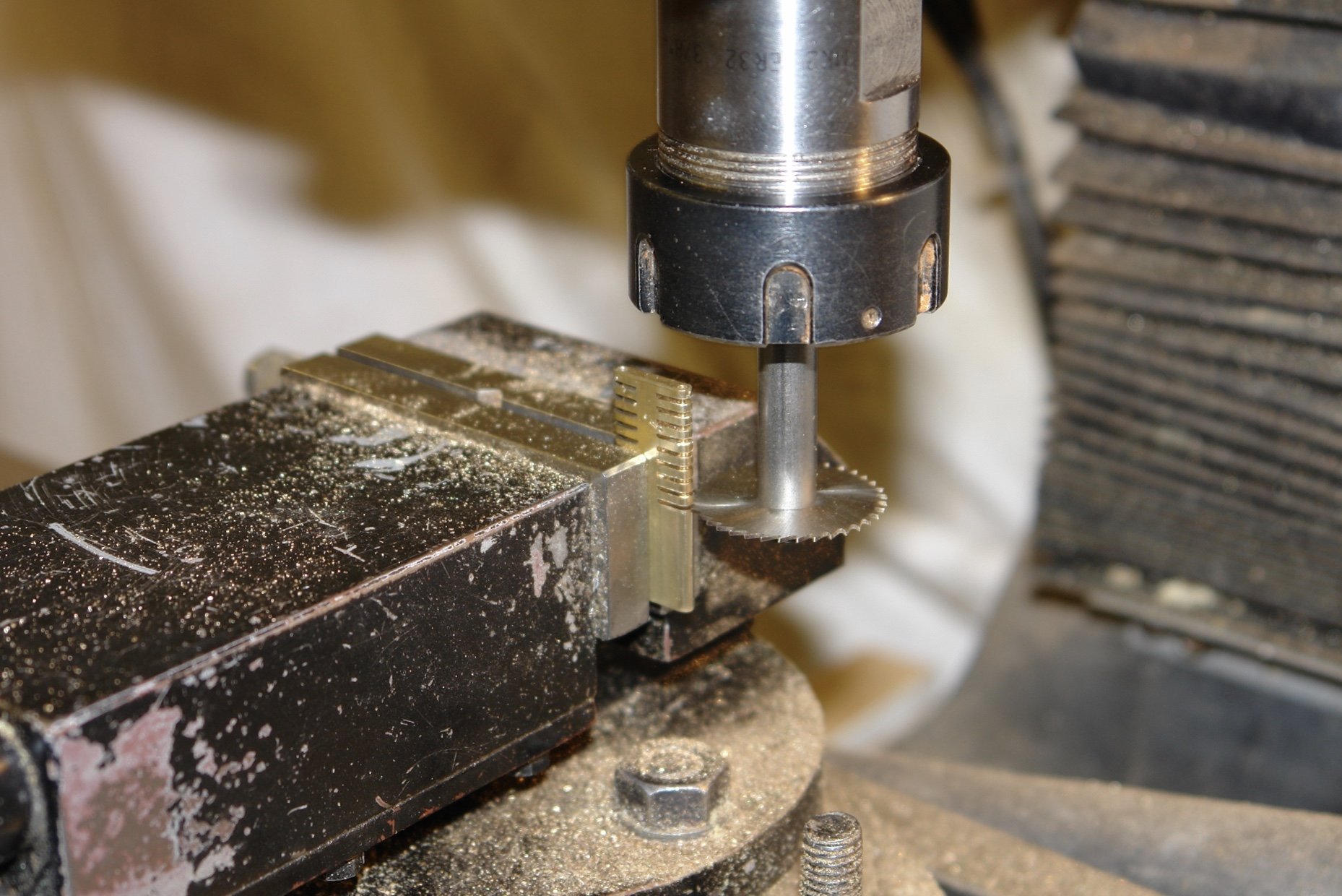
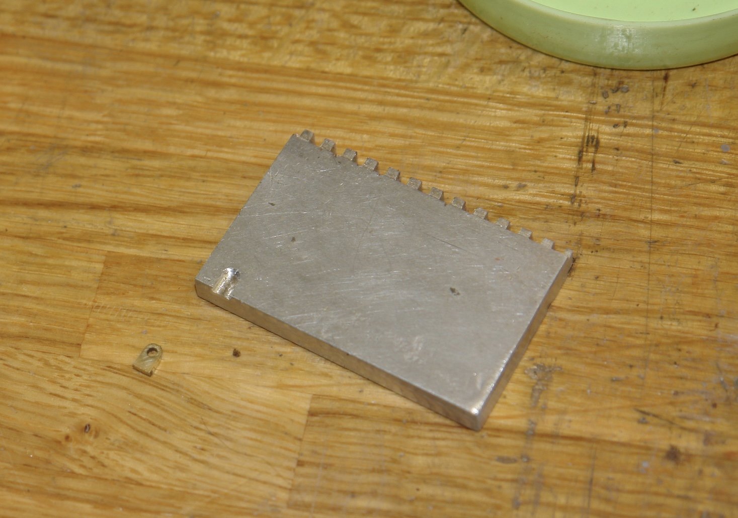
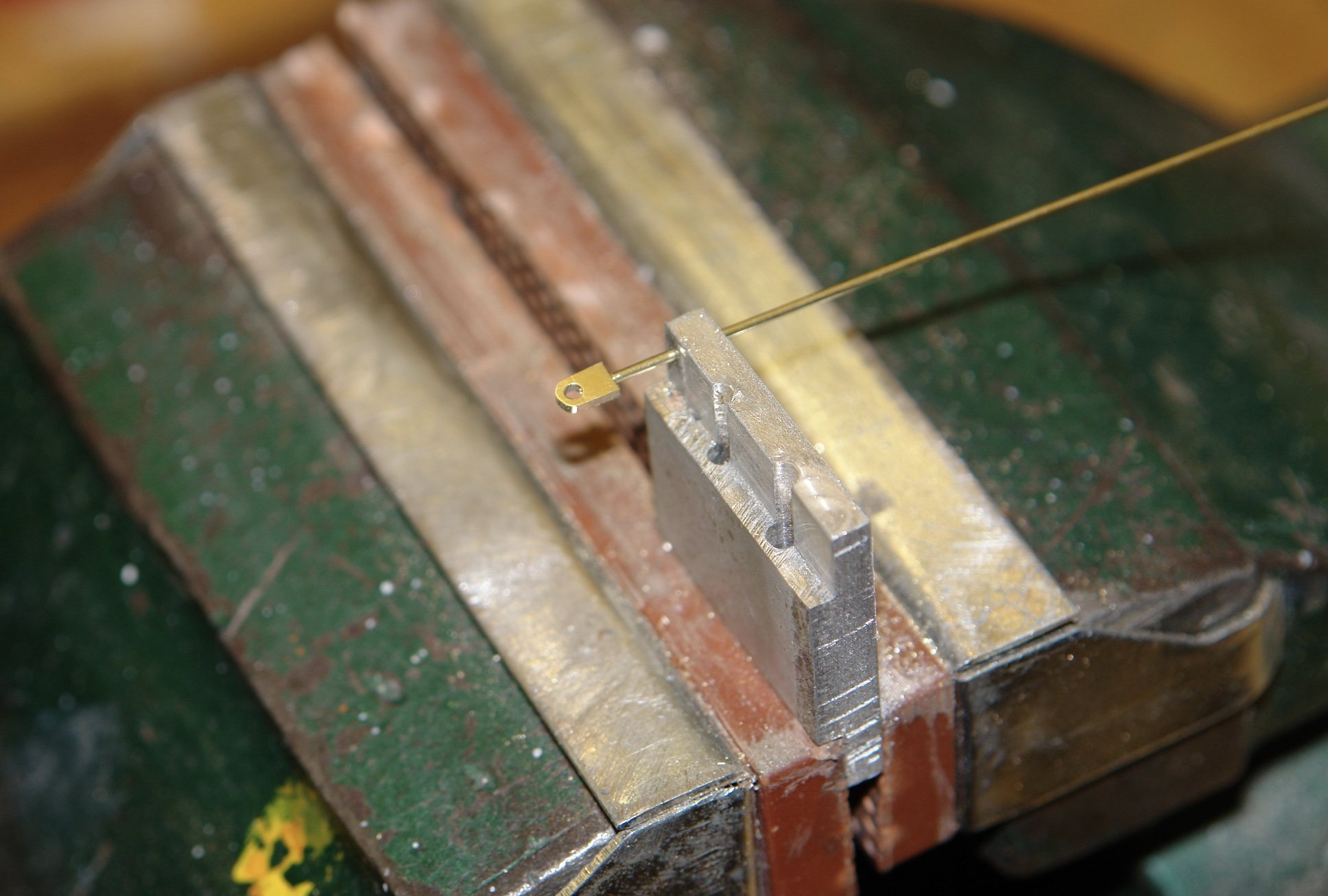
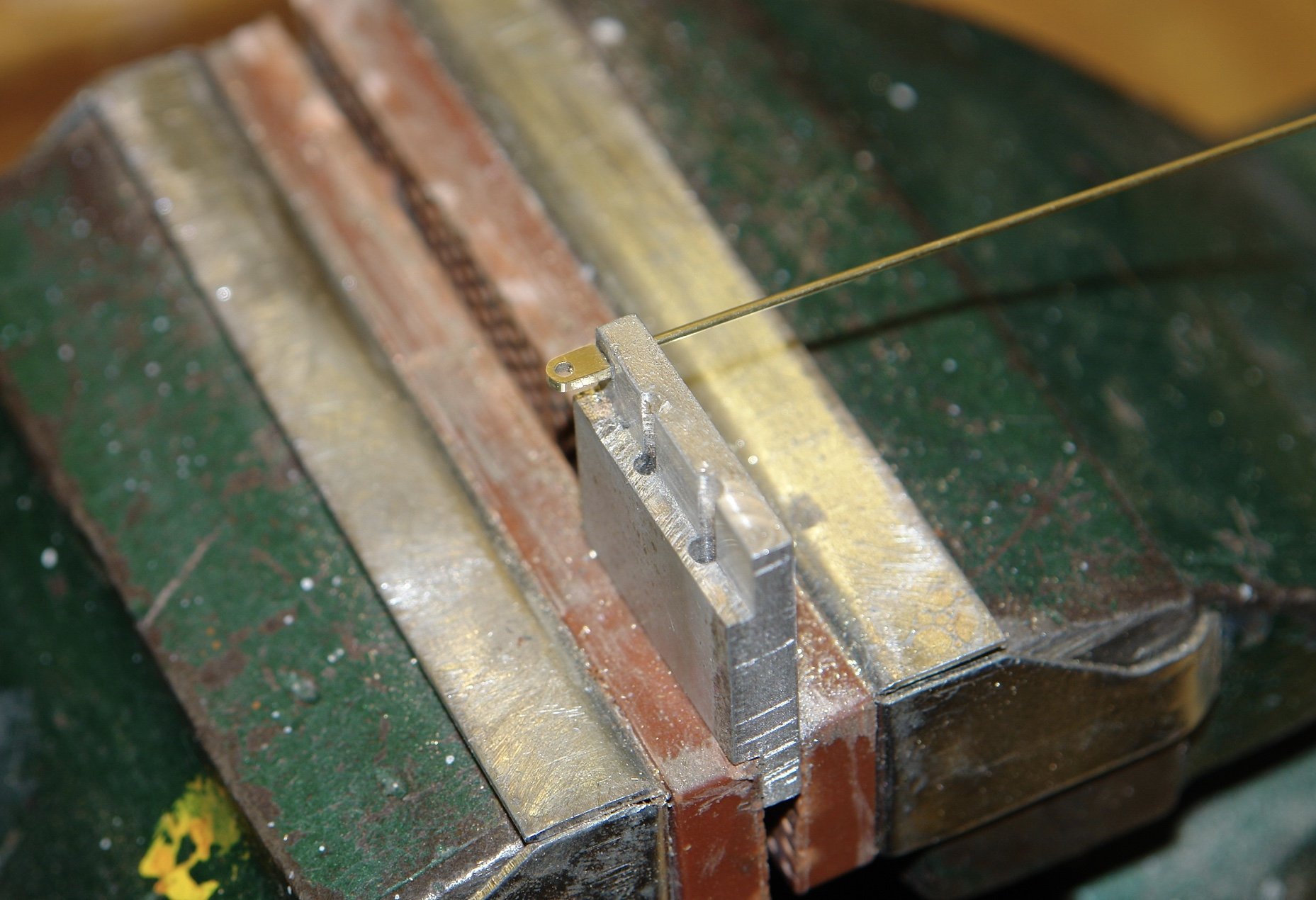
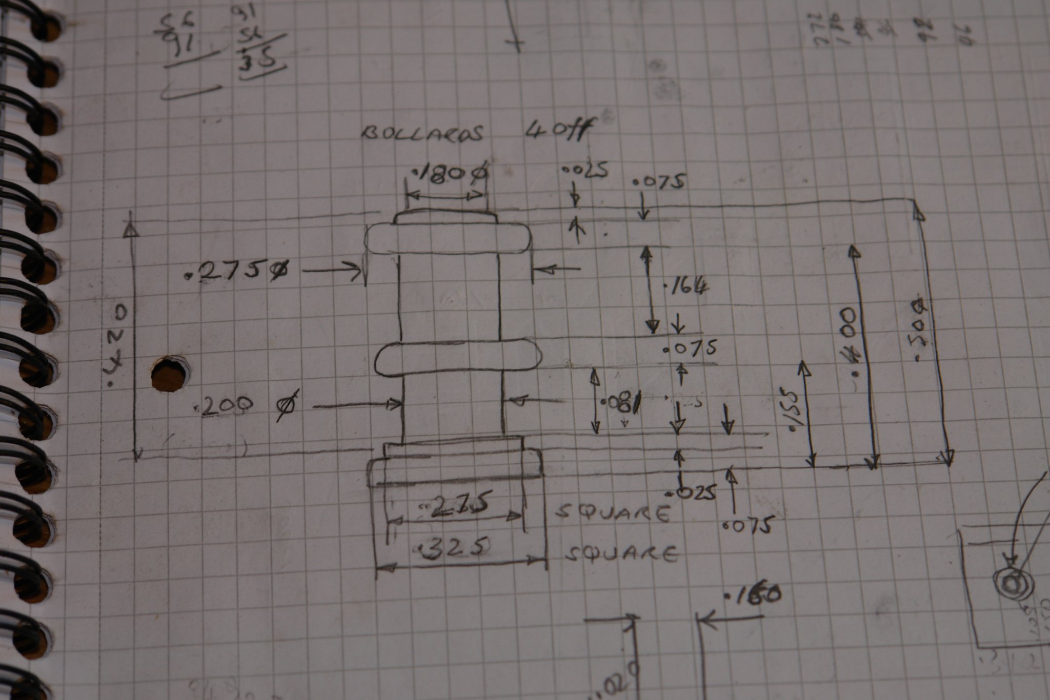
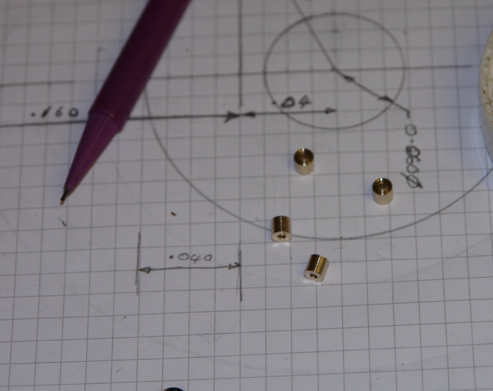
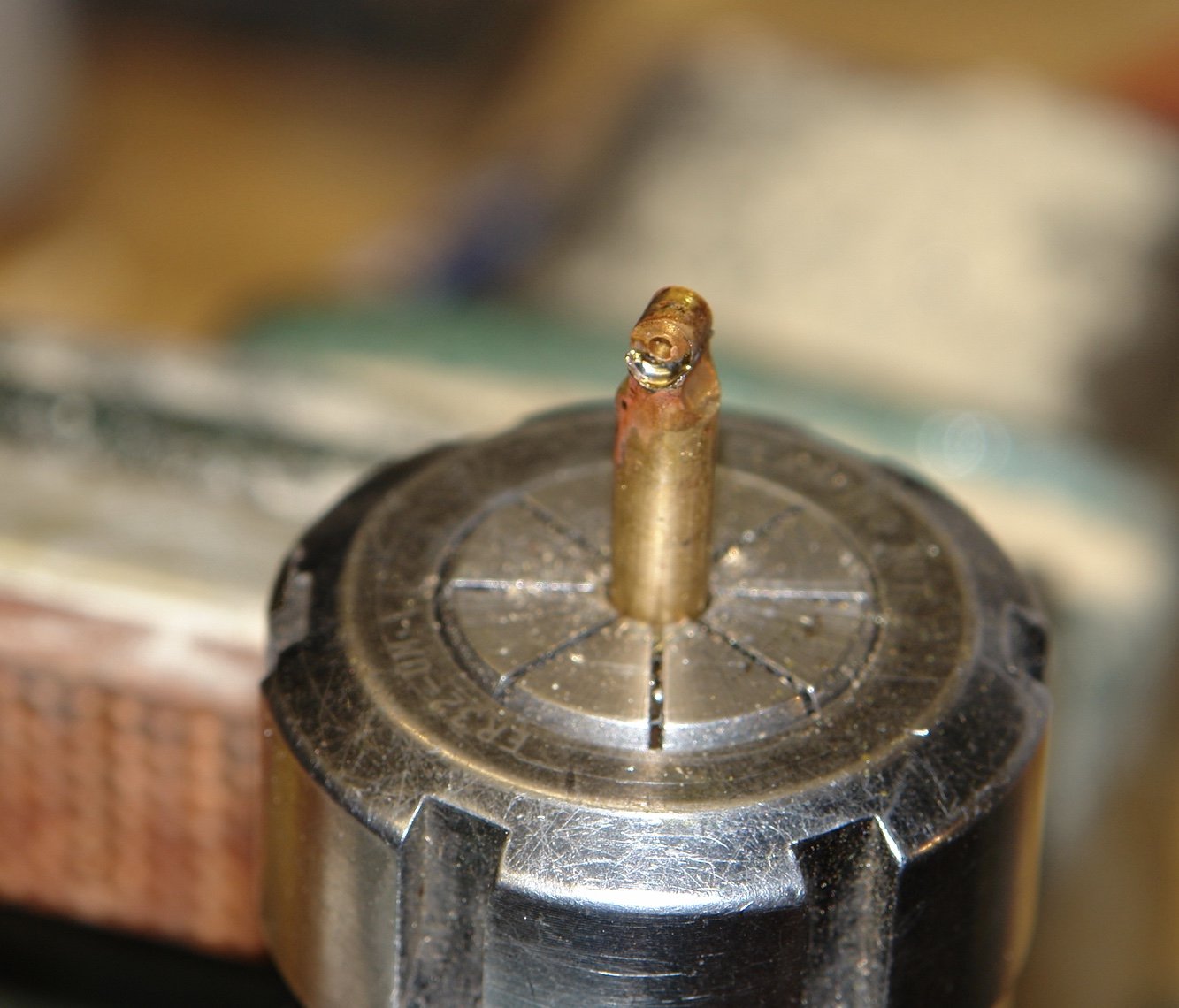
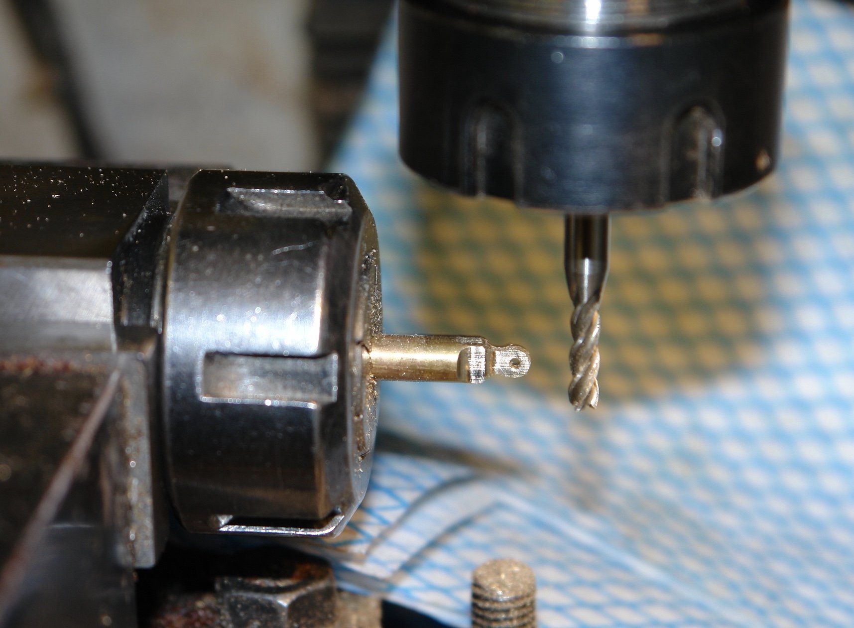
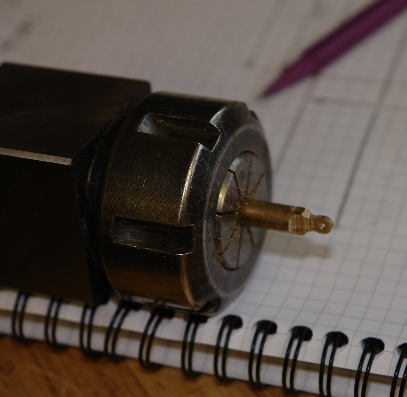
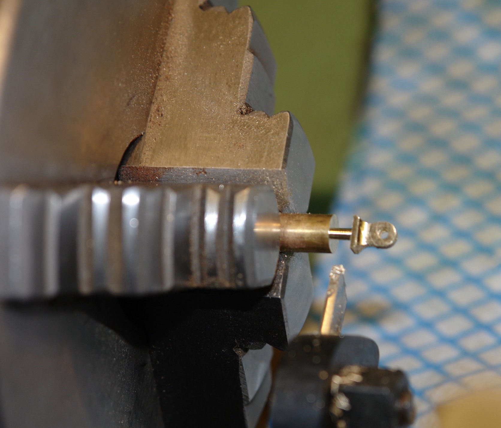
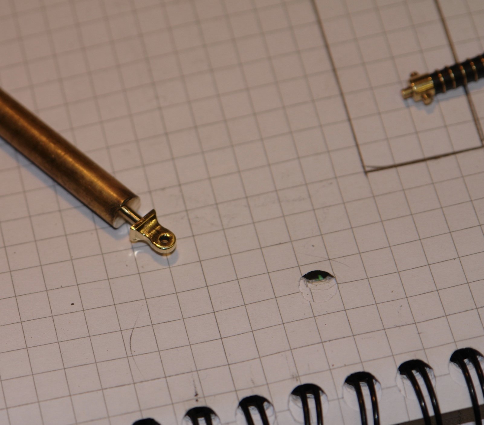
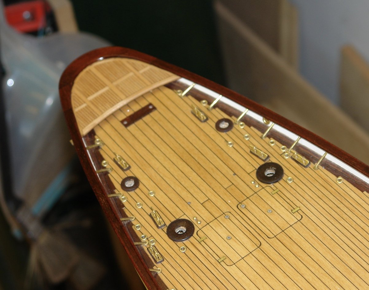
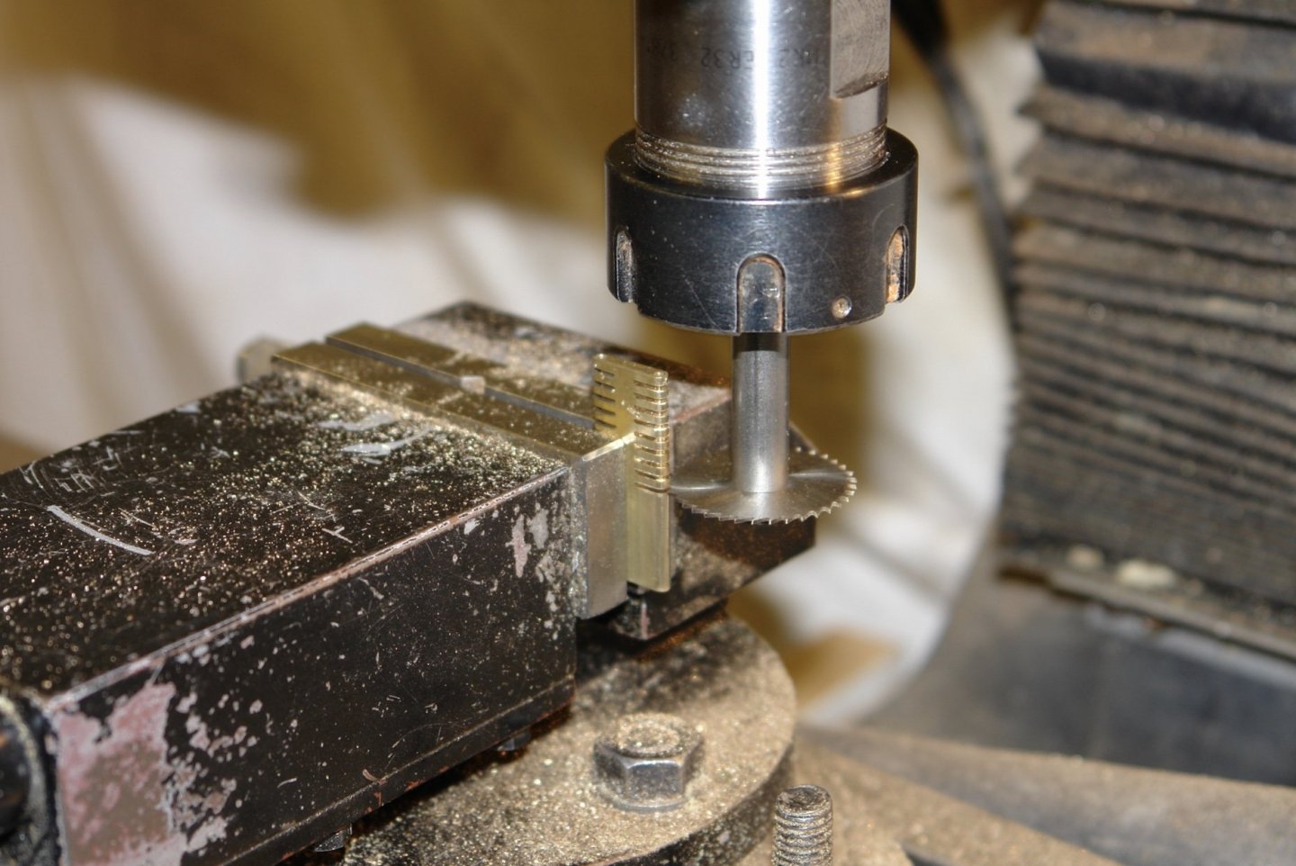
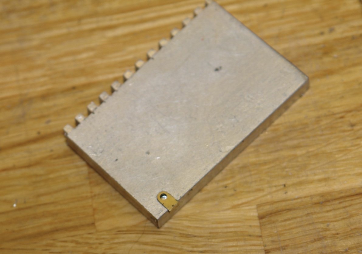
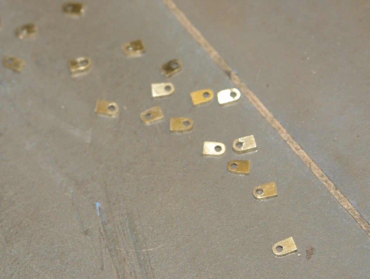
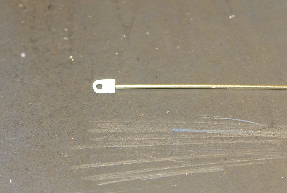
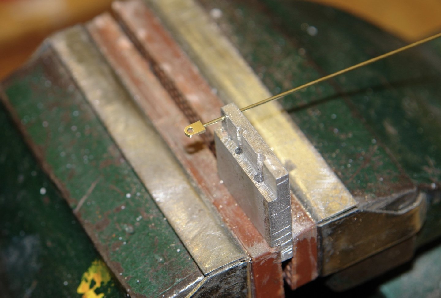
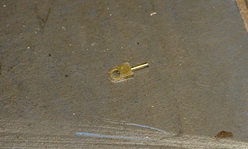
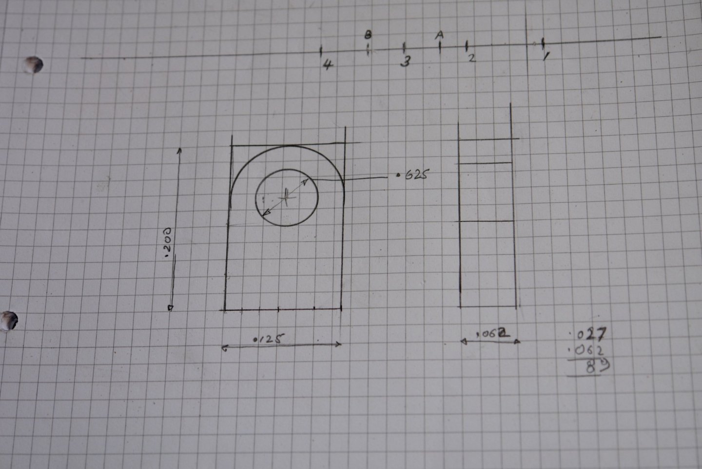
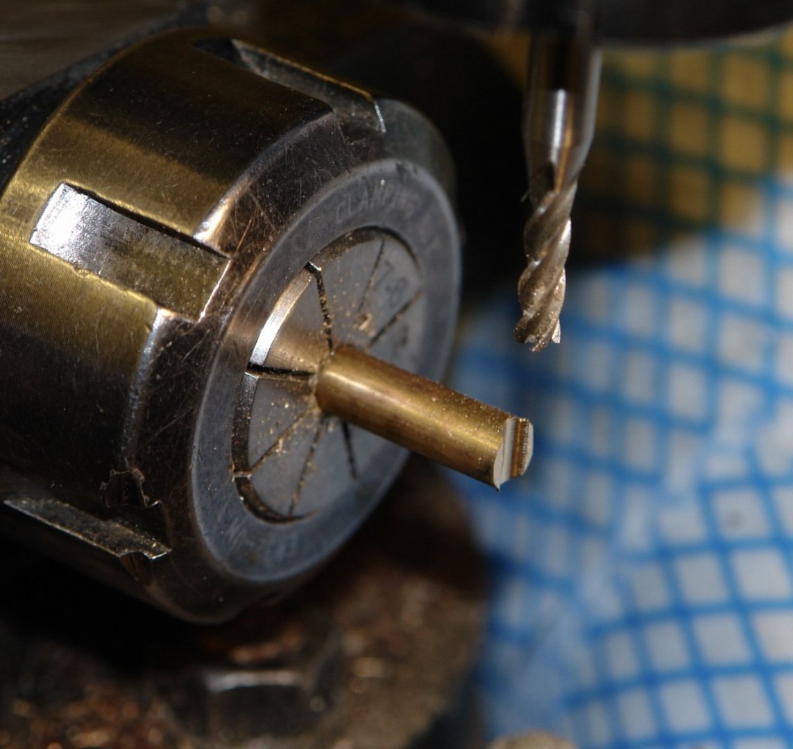
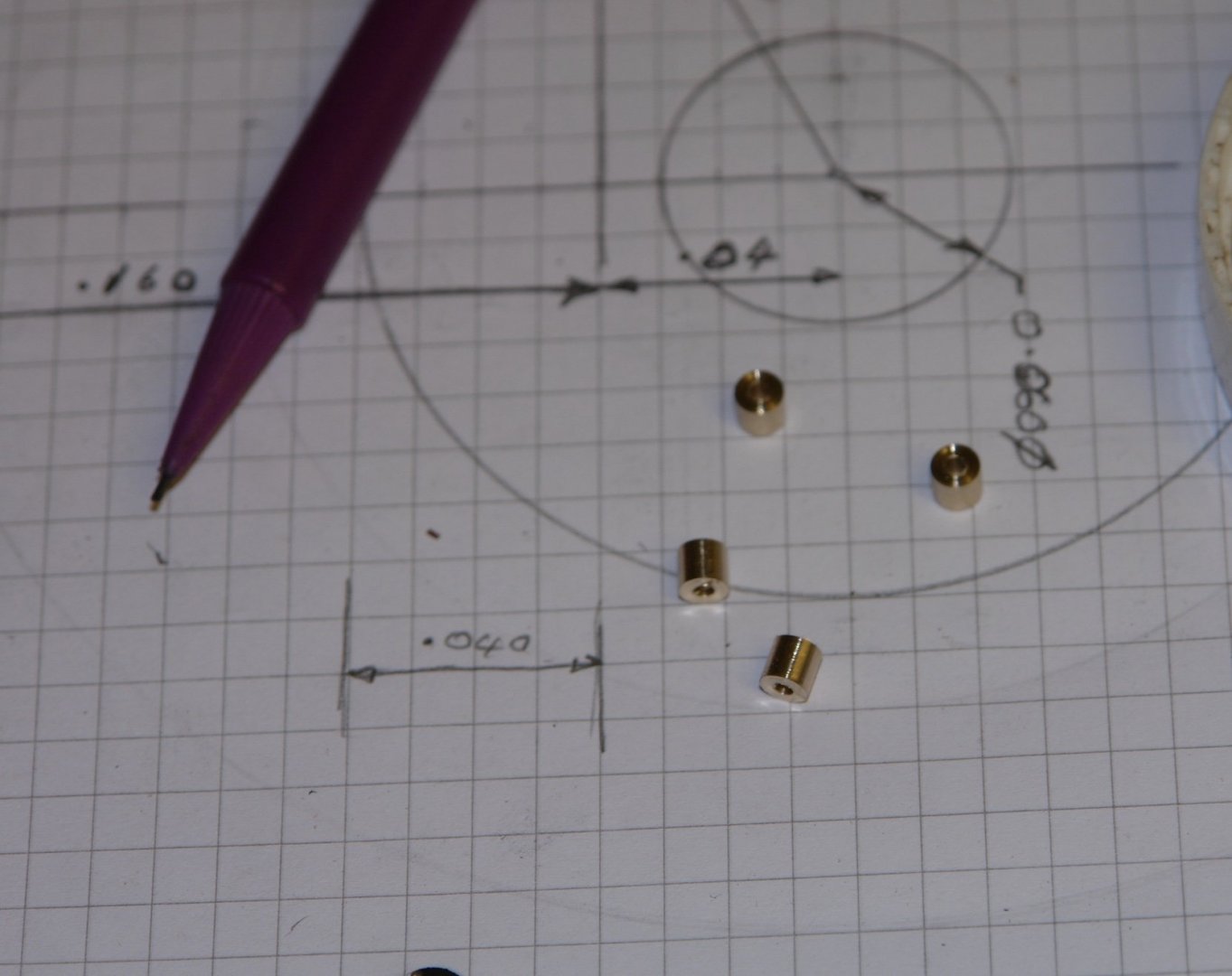
Back to the build after the shock absorber discussion. Thank you for all the comments and thumbs ups. I realise I didn't post any images of the finished rails ( after 4 coats of poly). Having completed the rail I decided to make and mount the brackets for the shrouds - 4 each side for the main and foremasts - 16 in total. Similar brackets also attach blocks to the rail - 4 for each mast - 8 in total. I therefore needed 24 brackets. I started with a sketch. The brackets are fairly simple affairs:- I drilled a piece of brass to create the holes and then used these holes as a reference to mill the outer radius. A slitting saw was then used to divide each bracket. The "comb" was then turned horizontal and a further slitting saw cut was used to separate the "fingers". I then needed to attach a spigot ready for attachment to the rail. This involved drilling a .04" hole along the axis of the bracket. To do this i made a simple holding jig - basically a "U" shaped notch .05" deep in a piece of scrap aluminium. The jig allowed the brackets to be positioned accurately and repeatably in the mill to allow the .04" hole to be drilled. With all the drilling done .04" wire was glued in the holes to create the spigot. Finally another simple jig was used to part off the spigots to length. I now have 24 ready to install.


-
Bob - I would agree that these shock absorbers are unlikely to be of a lot of use in and uncontrolled jibe. I once sailed on Simon Le Bons yacht "Drum" (fortunately not at the time she lost her keel). At the time she had huge plates welded on to either side of the main boom to repair the damage caused by an uncontrolled jibe. According to there skipper the jibe had bent the boom through about 45 degrees - remarkable given its very ample section. However it is my experience that even a controlled jibe in inclement weather can lead to boom whipping across until restricted by the main sheet. Under these circumstances both rubber and spring types of absorber will act to mitigate / reduce the instantaneous impact load. The loads on a big yacht can be many tons and ones inability to compress springs by hand is understandable. I agree with you that age hardened rubber wont work and my assumption is that the donuts have a recommended replacement cycle.
-
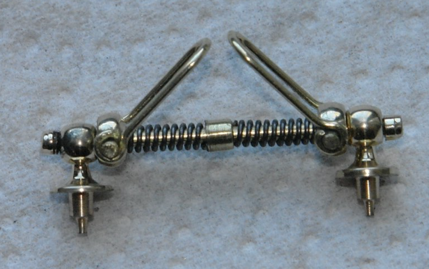
Here is Altair's shock absorber - about 1" long. Bob / Druxey Altair's leather covered blocks are the nicest i have ever seen -
-
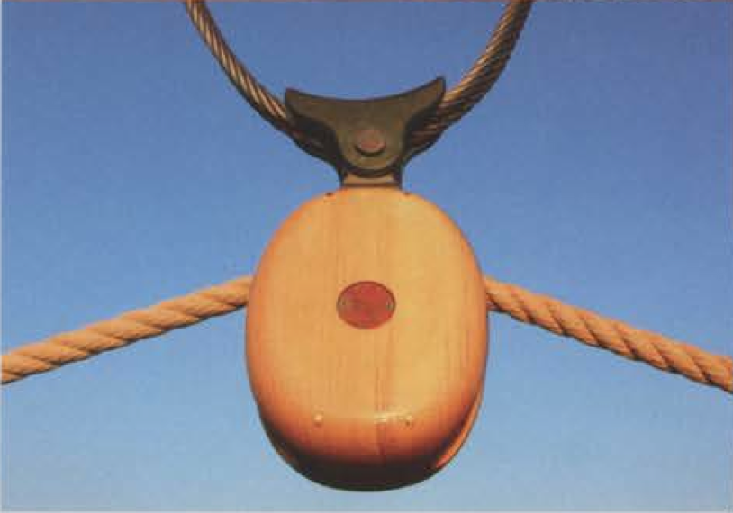
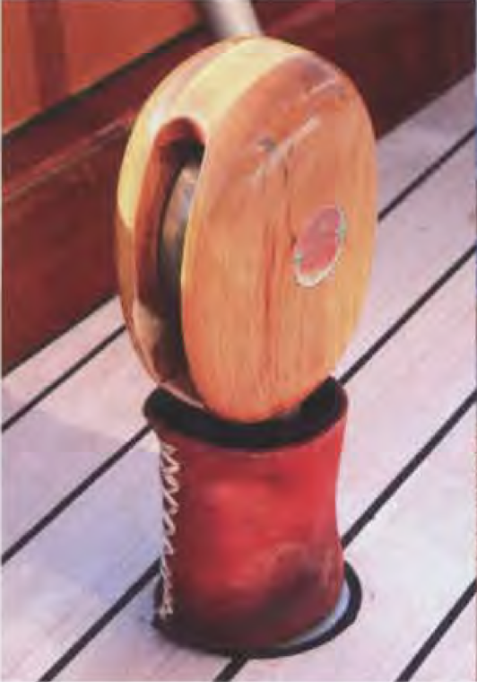
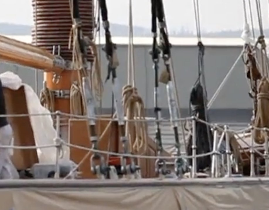
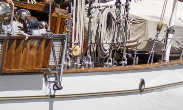
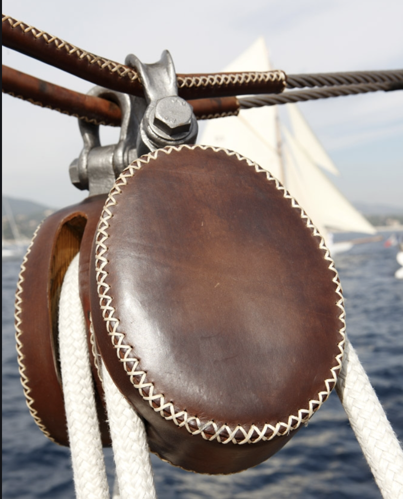
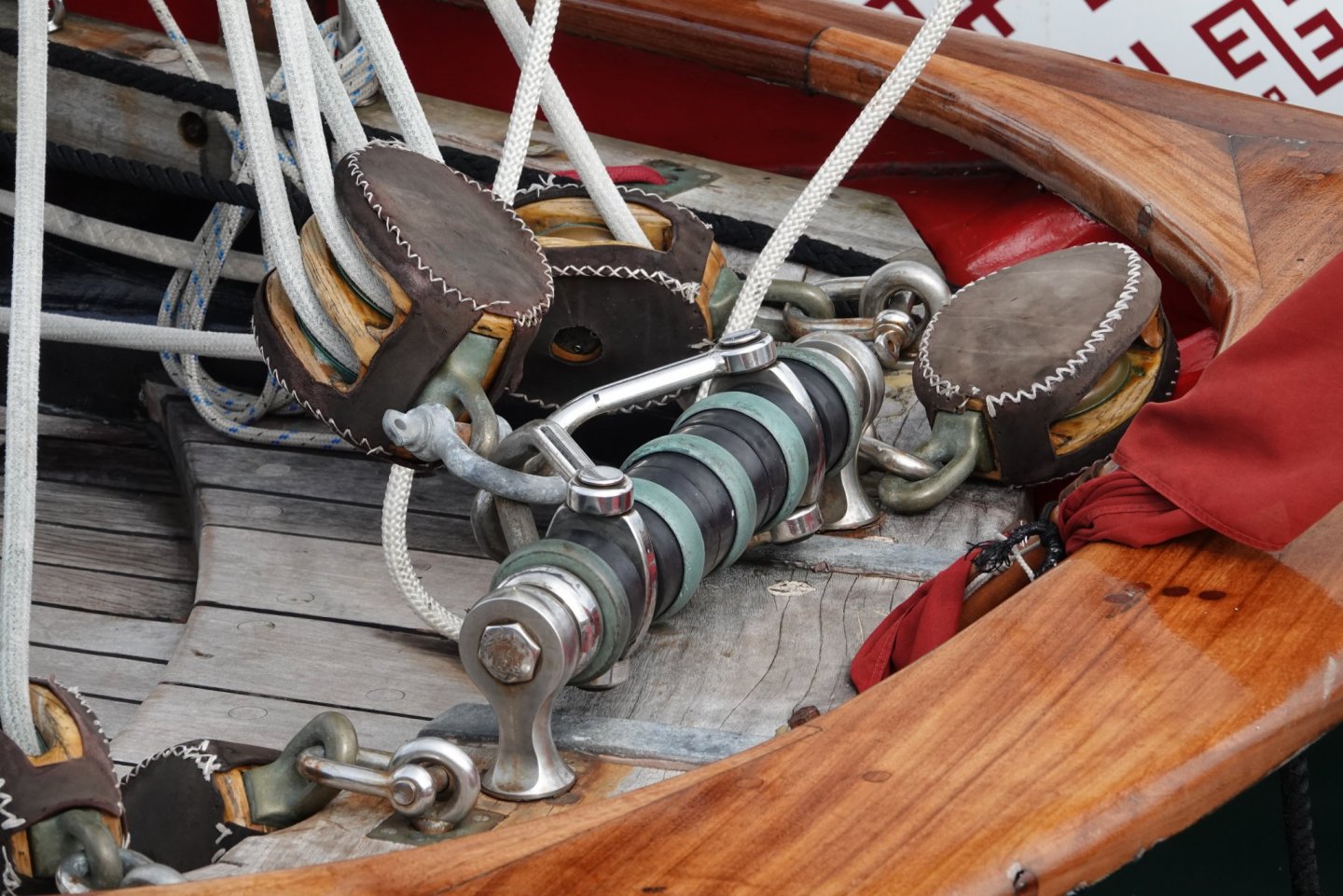
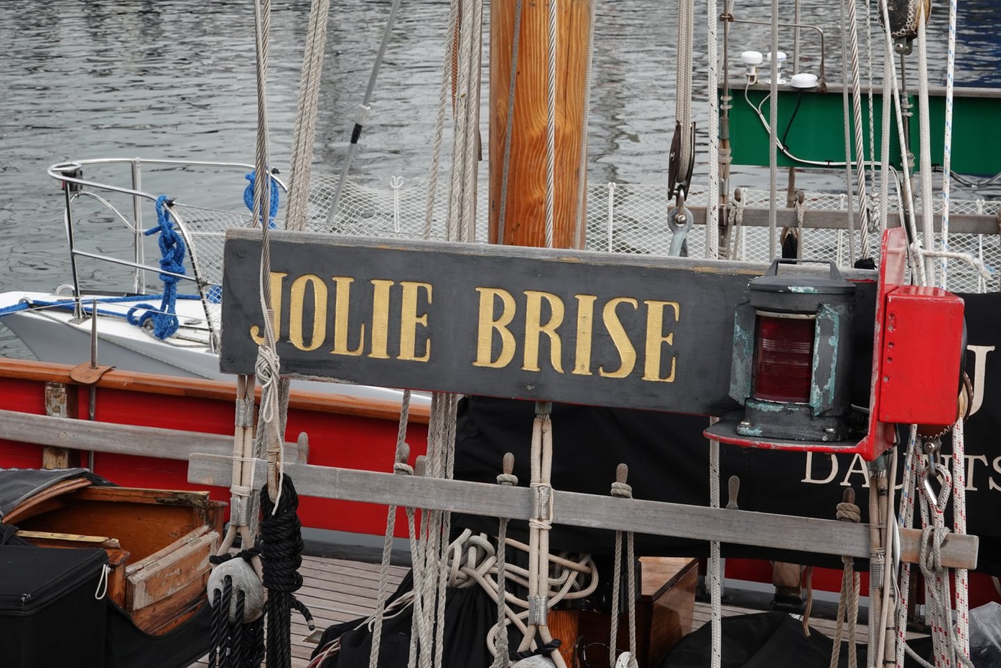
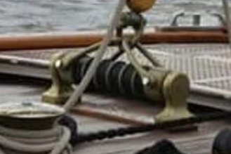
Thank you all for the interesting debate. Just to join in - last summer I was in Lerwick in the Shetland Isles and took the following photographs:- The rubber donut type of shock absorber seems to be a more modern rendition of the shock absorber concept. When I built Altair the plans featured a shock absorber with a coil spring and that is what I modelled. As you can see the Jolie Brise also has leather covered blocks - as did Altair.
-
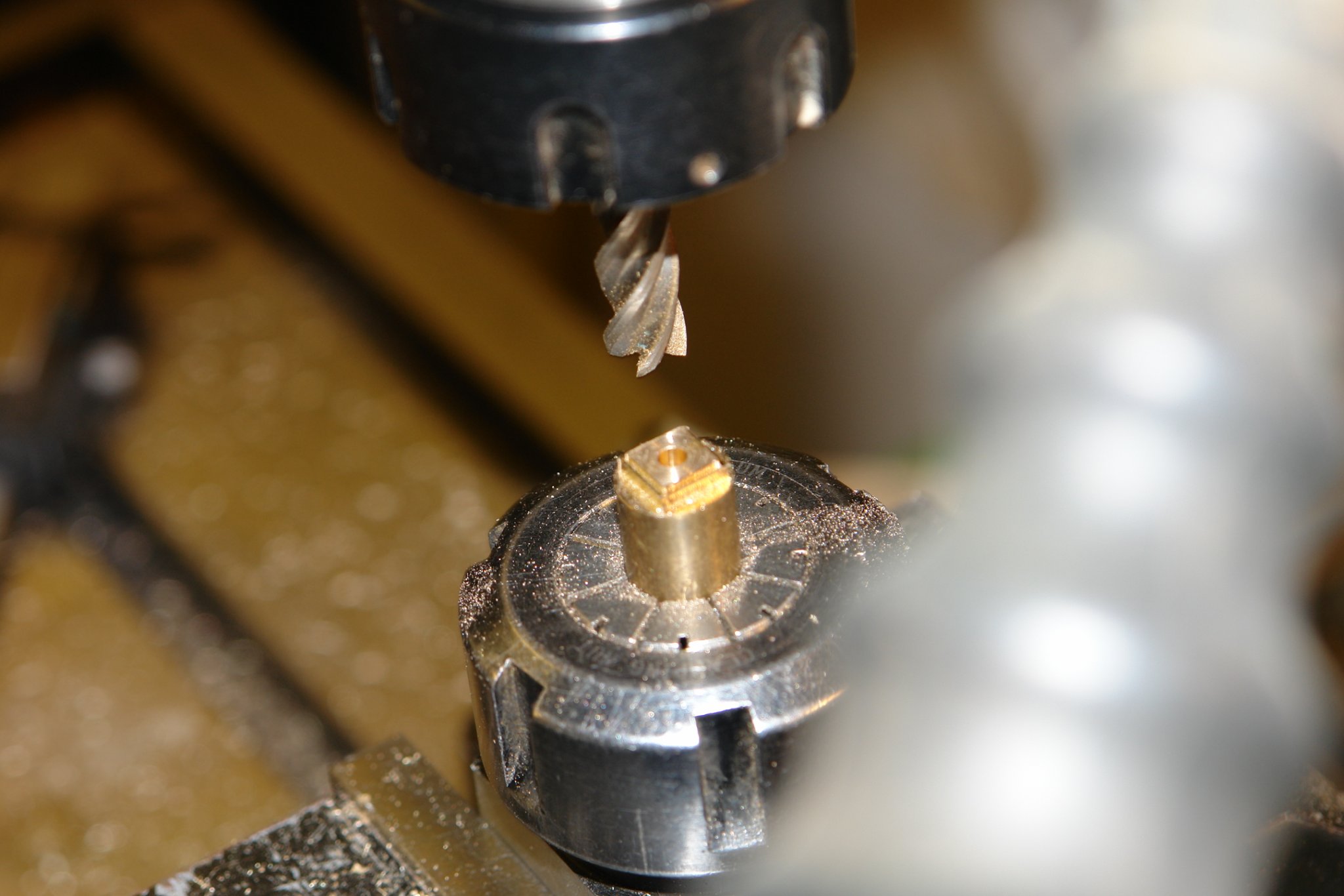
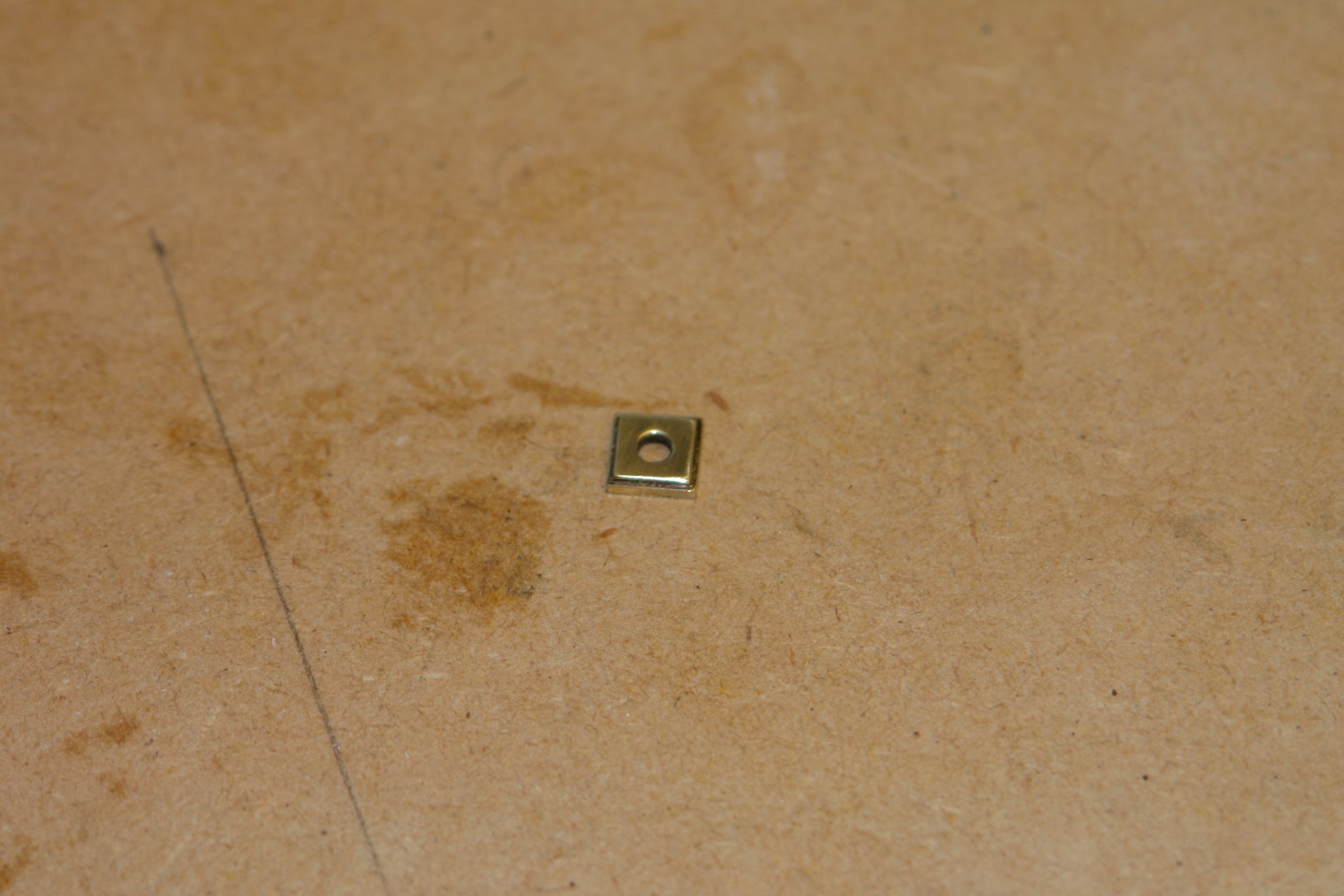
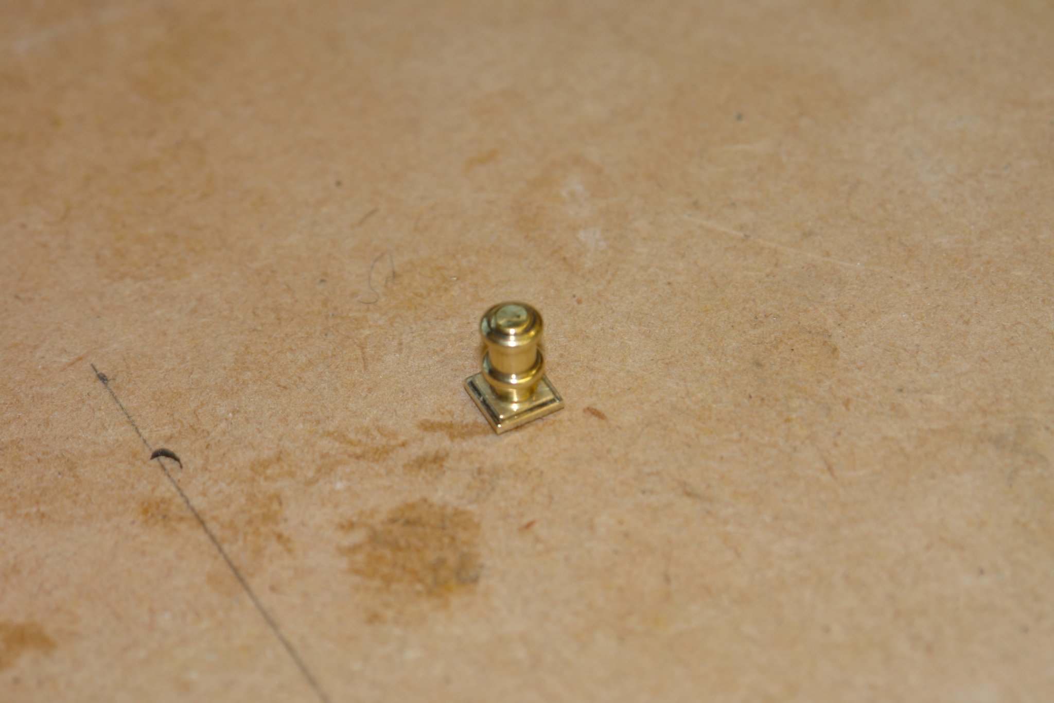
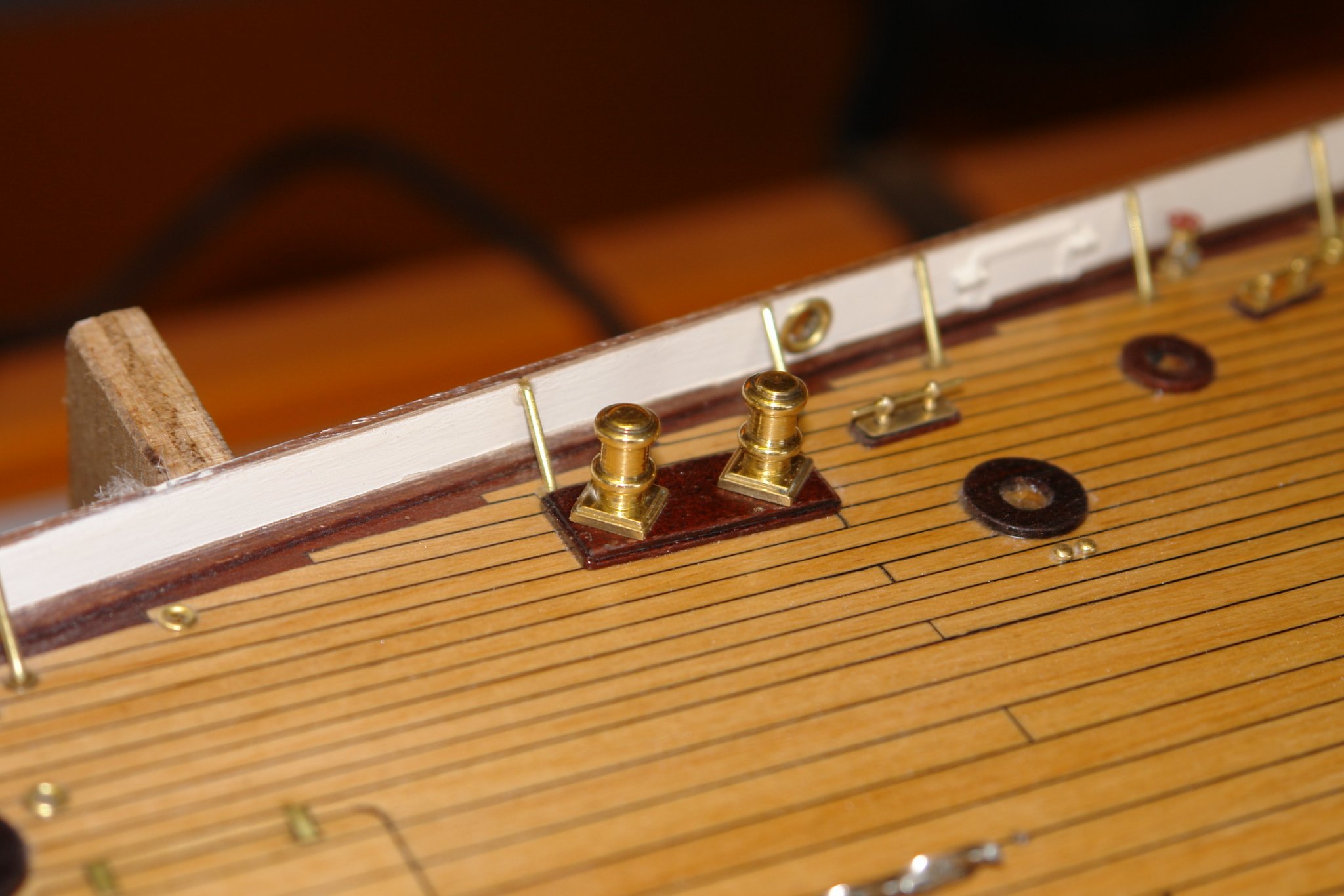
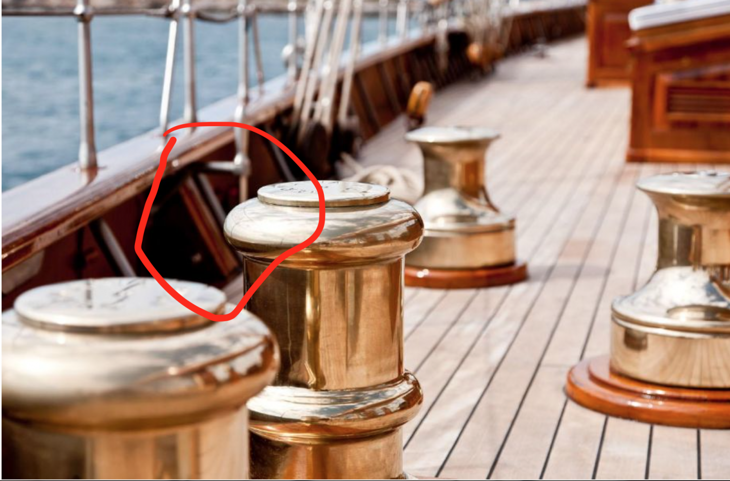
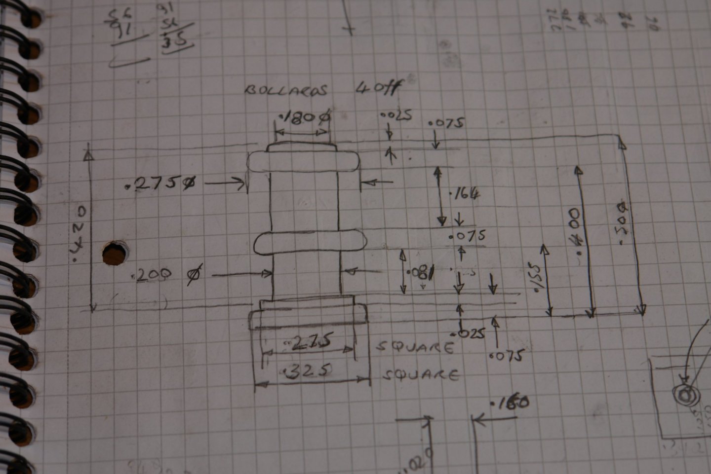
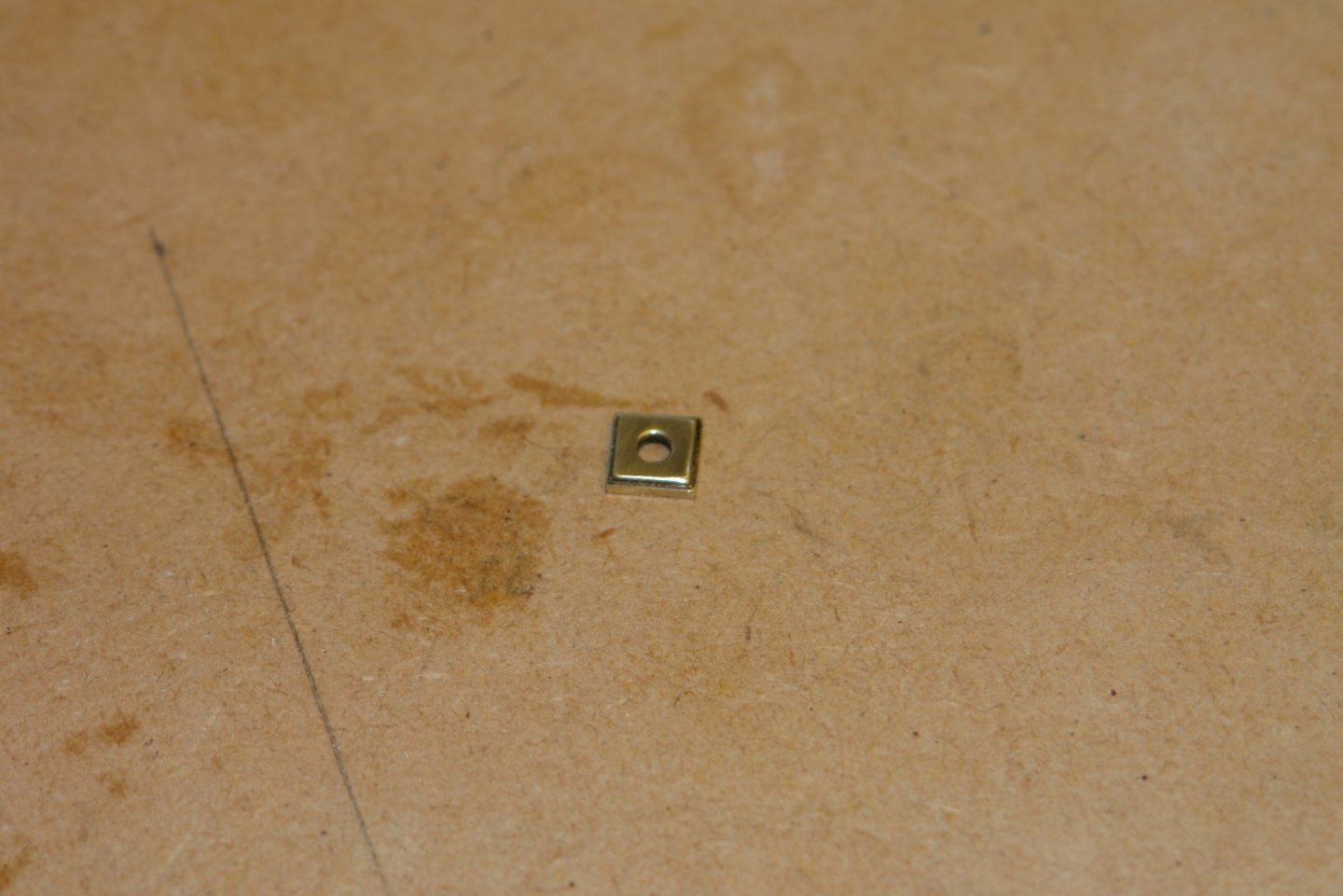
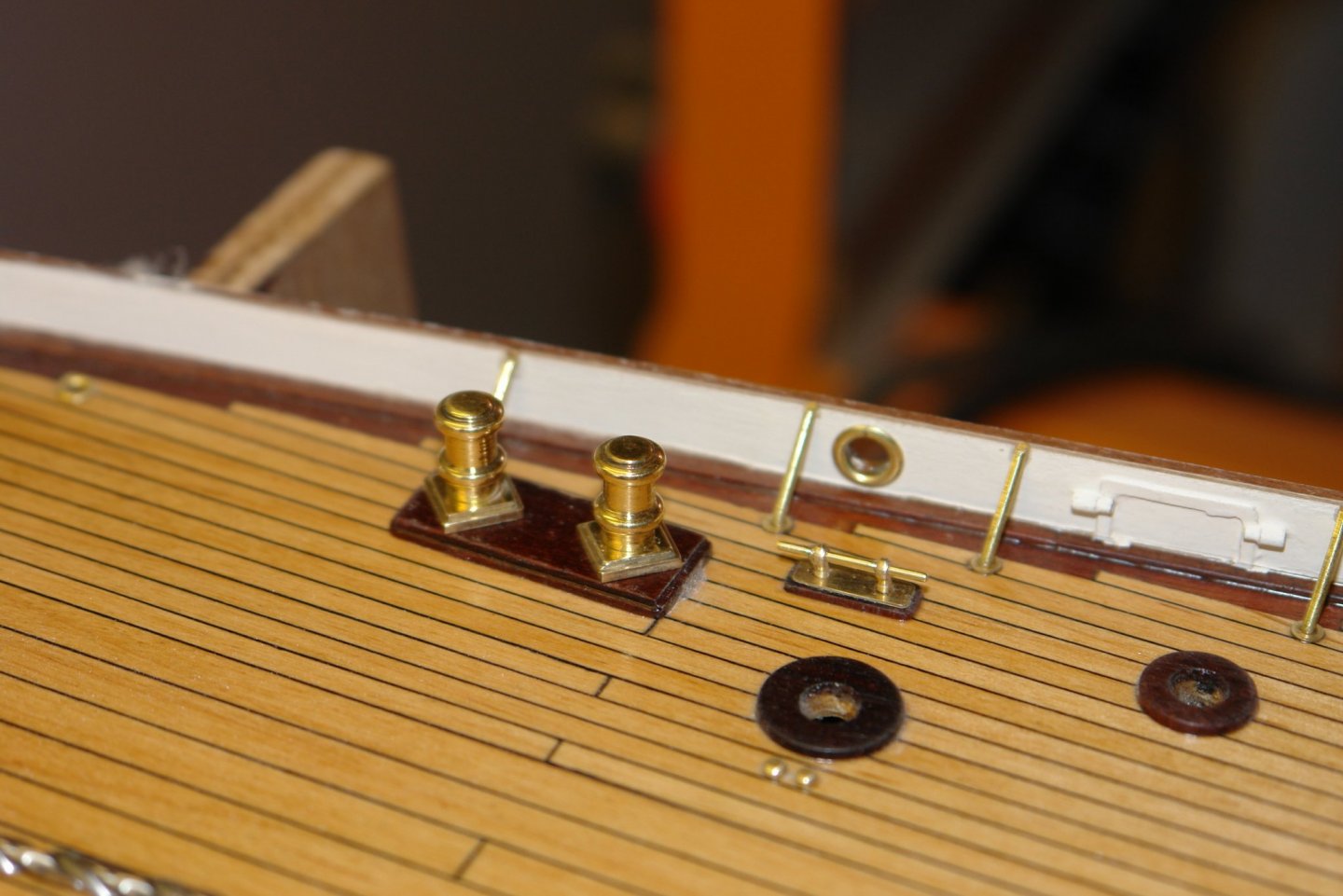
Thank you Gary. We have house guests. They eat my time and progress is slow. I did the small job of finishing the bollards. I made the stems last spring. Only the square bases remained and these were milled using the square collet block. I glued them on to the previously glued plinths.


-
Magnificent tin bashing Kees. Very skilful. What is the thickness of the brass sheet you are working with?
- 193 replies
-
- 2
-

-
- wilhelmina vii
- fishing
- (and 1 more)
-
Long may it continue.
-
Nicely done - I hope the fires are keeping their distance.
-
Thank you all for the positive comments, and thanks for all the thumbs ups and visits. Keith - As with previous builds I doth think I will bother. The very shiny brass looks a bit unrealistic and I quite like the way it naturally tarnishes as the model ages. It almost gives it a life. I'll be getting on with installing the brass work on the deck over the next week or two and then it will be a suitable time to get post some general views of Germania. Michael - I think collet blocks are a godsend, they make life a lot easier. One of my best workshop buys of recent years. Pat - it is an optical illusion - I didn't include any. 4 of the brackets don't have any and I guess they must be bolted in place from below the deck:- the two on the stern rail have 4 bolts each but I decided I didn't really have enough room at 1/36 scale to get them in. A bit sloppy I know, but I have to draw the line somewhere. Thank you John - you made me laugh out loud.
-
Very clean work Michael. I may be being thick but I didn't quite get how you cut the sloped dado?
-
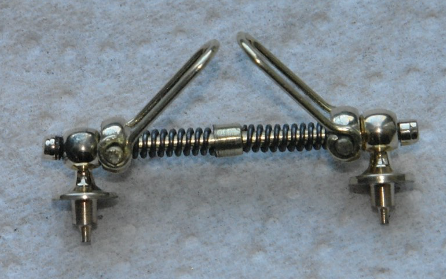
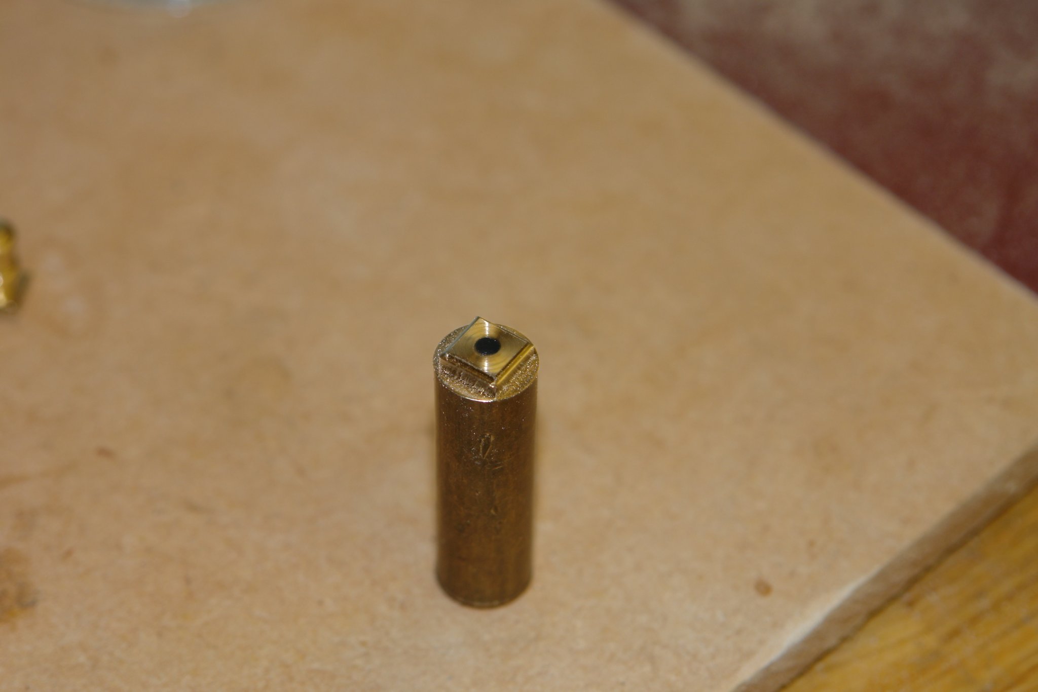
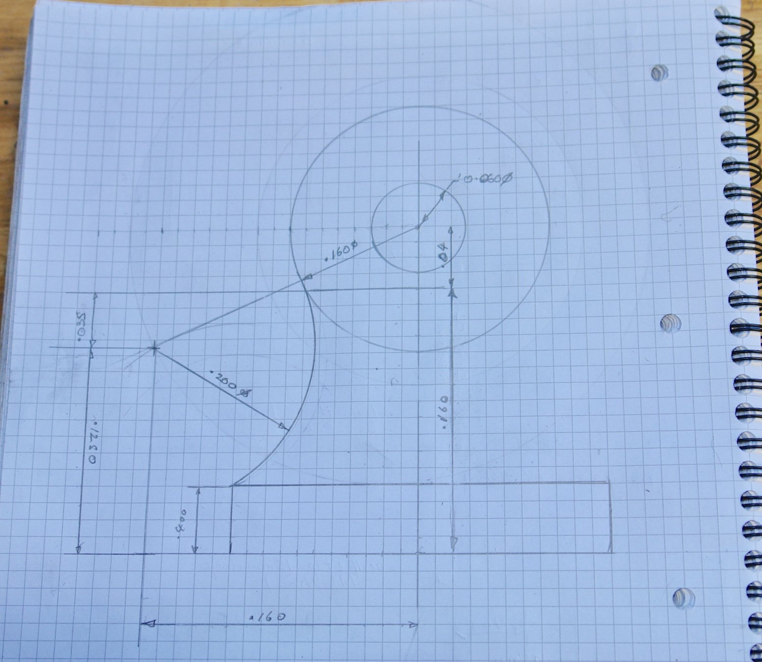
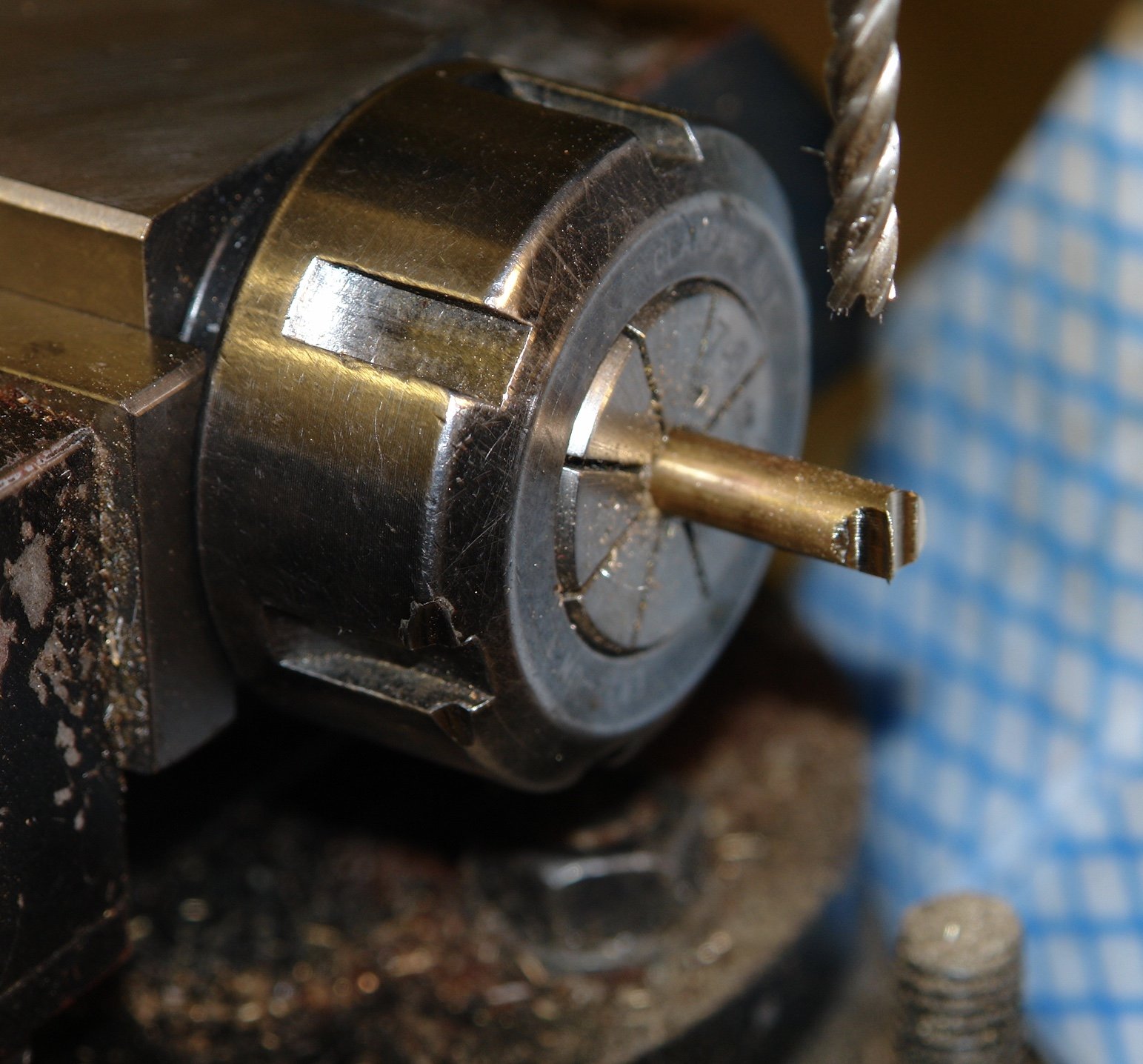
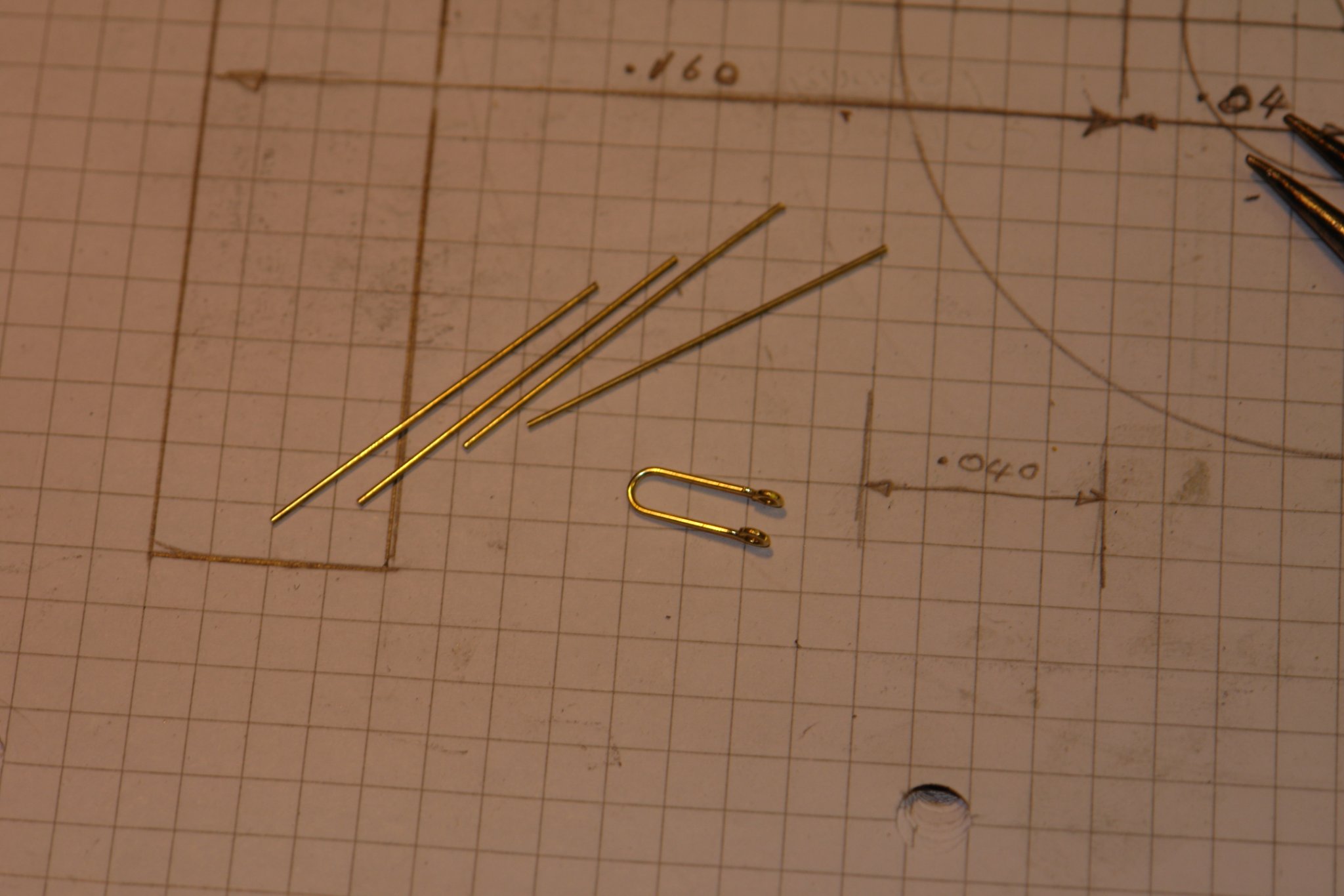
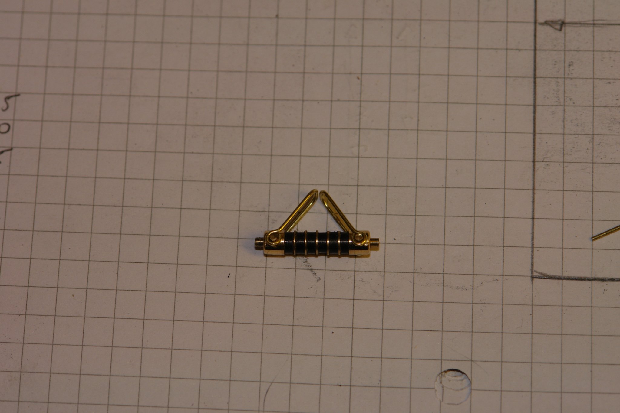
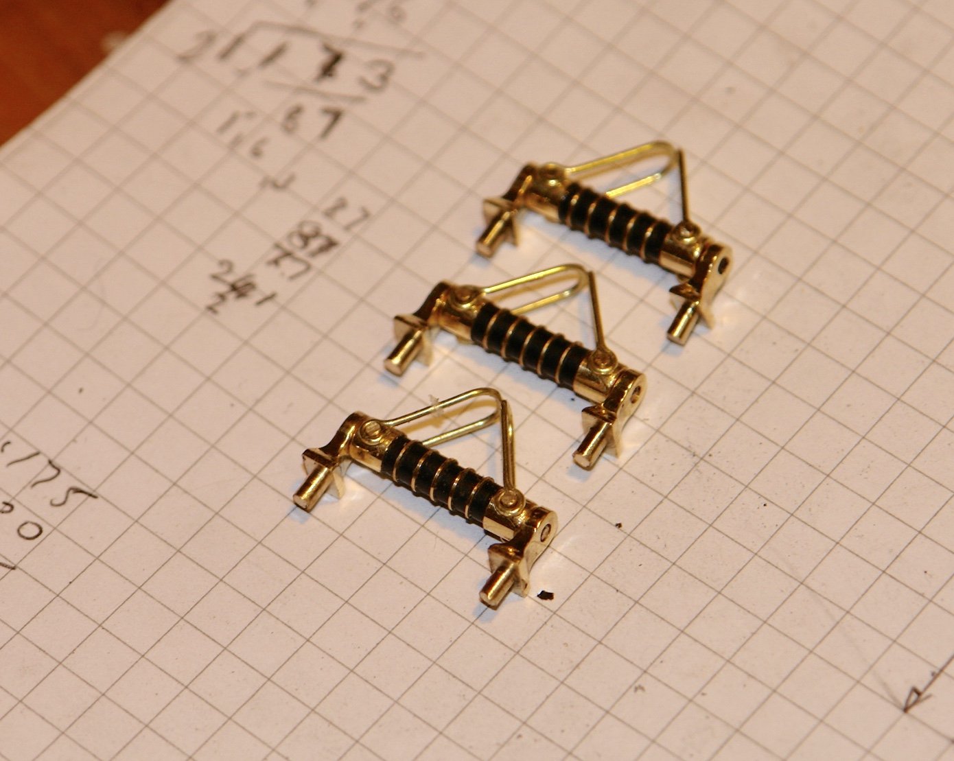
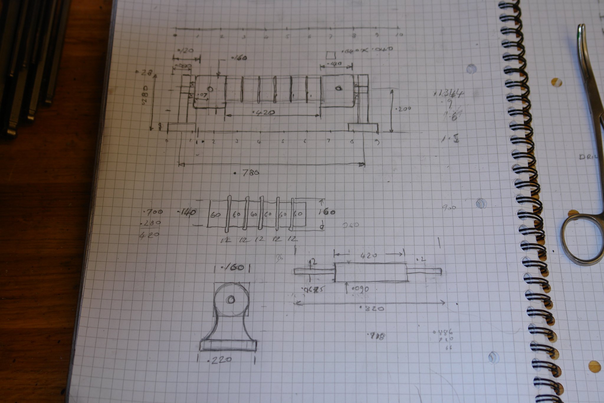
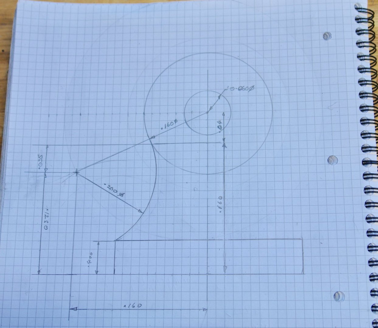
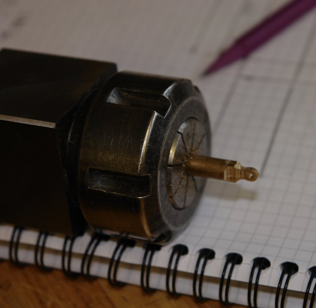
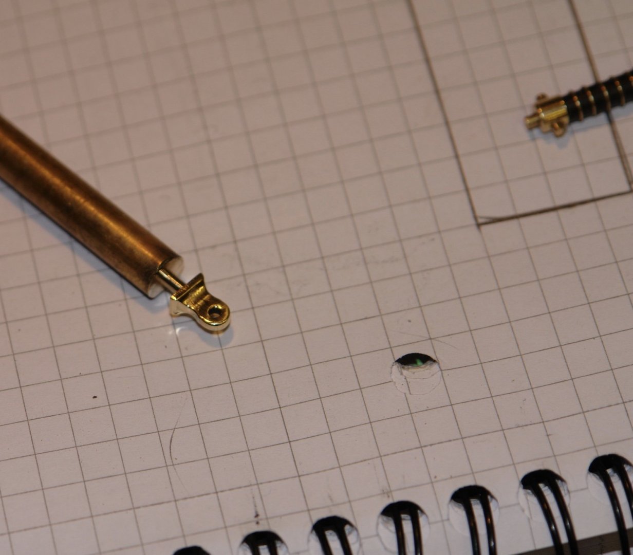
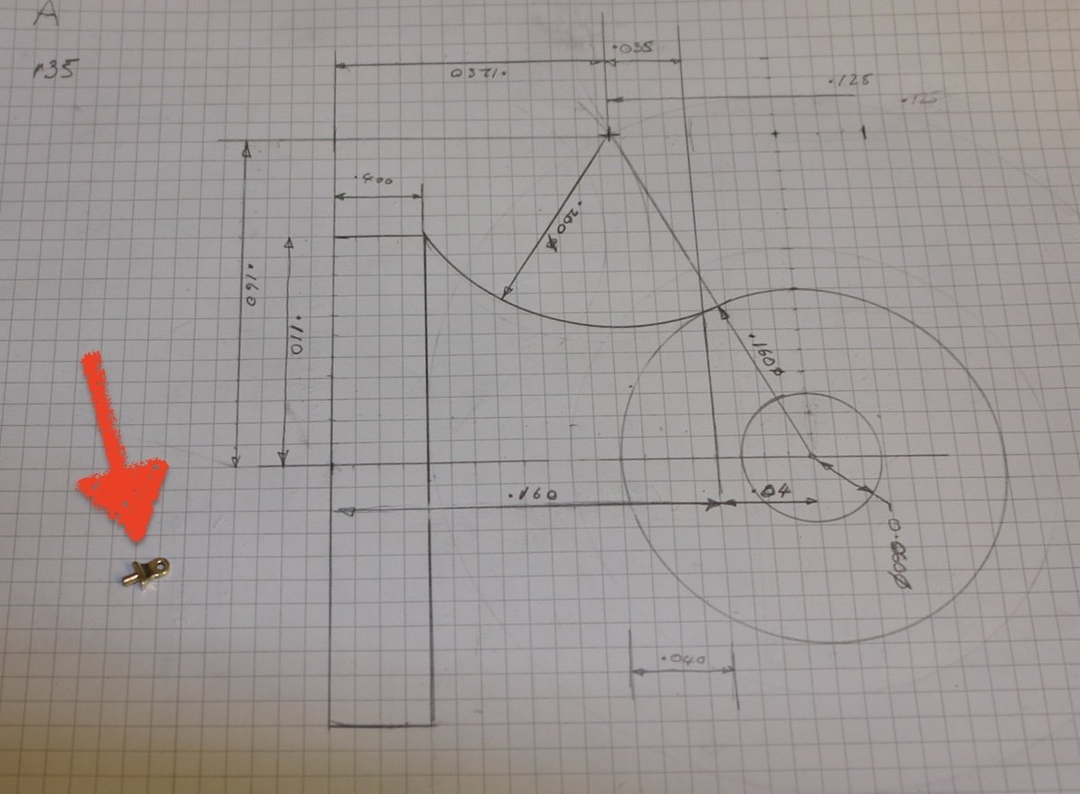
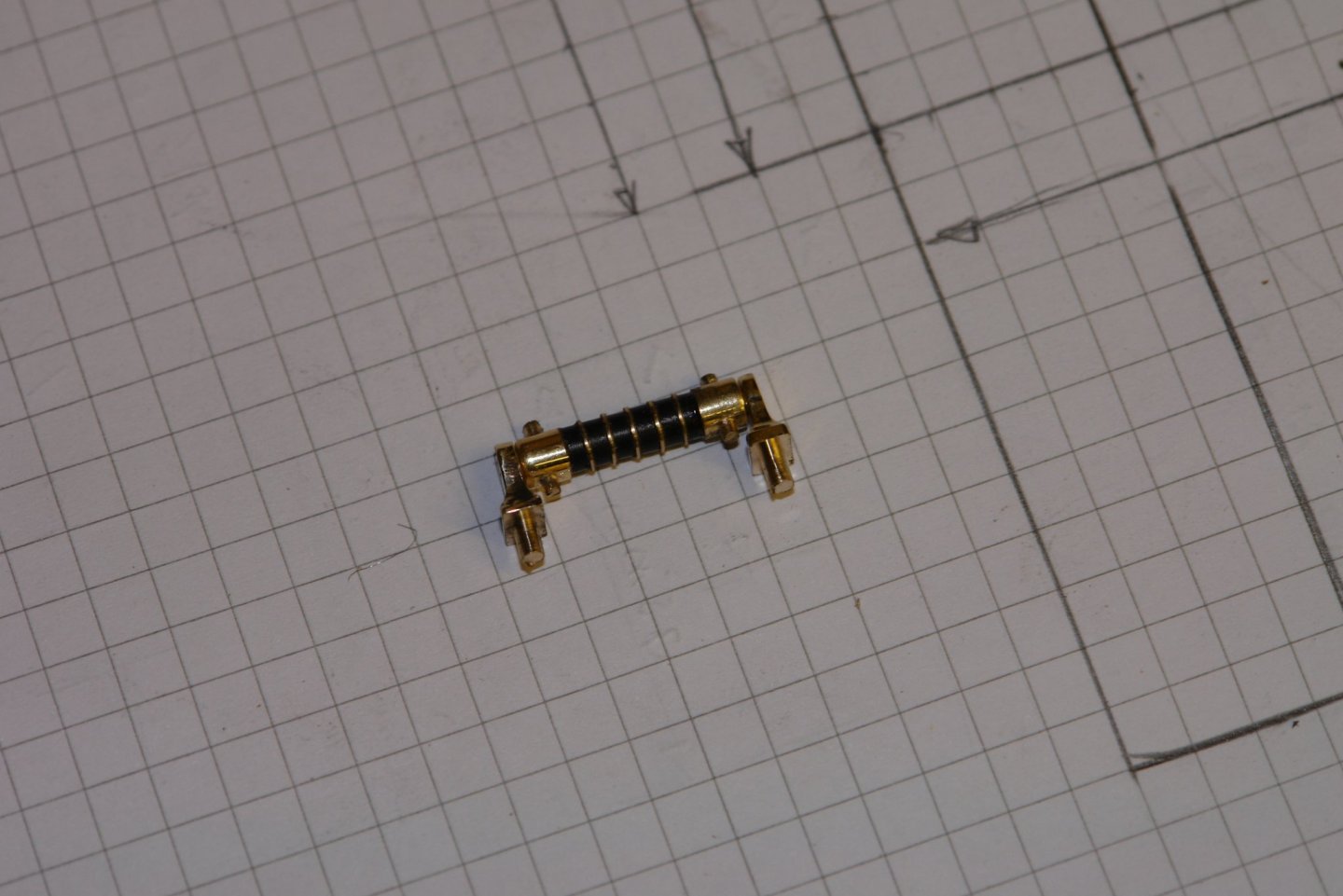
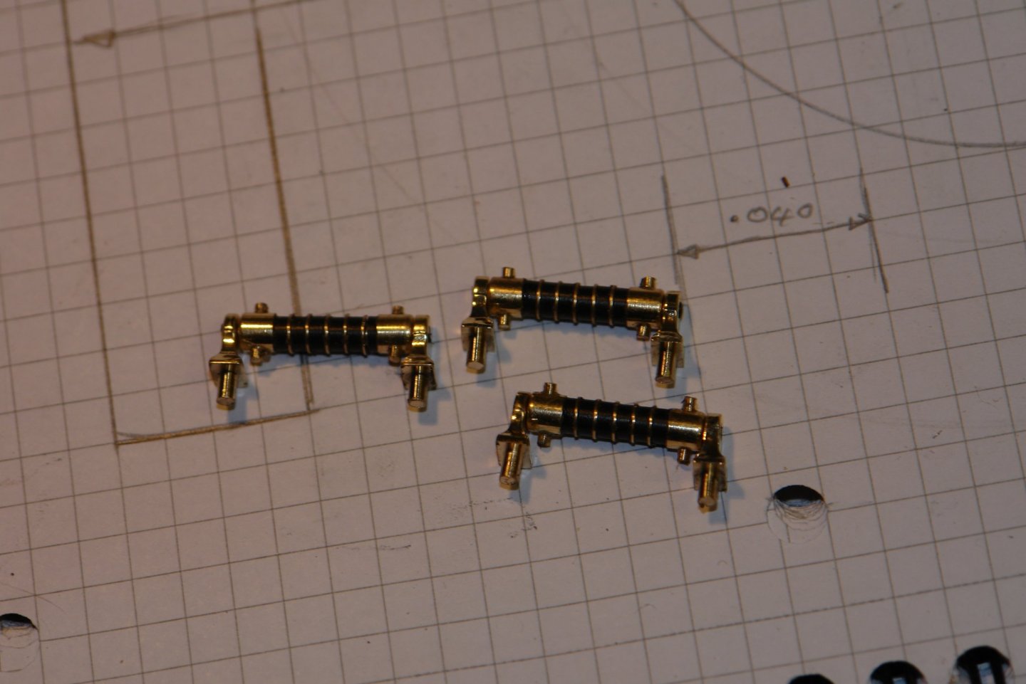
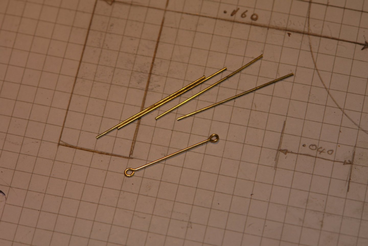
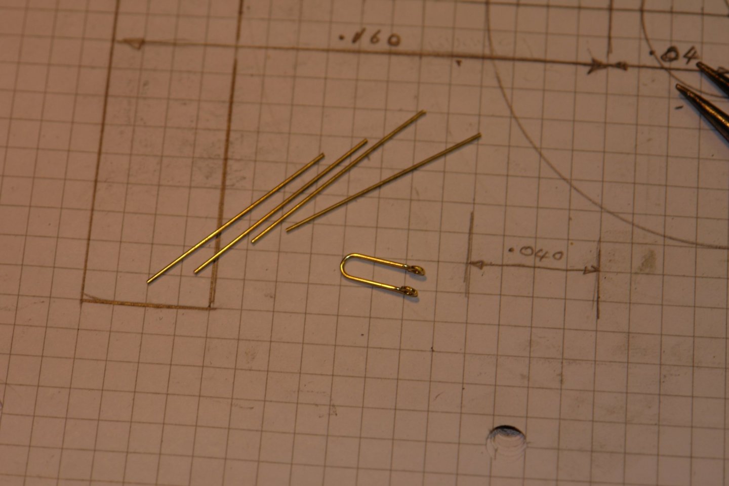
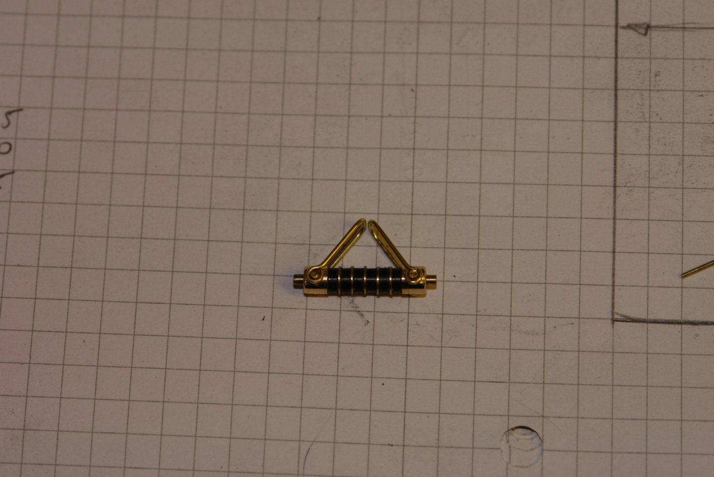
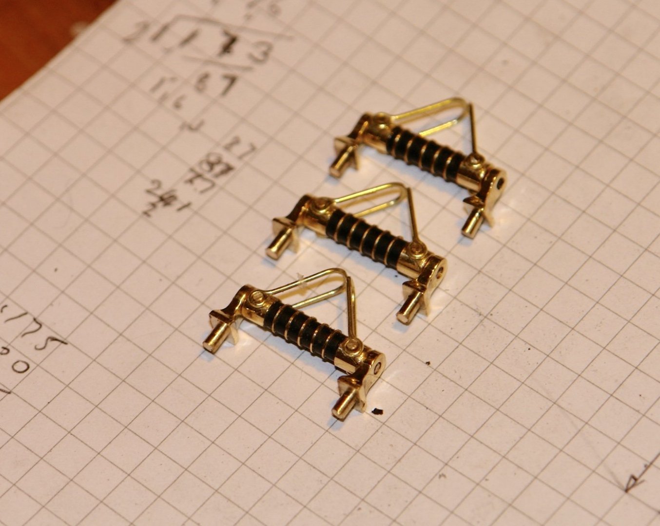
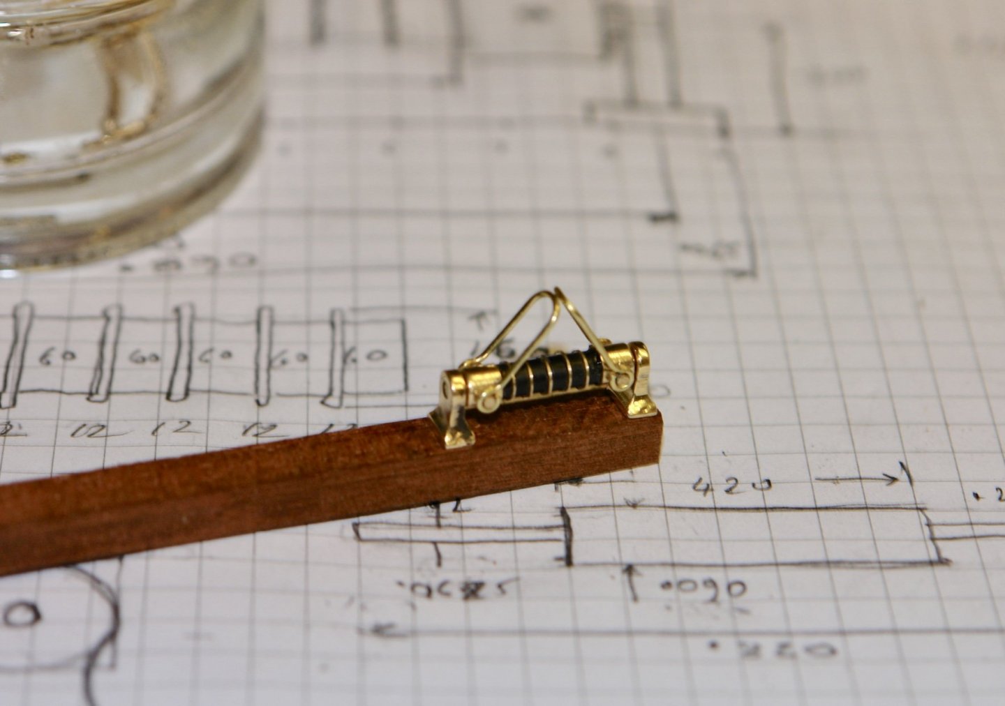
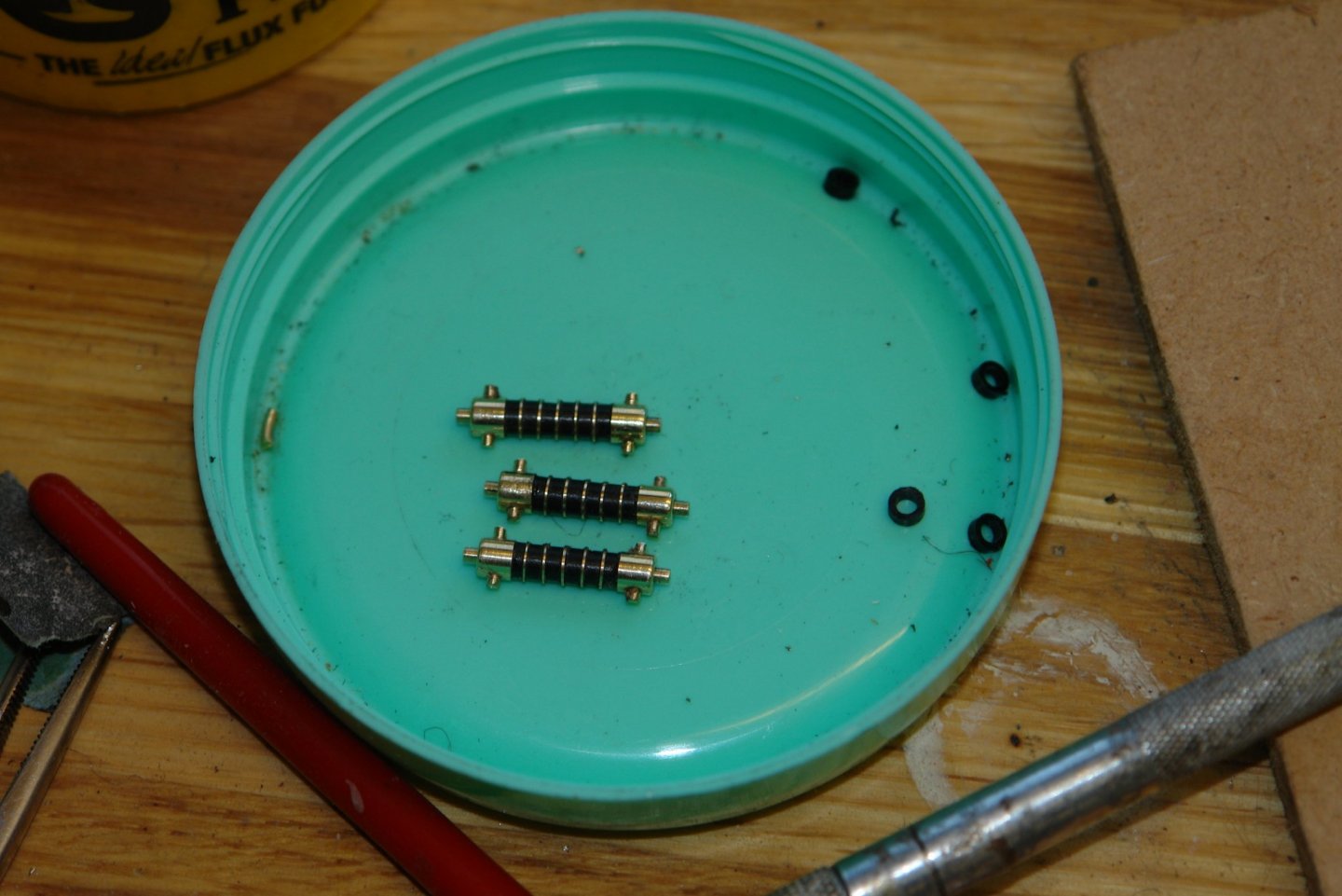
A particularly mild January is making the workshop more inviting. The temperature today hit 13 deg C which felt almost Mediterranean. A few hours each day for 3 days saw the shock absorbers completed. The mounting brackets for the shock absorbers are formed from a series of curved and flat surfaces and I thought it would be nice to reproduce the form. I had a good ponder on the best approach and in the end decided it would be better to make each bracket in 2 parts consisting of the boss and the base. I started with a large scale sketch. I drew it accurately because I needed to be precise about the centres of the curves. I then got on with the manufacture of the base. I took a 1/4" brass rod and mounted it in a square collet chuck. This was placed in the mill vice and centred on the cutter. A 0.160" diameter cutter was then used to plunge cut the end. The x and y axis were then reset in accordance with the drawing and a 0.200" diameter cutter was used to plunge cut either side of the bar. The bosses were then turned on the lathe. The next step was to join the 2 parts using soft solder. This was done without removing the rod from the collet block. It was then back to the mill where the final shaping was done with the side of a 0.160" diameter end mill. The rod was then removed from the collet bock and mounted in the lathe. A locating spigot was then turned. Followed by a bit of polishing. The brackets are somewhat smaller than the sketch. I then mated the brackets with the shock absorber to see what they looked like. The next step was to make the shackles - this involved a bit of precision bending. The wire is 1/32" diameter. I made all 6 and attached them to the pegs on the shock absorbers. The spring in the wire holds them quite securely and they function as required. I then checked what they would look like on the plinths. Satisfied with progress I have stopped for the day.


-
Newbie starting with J-Class Endeavour
KeithAug replied to Sananda's topic in New member Introductions
Sananda, Welcome. You will find a number of build logs for Endeavour if you use the search facility. I built one a few years ago (link below my name) and if you need help don't hesitate to ask. A build log is the best way of getting advice from a wide range of excellent builders. Good luck. -
Nice method on the yolk Bedford. I hope the winds are kind and blow away from you.
-
Coming along nicely Michael. I have that model of exacto razor saw, but mine only dates from 1990. I am on my second blade though. I like the fence - I hadn't tought of doing that but will in future.
-
I agree with Michael, is is hard to tell wether I am looking at a model or the real thing. Excellent workmanship GL.
-
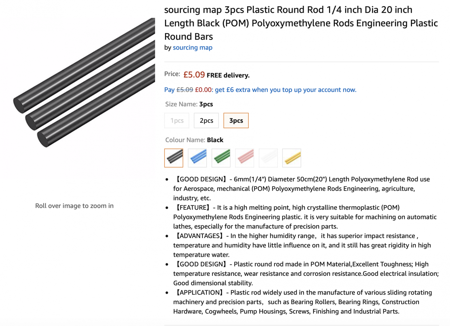
Michael -When I rechecked I realise I bought it from Amazon - not eBay. I was really surprised how cleanly it cut and how nice the turned finish was. It is Polyoxymethylene, more commonly called acetal, polyacetal and polyformaldehyde. it is an engineering thermoplastic and is used in precision parts requiring high stiffness, low friction and good dimensional stability. It comes in a range of colours and diameters. Hubert / Mark - thank you for your kind comments, I do appreciate them. Also thank you to all of you who have visited and or liked my work.
-
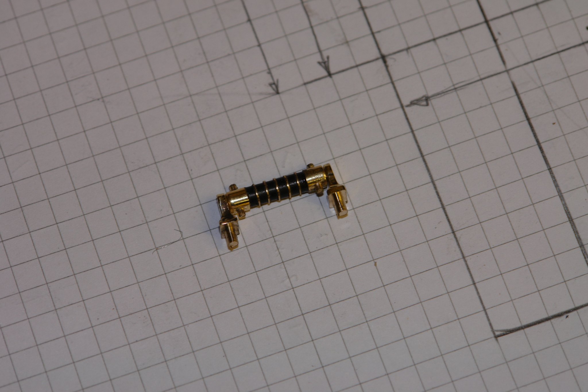
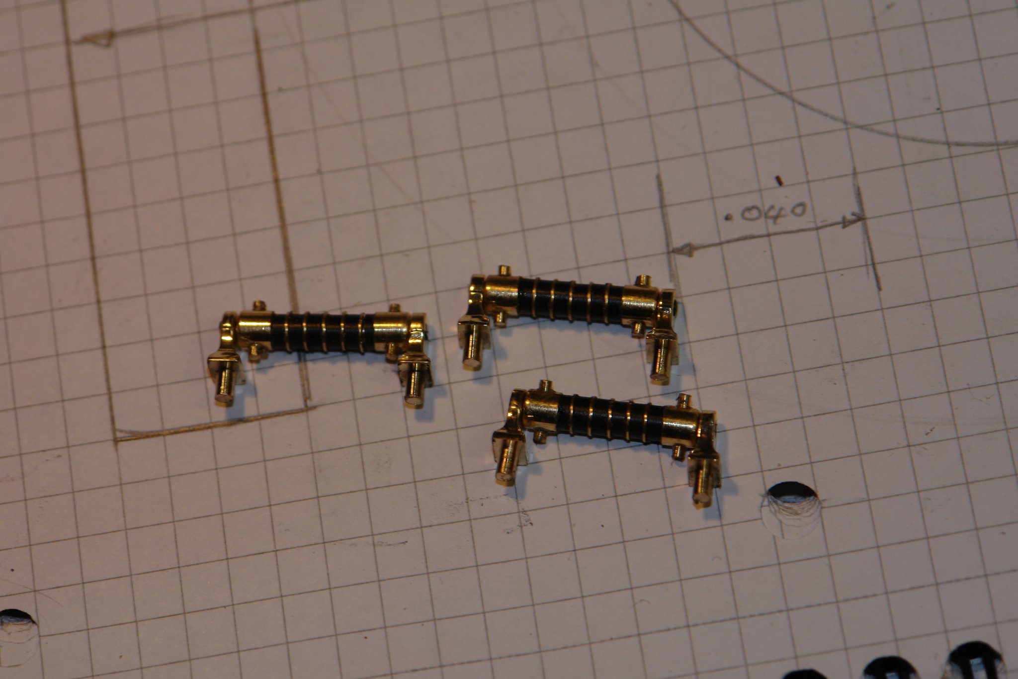
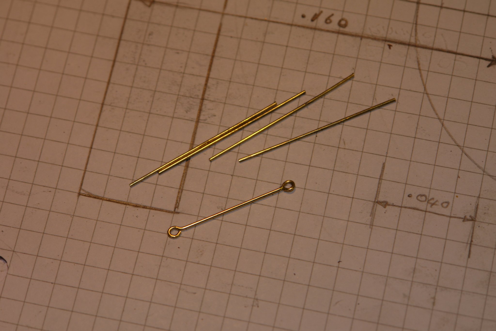
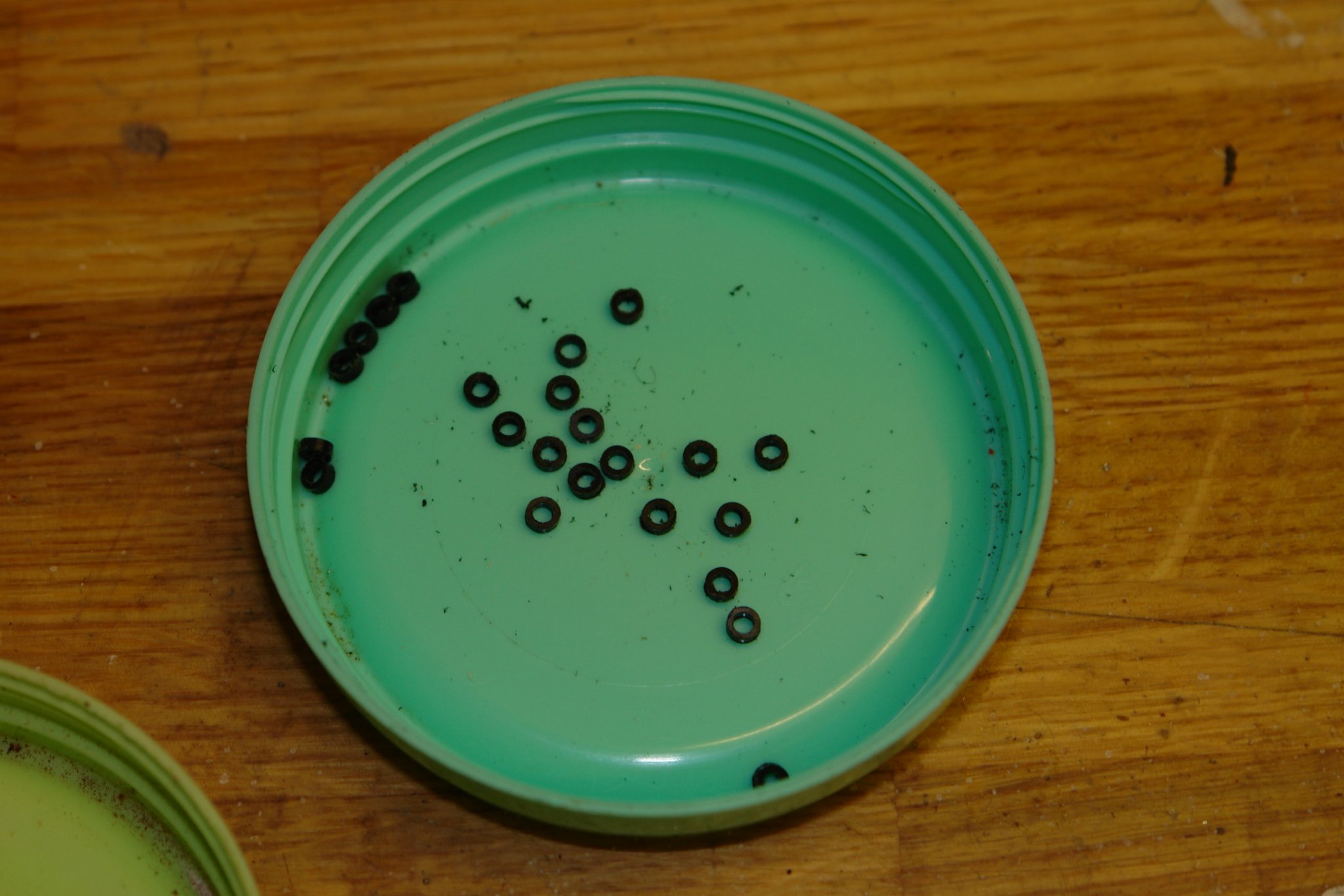
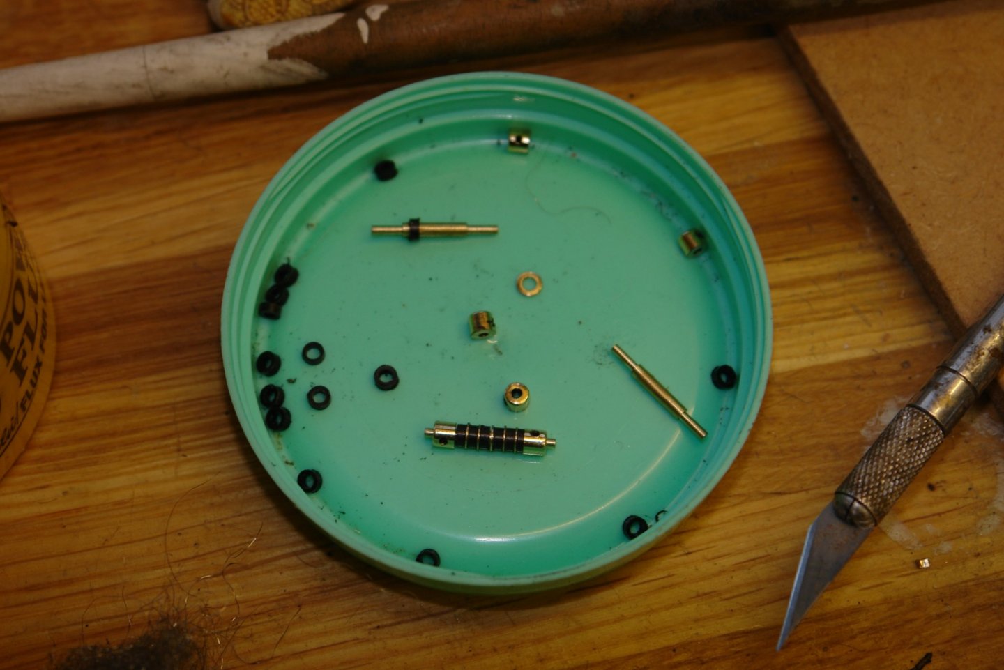
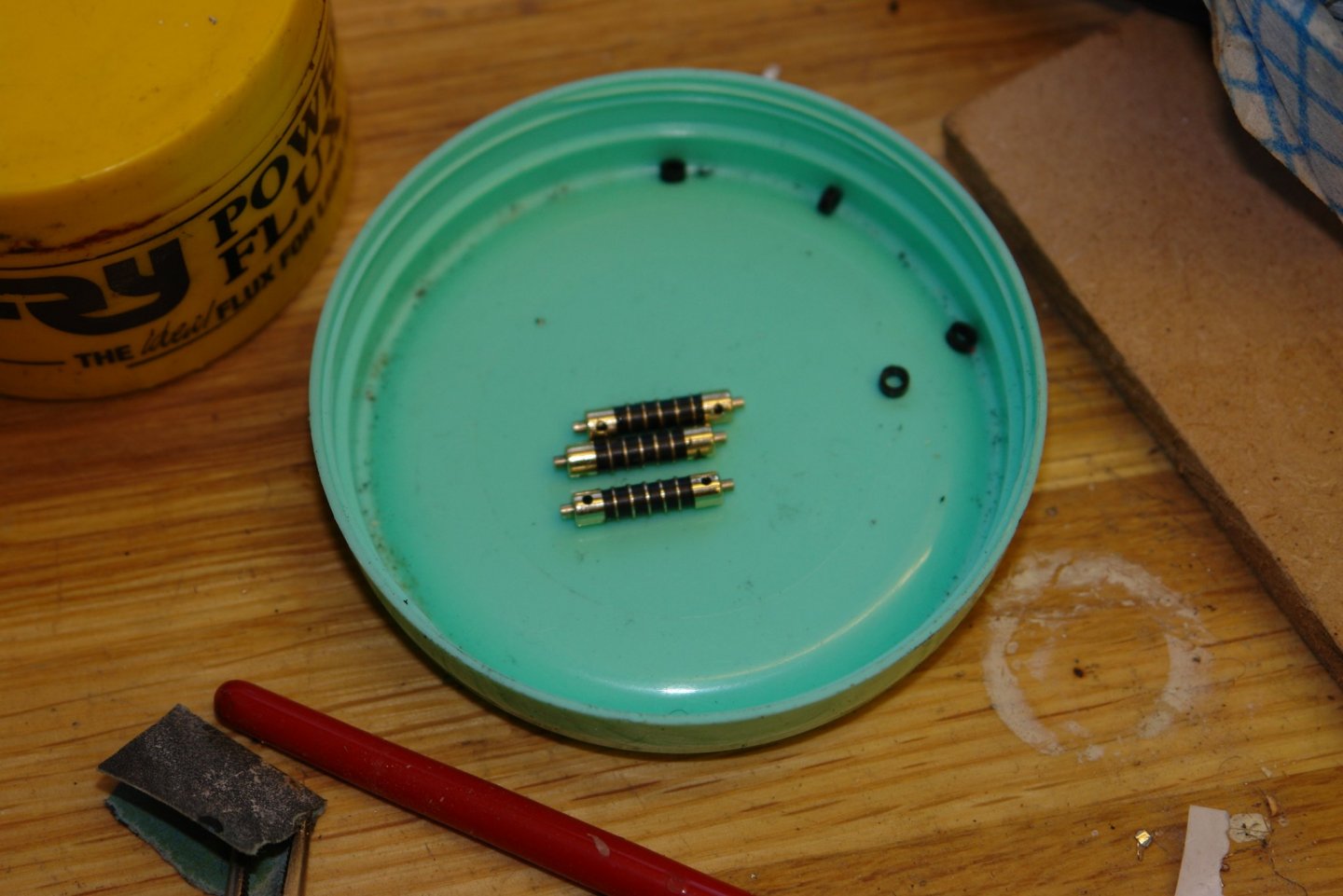
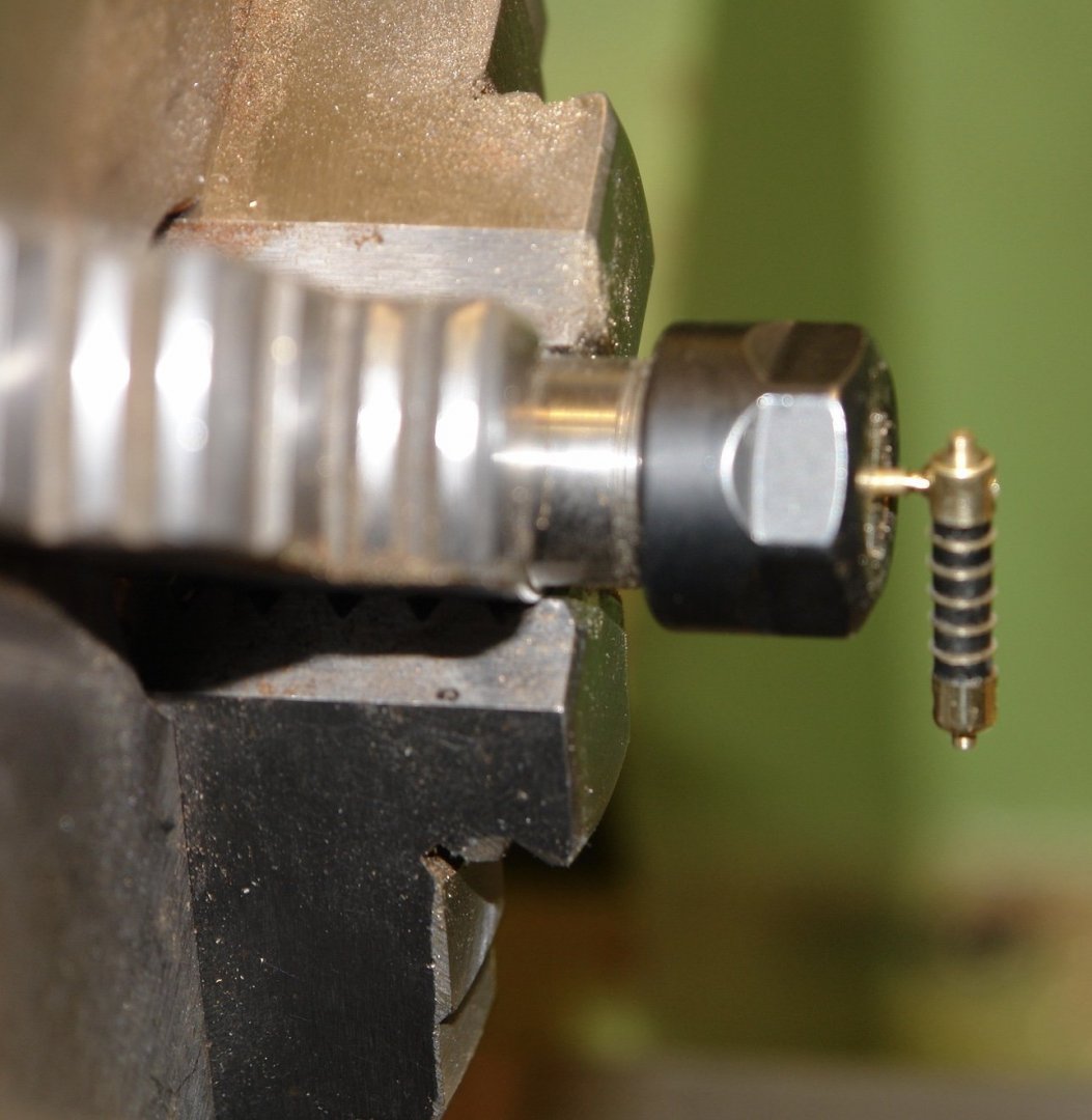
Thank you Michael and Pat. I made a start on the shock absorbers - starting with a sketch. Each shock absorber is made from 22 components as follows;- Rubber donuts - 6 Brass donut spacers - 5 shaft - 1 Fixing brackets - 2 Shackles -2 Shackle boss - 2 Shackle pegs - 4 Quite a lot to pack into a small space. I bought some black plastic rod from eBay which machined very well. From this I made the rubber donuts. These were turned as a tube on the lathe and then parted off to length (.060") using the circular saw. They tended to turn out a couple of thou over and were taken back to size using 600 grit wet and dry paper. The brass spacers were similarly turned but in this case they were parted off on the lathe. As the spacers were only .010" thick the parting tool had to be very sharp to avoid distortion. The shafts were turned from 3/32" rod. The shackle bosses were made from 3/16 rod. The shackle peg holes were cross drilled on the mill before the bosses were made on the lathe. It took a few hours to make up 3. The spare donuts were intentional - but in the end not required. To get the shackle pegs a consistent length I turned them and formed a shoulder on the lathe. I then glued the pegs in place and cut off the peg at the shoulder using a jewellers saw. And that is as far as I have got at present.


-
Very nice work Kees. Its good to see you back in the shipyard.
- 193 replies
-
- 2
-
-
- wilhelmina vii
- fishing
- (and 1 more)