HOLIDAY DONATION DRIVE - SUPPORT MSW - DO YOUR PART TO KEEP THIS GREAT FORUM GOING! (Only 44 donations so far out of 49,000 members - C'mon guys!)
×


KeithAug
-
Posts
3,957 -
Joined
-
Last visited
Content Type
Profiles
Forums
Gallery
Events
Everything posted by KeithAug
-
 Thank you Richard. I had a good look round the internet but they don't seem to be available over this side of the pond - pity really.
 -
Richard, nice diamond file set. Where did you get them please?
-
You are a glutton for punishment Phil. So many small and detailed guns, I admire your dedication.
-
Superb work on the mouldings Richard. Have you considered scratch building?
-
Yes Steve that's how I work. "Only a few to do so I will short cut it". When I am done I usually look back and think it would have been simpler and quicker to do it by the approved method. I actually break more micro dills by dropping them a few inches on to the milling table than by drilling with them - I am an expert at it. I now buy every size in multiples of 10 - one of each size just doesn't cut it.
-
The feeling is mutual Michael. I must have an open day. Eberhard - I do have a rotary table which can be mounted vertically but it is a bit of a bind to set up and my mill table isn't quite big enough to have the mill vice and rotary table usable at the same time. I think I may have to fashion something simpler as you have done.
-
Druxey, Noel, ZBip, Dan, Gary. Thank you for you kid comments. Also thanks to everyone who has visited and or liked my work.
-
Steve, thank you your comments, and yes this is the sort of thing that prompted me to look. Most people seem to end up using the square block in conjunction with a "V" block but this seems a bit messy and a lot less satisfactory then an octagonal block. I may have to make one some time.
-
Greg. Smallest size depends on what you are cutting, how big a cut you take and how quick you traverse the table. On hard brass I routinely use end mills as small as 2mm (.080") but I do tend to limit the cut to about .015" and the traverse to about 1" per minute. Soft brass and aluminium both tend to be a bit sticky and grab the cutter making it more likely to break, I tend to use cutters of 4mm (.160") and above when machining these materials but I do find I can increase the depth of cut to around .020". I tend not to use cutters of less than 6mm on steel. I have used cutters from many sources over the years including cheap Chinese high speed steel end mills from Amazon. These are not necessary as hard as the best cutters but for light modelling work on hard brass they are fine. Until recently I have bought my better end mills from a local stockist however on advice I purchased a set of Drillpro Blue Naco tungsten carbide end mills from Bangood and found them to be good.
-
Thank you Hubert.
-
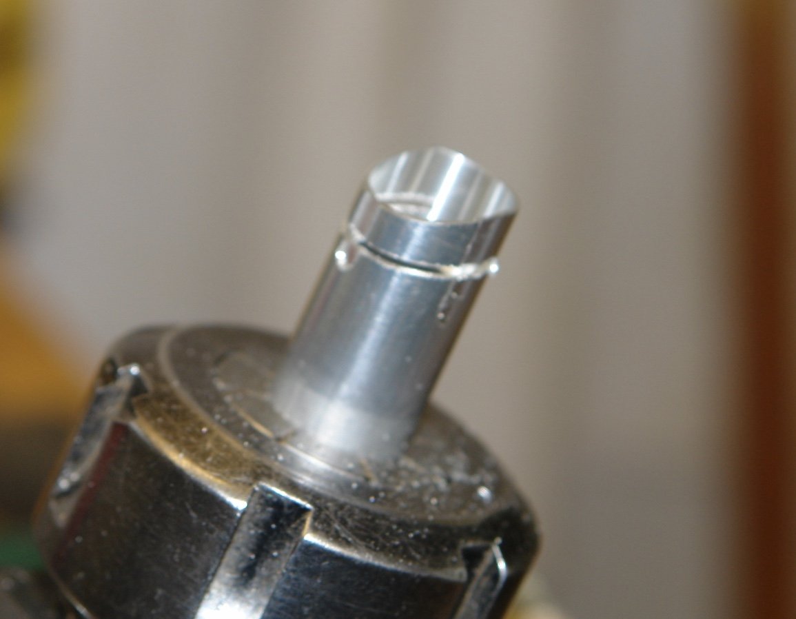
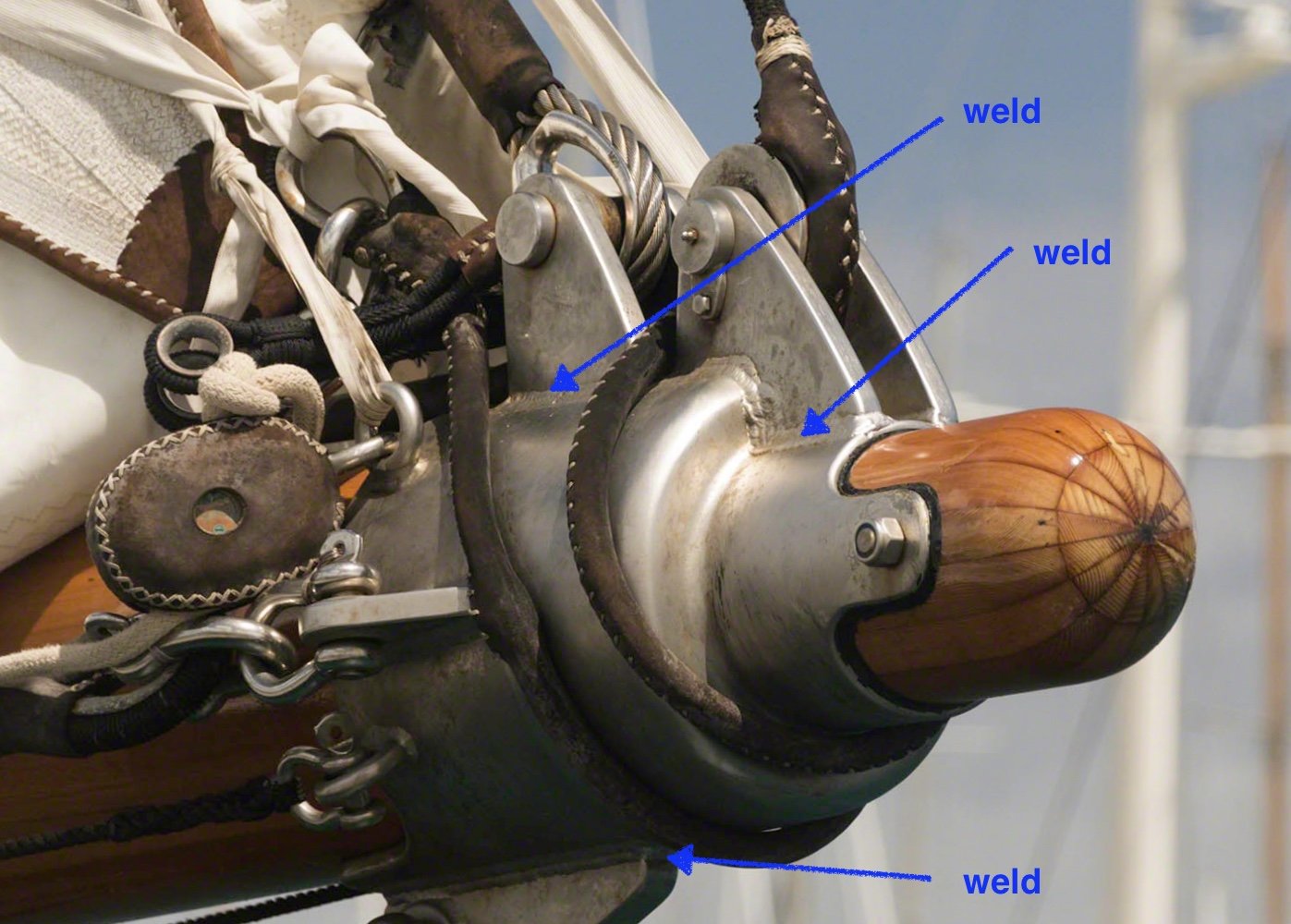
Thank you Richard. Thank you Eberhard. This photo would suggest that it is fabricated
-
You missed you vocation Geert, you should have been a seamstress. Beautifully neat sail making.
-
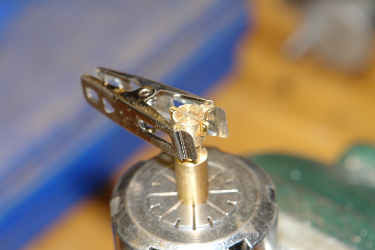
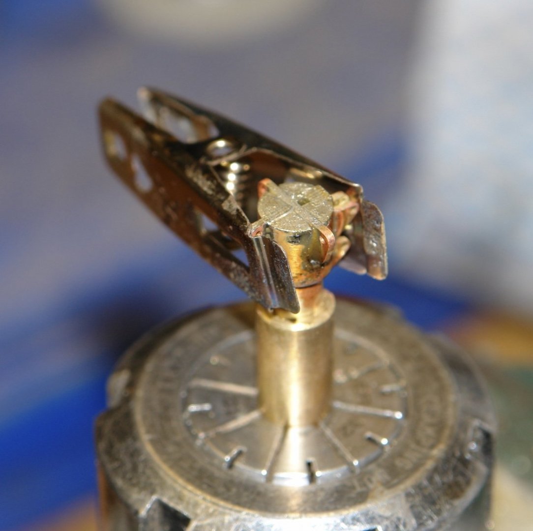
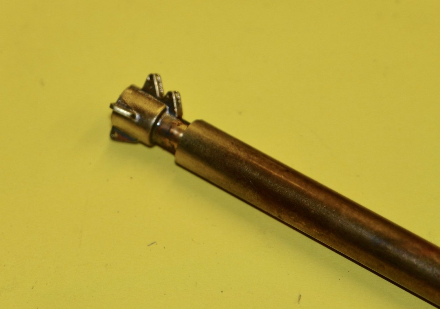
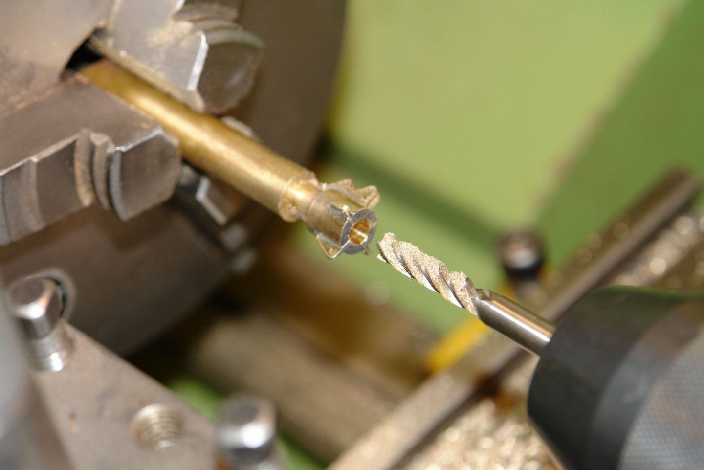
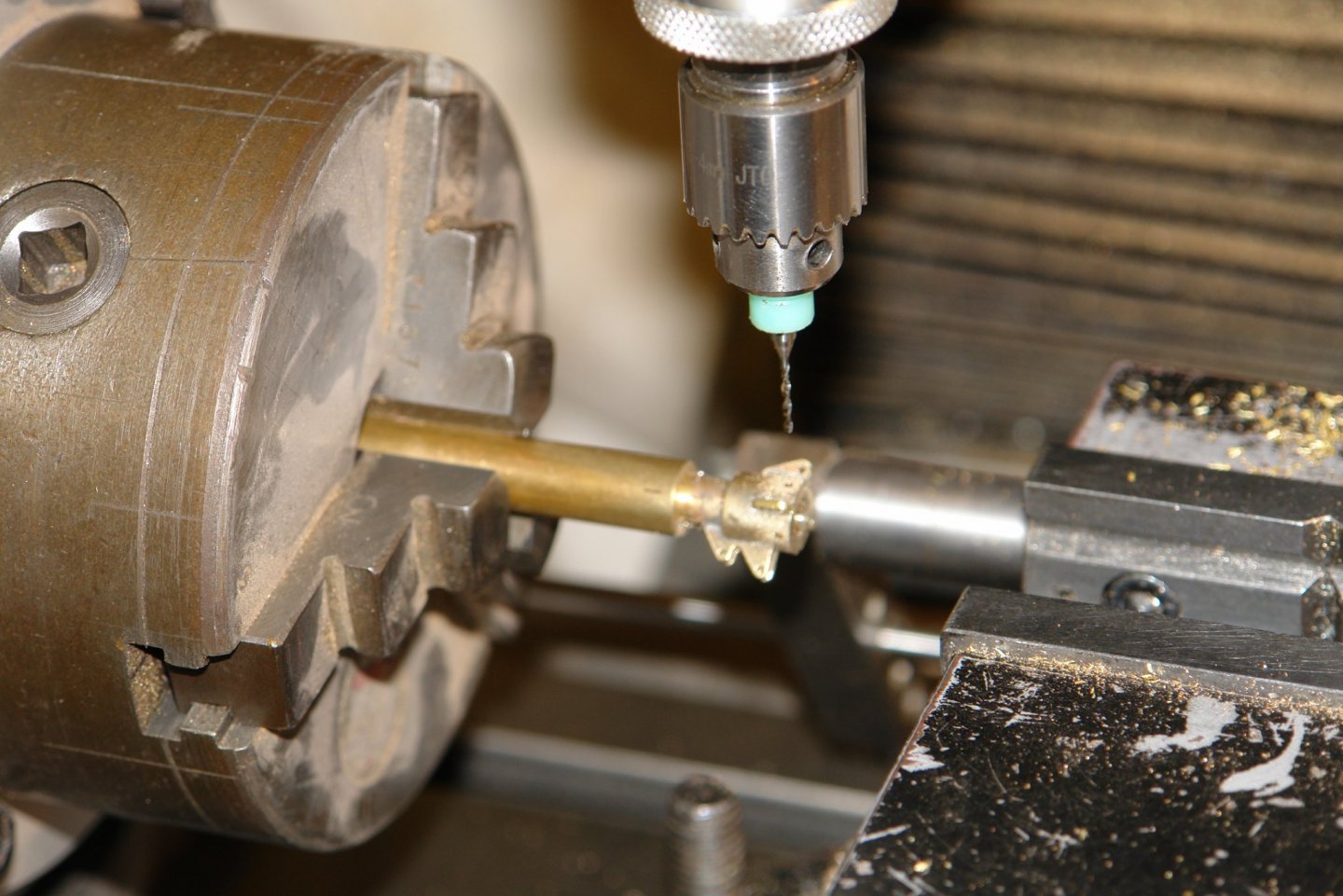
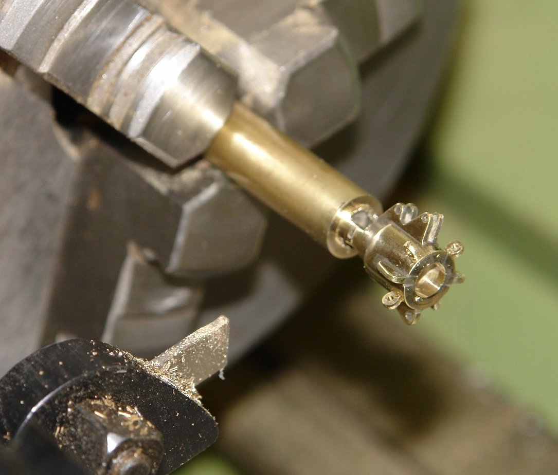
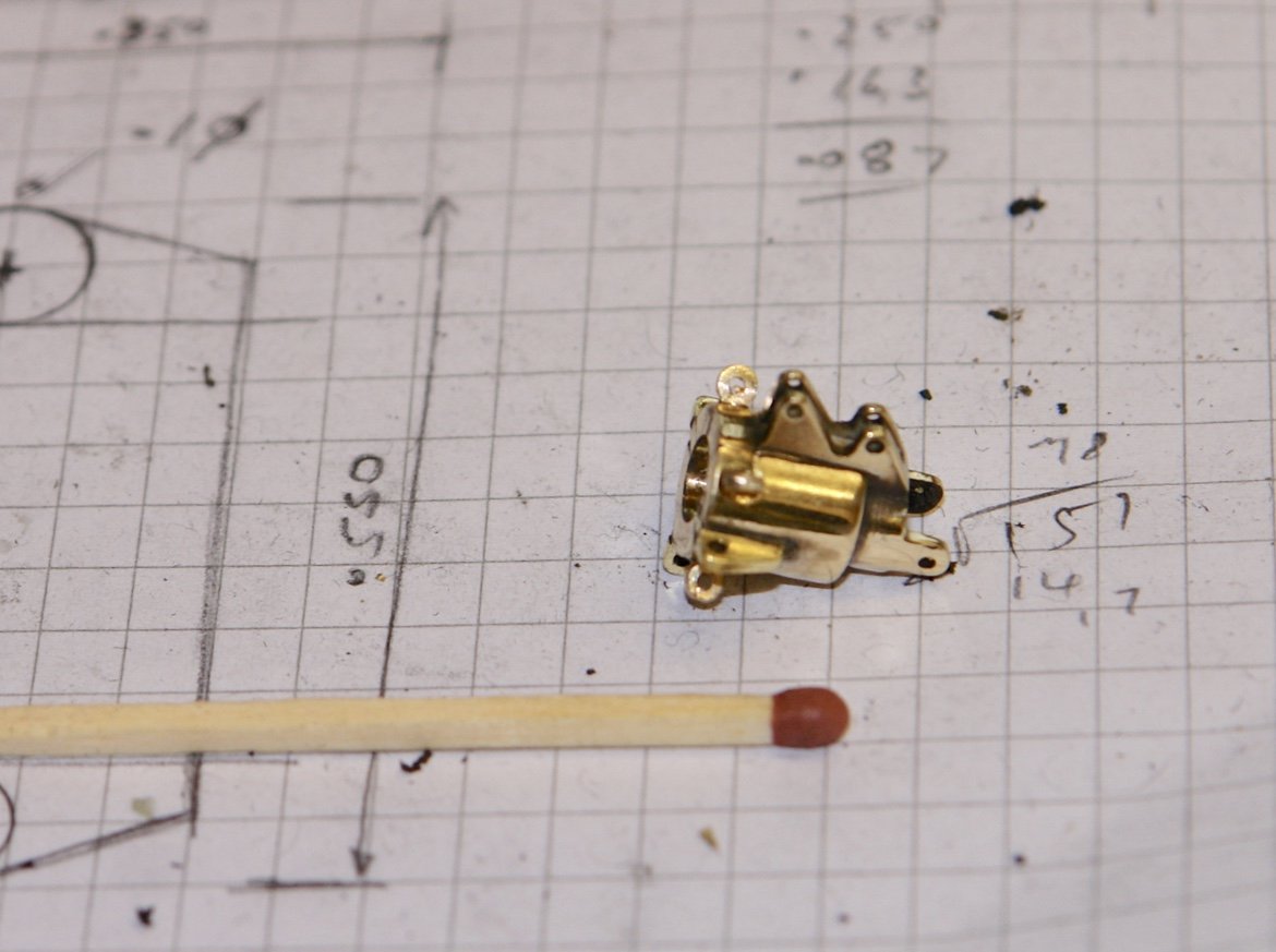
Thank you Pat. I continued with the cranse Iron as the storm developed outside. 70mph winds and 4 inches of rain over the next 24 hours. I next made the east / west flanges as one piece. Much bigger file buttons this time - 0.1" diameter. The south flange was similarly made. With all 3 components made it was time for assembly. with the hub vertical I put the east west flange in place followed by the north and south flanges. I used a steel clothes peg to stop the latter falling out, Flux and solder were then placed on the top surface and heat was applied using as blow torch. After cleaning with a wire brush I had this:- .The next step was to bore through the boss. Because of the discontinuities created by the flanges I was expecting the drill to wander off centre and it didn't disappoint me. I purposely drilled the pilot hole at 0.1" diameter and finished the bore with a 0.2" (5mm) end mill to pull the hole back into alignment. The next step was over to the mill where the .040" diameter eyebolt holes were drilled using the rotary table mounted vertically. 2 further holes were also drilled to take the fixing bolts for the cranse fixing lugs While on the mill 2 flats were milled at the front of the cranse to form the 2 axial fixing lugs. 4 more eyebolts were made. These were glued in place with CA. Then back to the lathe for parting off and finally a decent in focus photograph. It looks much better when the photography turns out right. Once parted off another file button was used to finish off the axial lugs. And that is it - job done.
-
Eberhard - yes much easier and quite accurate. For larger diameters I would generally use the mill and a rotary table but for anything less than about 0.2" diameter buttons are my preferred choice. I will thank you - but the bed will take 6 weeks to arrive.
-
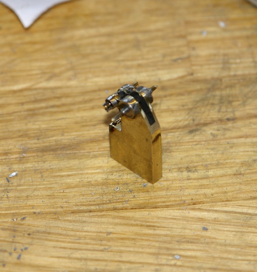
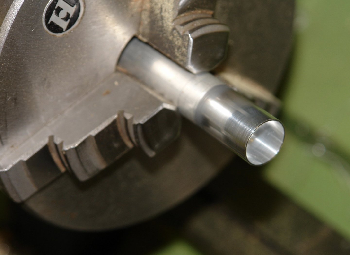
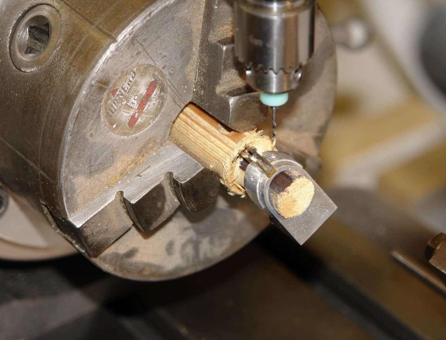
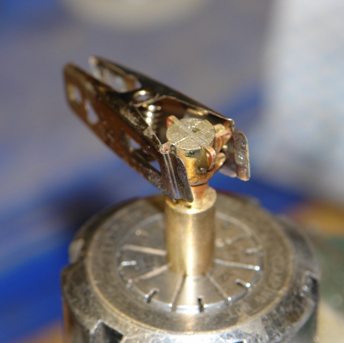
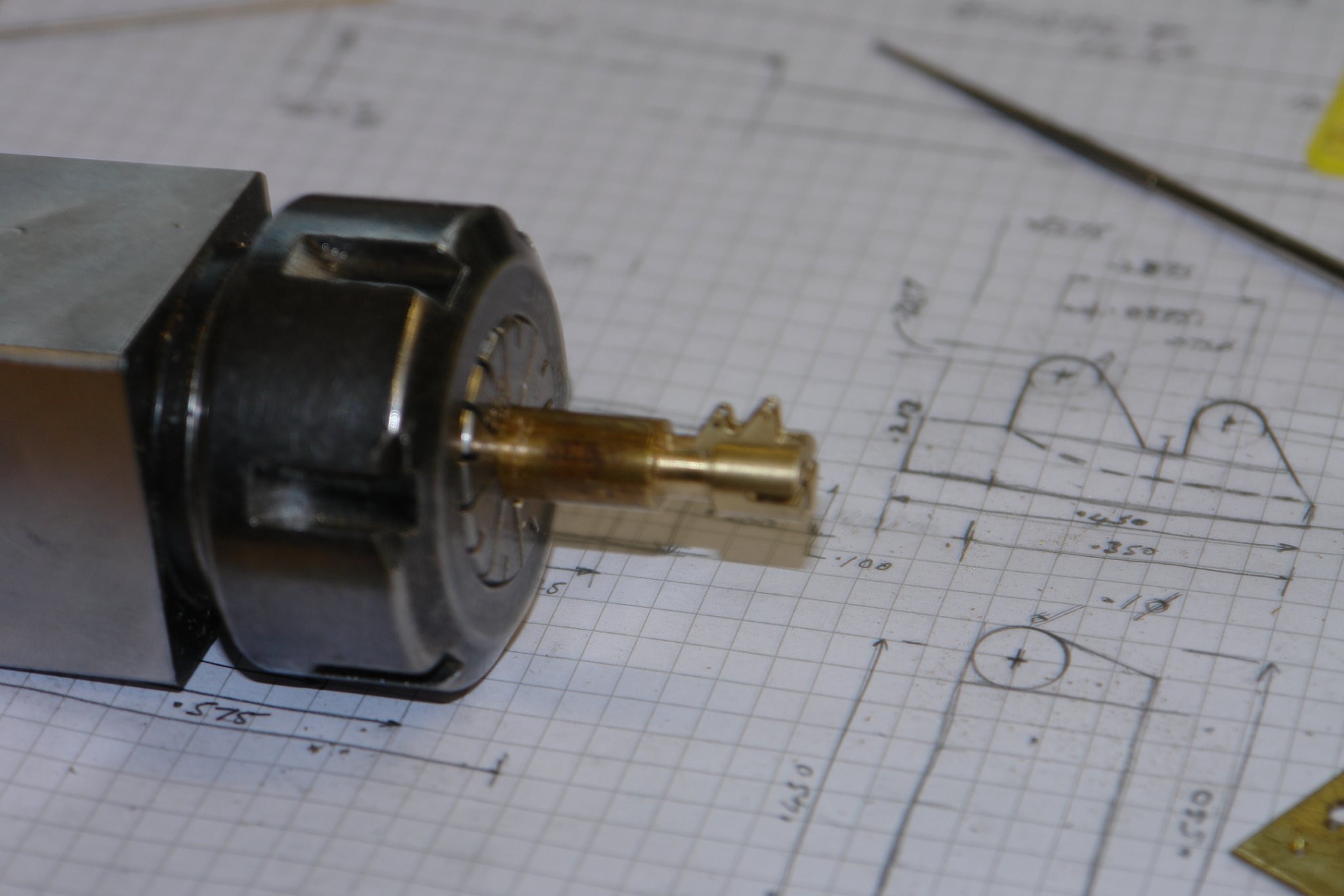
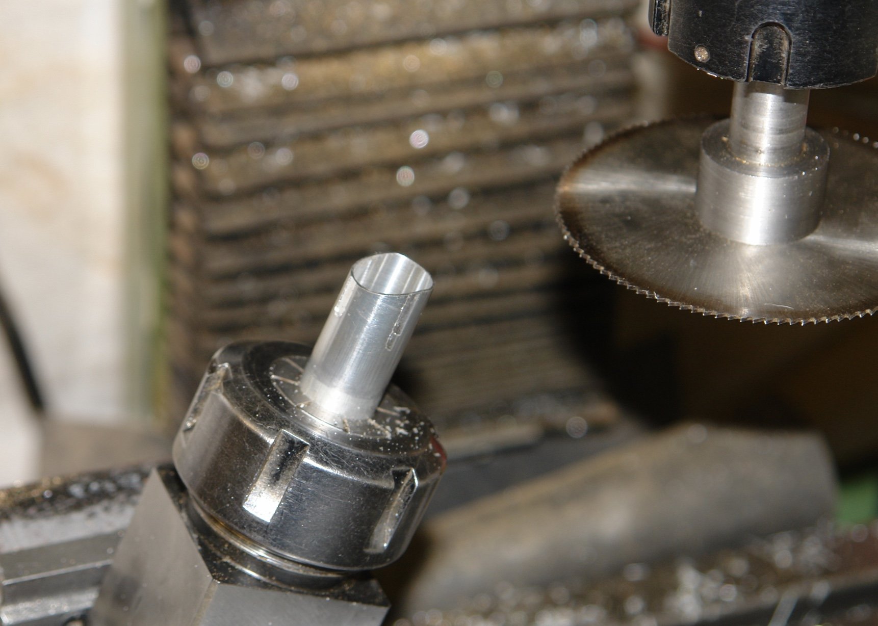
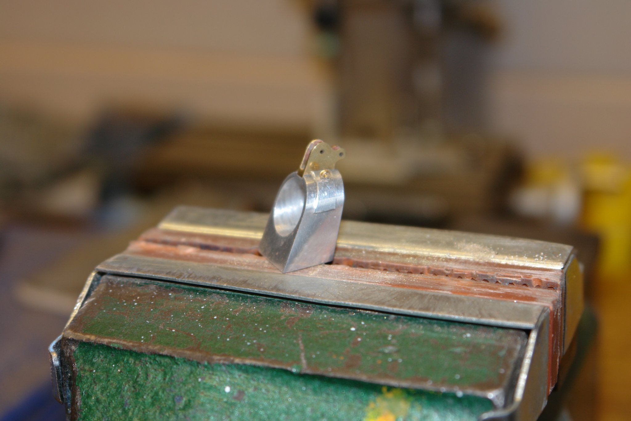
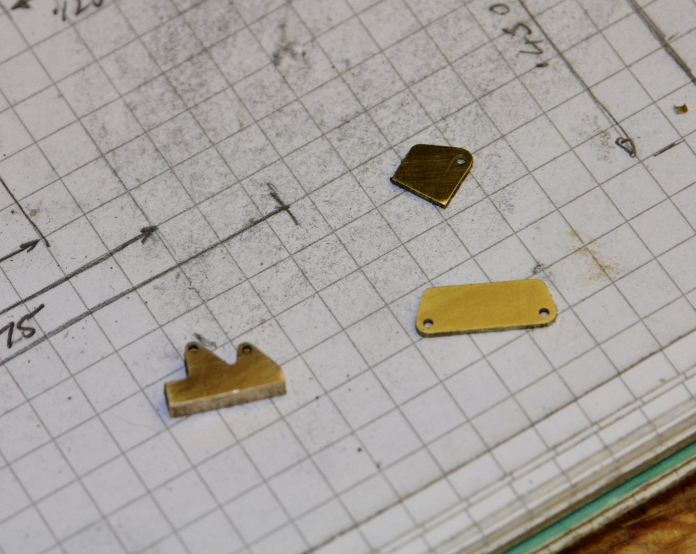
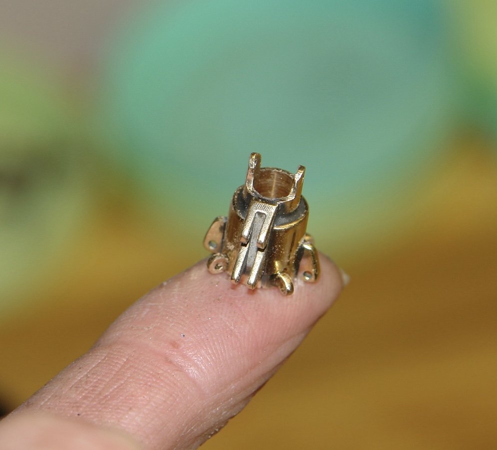
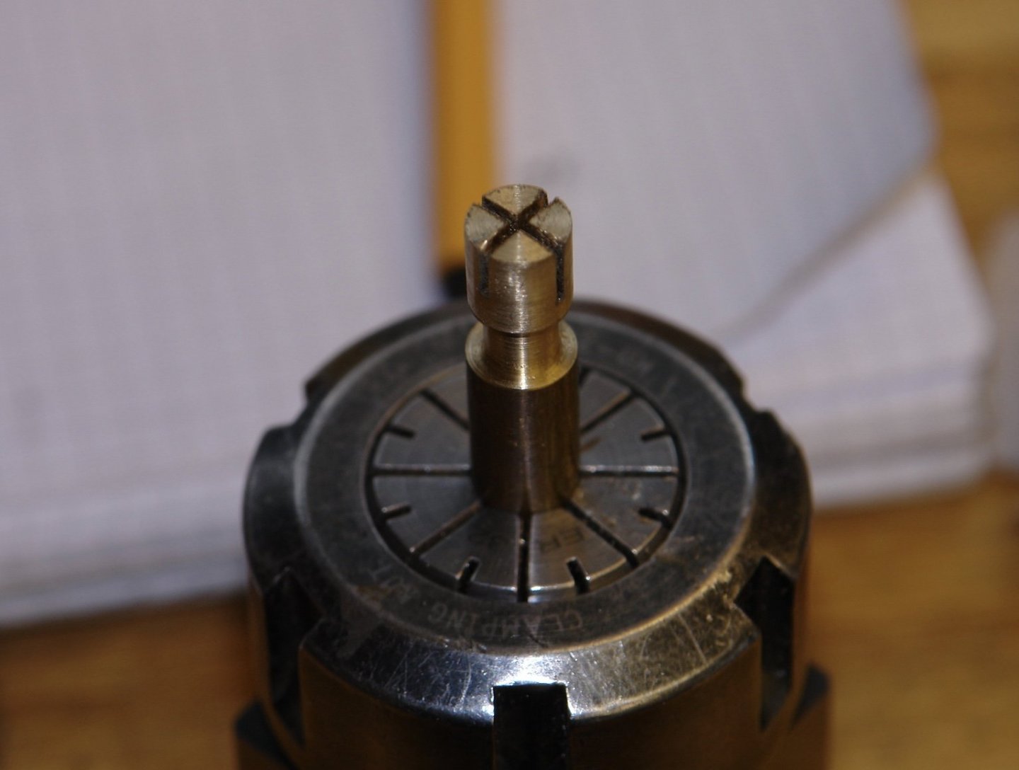
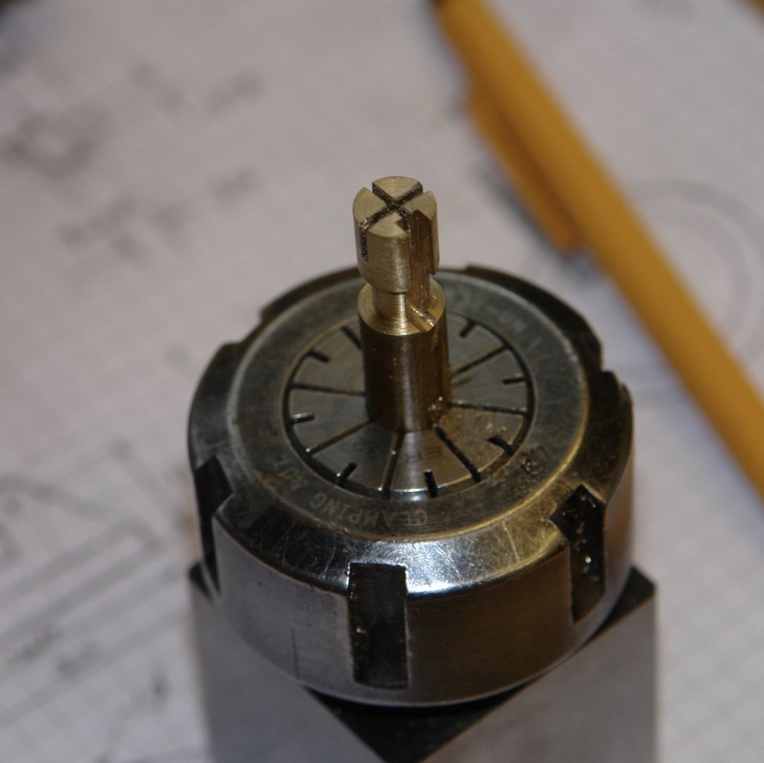
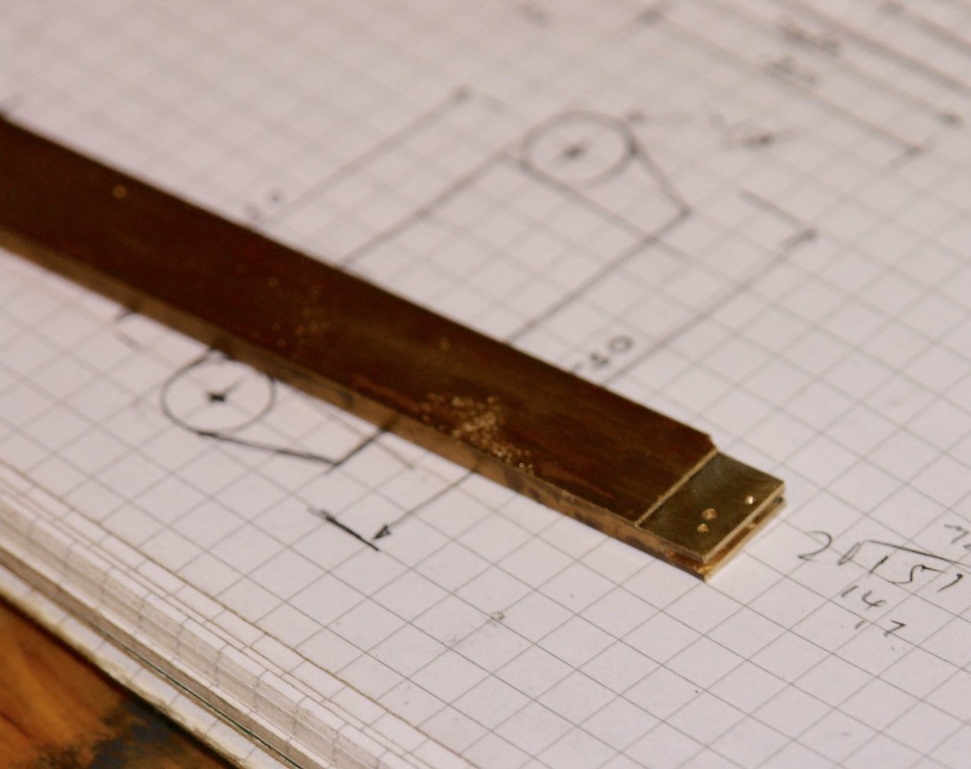
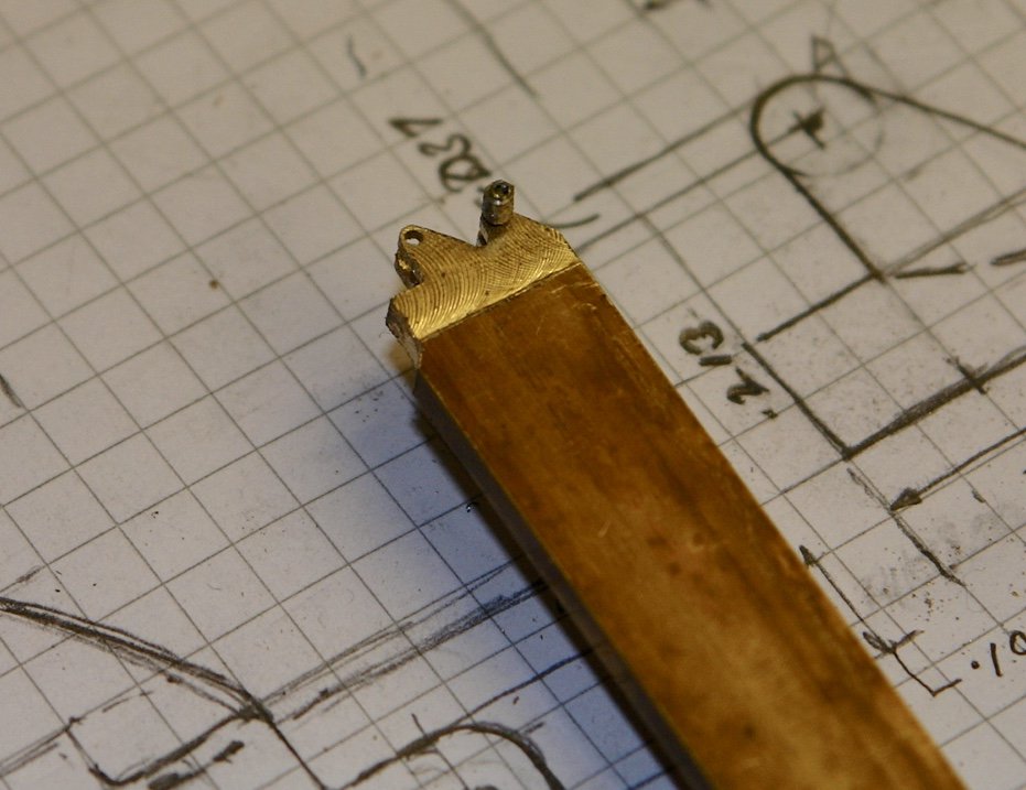
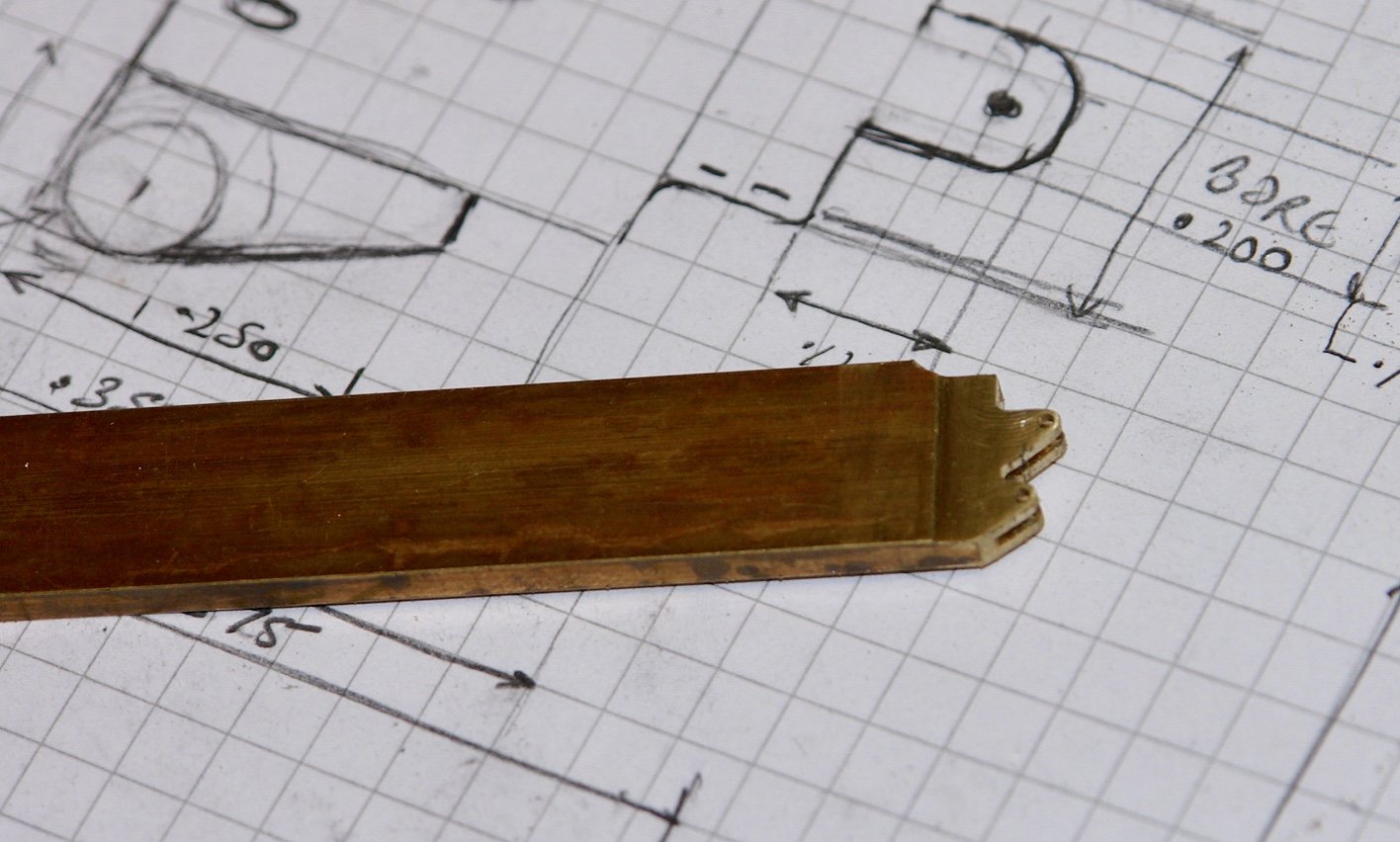
Steve - as I get older my mind get more fuddled. I started cutting metal for the cranse. Another storm is blowing through over the weekend so no distractions and I should get it finished (that is if the expected flood bypass our house). I started by turning the hub from 3/8" brass rod. I am making the cranse from brass as I will need to solder the parts together. The two diameters are .35" and .25" respectively. The large end was then slotted on the mill using a square collet block. Three of the slots will take the single flanges. On the 4ths side a .118" (3mm) slot was cut. This will take the top "u" shaped bracket. The U shaped bracket was cut from 1/2" x 1/8" brass bar milled to .118" thick. 3m holes were drilled to locate the ends of the bracket "horns" and the gap between them. A slot was then cut with the slotting saw to form the U. The horns were then cut and filed to shape using a jewellers saw and needle files. Once again I used file buttons but at .075" diameter I think I was pushing the limits of the technology. Never the less it worked. The bracket was then parted off and its fit in the hub was checked. With a bit of emery it fitted quite tightly. Unfortunately the camera autofocus does not cope well with shiny brass. At this point the boss made a rare workshop visit to remind me we were going out to buy a new bed - so that ended play for the day.

-
Steve - i am talking rubbish - of course your method will work - all I would need to do is work with the big end outward. I already started my alternative approach but will revert to yours if it doesn't work.
-
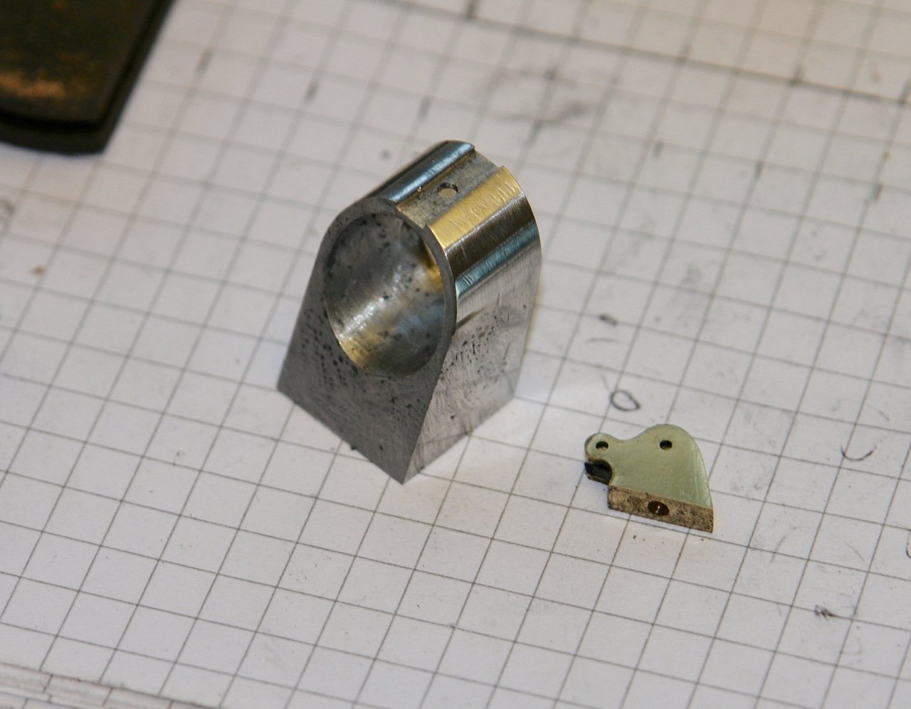
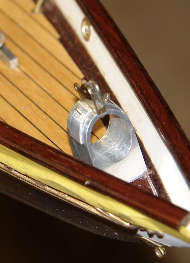
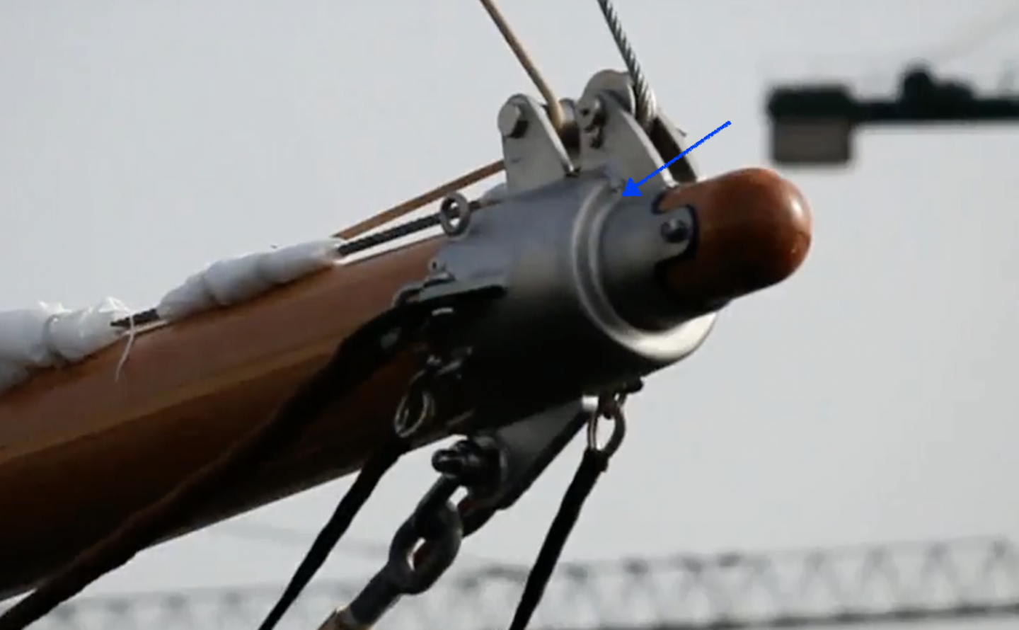
Steve / Richard - thank you for your suggestions. Steve after seeing your technique a few weeks ago i did wonder if I could use it but decided the step in diameters would make it tricky. The issue is getting into the position shown by arrow. Getting an end mill in here is a bit of a challenge and the end mill would have to be circa 1mm or so in diameter to get a reasonably tight corner. Anyway I think I have a method of fabricating it sorted out -------- famous last words!!!!!!!
-
Beautifully crisp and clean work Richard. I love the attention to detail.
-
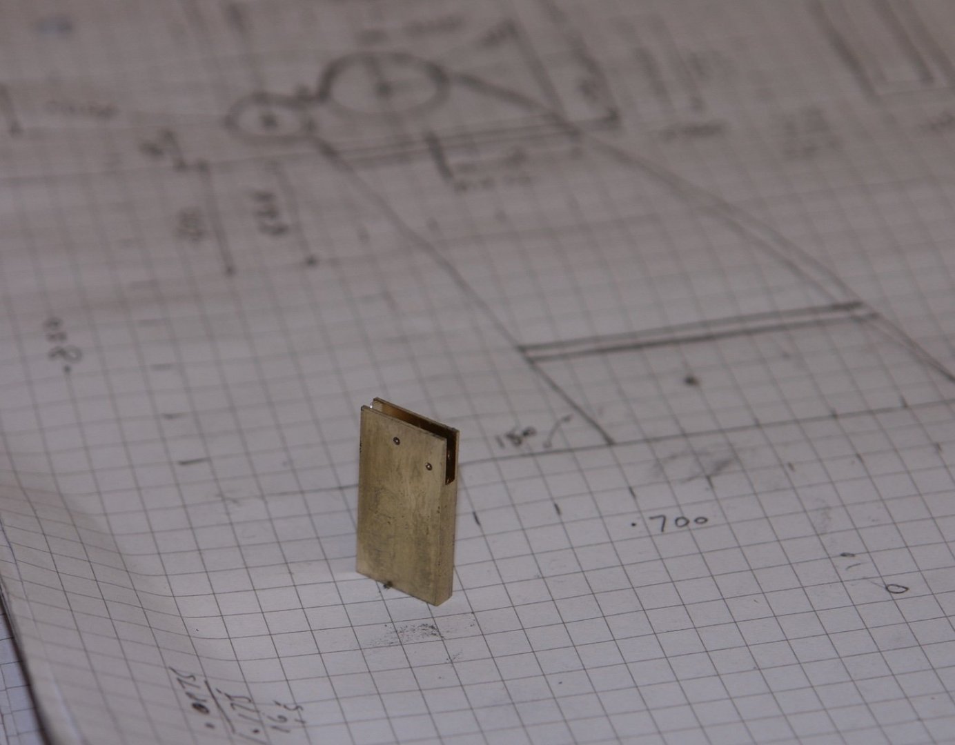
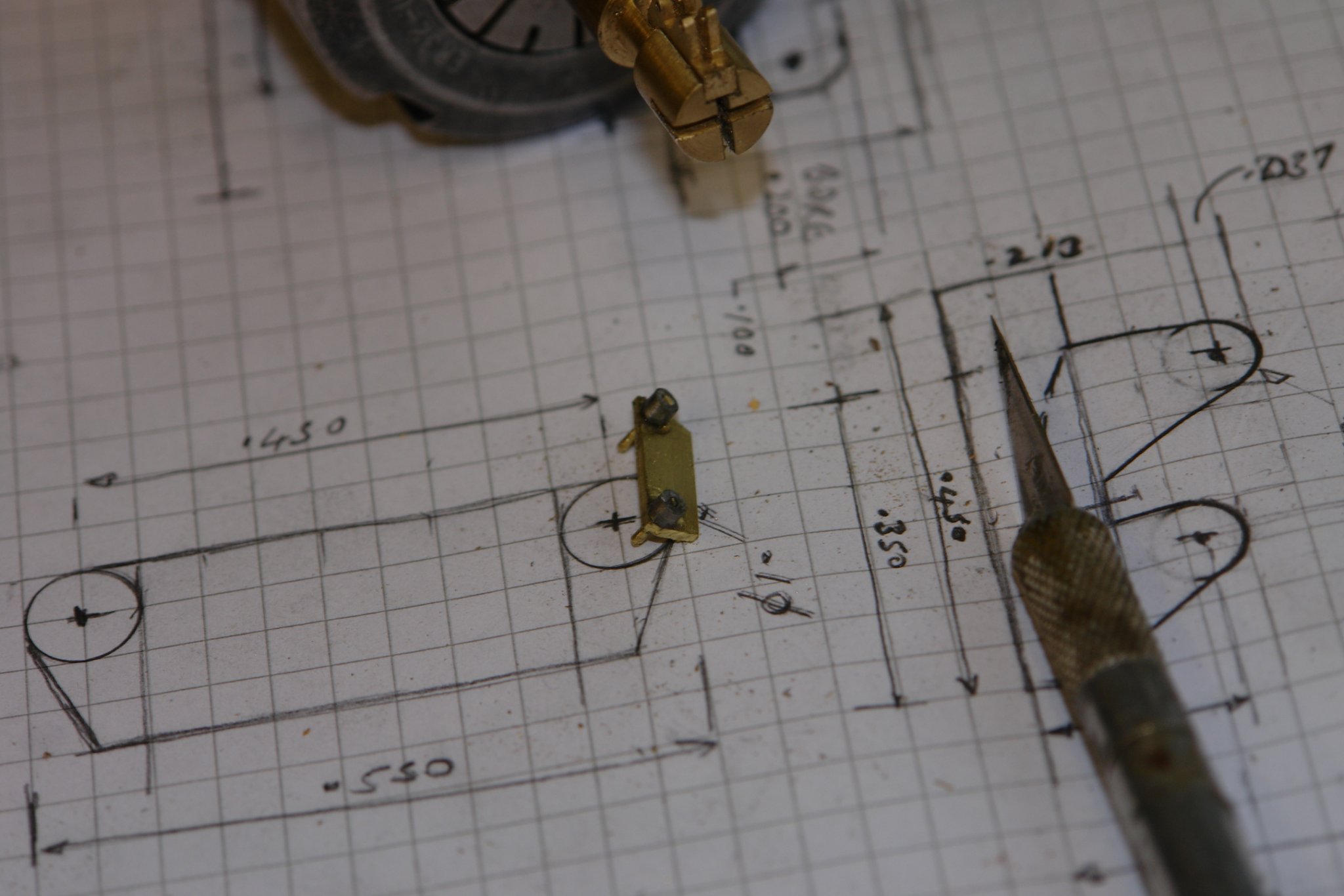
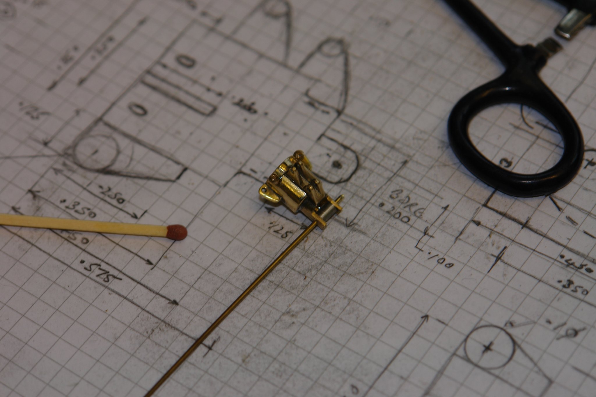
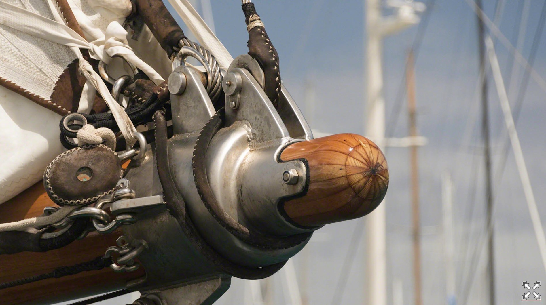
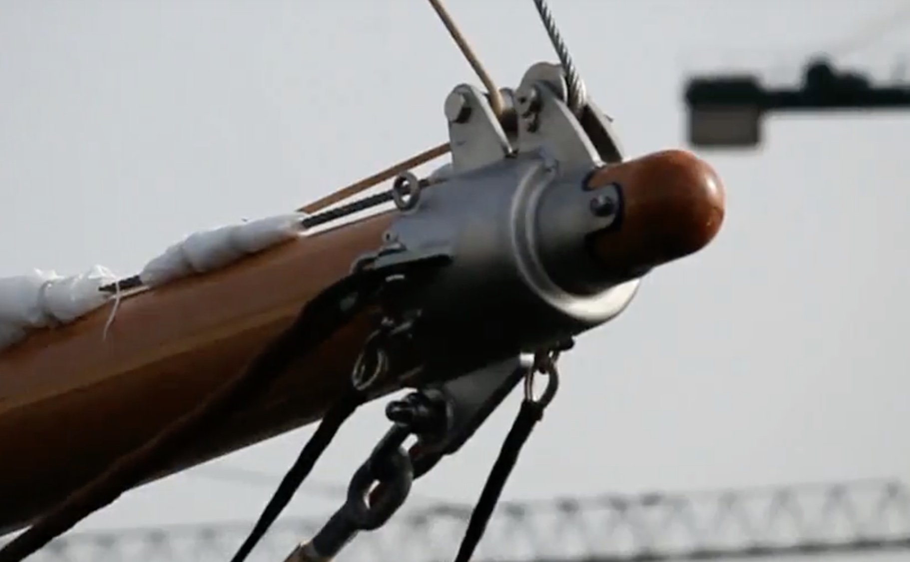
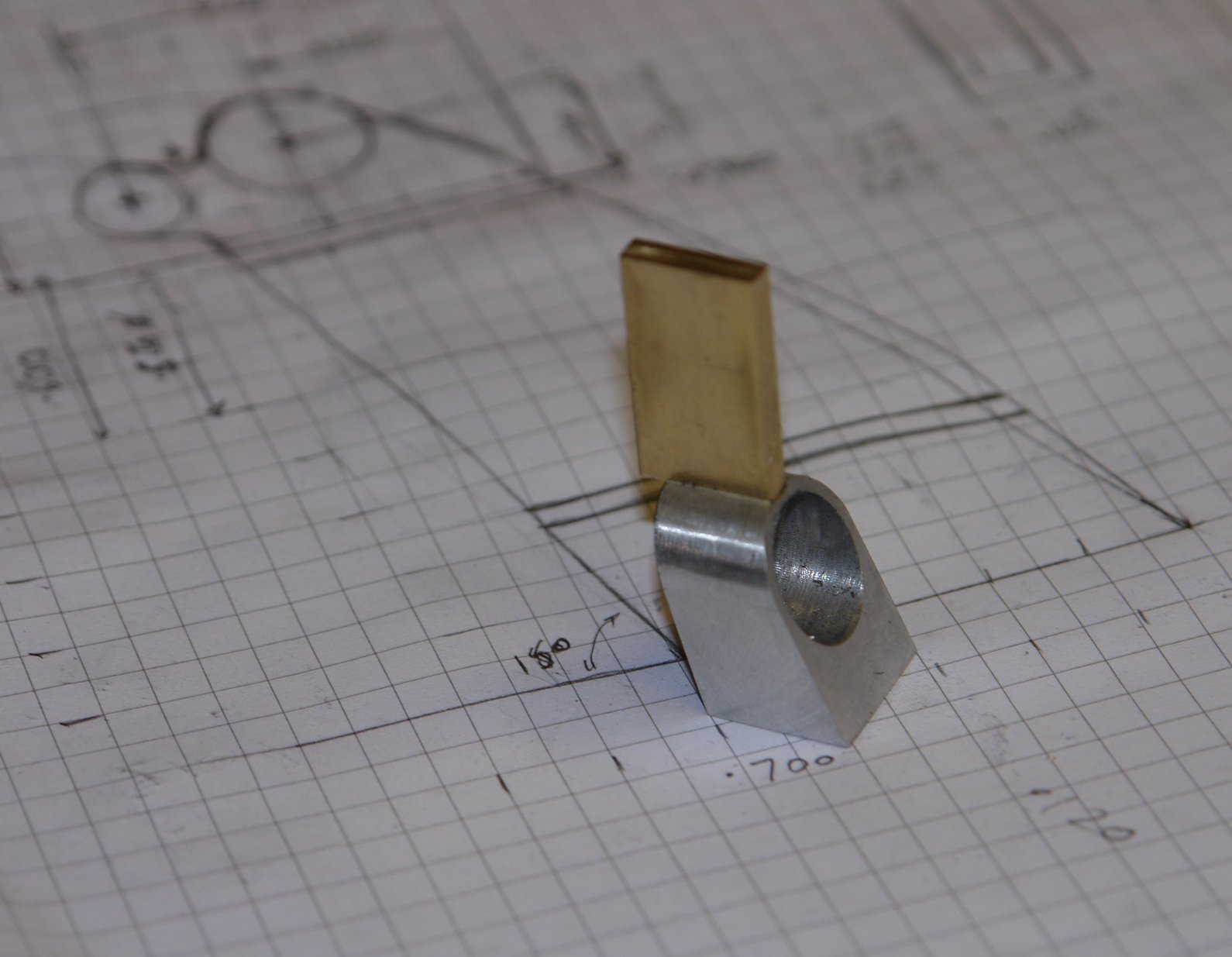
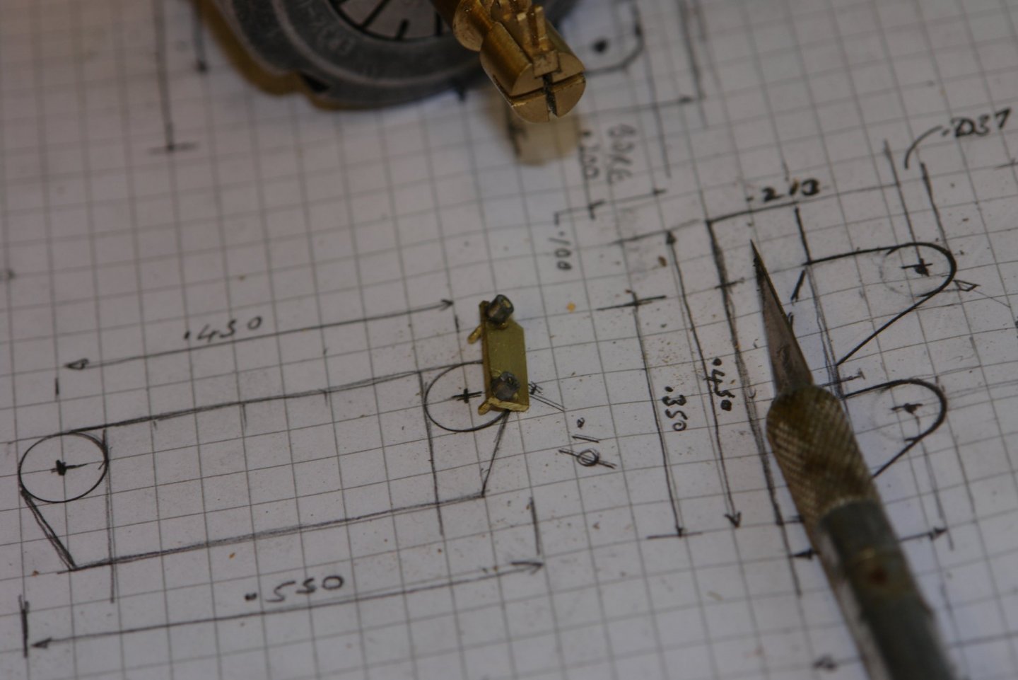
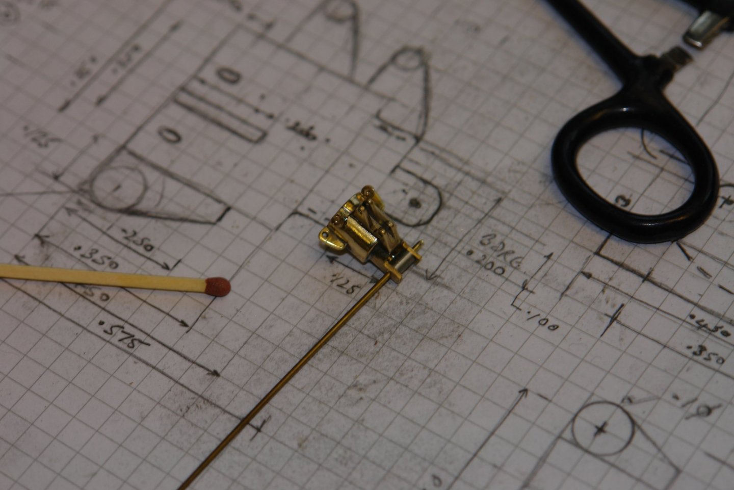
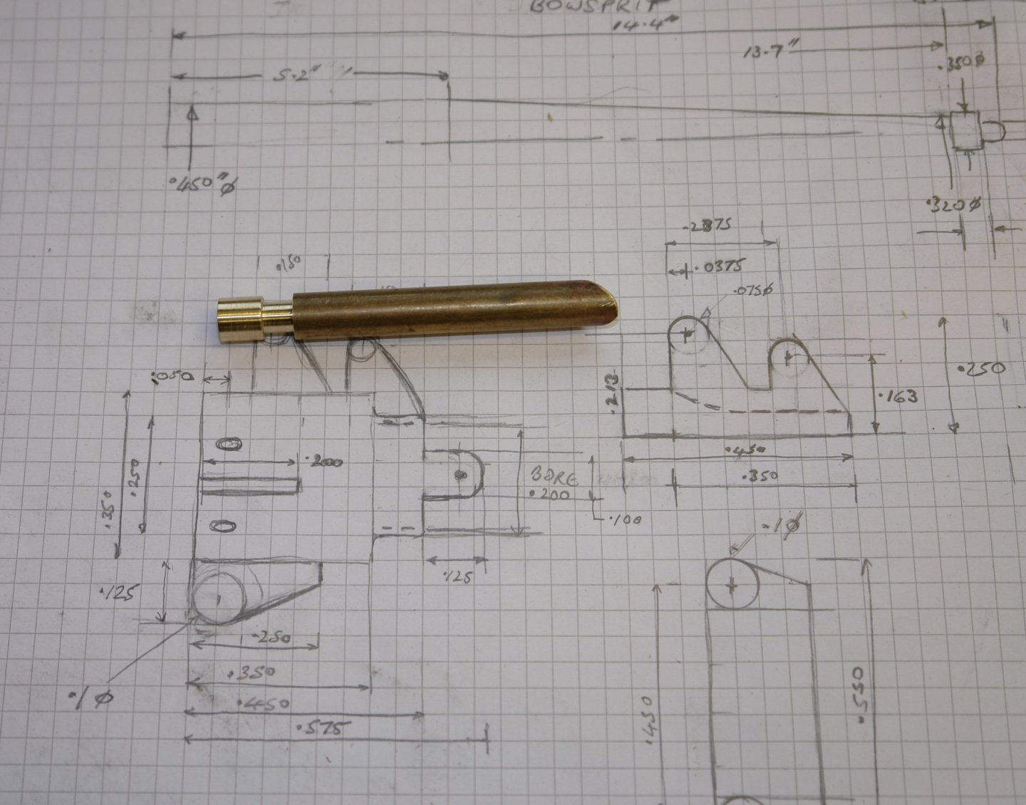
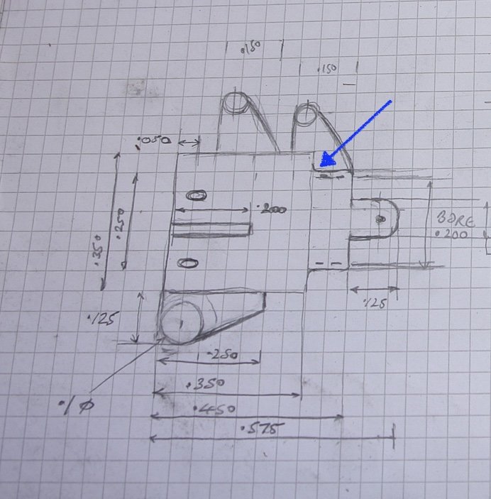
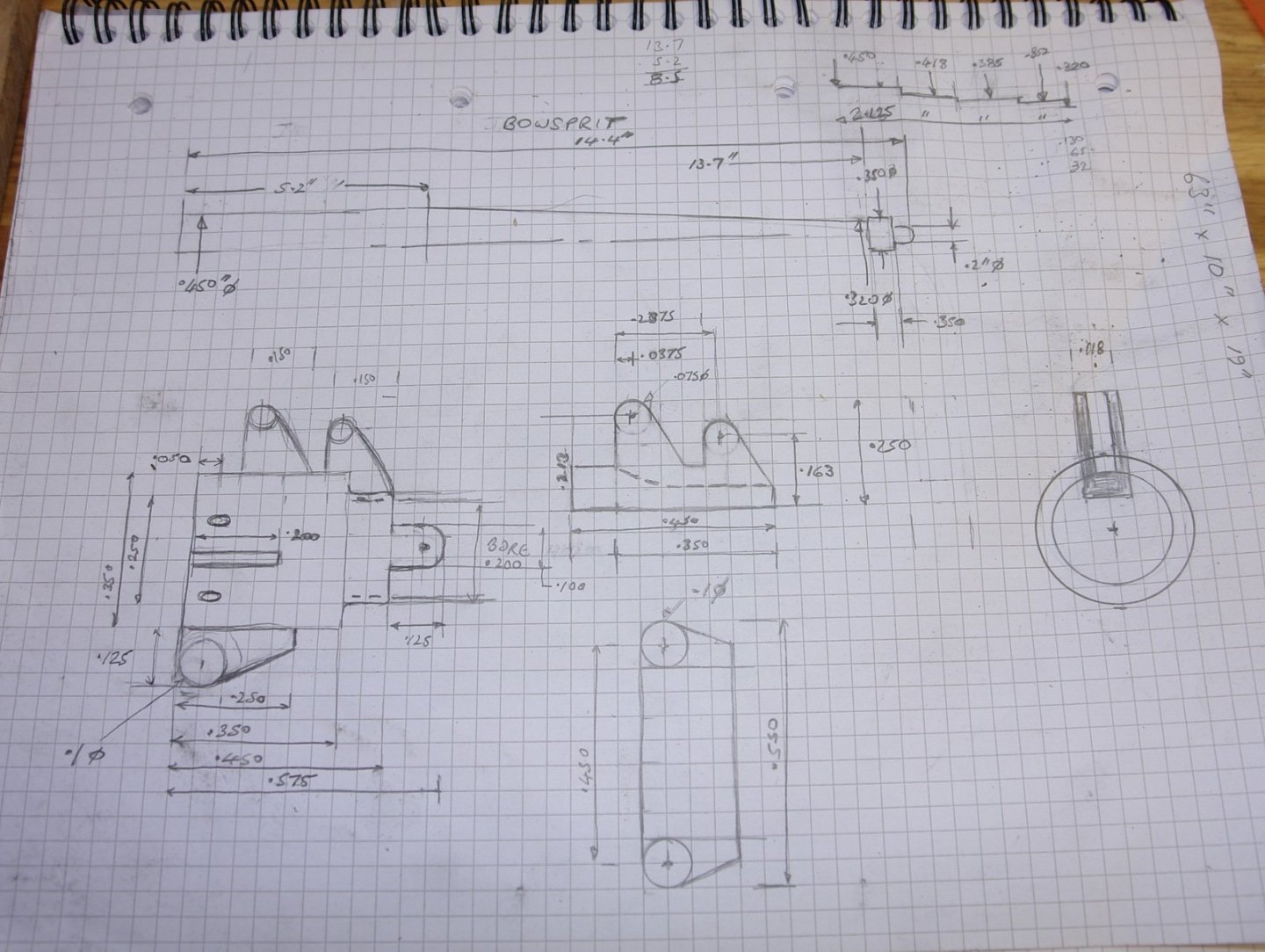
Ever since I started this build the cranse iron has been on my mind, probably because it's a bit more sophisticated than the typical ring with 4 ears. I have had a number of thoughts about how to go about it with many solutions involving uncomfortable degrees of simplification and compromise. Anyway I have decided to try and make it as realistic in appearance as I can get it. If nothing else this will give me more practice in problem solving. I will start with the photographs:- Germania's cranse iron is a bit of a nightmare of flanges and eyebolts. it has 2 "U" shaped brackets at the north position with a further 3 webs at east, south and west respectively. An additional 4 eyebolts are positioned at NE, SE, SW and NW. The rigging is a bit of a mess in the above picture but somewhat simpler in the partially rigged photo below. All this comes in a fairly small package at 1:36 scale as can be seen in the following sketch. The diameter of the hoop being .350" and the length of this section also being .350". including the smaller dimeter hoop and its associated fixing lugs the overall length is .575". I hope to start cutting metal tomorrow.


-
Eberhard - Yes they will be left brass - I quite like the contrast between the aluminium and brass. Maybe I will steer clear of gunsmith dovetail cutters. They sound too expensive to break. Pat, Michael, Richard - thank you for your kind comments.
-
That sounds like a good idea Steve - must try it.
-
Very neatly done Eberhard. I am surprised that the designers decided they needed so many ports, do you know why?
-
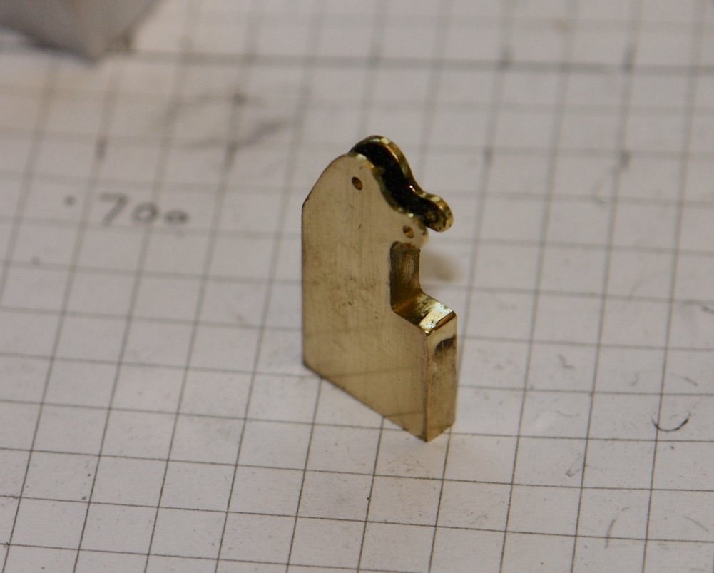
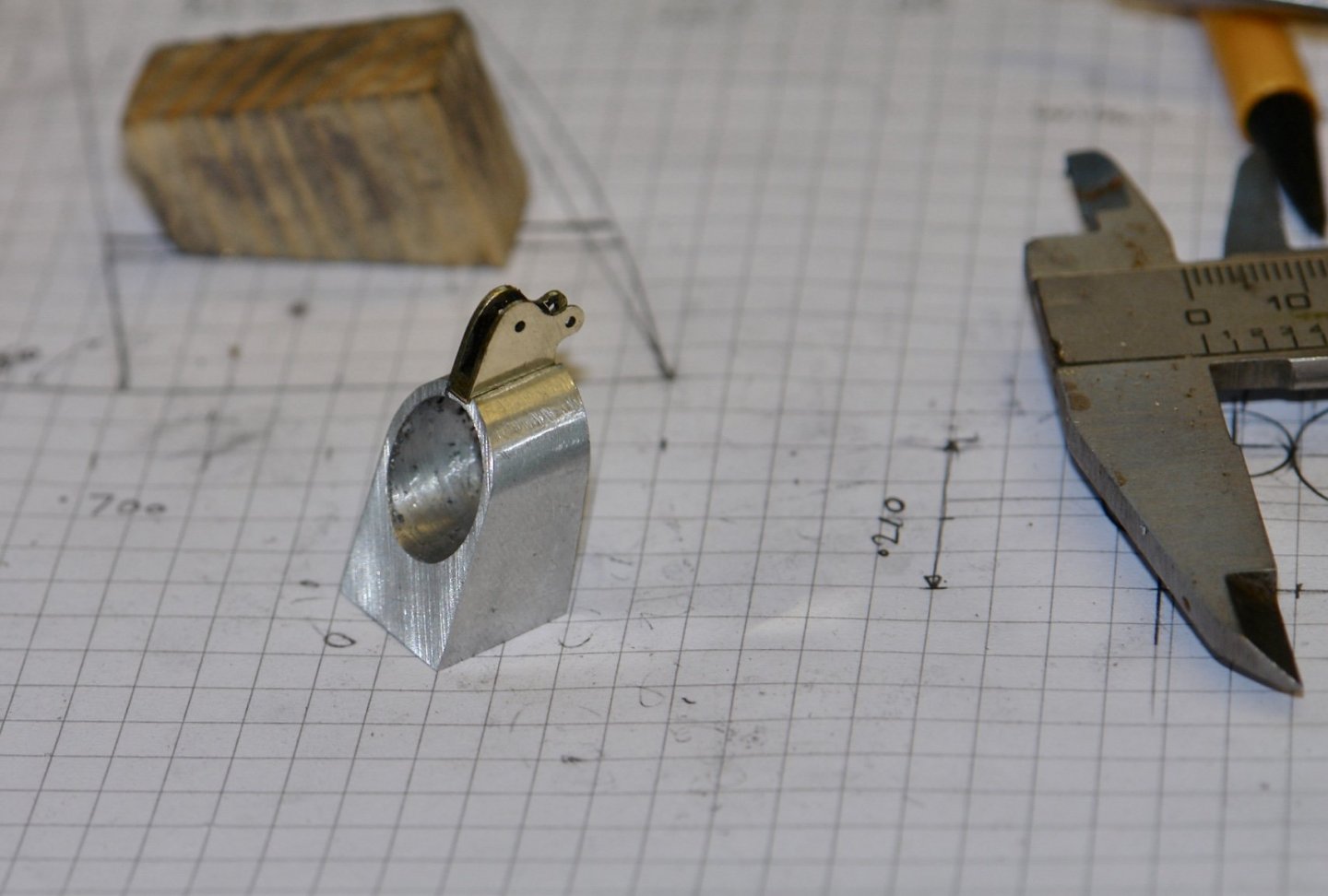
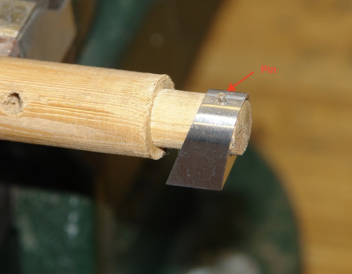
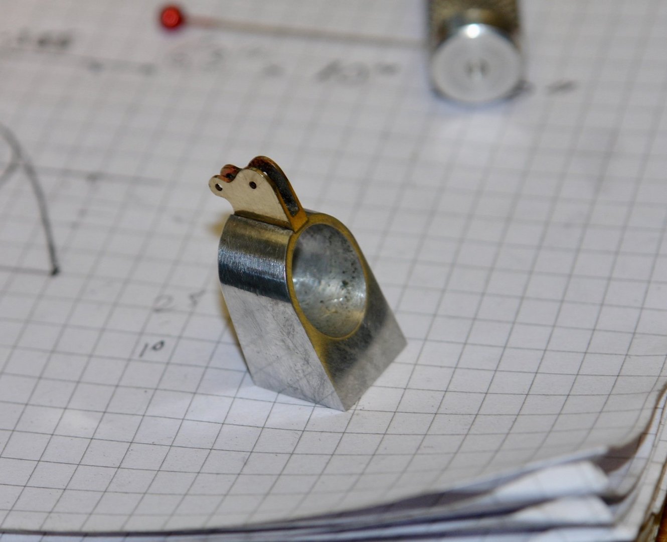
Thank you Steve / Richard. I'm glad the fires seem to be behind you Steve - it must be a relief. I spent some of the day in the workshop finishing the forestay anchor and watching the storm through the window. The top bracket was made from 1/2" x 1/8" bar. I stared by accurately drilling .040" holes at the centres of the 2 key diameters and then slitting the slot to create the "U" of the bracket I then made 2 sets of file buttons of .125" and .100" diameter respectively and filed the bracket to shape. I then drilled matching 1/16" holes in the bracket and the boss. I turned up a pin with a head of .070" diameter by .010" wide and a .062" shank. This was inserted from the bore of the boss and held in place by a scrap piece of dowel. The bracket was then placed over the 2 parts were soldered. I then needed to reproduce the thickened central section of the boss. As the bottom part of the boss is hidden I only needed to reproduce this feature on the top half of the hoop. I turned a piece of aluminium tube such that the bore matched the external radius of the boss. The wall thickness matched the up-stand of the thickened section i.e. .025". The tube was then mounted in the square collet block and the tapered profiles cut. These were then glued on to the boss with CA glue and .040" holes were drilled for small eyebolts. Eyebolts were made as previously covered and they were then attached.