HOLIDAY DONATION DRIVE - SUPPORT MSW - DO YOUR PART TO KEEP THIS GREAT FORUM GOING! (Only 44 donations so far out of 49,000 members - C'mon guys!)
×


KeithAug
-
Posts
3,957 -
Joined
-
Last visited
Content Type
Profiles
Forums
Gallery
Events
Everything posted by KeithAug
-
 Yes Richard - a 3 inch hinge would be .083" at scale size. I will put a piece of wire in place to simulate the spine of the hinge - but that will be it. Druxey - Good idea - I will try it - thank you.
 -
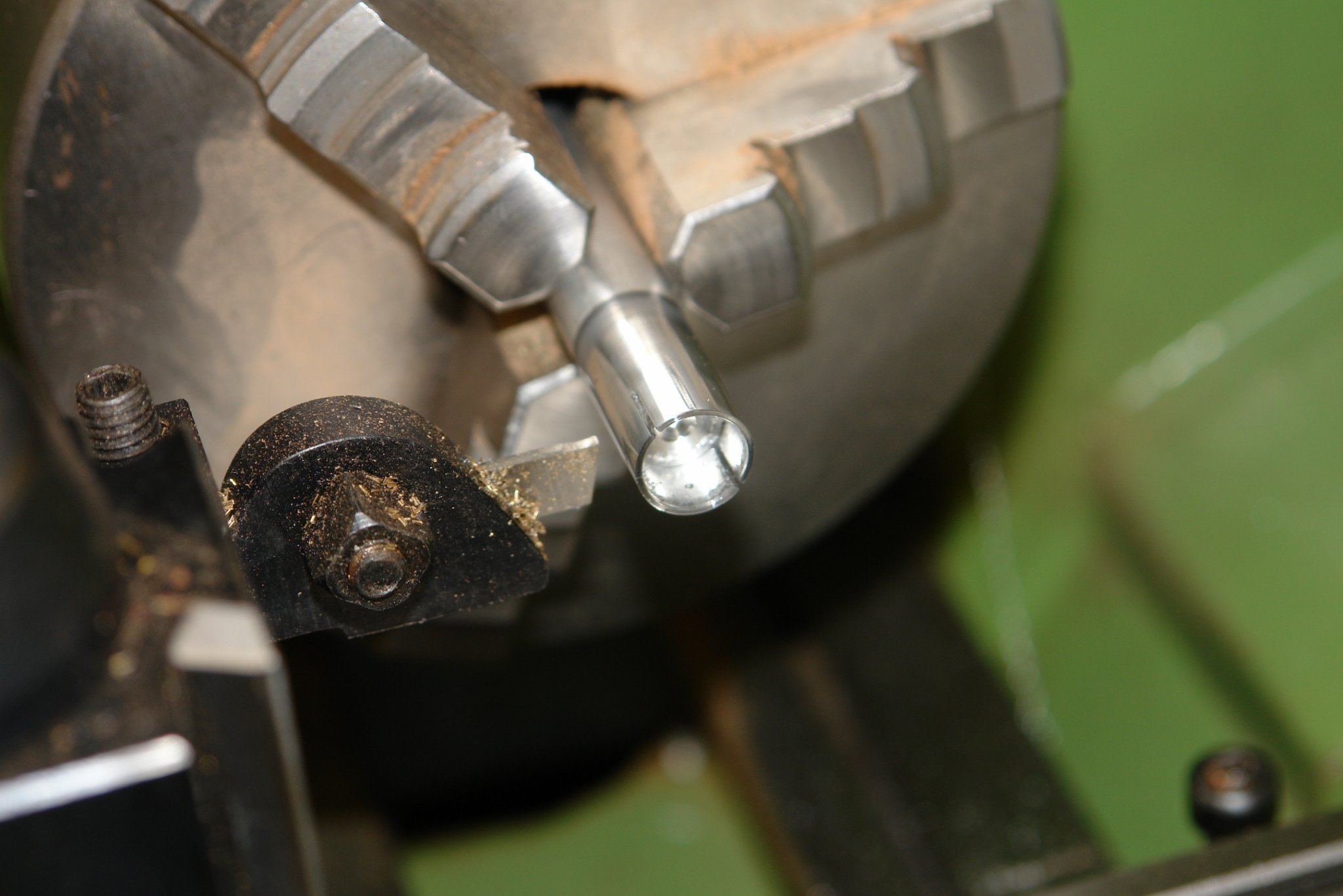
Eberhard - or alternatively make a scraper of the required radius. The turning method is quite wasteful as the side of the cutter has to be on the centreline and hence because of the kerf only one of the quadrants is usable.
-
She turned out very nicely Kevin.
-
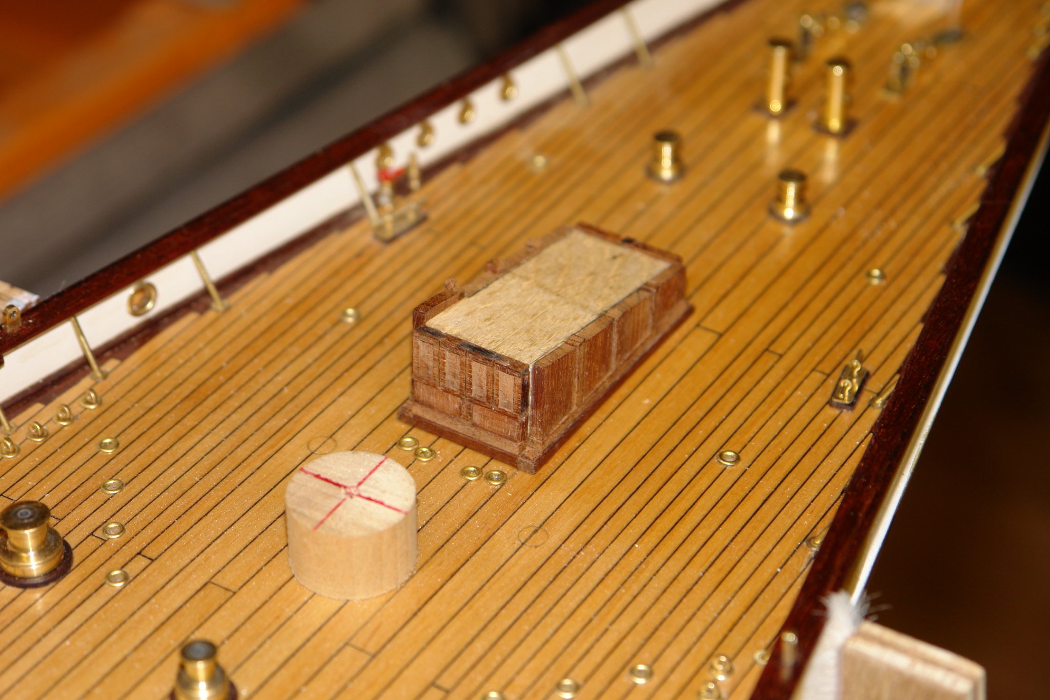
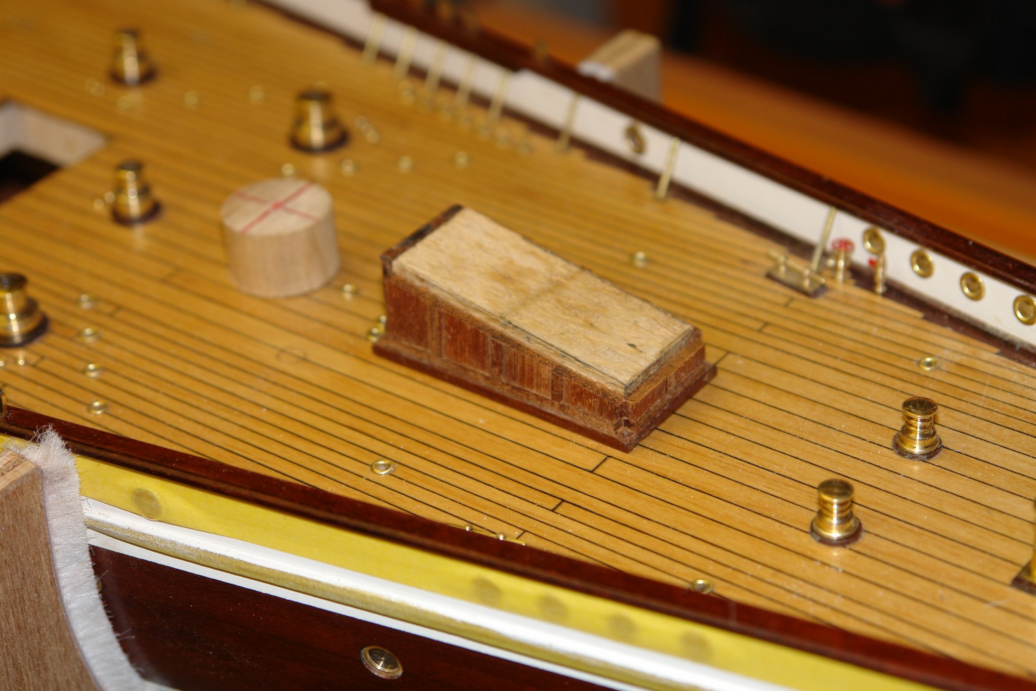
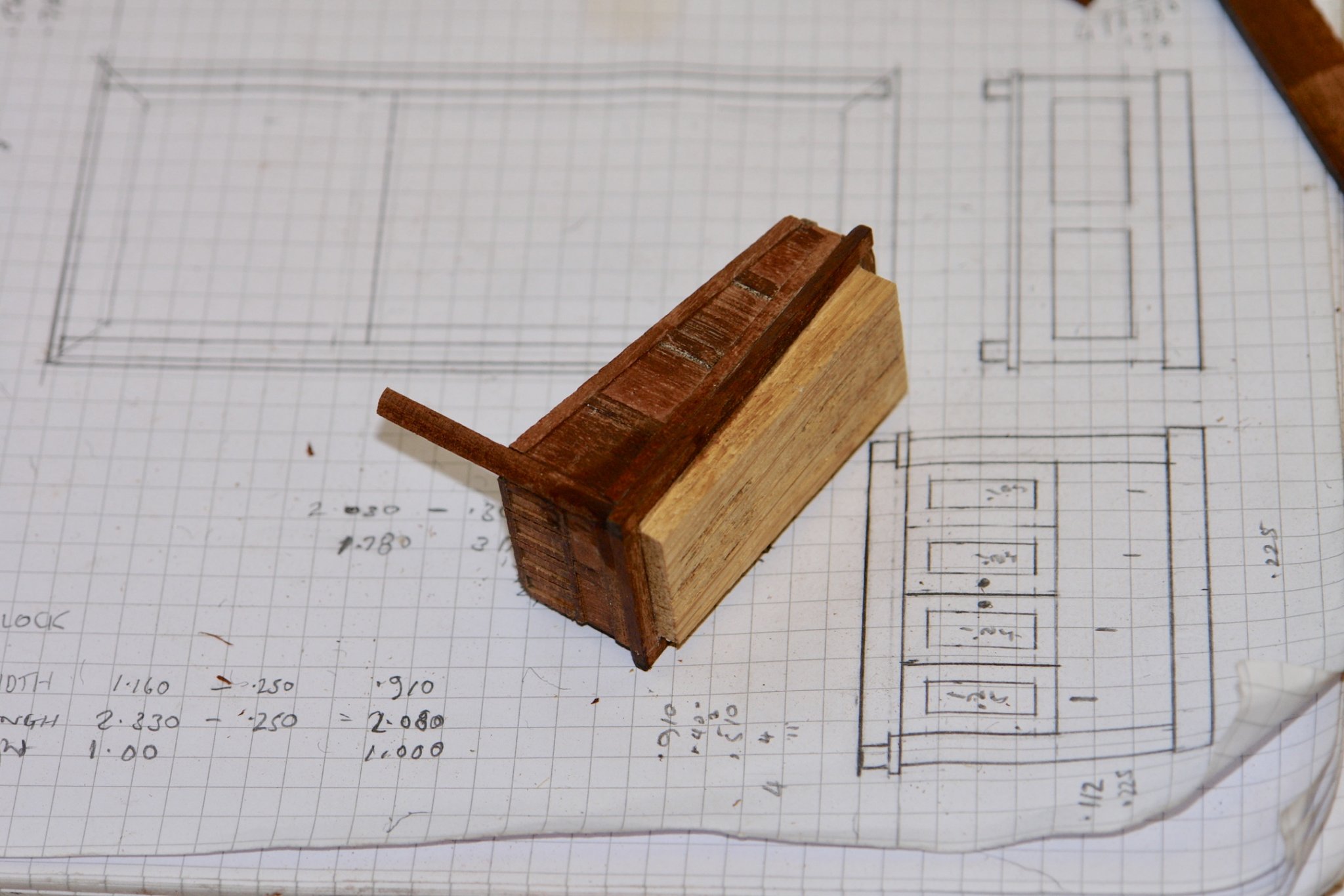
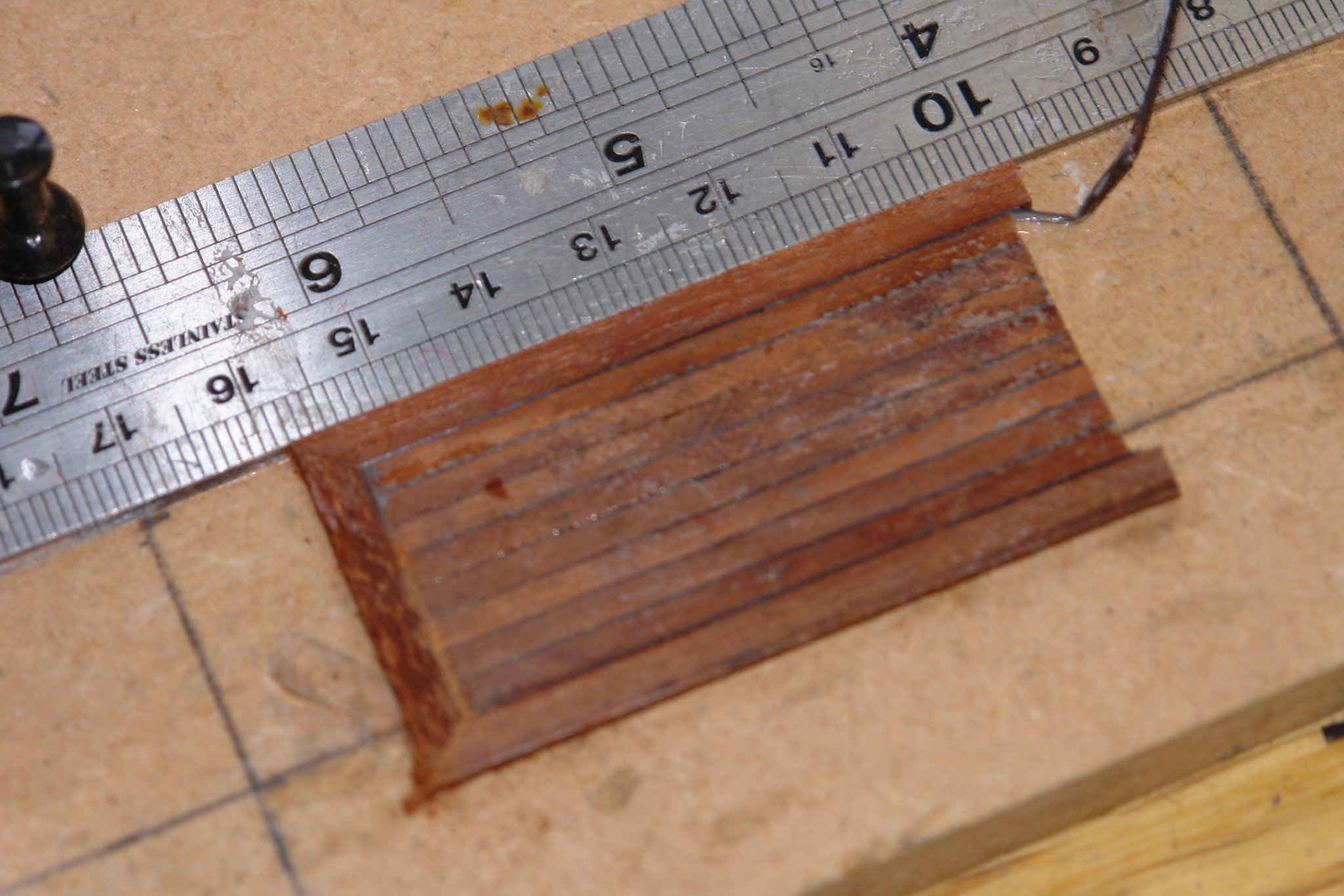
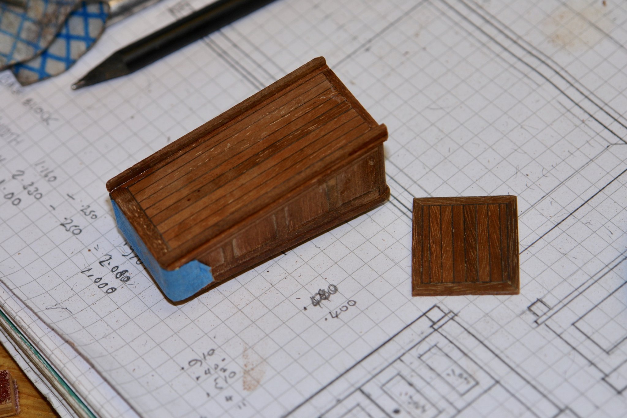
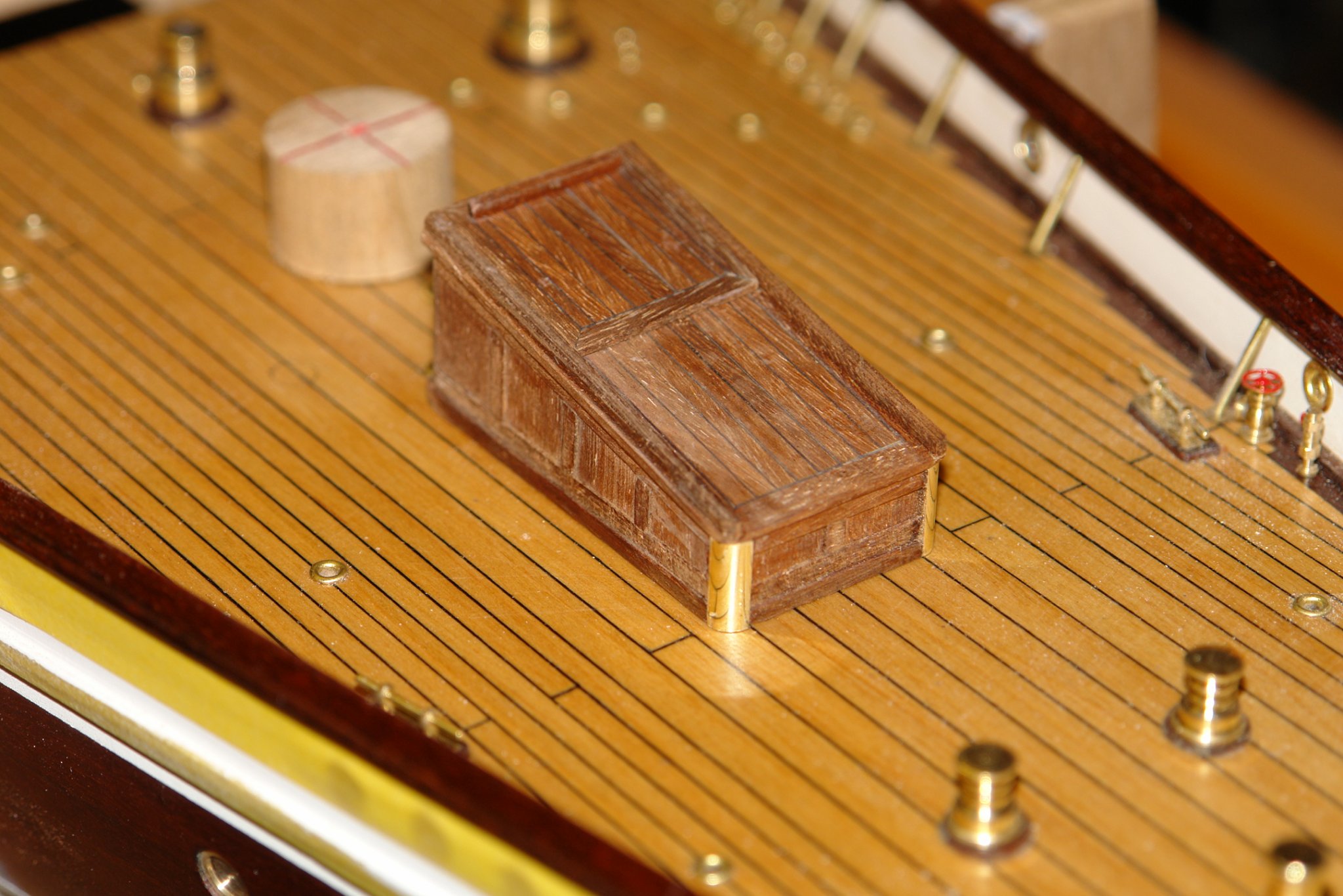
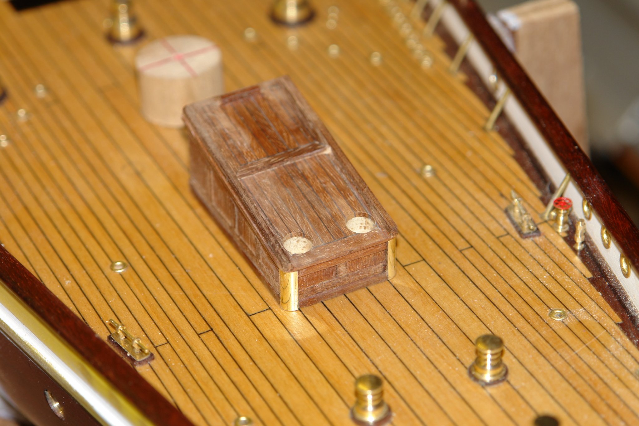
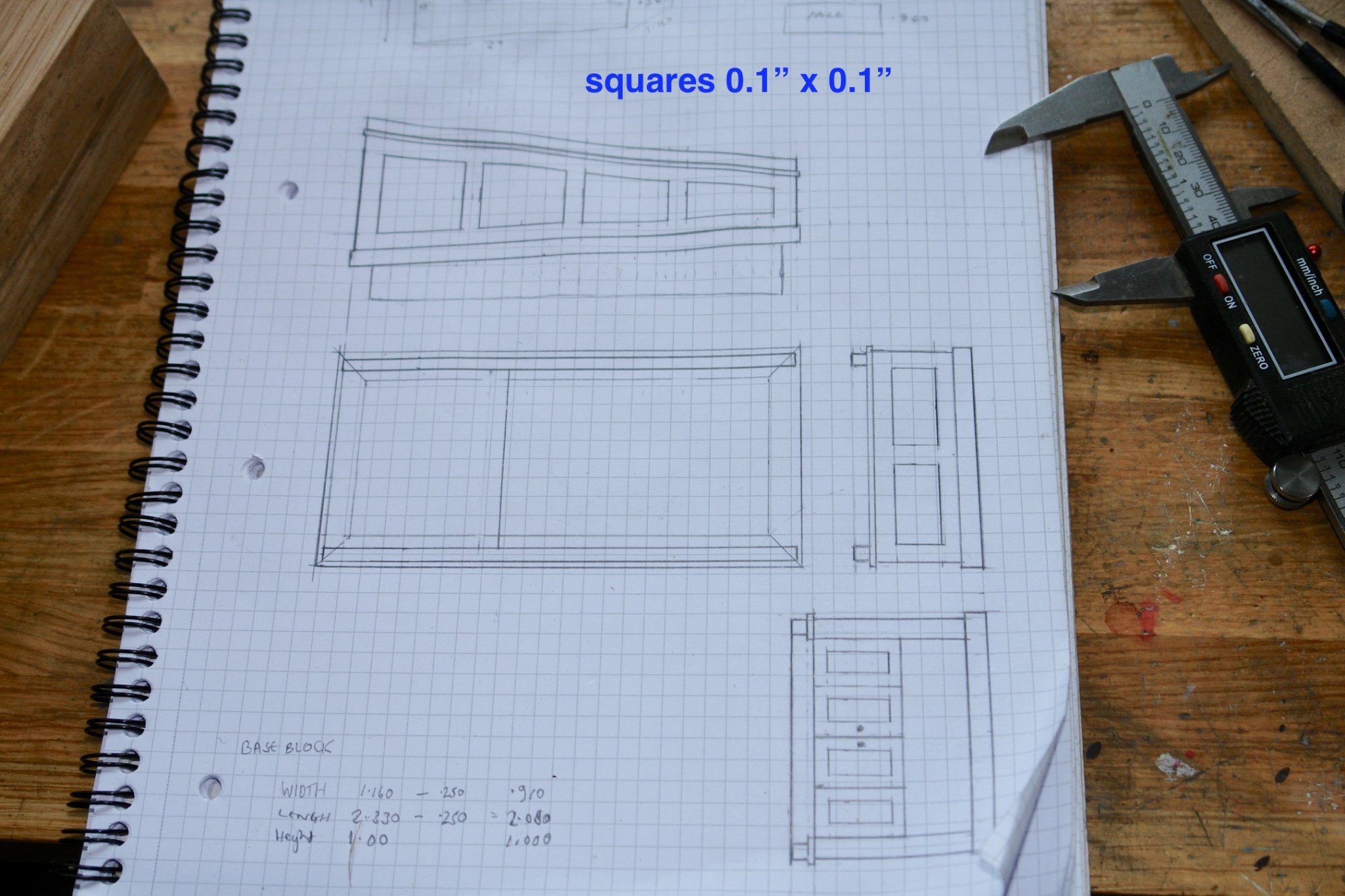
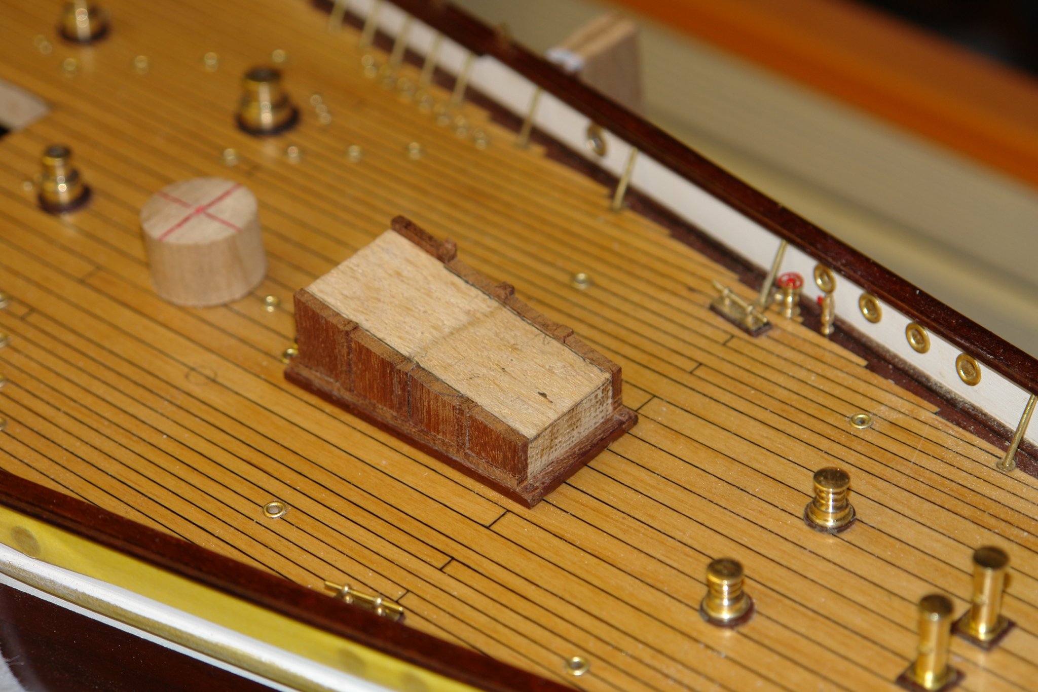
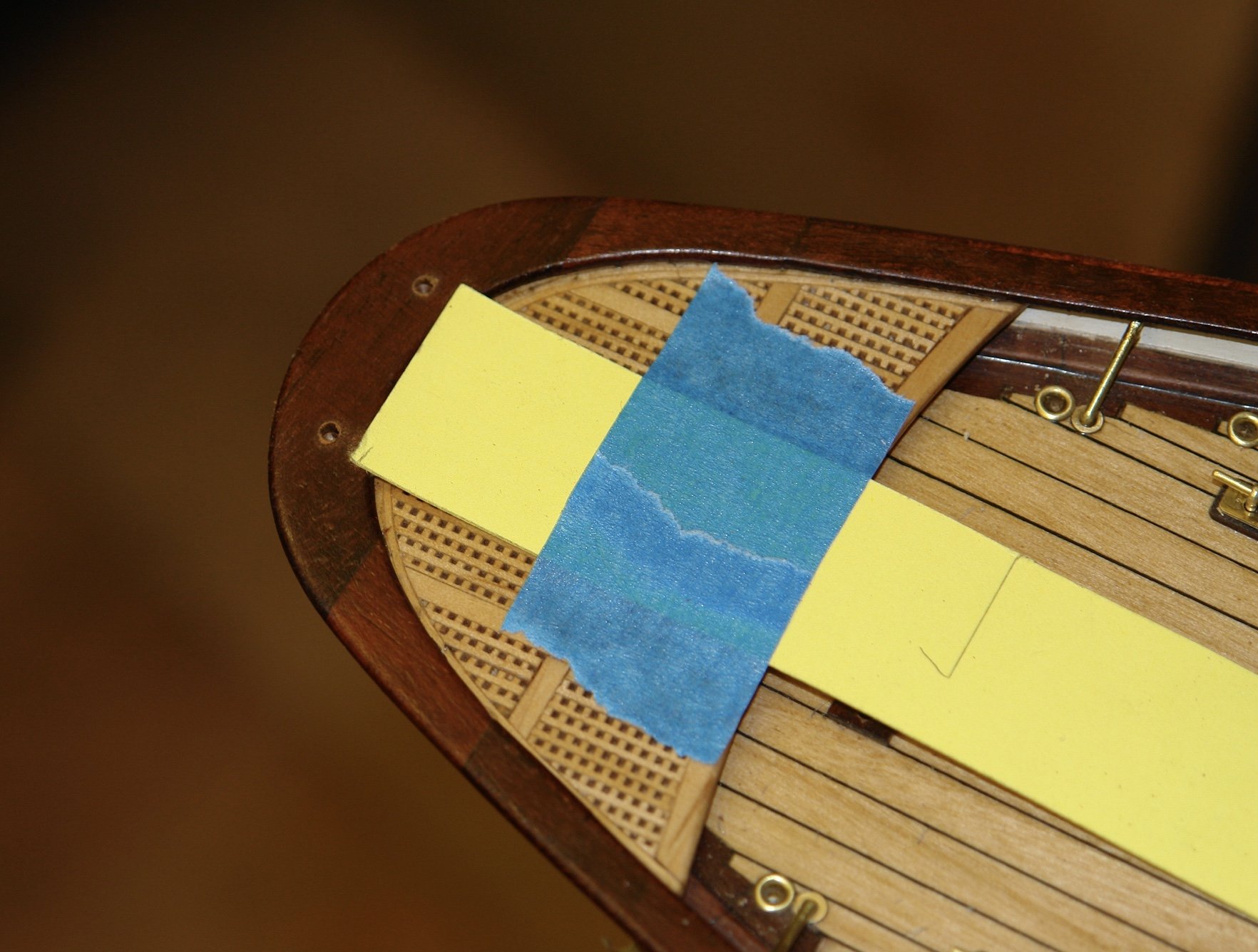
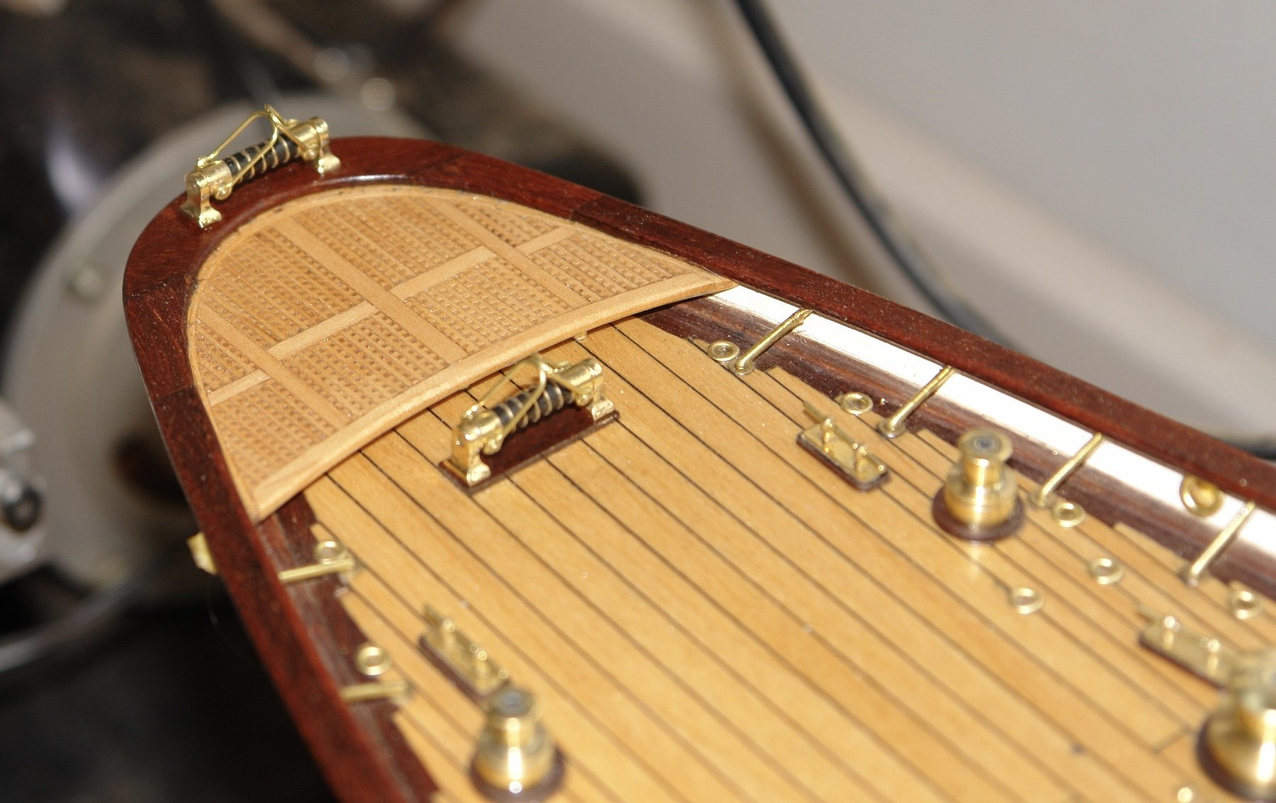
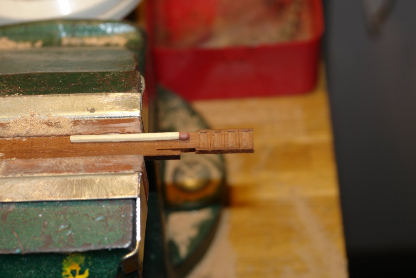
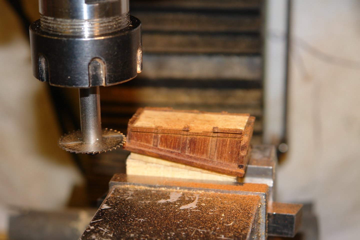
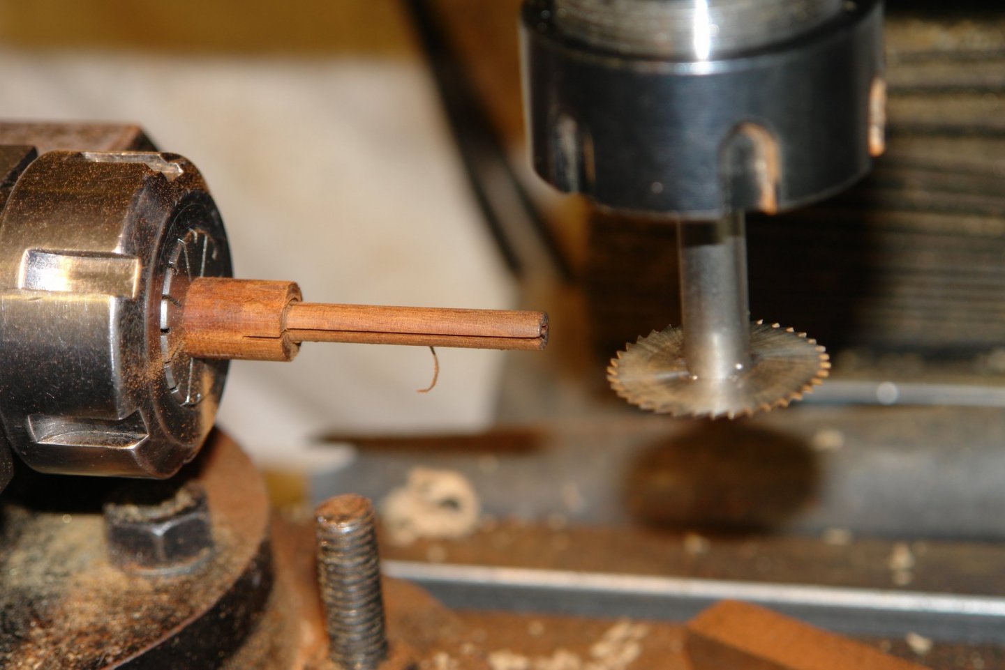
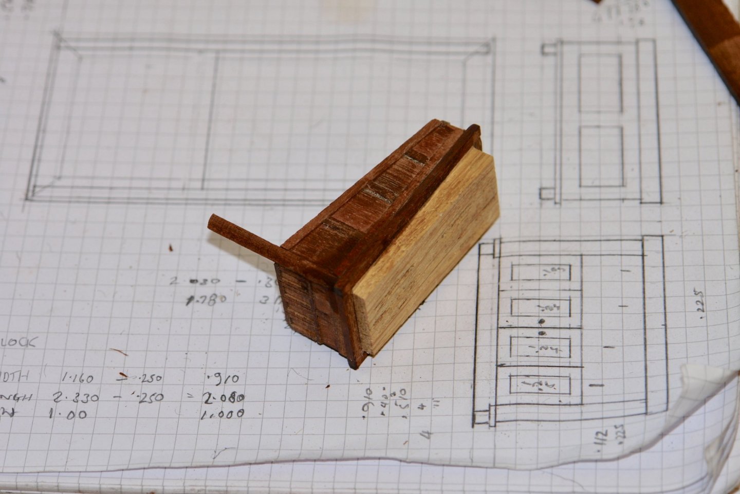
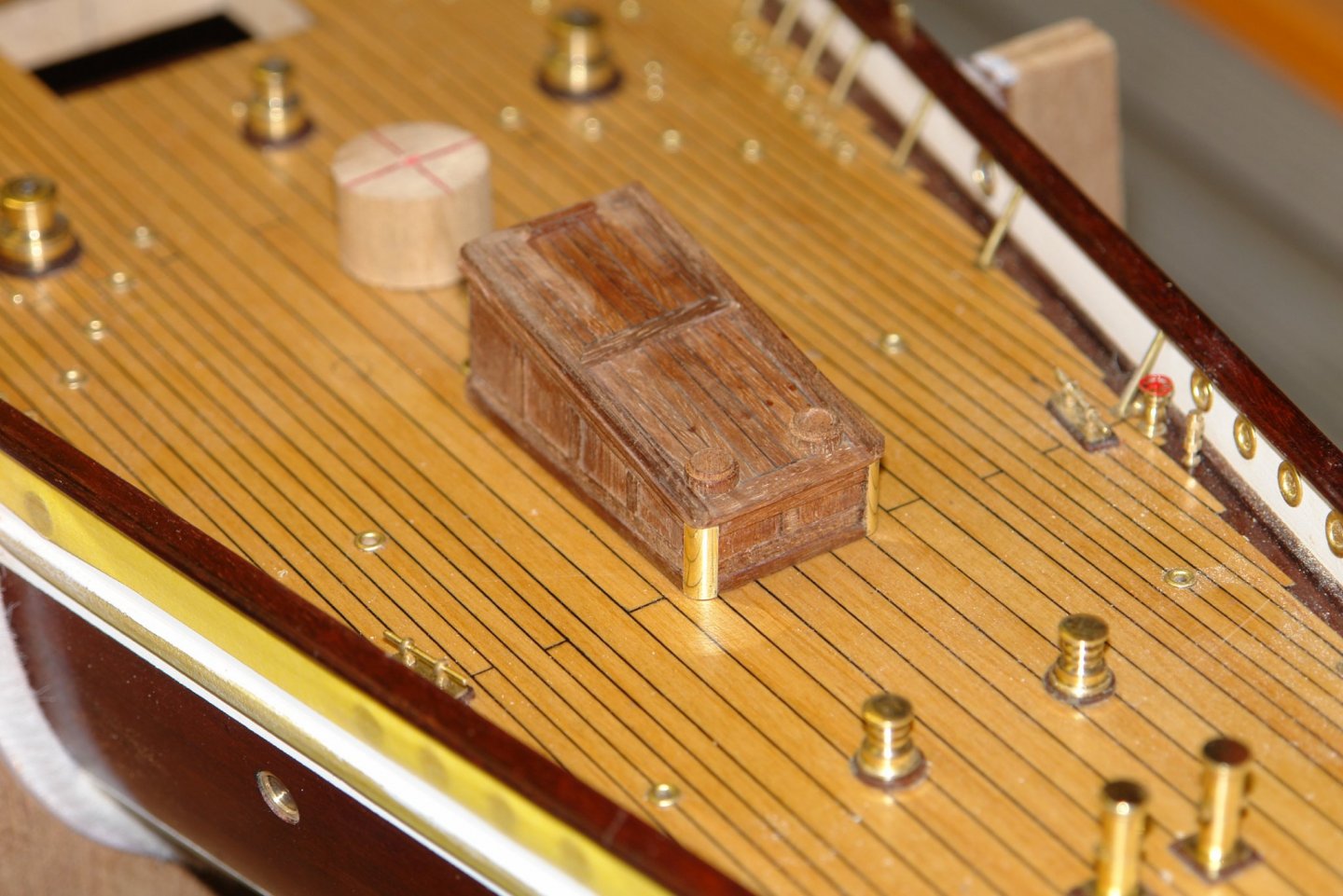
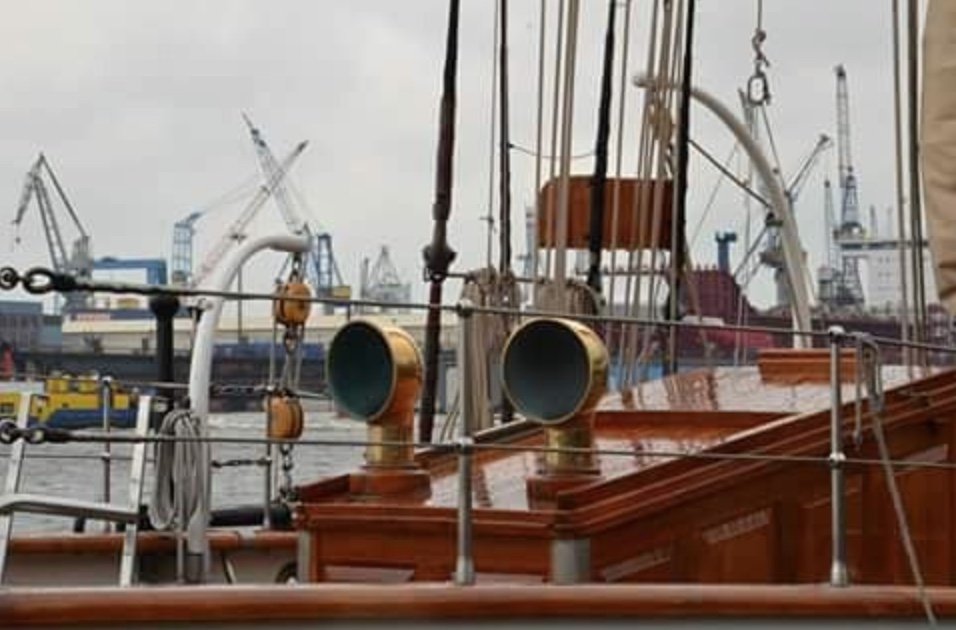
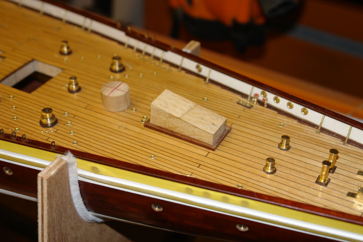
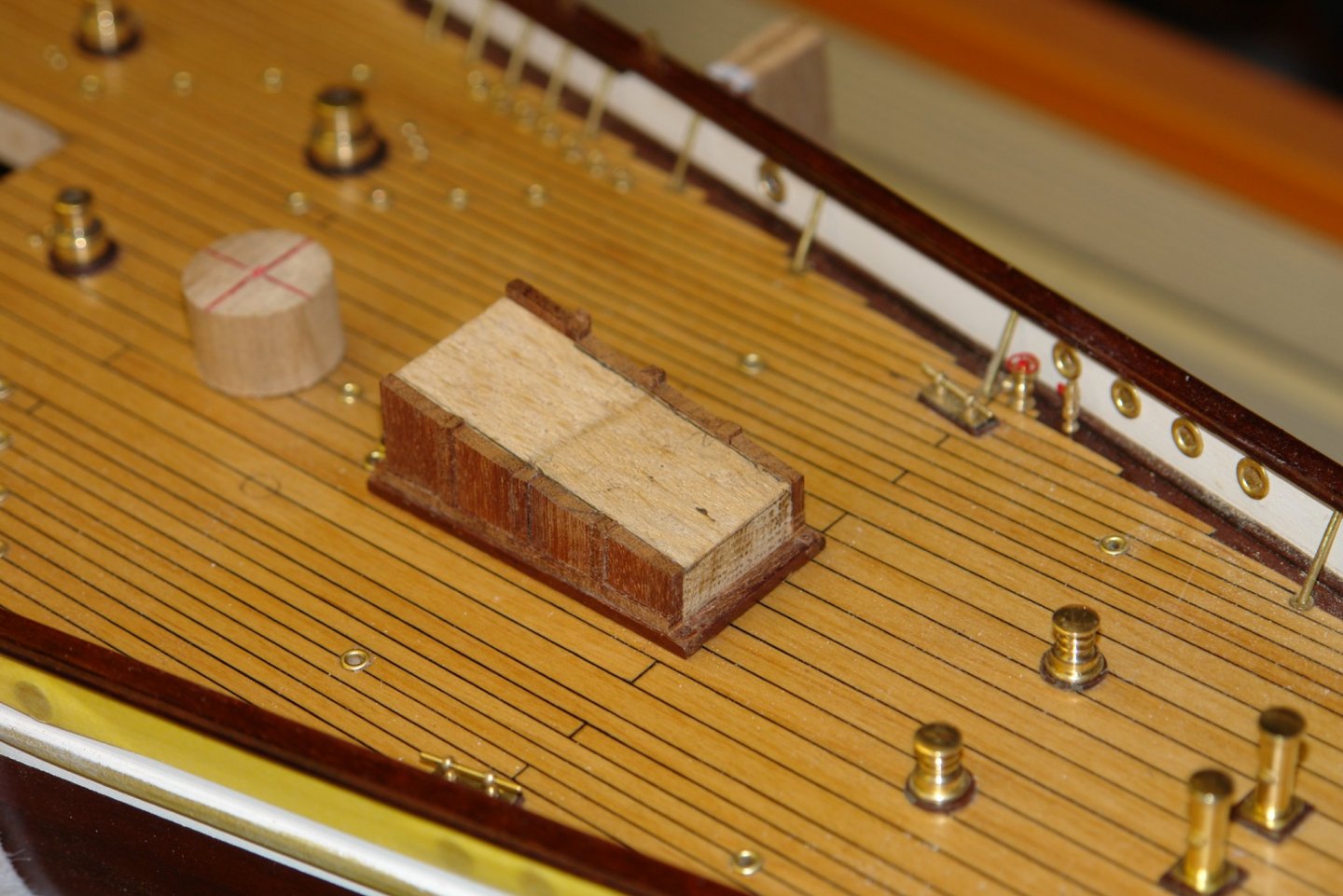
The rear face of the deckhouse has bifold doors - at scale size these are quite small and I won't be making hinges. The 4 door are made as a strip. Together with associated panels they were glued on to the core. The side panels were left over long and were cut back to size on the mill. The top plank was glued in place where the panels had been cut back and then a piece of mahogany was turned and slit to form the corner pieces. The top was constructed from 0.1" wide by .060" thick planks separated by .006" card to simulate the caulking. The hatch top cover was similarly made. The tape is protecting the front corners that were made from turned brass rod. This reinforcement is included because of the proximity of the anchor chain. 2 holes were drilled to take the vents. Mahogany inserts were turned to simulate the plinths on which the vents sit.


-
Eberhard, that is some way off yet. I have a lot to make and I will make them as a batch. I do have a plan of sorts. Seems the most sensible interpretation Mark - thank you to both of you.
-
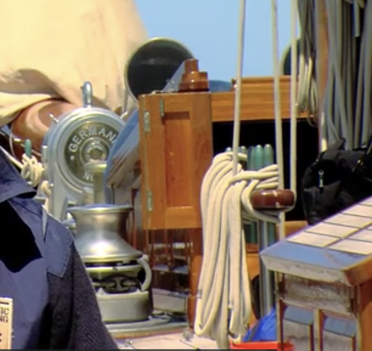
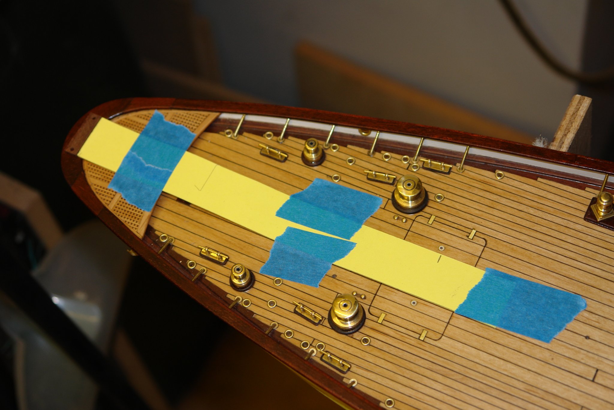
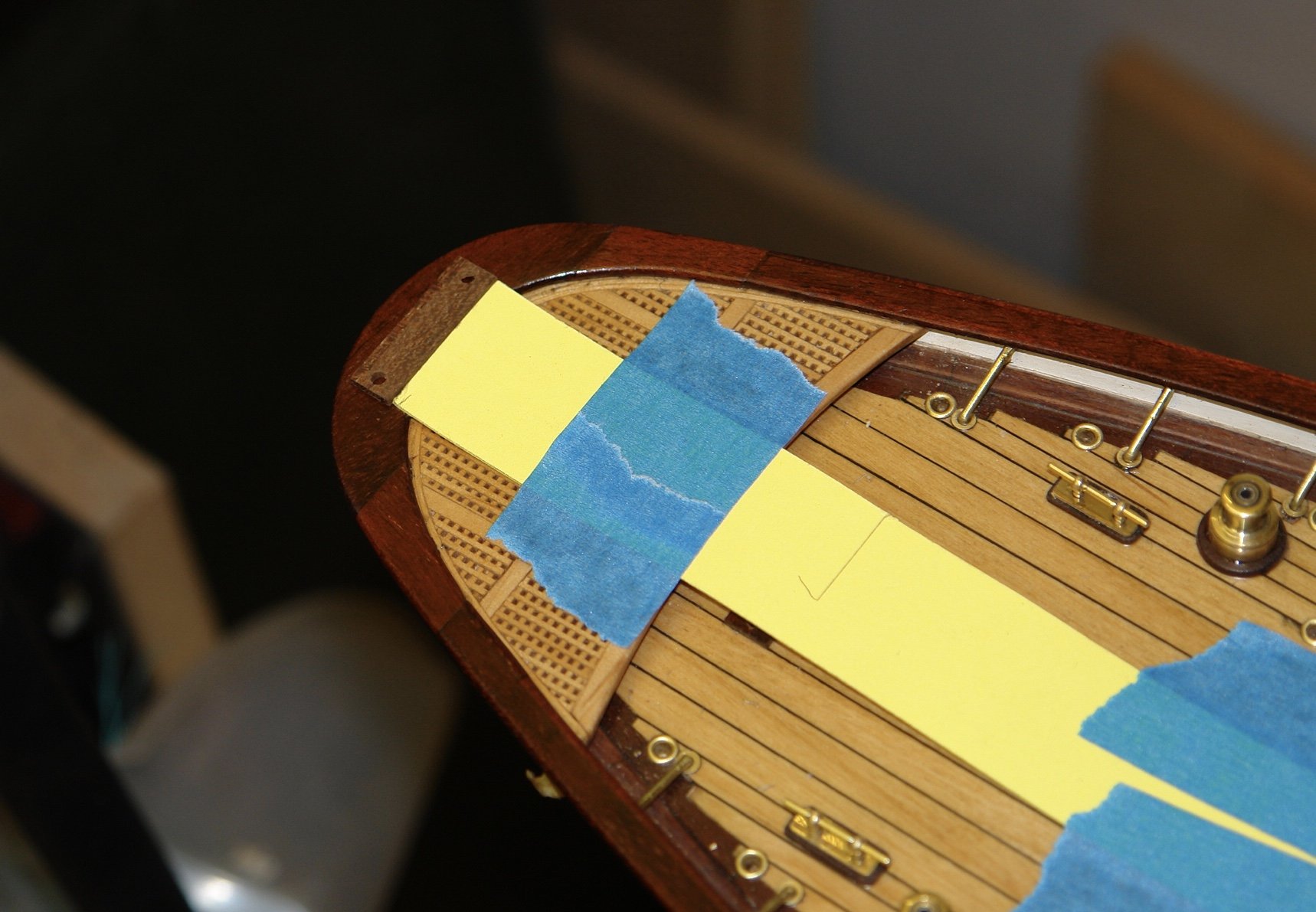
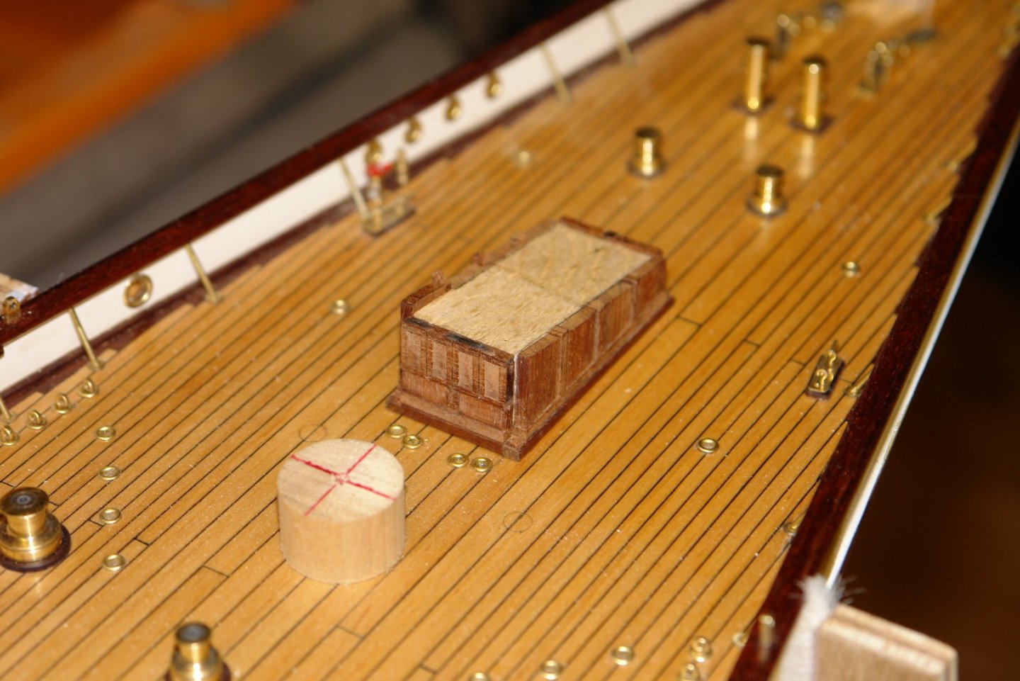
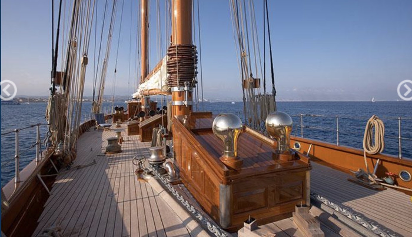
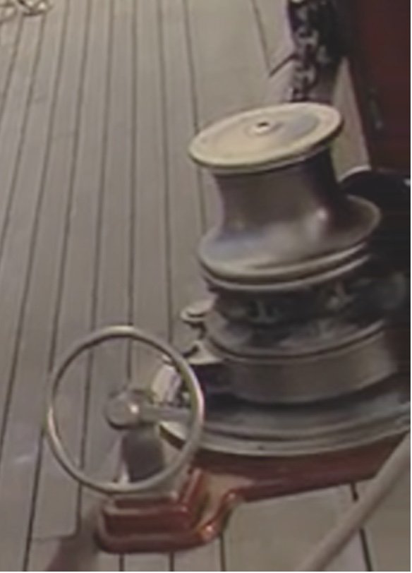
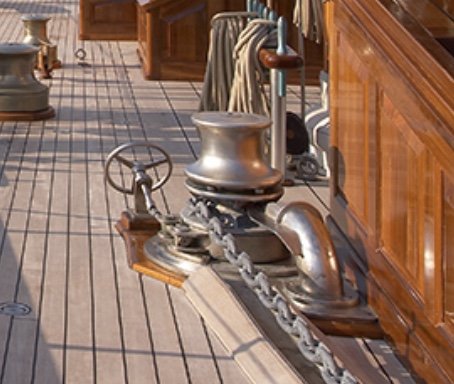
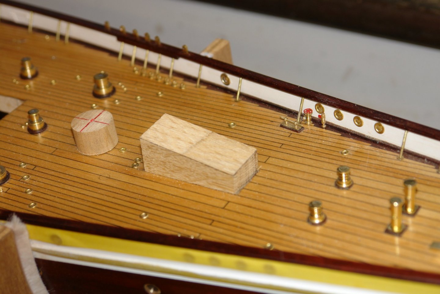
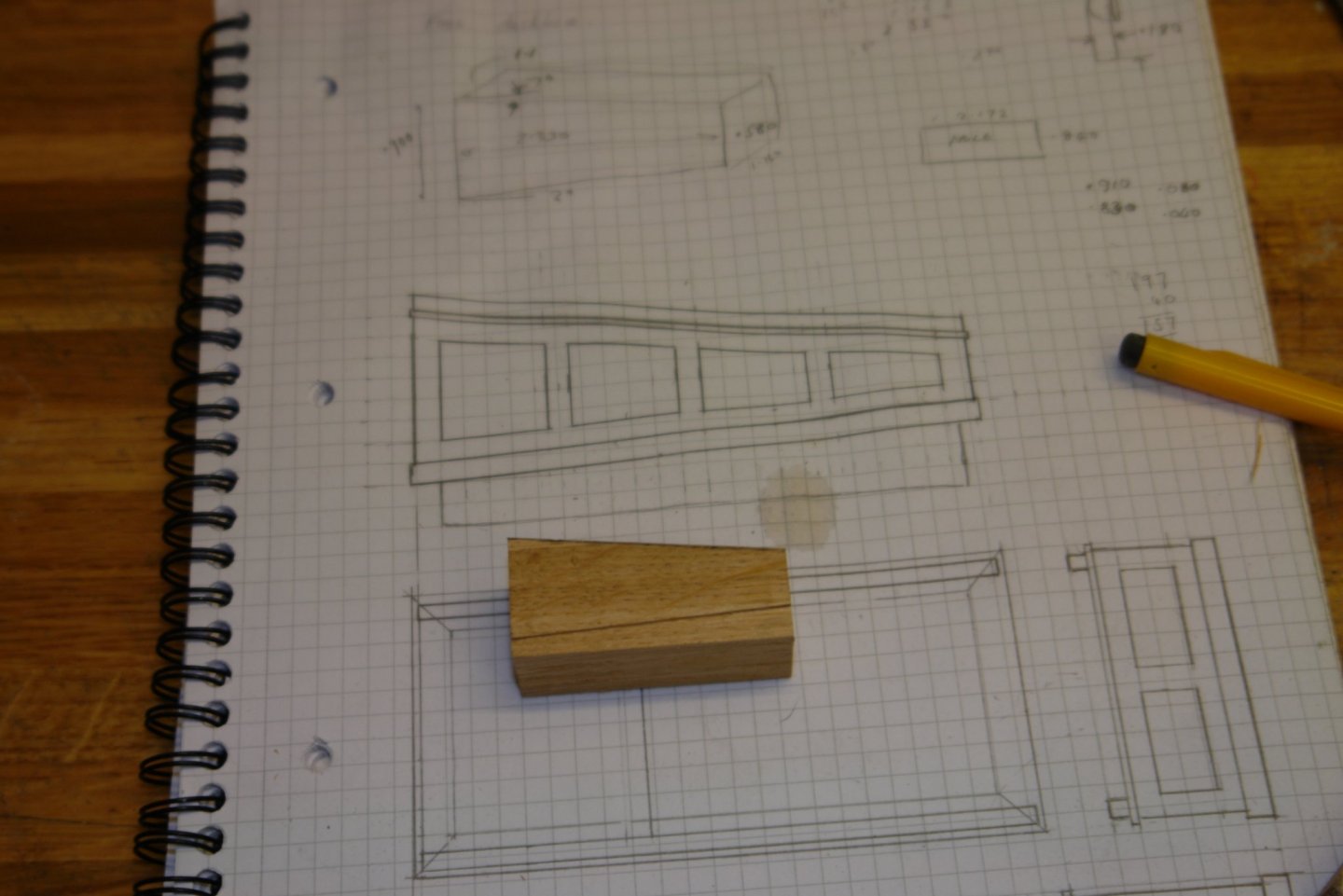
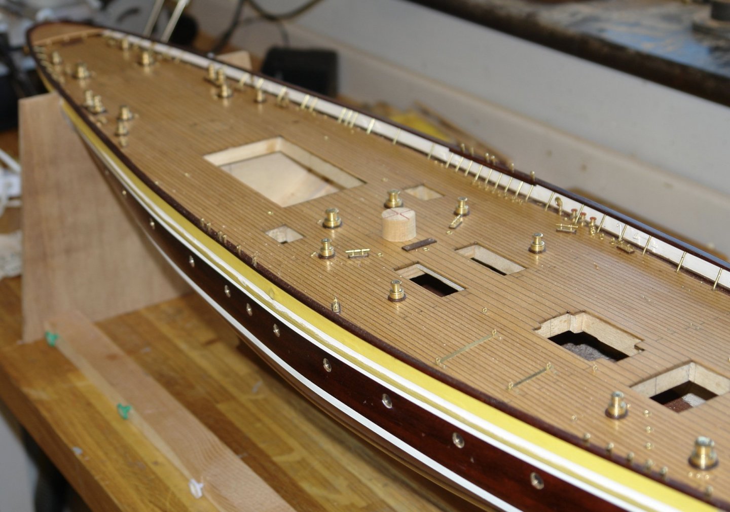
Thank you for the comments Paul, Druxey, Richard and Pat. Also thanks for all the likes. I am continuing working on the foredeck specifically I am moving on to the foremost deckhouse and the anchor winches on either side of it. I am able to get basic sizing data for the deckhouse from the small plans downloaded from the web. I also have good photographic information:- With this information I was able to create sketch plans. I don't have any detail of the inside of the hatch so I am modelling it with the hatch doors closed. I am building the mahogany panelling on a solid oak core. The core was shaped on the mill. Planks were cut and glued in place at the deck level. Then individual panels and frames were cut to clad each side. The panel definition isn't good in this shot - it is actually much better in the flesh and even better when painted with poly on a test piece that I made. The next post will show this.


-
Just catching up Richard. The woodwork continues to look impressive and the metalwork is excellent.
-
Very interesting Eberhard, I particularly liked the simplicity of the human powered rotation and elevation gear below deck. Do you know how many crew were needed to man the gun?
-
Eberhard - it was etched - from my bits bin. I will have to make a couple of hand wheels in the near future for the anchor capstan brake as I don't have anything the right size / shape.
-
I enjoyed catching up on all the fit out details Geert. It is a pity this build is nearing its end.
-
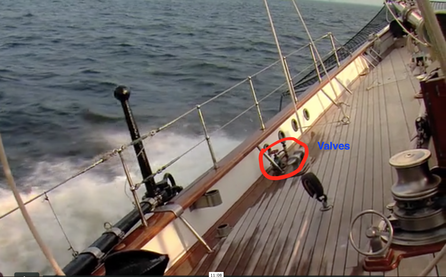
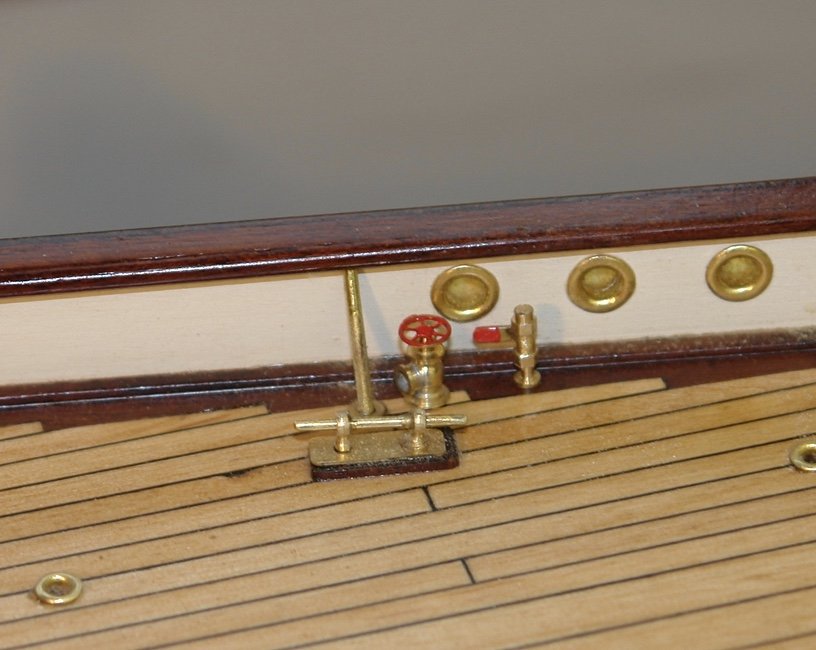
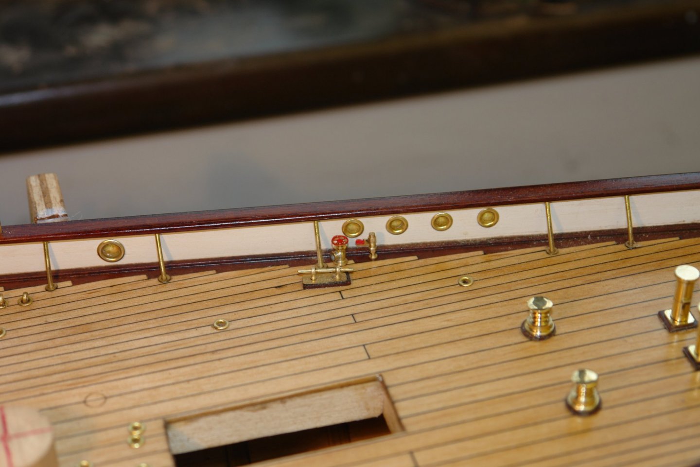
Thank you Richard The weekend was quite productive and I seemed to make reasonable progress that I will cover in a couple of posts. It started with a bit of a Arggggh!!!! moment while looking at the next photo. This position is looking forward towards the bow and I had completely missed the 2 valves indicated. So the weekend stated with a valve making diversion. That done I mounted the 3 shock absorbers for the main and foremast booms. The one on the stern rail was most tricky with the danger that i would drill through to the underside of the stern. I used card and a wooden template to get the position correct and drilled carefully. All went well. The other 2 were more straightforward. I also made good progress on the foremost deck house. I will post the details over then next couple of days.


-
Very nice work on the blocks, particularly as they are freehand. Work can be a bind but retirement comes around eventually.
-
Eberhard - you may be right and as I was going to build based on this interpretation I should be ok. Druxey/John - thank you
-
She is coming along rather quickly Paul. Your shed is clearly warmer than mine.
-
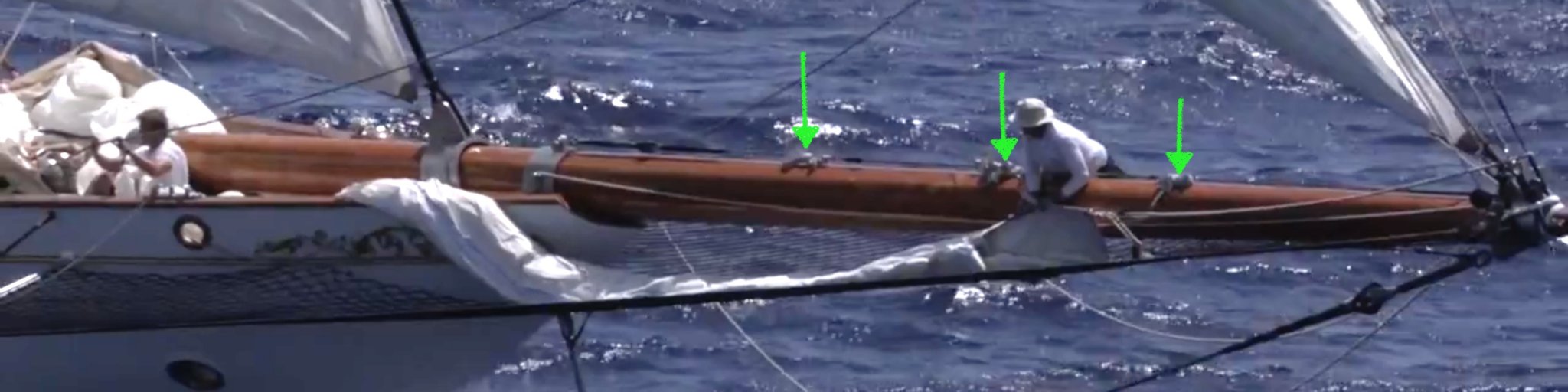
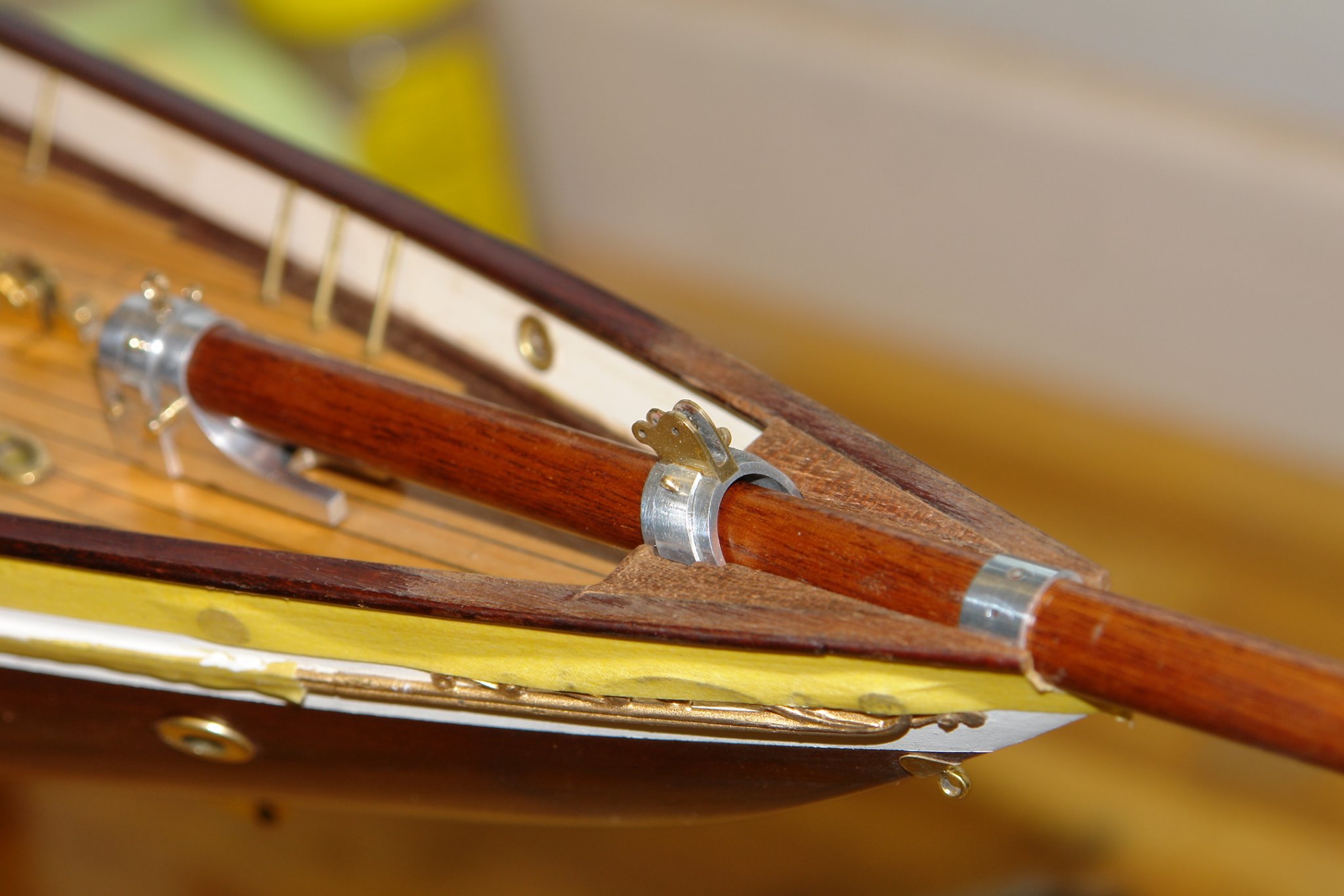
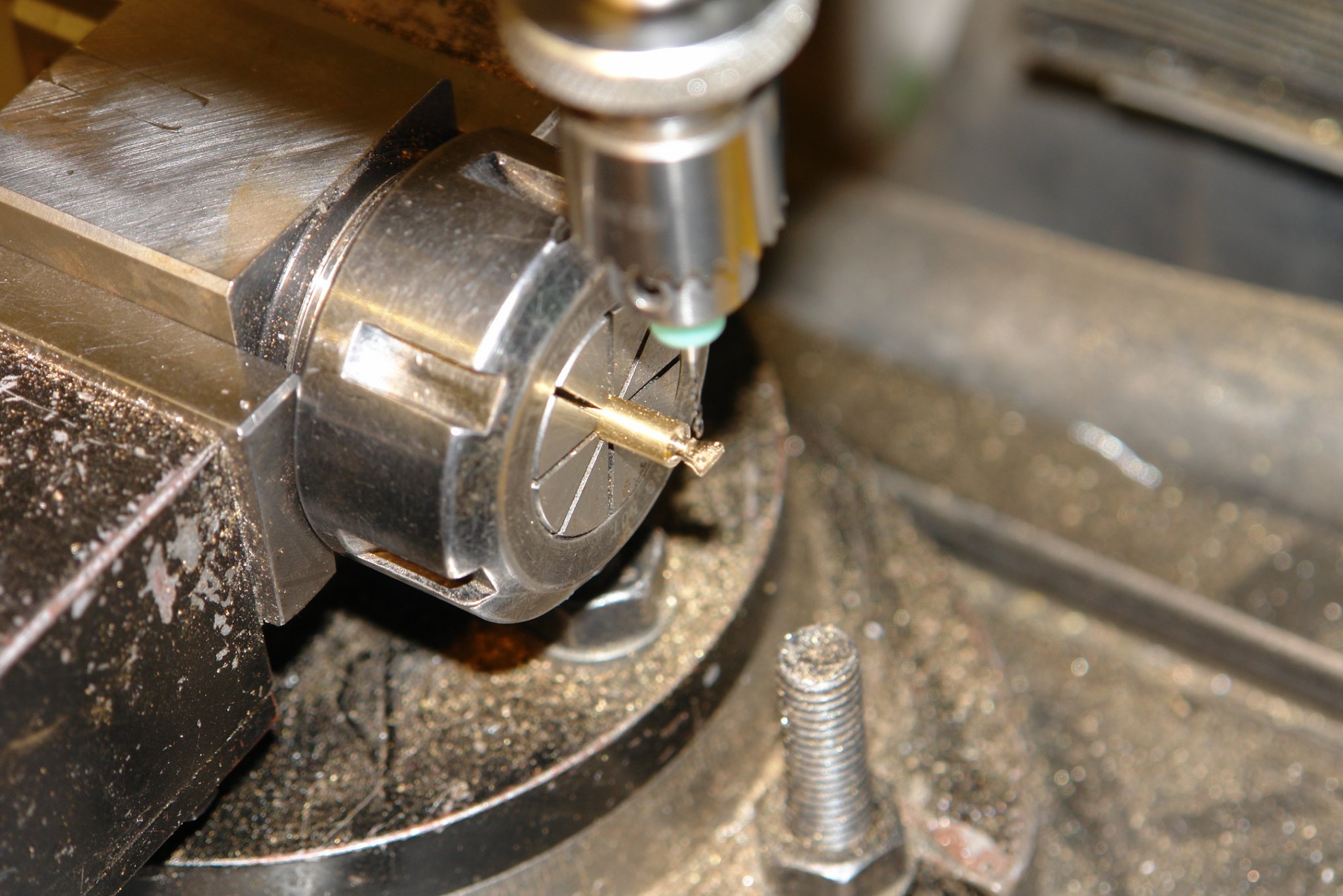
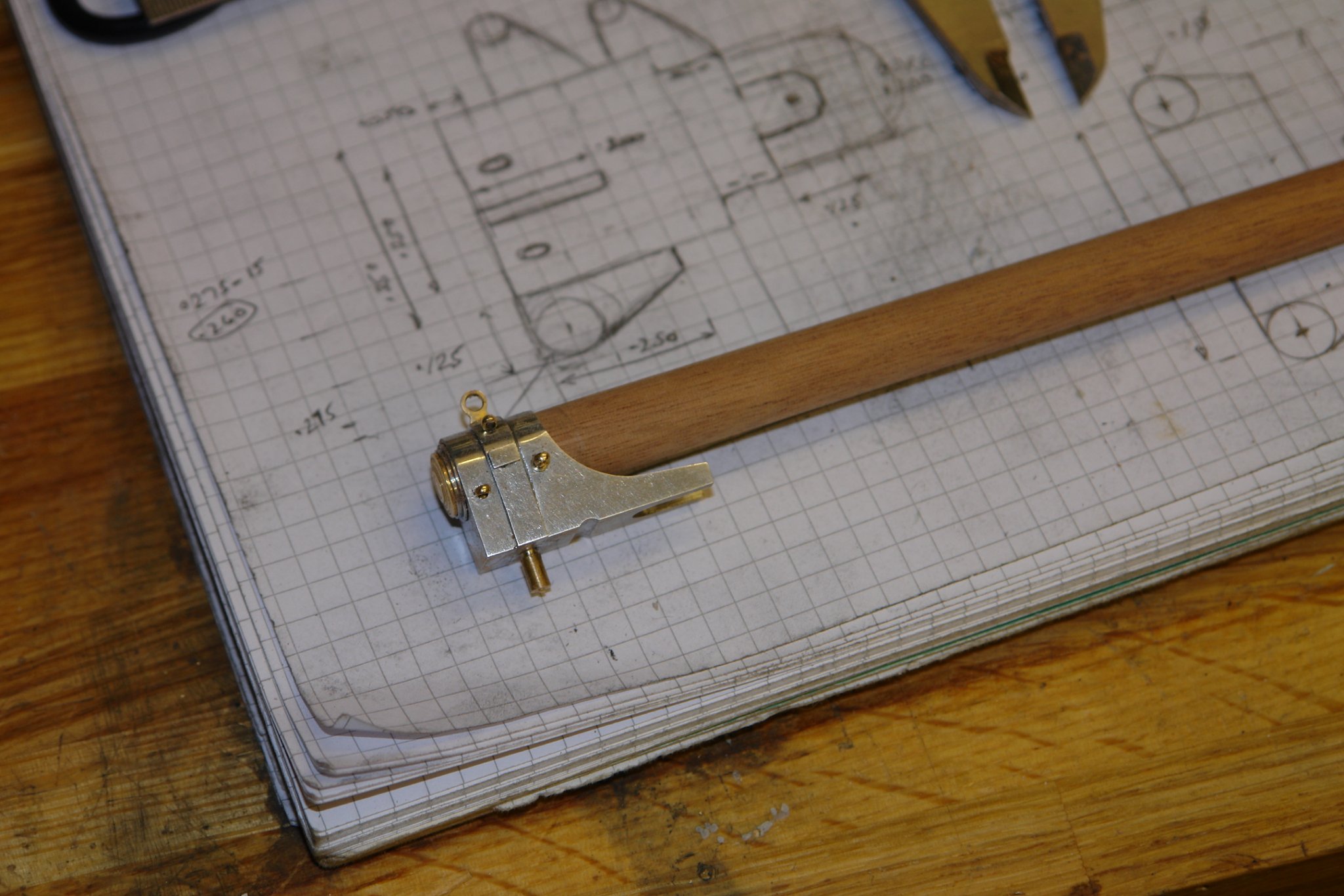
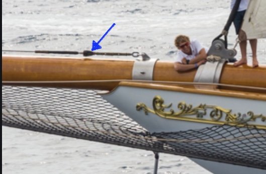
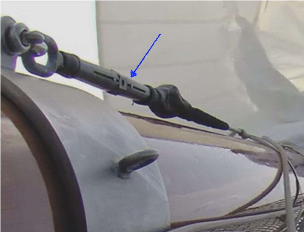
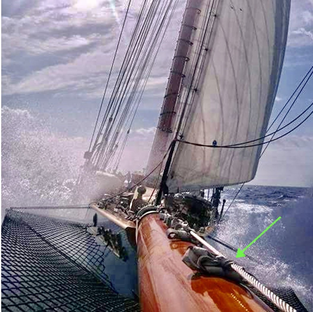
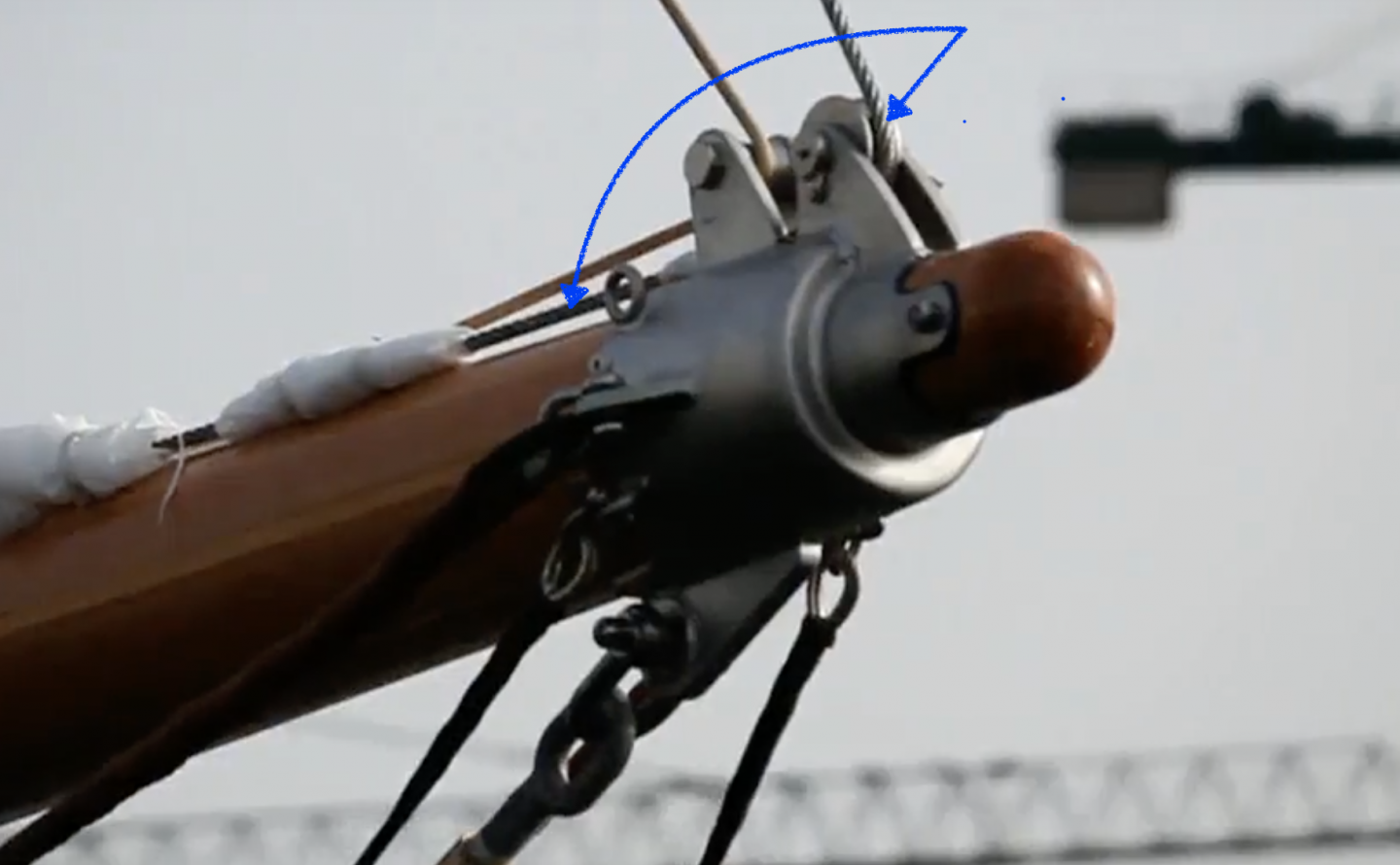
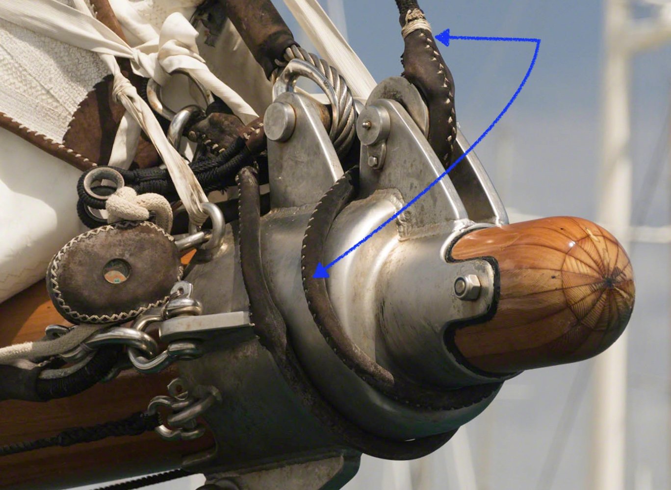
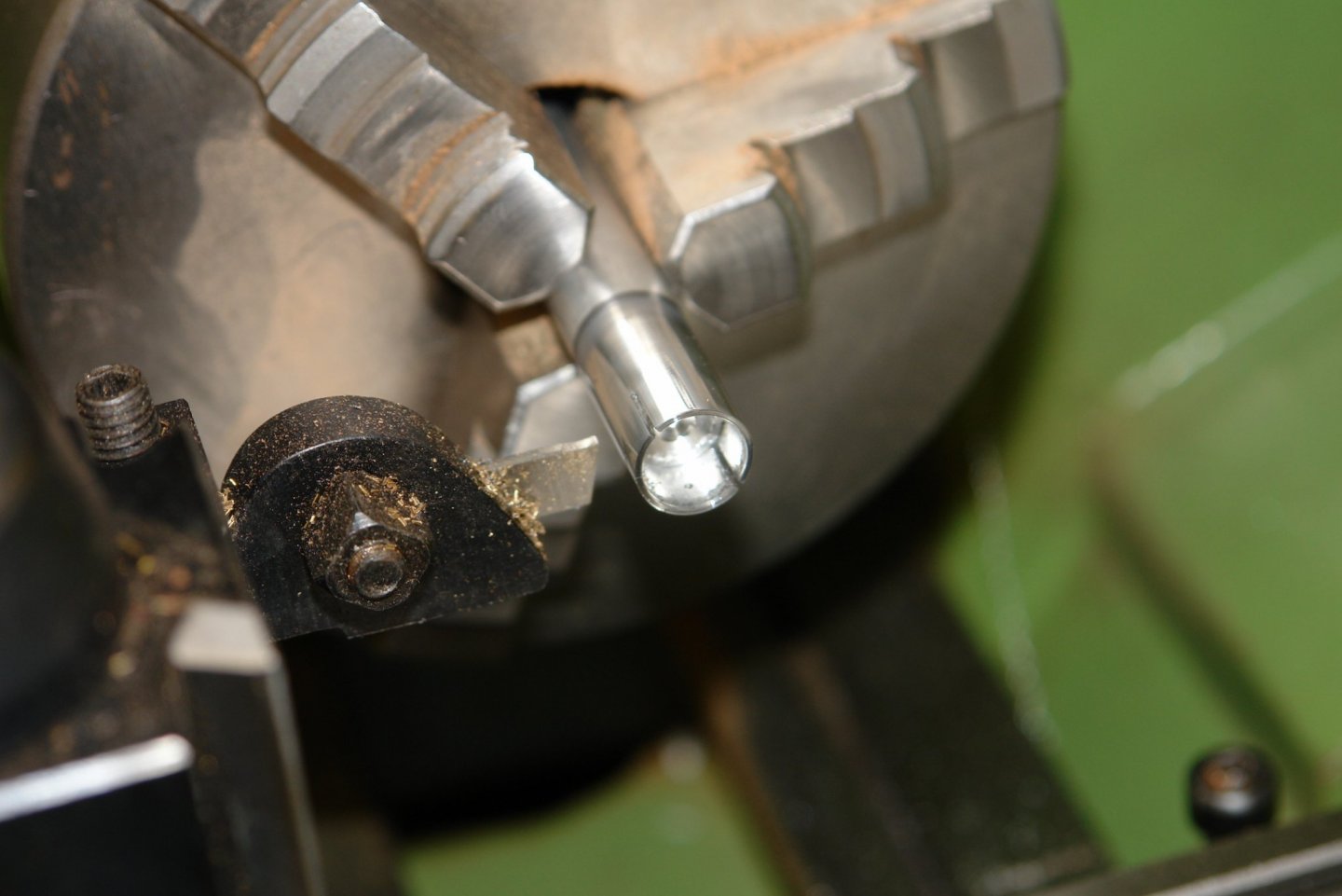
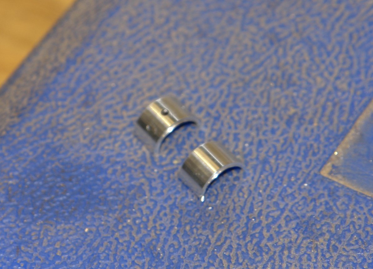
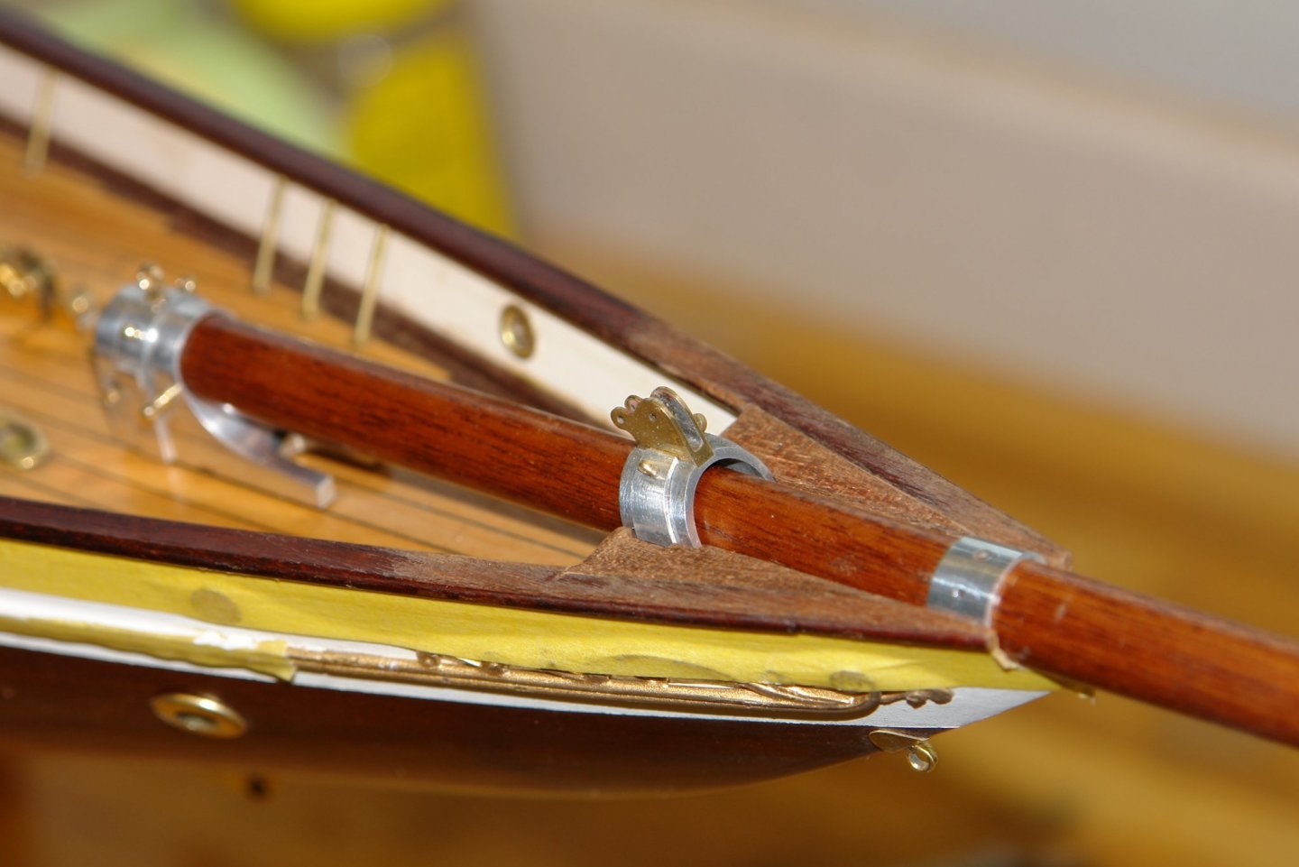
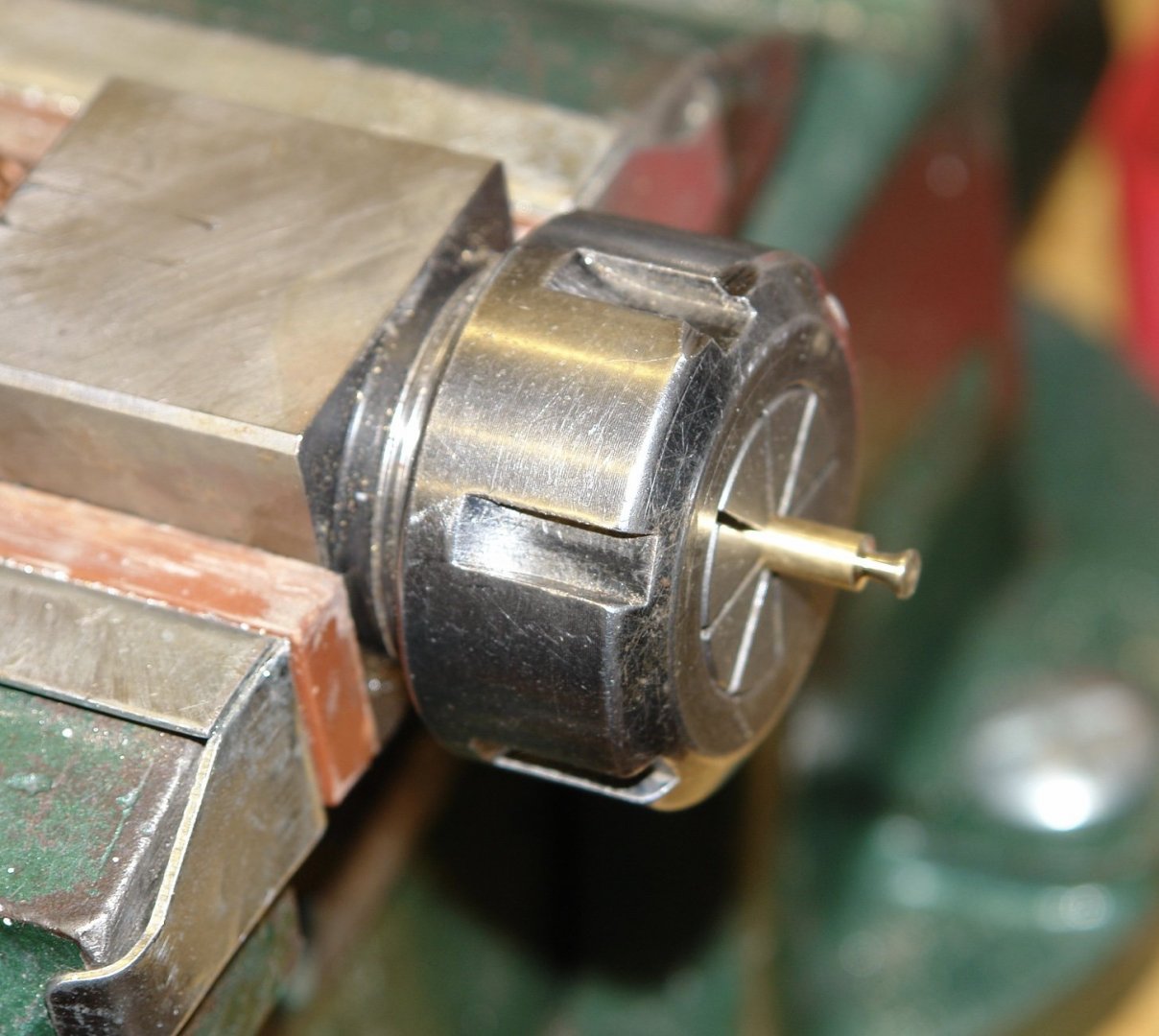
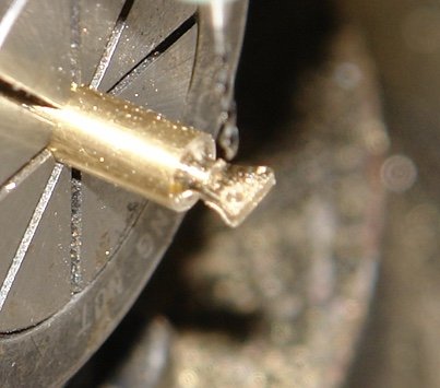
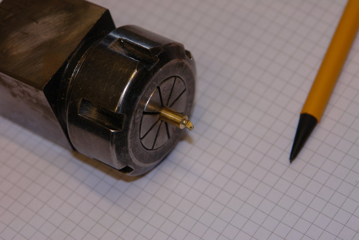
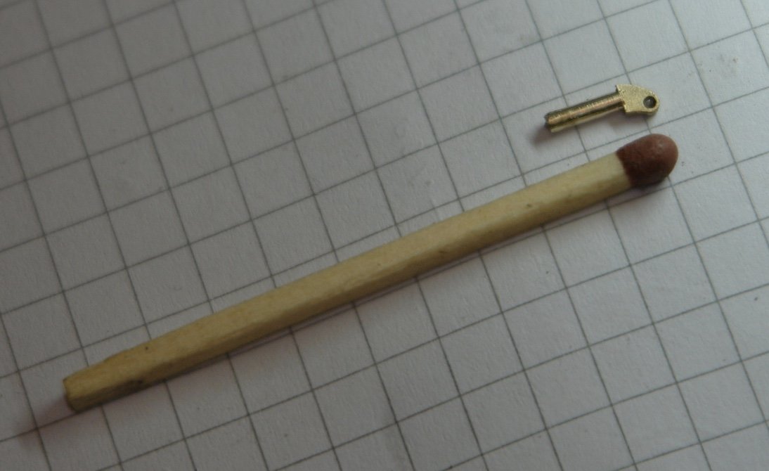
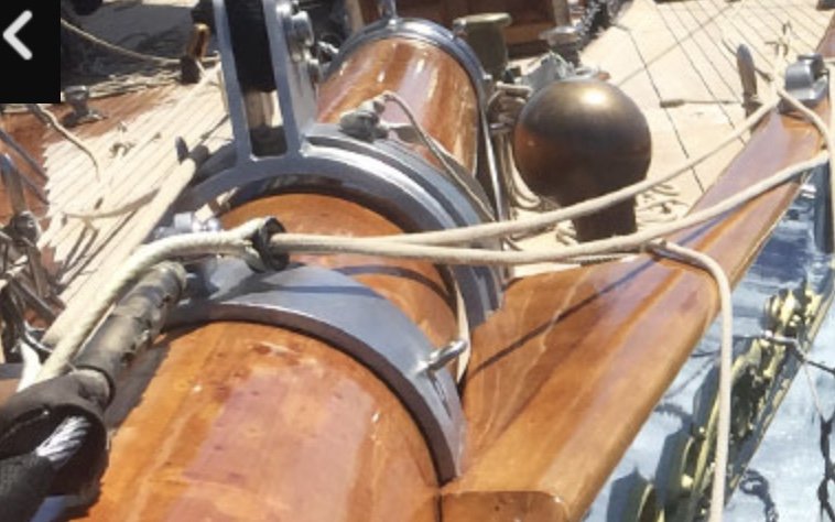
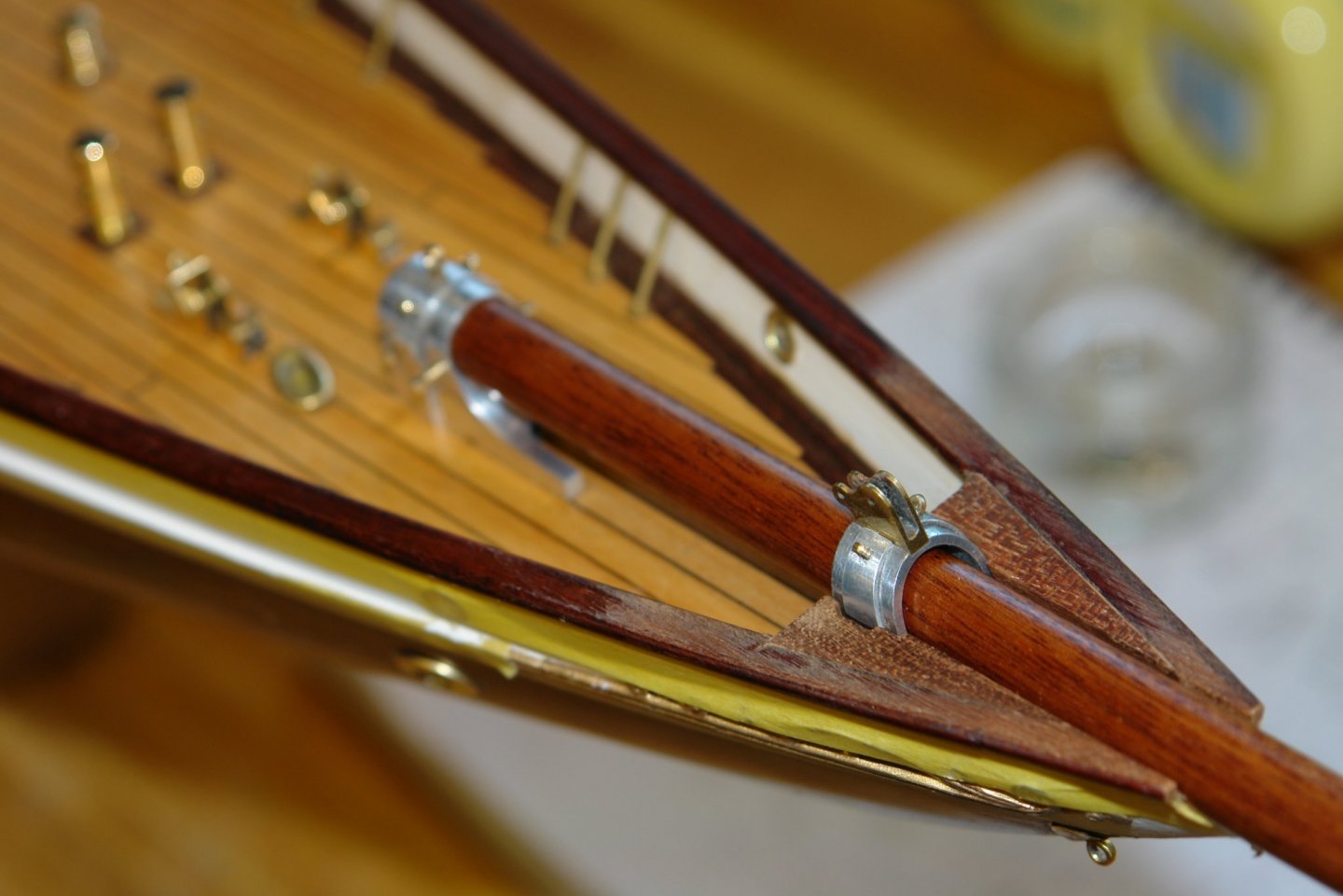
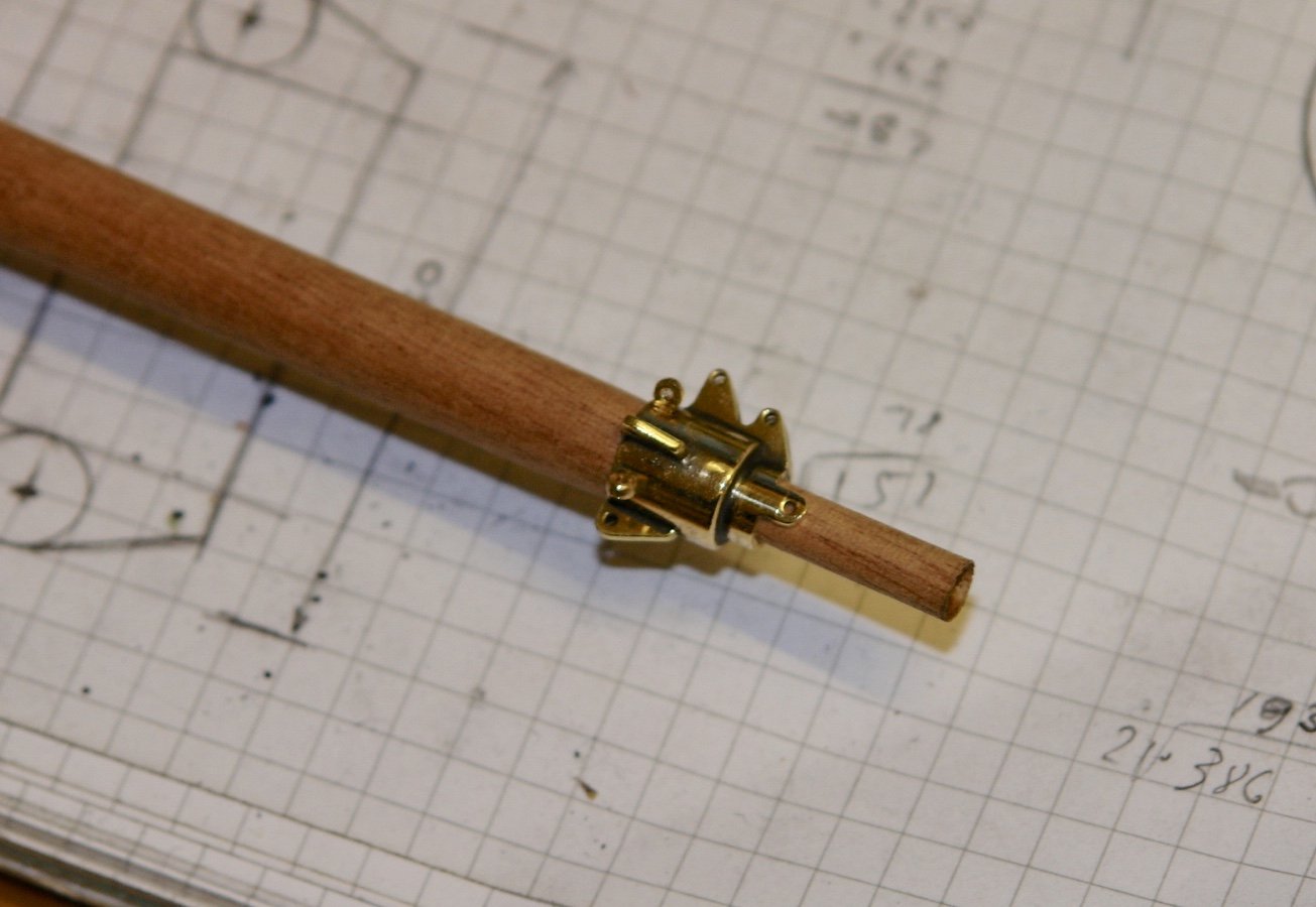
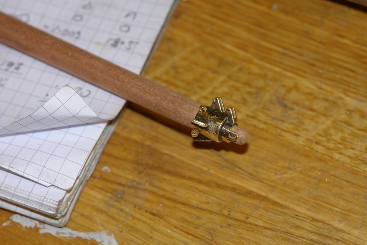
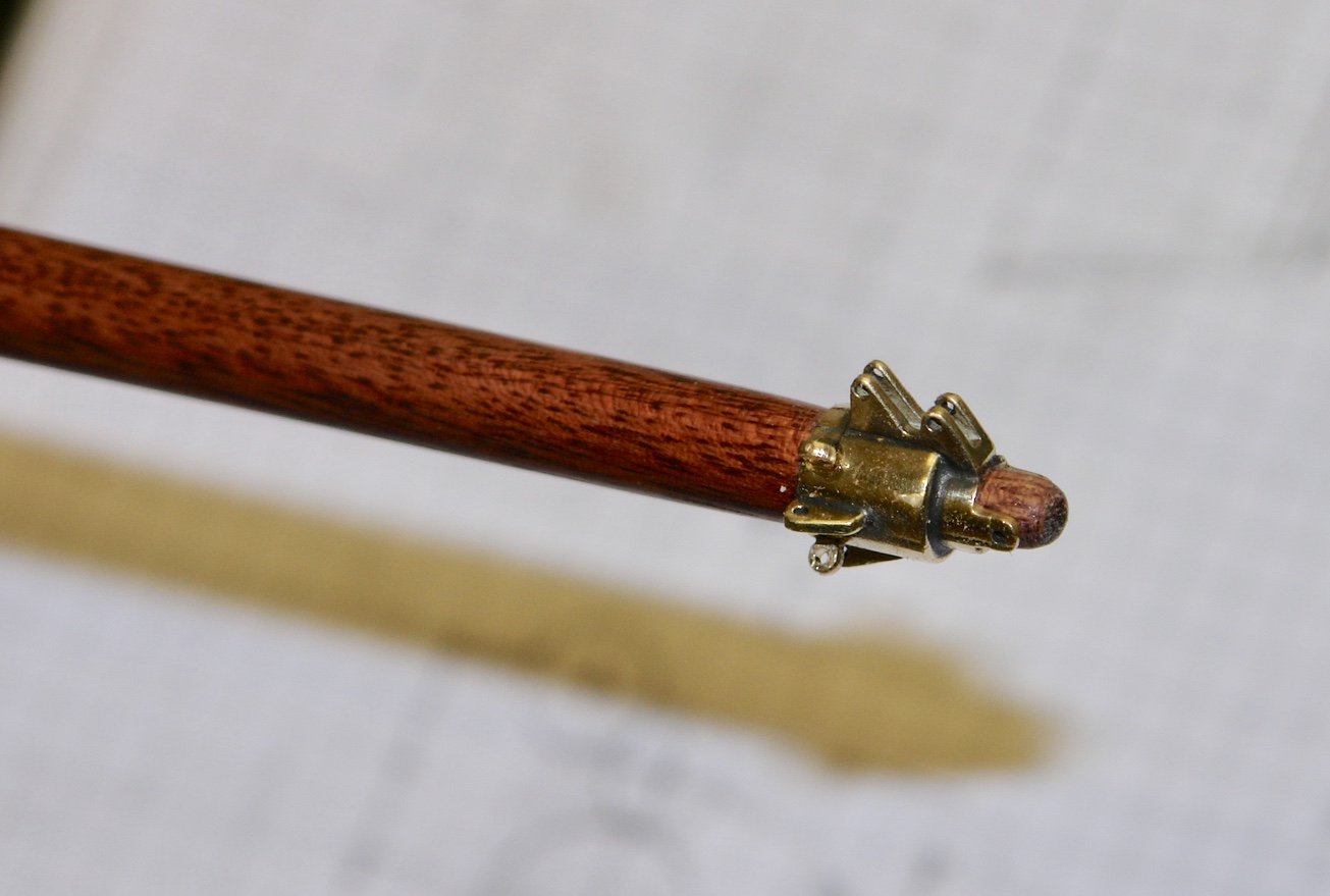
Thank you Shipman, Druxey, Keith, John, Richard and Pat for your much appreciated comments, and thank you to everyone who has visited and or liked my log. Shed work has been severely disrupted recently by a influx of house guests, fortunately they have now gone and I can get back to work. I did manage to do a bit of investigation during their stay and also a minuscule amount of manufacturing. So here are the results:- I did a bit of a review of the bowsprit detail as shown on various photographs. I still needed to make the mast band as per the next photo:- This band anchors the turnbuckle which tensions the forestay:- The anchoring lug leans forward. The turnbuckle detail can be seen in the next photo:- The stay runs out along the bowsprit and a number of features seem to be interposed between the stay and bowsprit:- It took some time to understand what these were but eventually I dug up the following photo:- I think what I am looking at is odd bits of strapping/sailcloth wedged in place to prevent damage to the bowsprit. If anyone has a better interpretation please let me know. The forestay itself is also a bit of an enigma. In the following photo you can see the stay rounding a sheave before heading skyward:- In another (I think more recent) photo the forestay seems to be looped around the cranse iron and presumably the turnbuckle has become redundant????? Anyway I think I am going with the earlier arrangement. As for the bowsprit hoop it was tuned from 1/2" rod and then drilled with 3 holes before being cut in half and parted it off. I decided that the lower half of the ring could be omitted (as it can not be seen). This makes assembly simpler. The forward leaning anchoring lug (mentioned earlier) was turned as a mushroom before being shaved flat on the mill. The off centre hole for attaching the turnbuckle was then drilled. The lug was then freehand filed to shape and a stem turned for mounting through the bowsprit hoop. Hopeful this weekend will be more productive but I must take some time to catch up with all your builds.


-
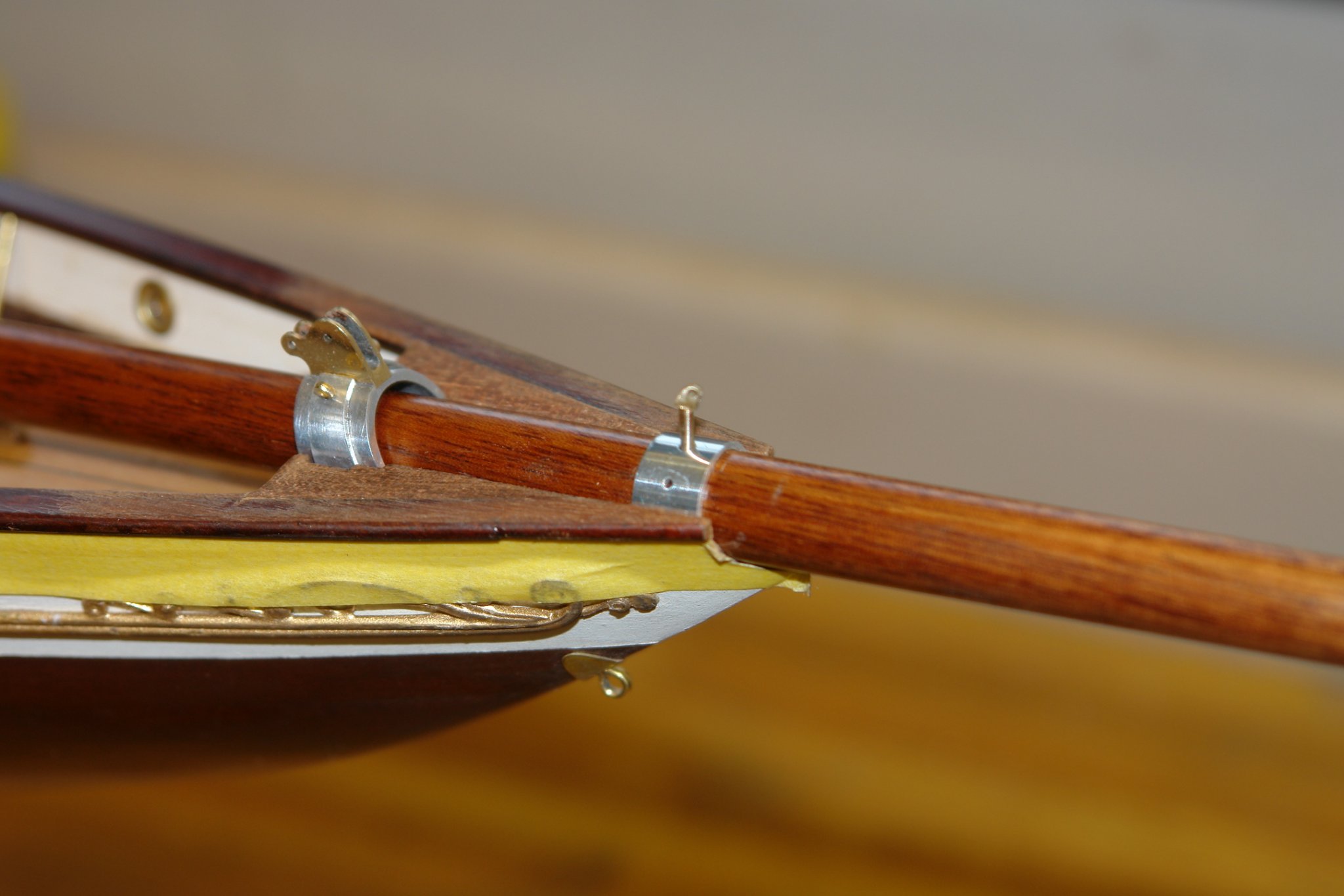
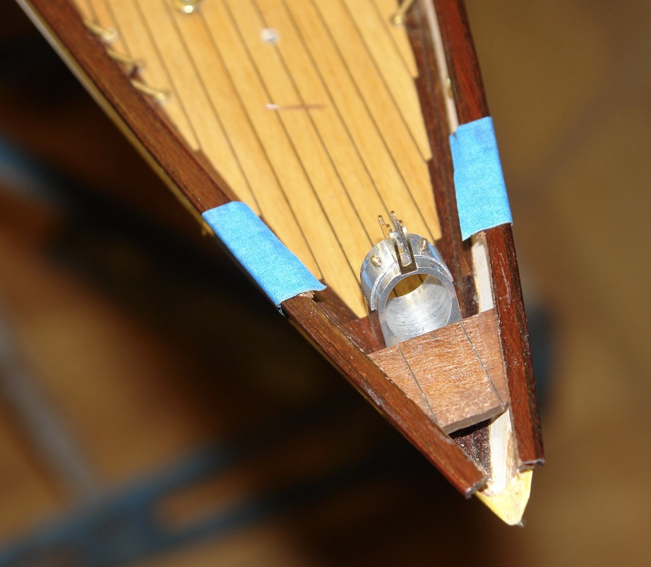
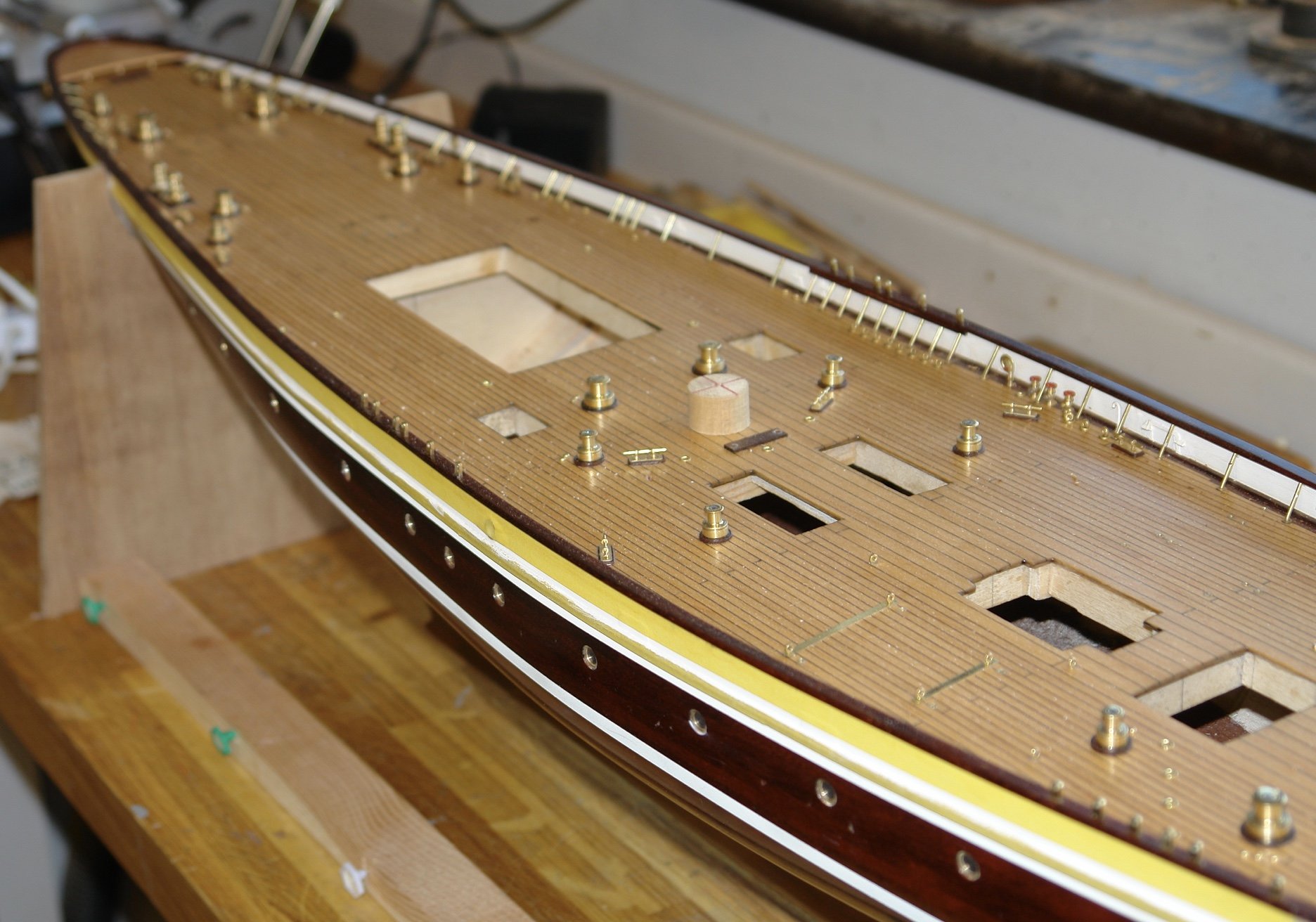
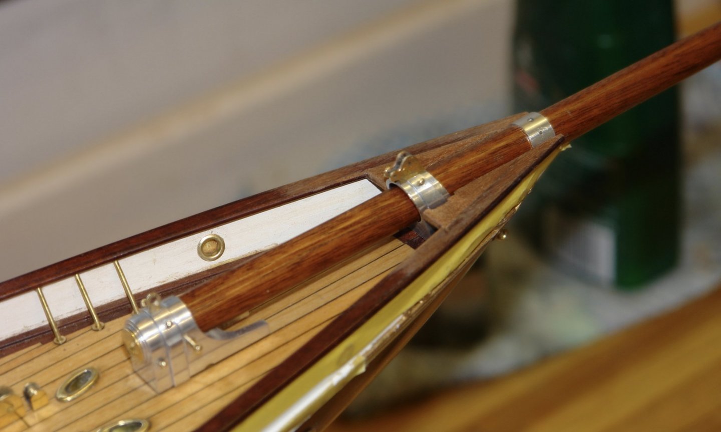
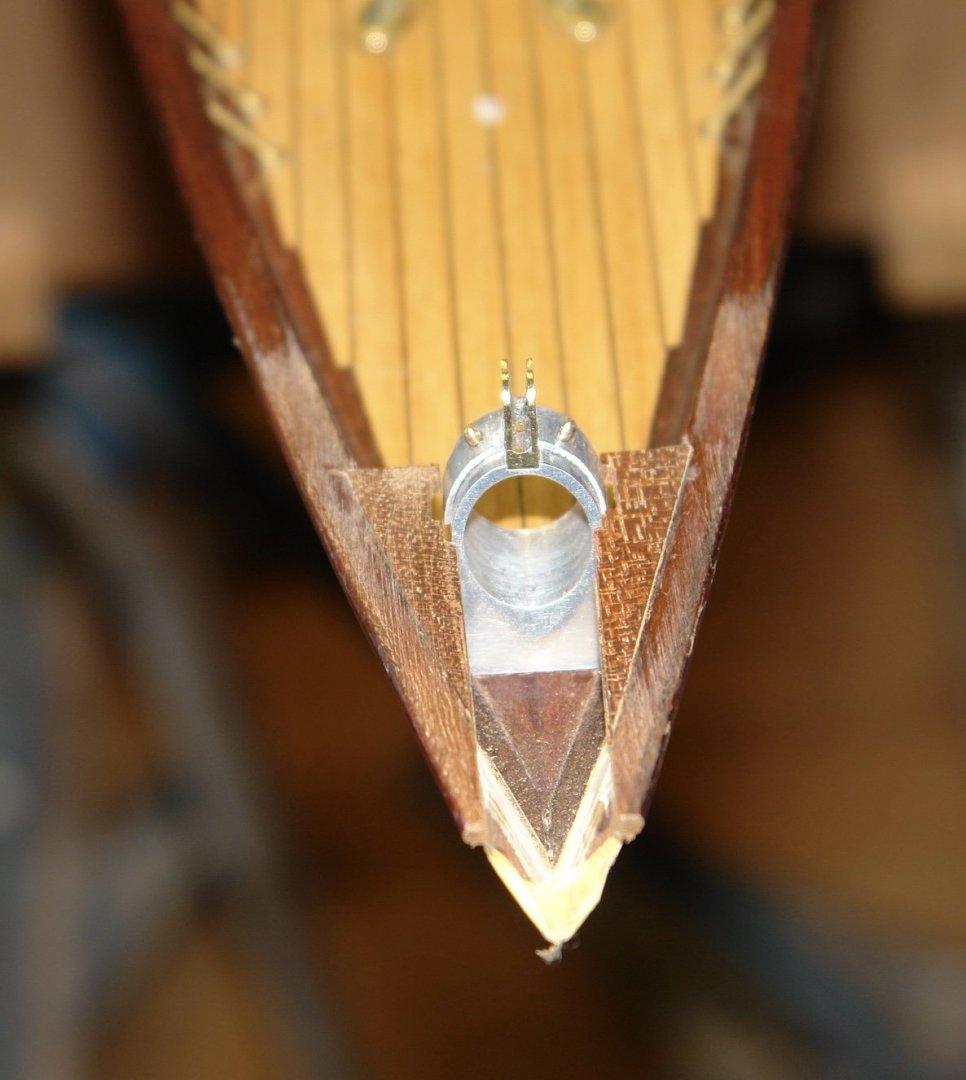
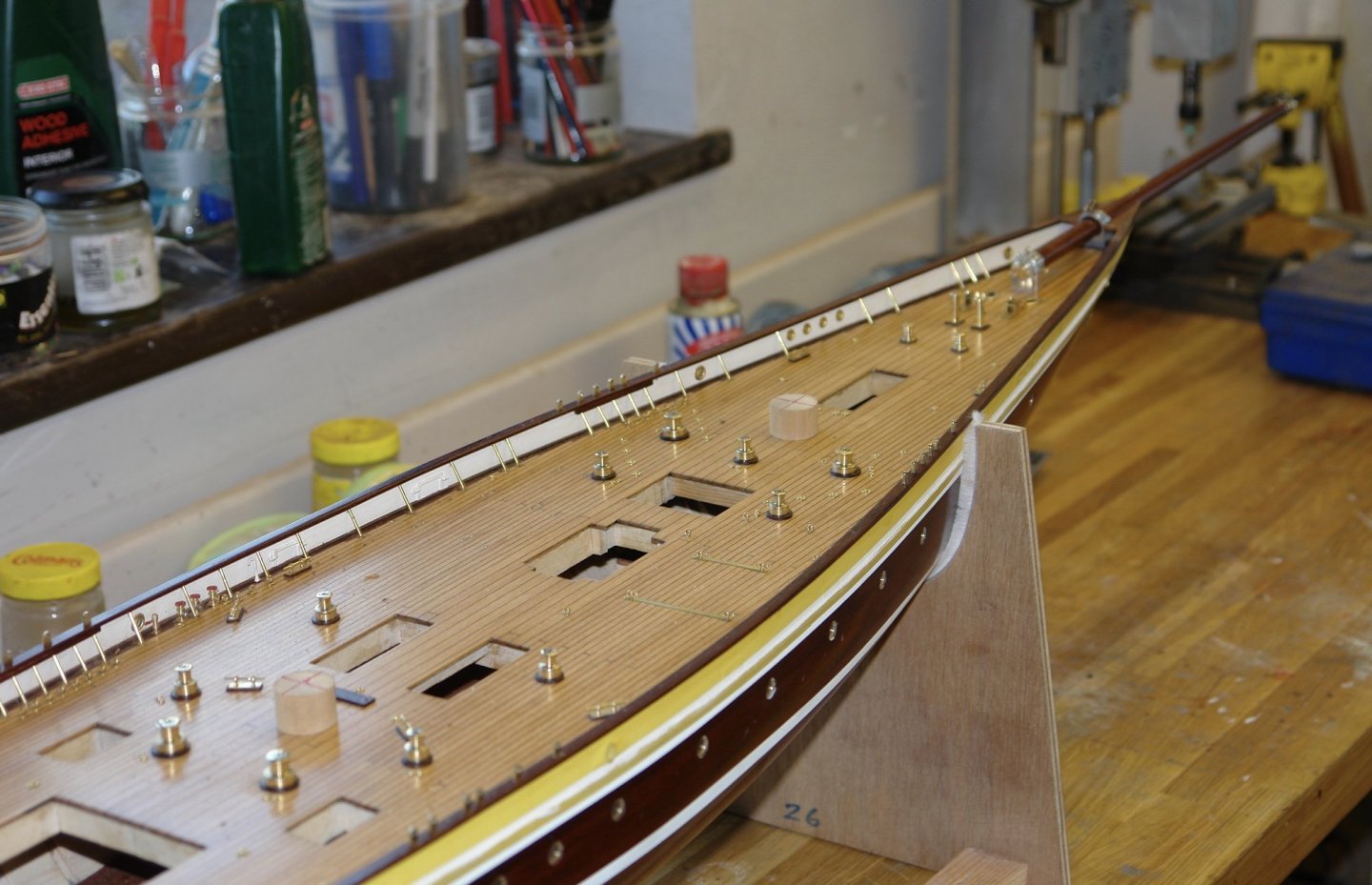
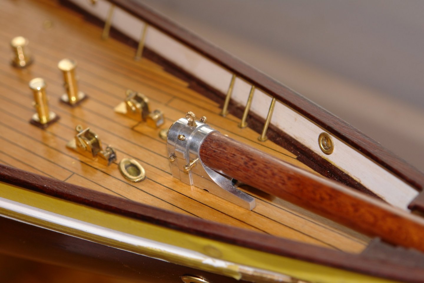
Having made the bowsprit it was time to sort out the bow rails, in particular the the infill between the rail and the bowsprit. From the photo it can be seen that the rails are cut off square at the bow end and that the space between the rail and the bowsprit is filled by an insert. This insert masks the lower half of the bowsprit hoop and the previously made staysail bracket. I started by shaping and inserting a strengthening piece immediately below the level of the rail. The middle section of this needs to be removed so I partly cut it through with a razor saw to make the later removal easier. I made a former to ease the creation of the rail infills. The previously installed capping rails were cut back and the infills were then glued on to the strengthening piece / rails and the middle of the strengthening piece was removed. I then test fitted the bowsprit. Then took a couple of general shots:-

-
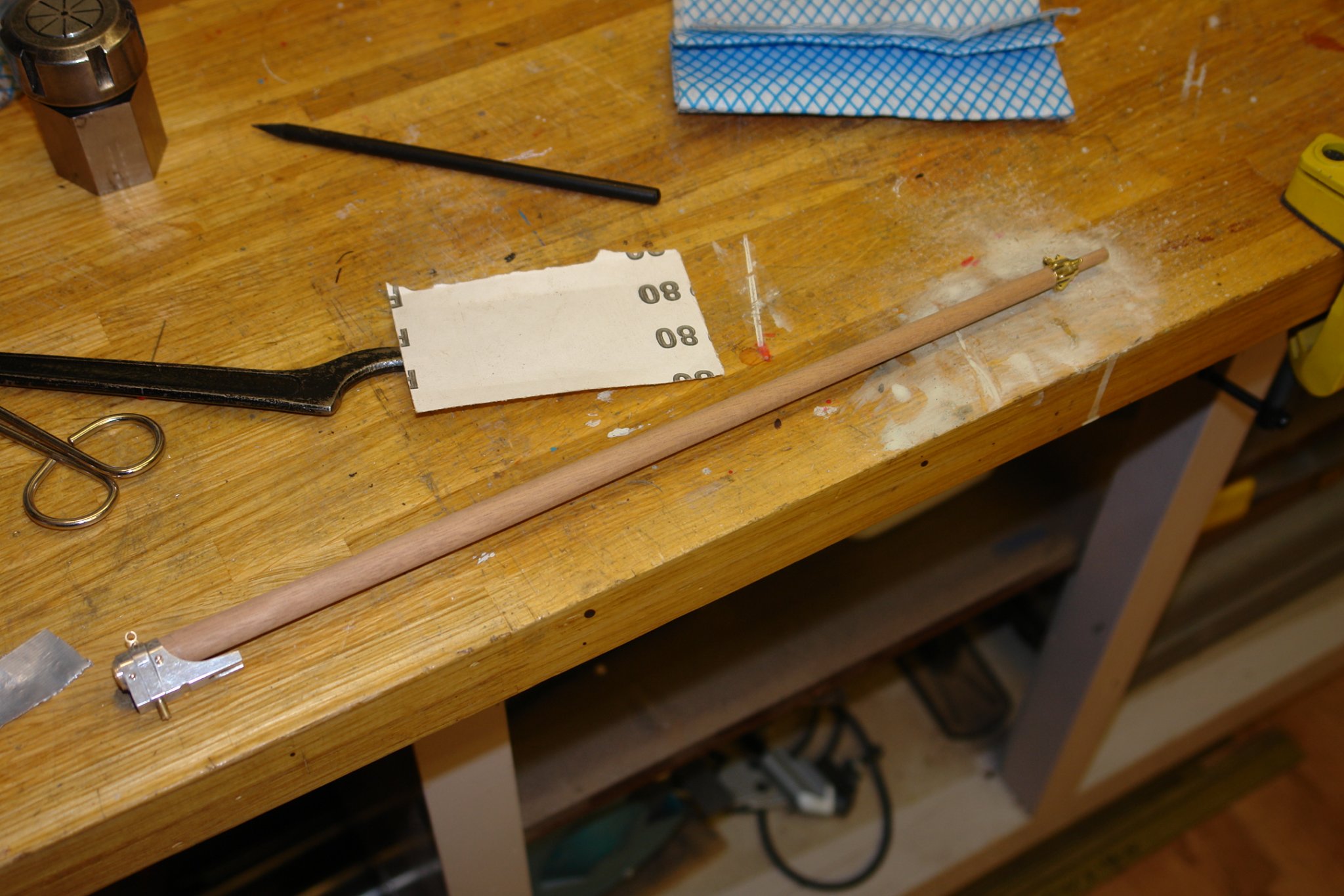
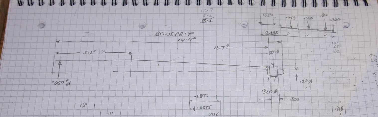
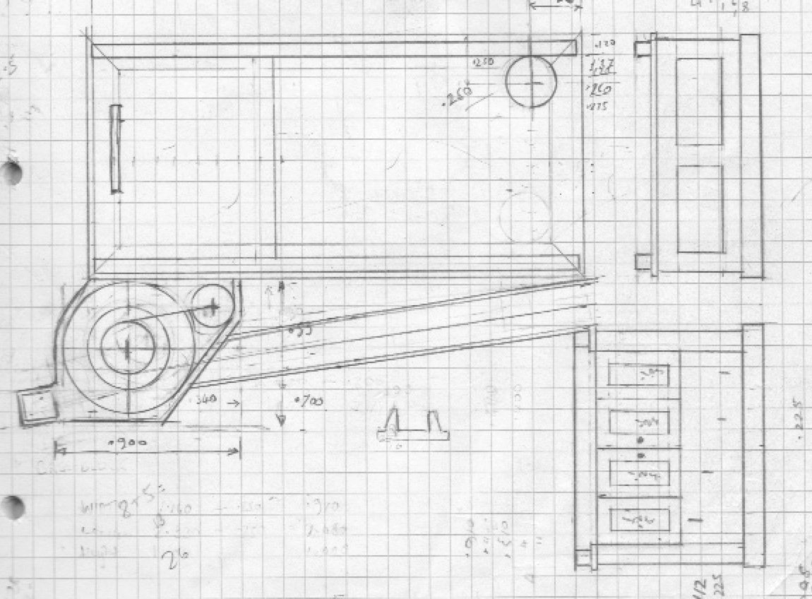
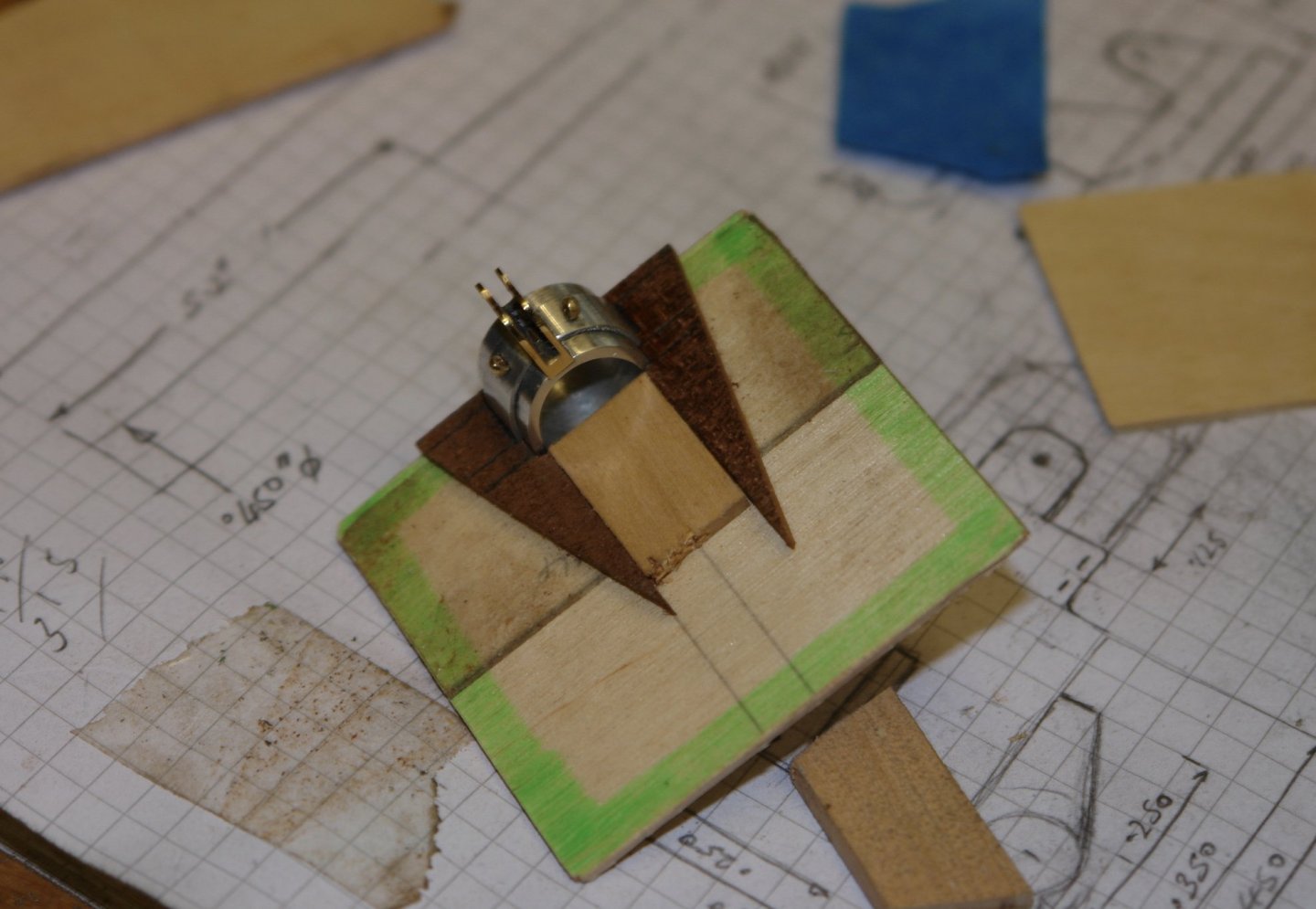
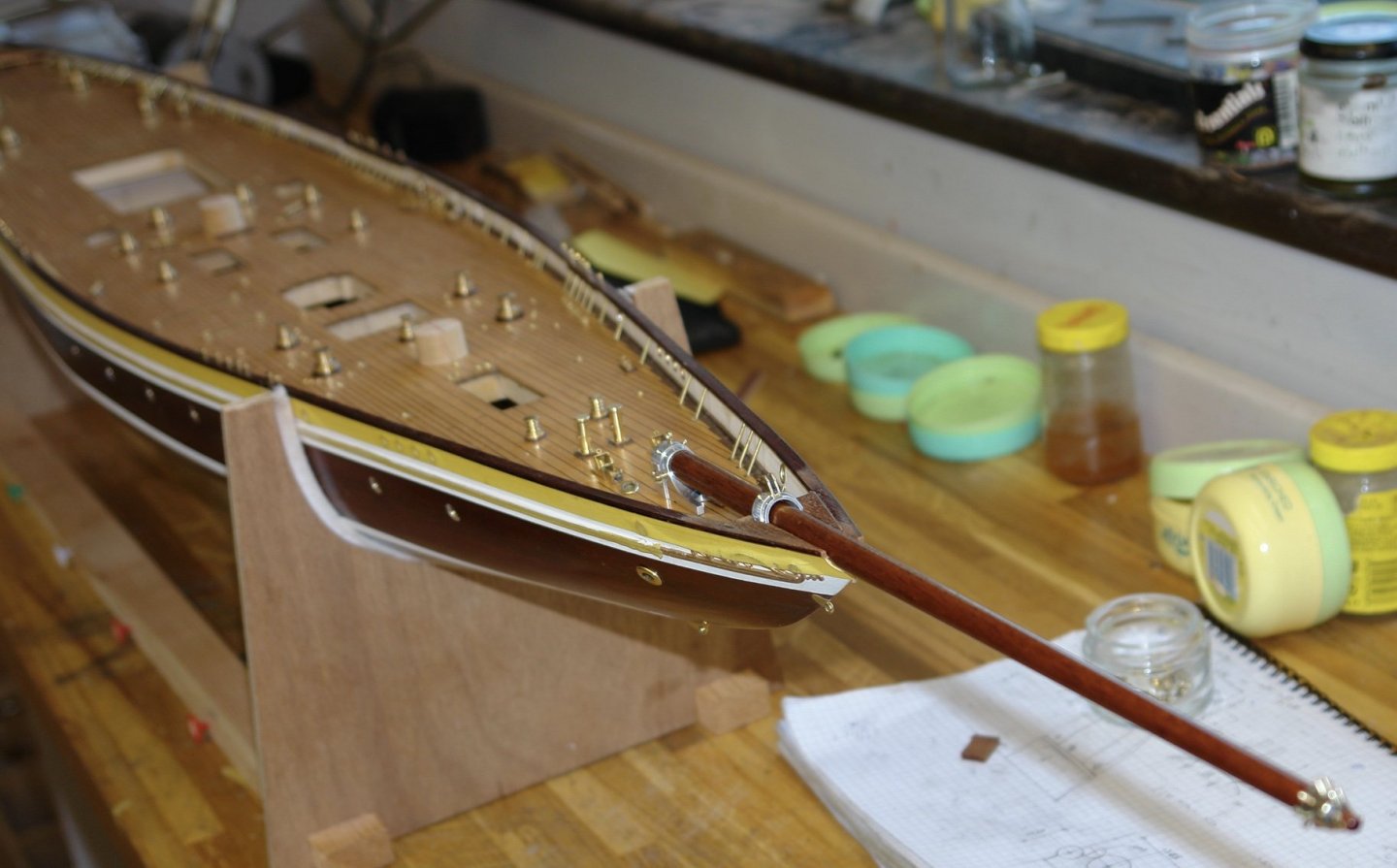
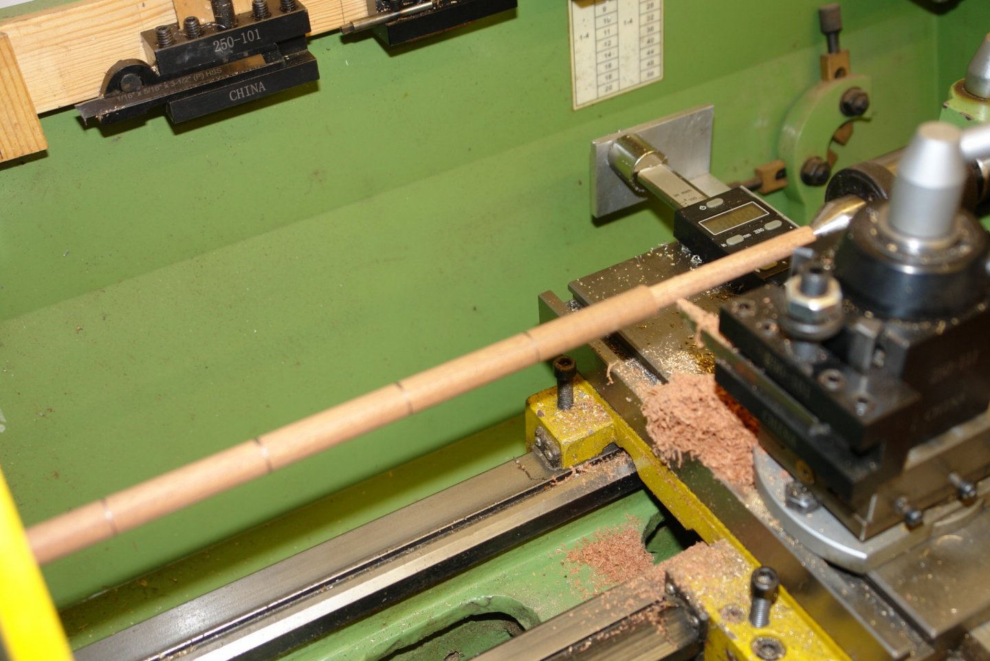
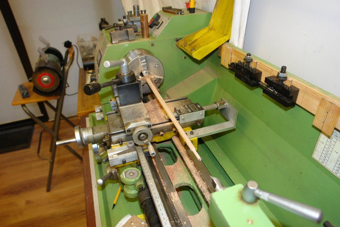
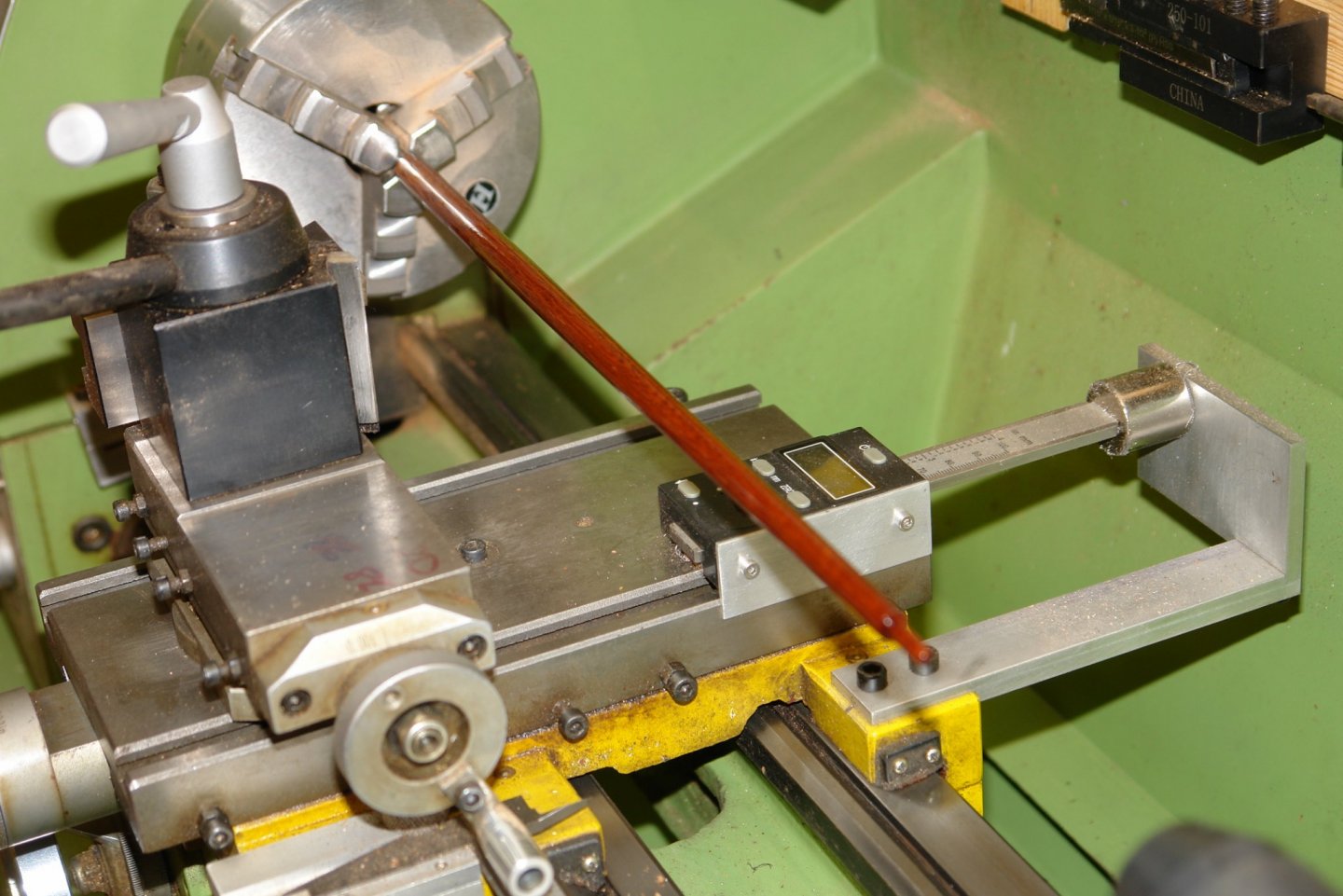
Having made the cranse iron the next logical step was to make the bowsprit. The bowsprit is some 14 inches long with the first third parallel at .450" diameter. The second 2/3 tapers gradually down to a diameter of .320". I had a piece of .5" diameter sapele left over from my previous build and I turned this on the lathe as a series of cylinders of reducing diameters (see top right hand corner of sketch below). With a slender turning of this type it is often necessary to use a fixed steady (a moving steady can't be used when taper turning). Anyway I decided to improvise by using my cupped hand as a steady and this worked remarkably well but but the friction made my hand quite hot - in reality too hot. Having turned the series of parallel diameters I smoothes out the steps with sandpaper to get a smooth taper. The large end was then bored to take the shaft on the foot and the narrow end was turned to match the bore of the cranse. I painted the bowsprit with poly while rotating it at low speed on the lathe.


-
ancre La Salamandre by tadheus - 1:24
KeithAug replied to tadheus's topic in - Build logs for subjects built 1751 - 1800
Nice to see more progress Pawel. -
Eberhard - very fine work as usual. I will be interested in your perspex polishing technique when the time comes.