KeithAug
-
Posts
3,986 -
Joined
-
Last visited
Content Type
Profiles
Forums
Gallery
Events
Everything posted by KeithAug
-
 I should have remembered that. But it does beg the question how she coped when one engine was being maintained. Short circular trips probably. Rigging looking like it will make for some interesting posts - looking forward to watching it develop.
- 599 replies
-
- 3
-

-
- sidewheeler
- arabia
- (and 4 more)
-
Jon - yes we are all getting more time to perfect our skills. Keep safe.
- 23 replies
-
- 1
-
-
- dancing feather
- pilot schooner
- (and 1 more)
-
Yes it worked very well, another idea to tuck away for later. She is looking very good. On a different point - I assume these vessels needed to be reasonably manoeuvrable. But with a fairly shallow draught (and rudder) I wonder how they achieved it. Could the paddle wheels turn at different speeds?
- 599 replies
-
- 5
-
-
- sidewheeler
- arabia
- (and 4 more)
-
Rob - great idea for ready use tool storage - I assume magnetic strips - must copy that. Rigging looking great also.
-
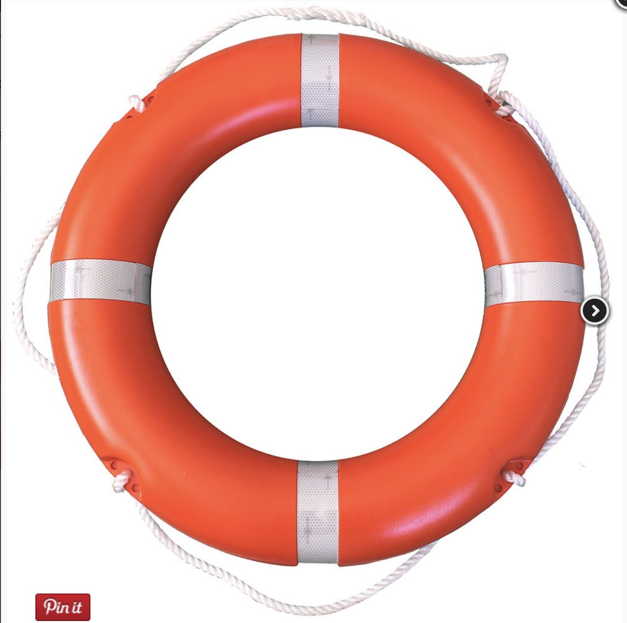
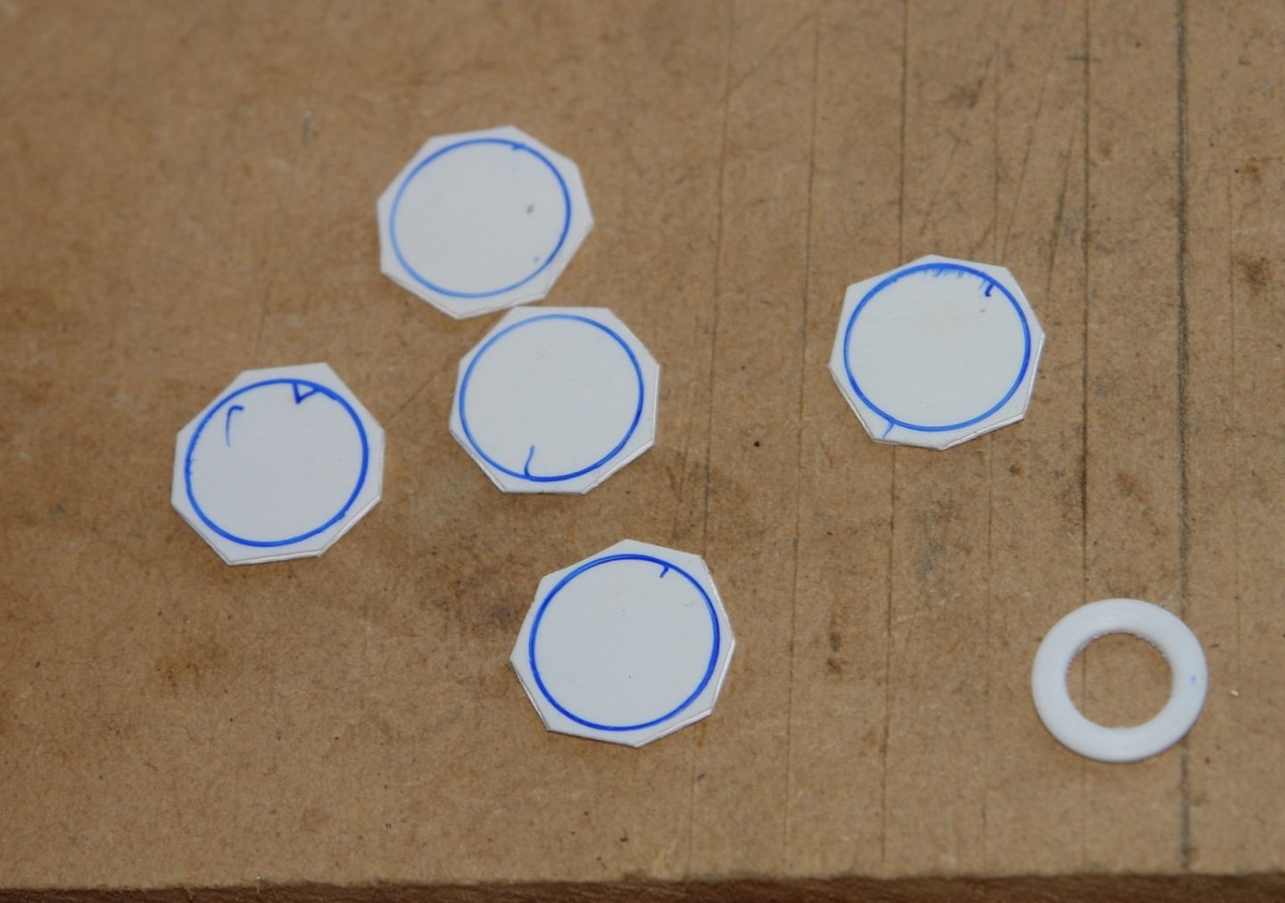
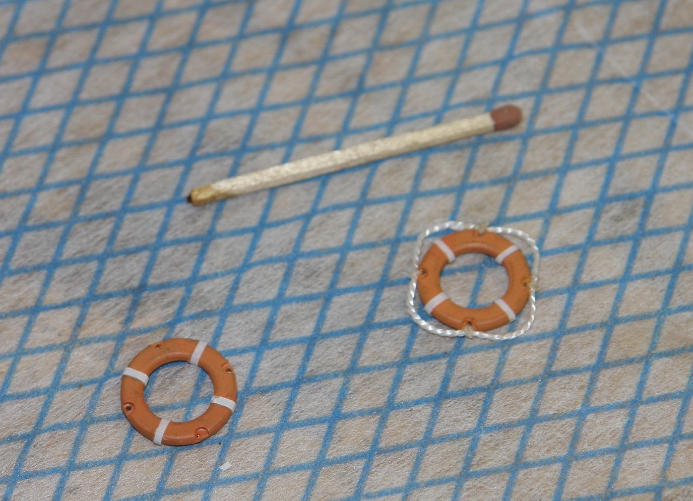
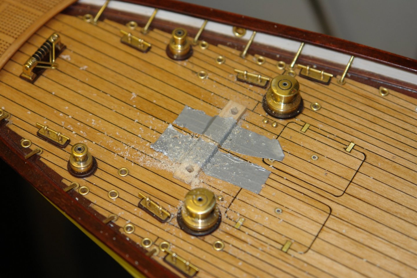
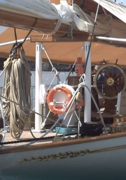
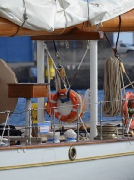
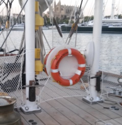
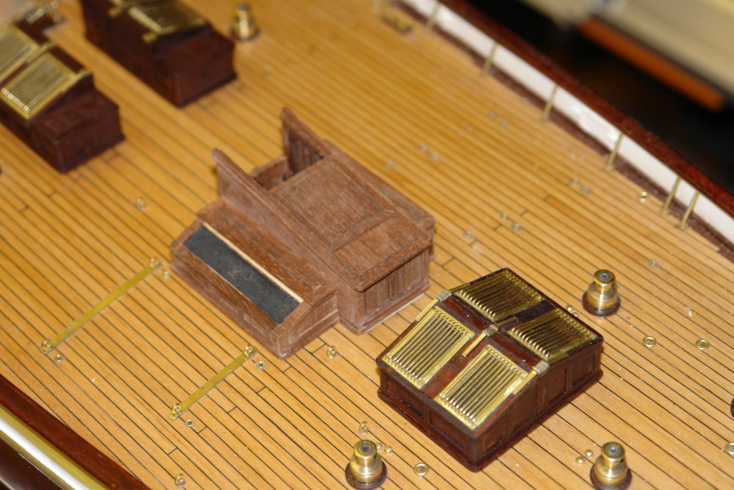
So on to the life rings - the real ones come in two standard sizes 30" and 24" outside diameter. Scaling the photographs confirmed that the ones I needed were of the 24" type or 0.66" diameter at model scale. I picked one that looked about right from the web. I made the ring from .040" thick plasticard. I cut 6 pieces but in the end only needed 4. The rings were cut to shape and profiled while attached to the end of a piece of aluminium bar. The shaping was done with a needle file while the rings were on the lathe. Four rings were made and then joined. A piece of dowel was then turned to be a push fit in the bore and this was mounted in a square collet block to allow the 4 scallops to be cut out with a .080" diameter end mill before being drilled with a .024" hole. The rings were painted and thin plastic strips were glued to form the 4 reflective strips. Finally nylon string was attached to the 4 holes. A wooden template was then used to drill the deck to take the crutch. Wooden plinths were attached above the holes. And then the two life rings were glued in place. The masking is to protect the deck from the poly applied to the plinths.


-
Mark, the very obvious "waist" in the bulwarks is really quite an interesting feature. It will be really interesting to see it planked. Do you have any idea why they did it like that?
-
You certainly seem to be cracking on. Are you planning to add sails, what I find is that it is really difficult to get sufficient tension in the forestay to counteract the pull of the jib sheet. The forestay tends to bow more than it would on a full sized vessel. I will be interested to see how you solve the problem (if you do have sails).
-
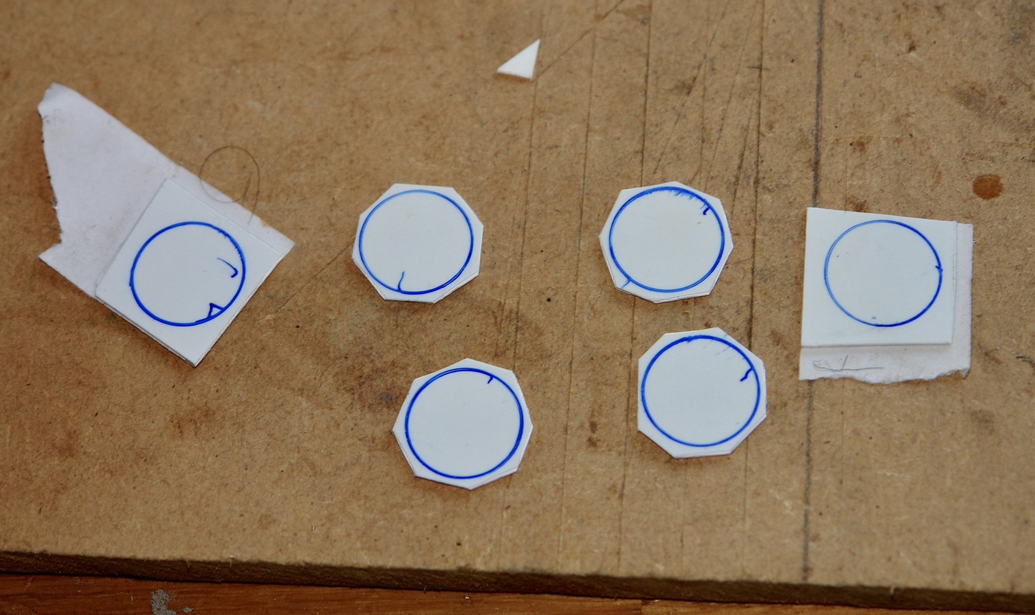
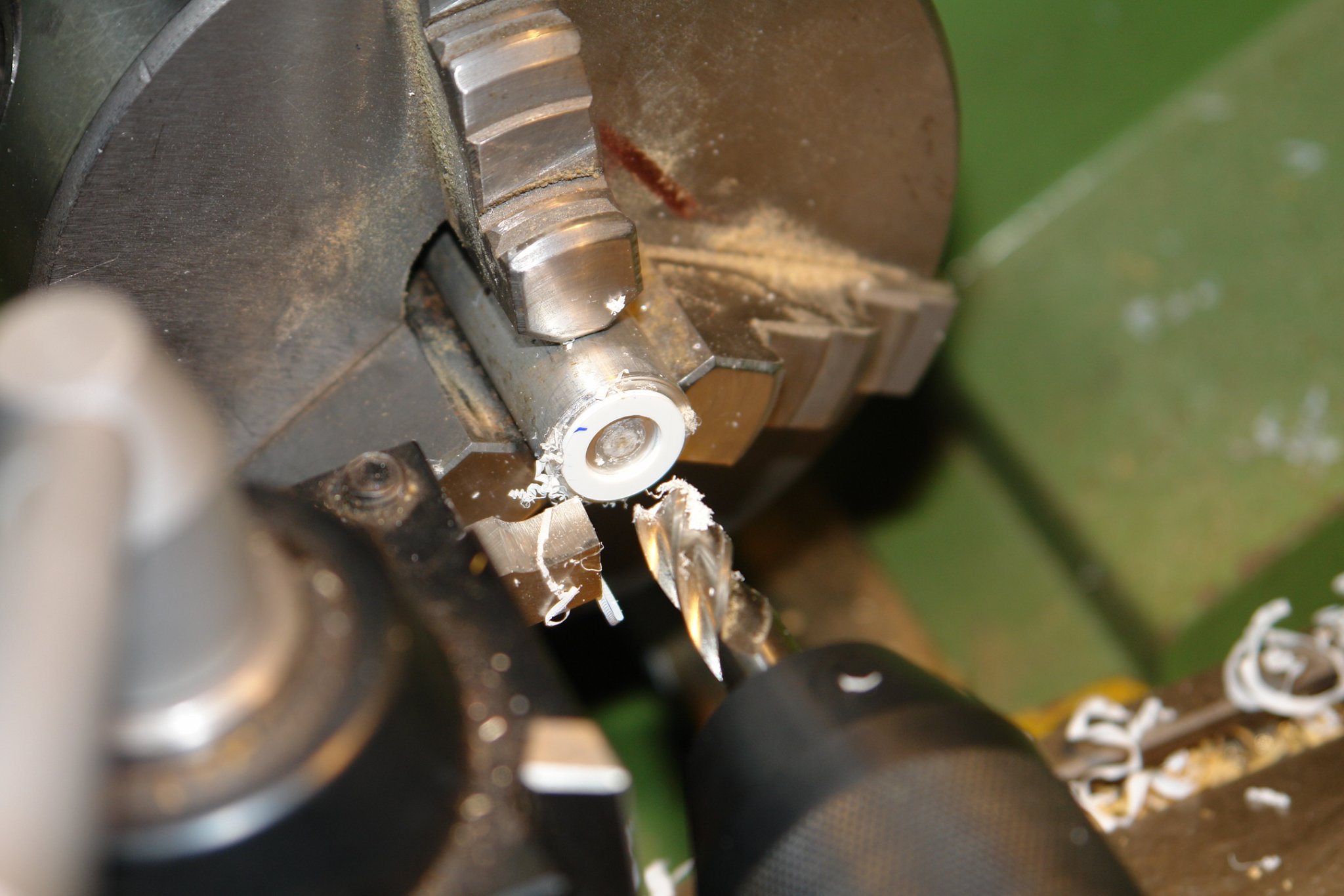
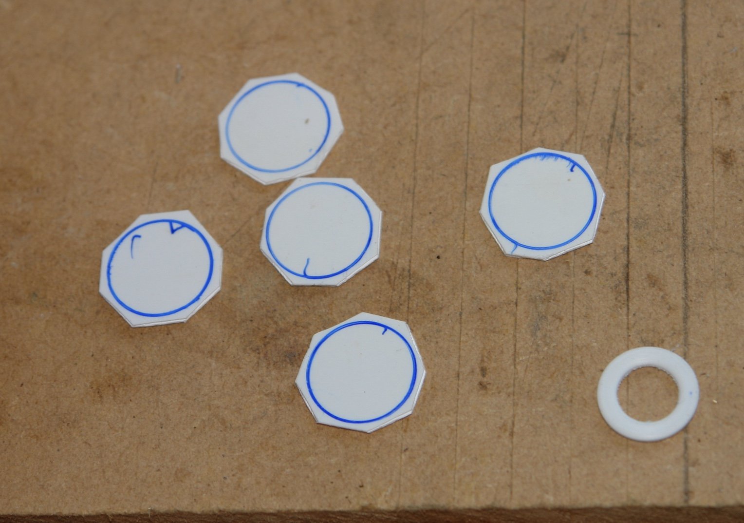
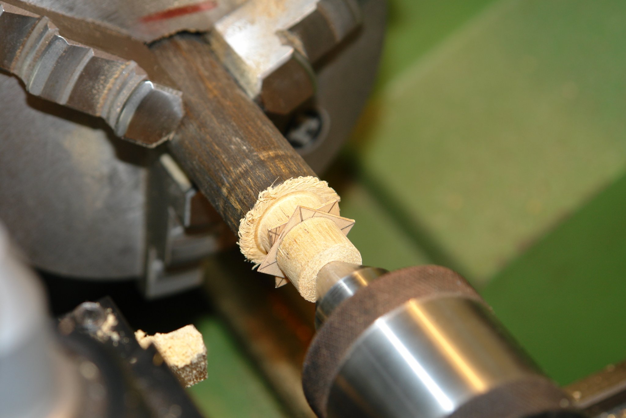
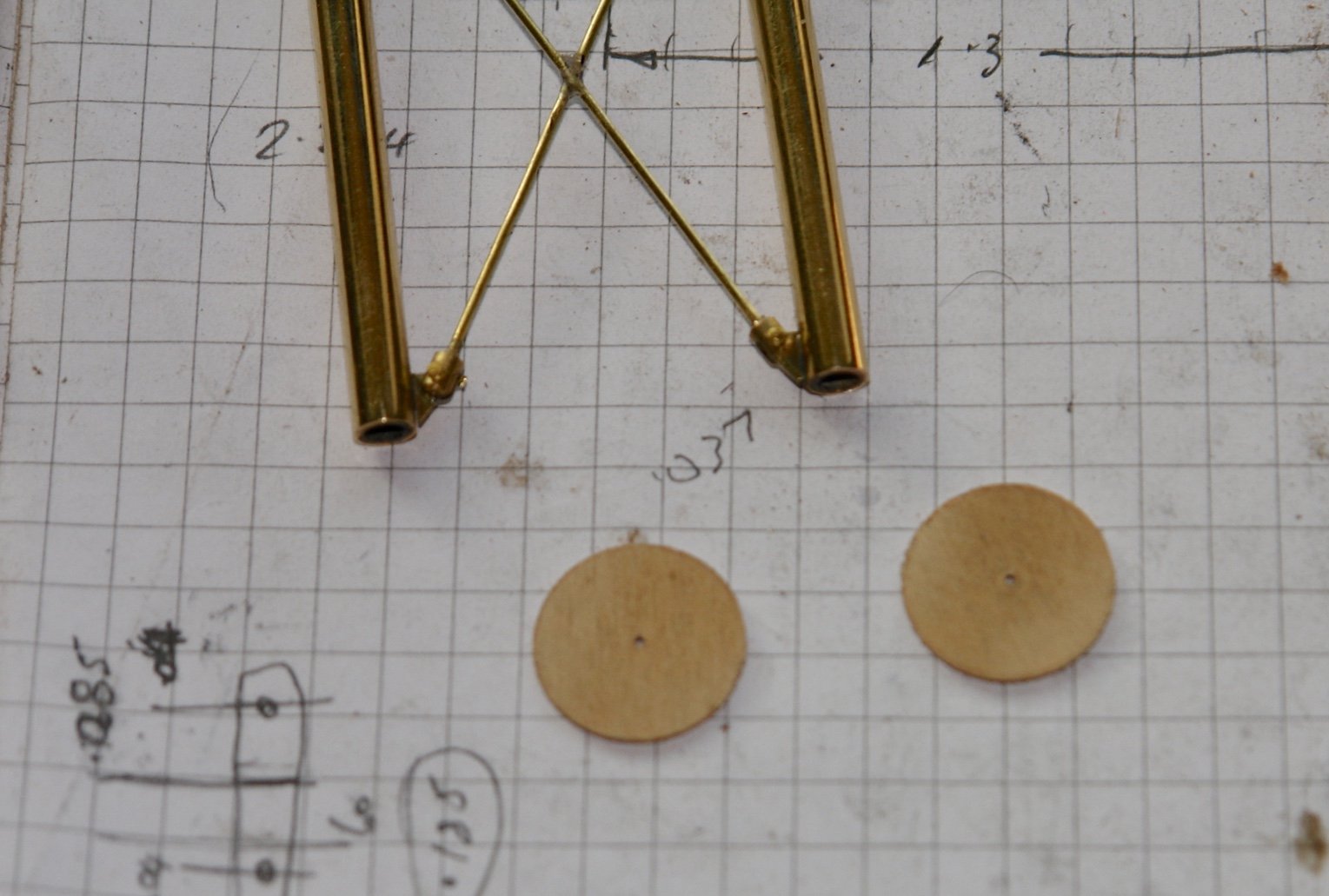
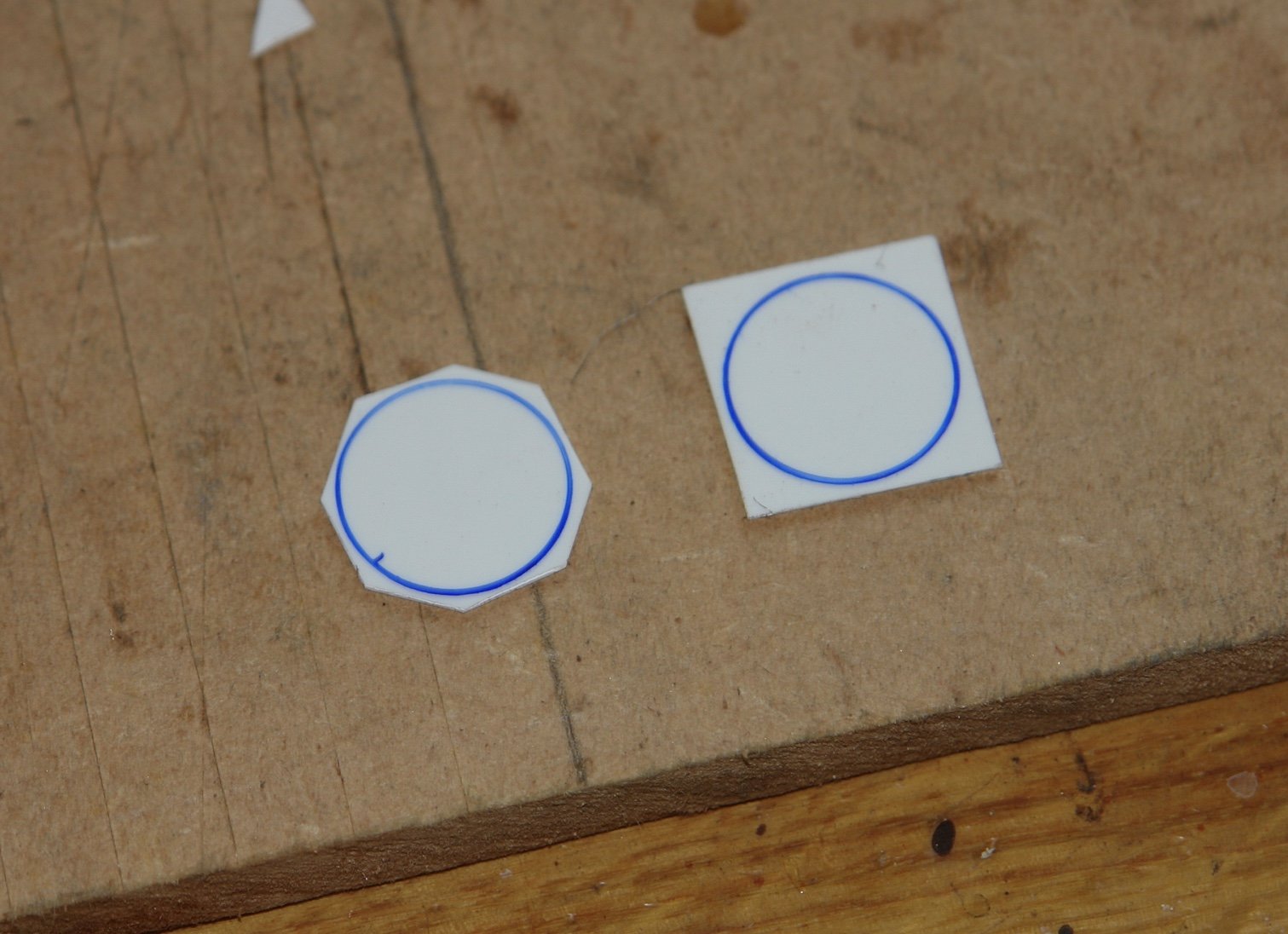
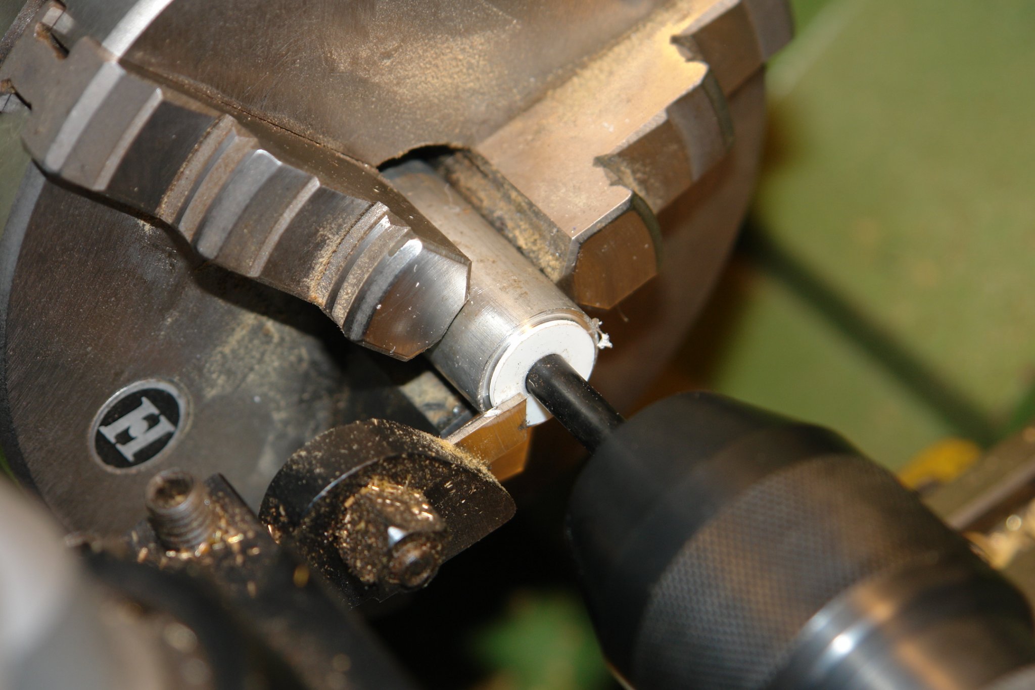
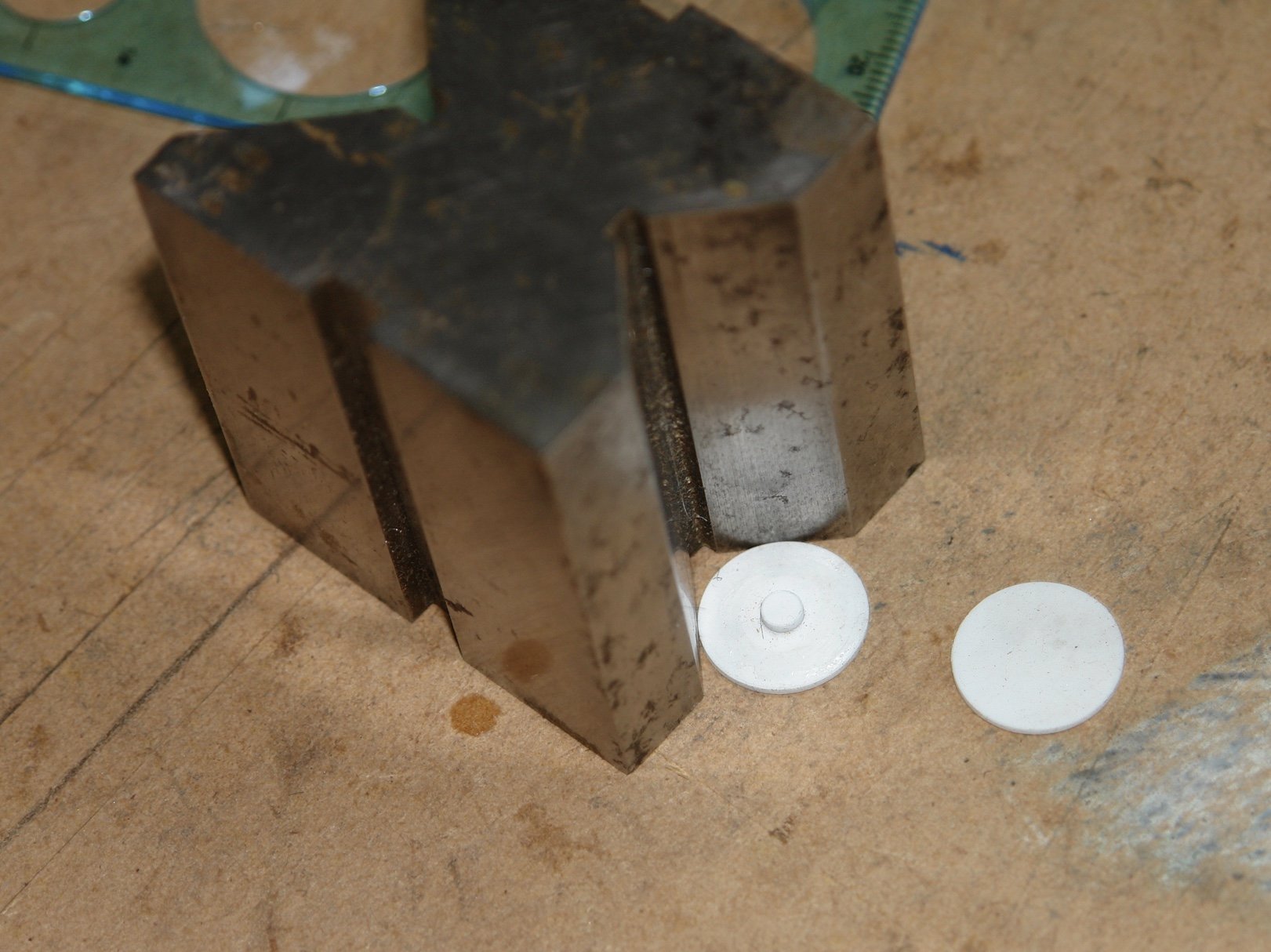
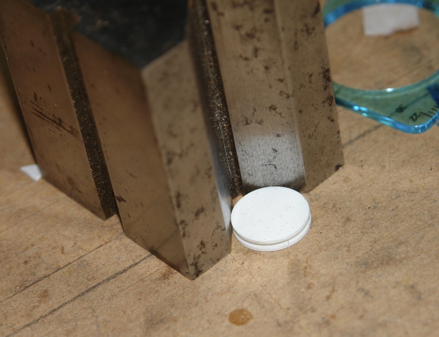
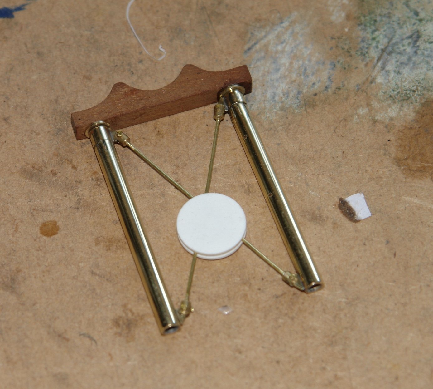
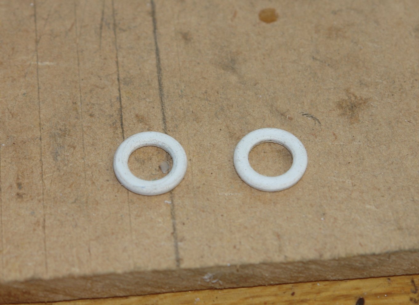
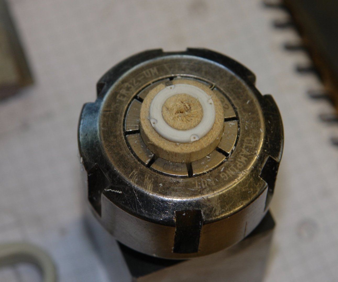
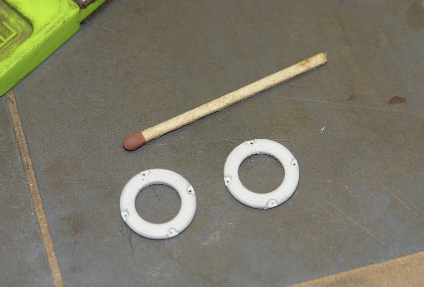
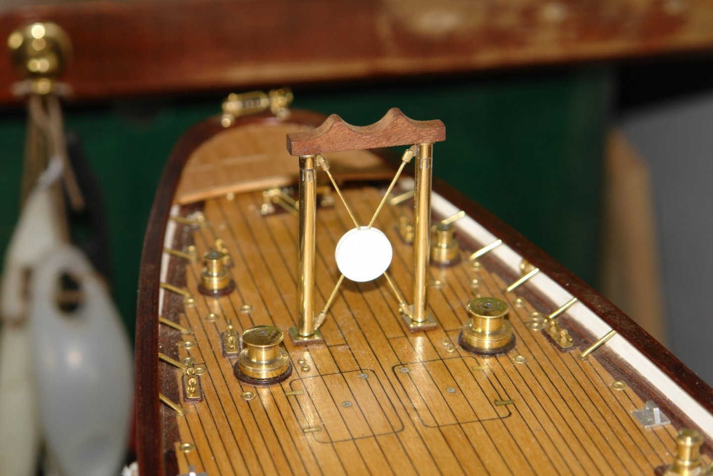
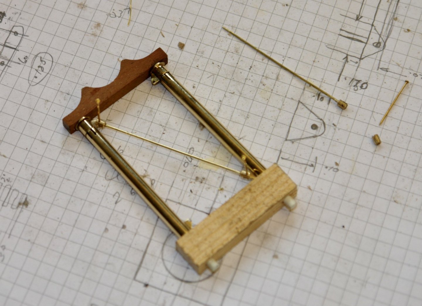
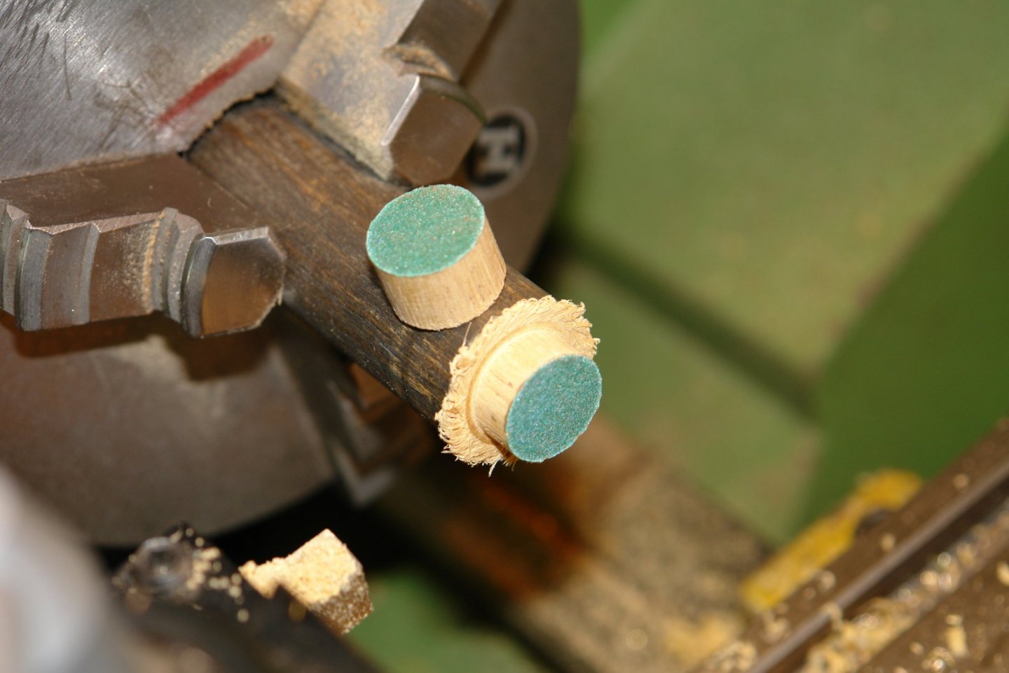
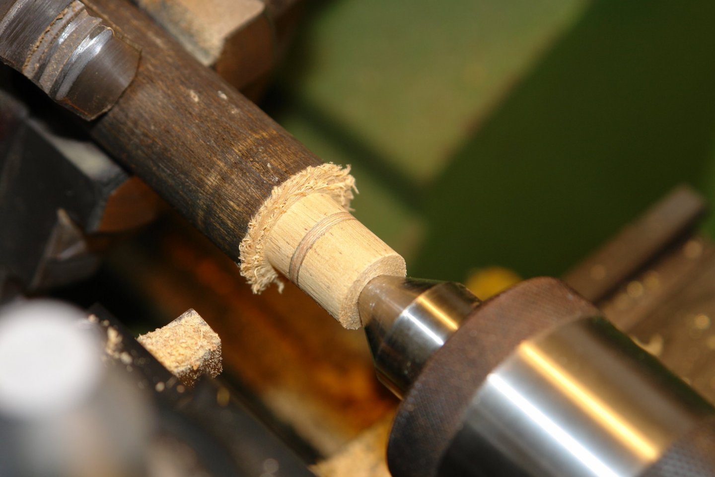
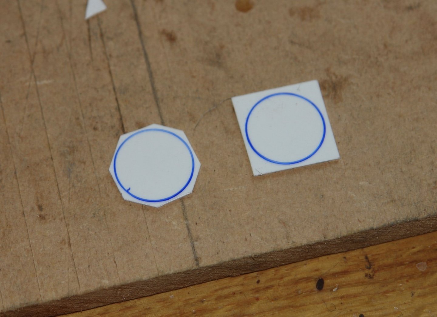
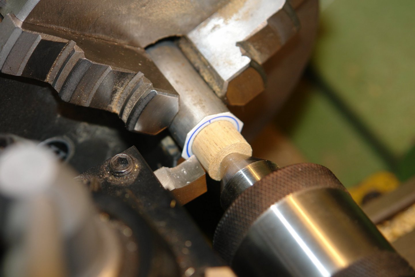
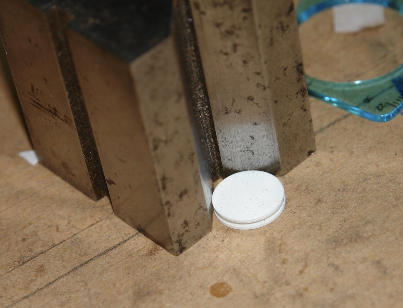
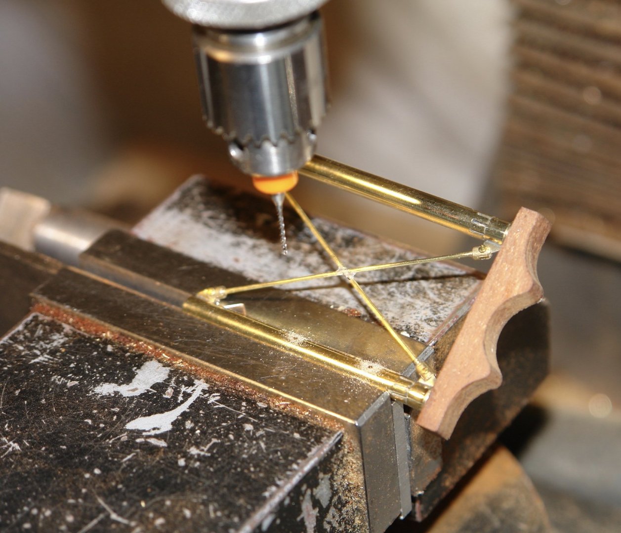
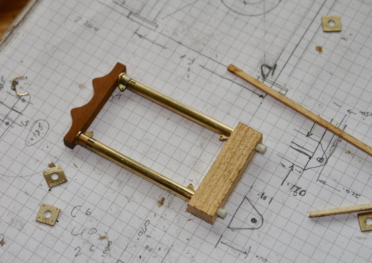
I spent some time completing the crutch. The diagonals were fitted to the pre-assembled crutch. Initially pinned in place with sewing pins while the end fittings were glued in place. Once the length was set the braces were removed and the wires were filed half through at the intersection position. The diagonals were then permanently installed with a dab of CA fixing the intersection. I then needed to make the circular plates that hold the life rings. They are 0.66" diameter and I started by making these form 1/32" ply. I turned them pressure clamped between the tailstock and lathe chuck. I started by putting a 1" dowel in the chuck and turning it down to 0.7". A section was then parted off and sandpaper was glued to the 2 flat surfaces, thus creating 2 pressure pads. Two 1" square 1/32" ply sheets were then clamped between the pressure pads using the tailstock to apply the clamping pressure. The pressure pads and the ply sheets were then turned down to the required 0.66" diameter. Having got to this stage i then changed tack and decided to make the discs out of plasticard (basically to avoid painting) The discs were turned by a similar process to that described with the exception that I used a piece of aluminium in the chuck. I also glued on and turned a central boss to form a spacer. The "v" block provided the alignment while the 2 discs were glued together. At his stage I also drilled .025" holes in the starboard column of the crutch to take the life buoy lights. Finally I glued in place the lifebuoy mounting plates.


-
Mark - I had also wondered whether they were used as vents - but had no idea what for. You may be correct in your suggestion of use.
-
love your attention to detail. working under water isn't something I have tried out but must give it a go. My guess is that the hole in the base is for a tripping line. When an anchor gets snagged it can sometimes be released by pulling it from the opposite end. During my sailing days we often rigged tripping lines particularly when anchoring over a rocky bottom.
- 81 replies
-
- 1
-
-
- egyptian
- byblos ship
- (and 1 more)
-
Just catching up Phil, so much detail, you must be very dedicated to your task.
-
Jon, at this tare you should finish it before the next millennium. do you have a target timescale?
- 23 replies
-
- 2
-
-
- dancing feather
- pilot schooner
- (and 1 more)
-
I know what you mean, the more light I put in the more I need, I think the main problem is my eyes. The blocks and shackles look really nice - worth the effort.
-
I like this option best, but of course it all comes down to the choice of the household. When I get stuck I ask the eventual owner ( my daughter ) what she thinks and go with that.
-
Beautifully accurate work and so very quick. Impressive.
- 23 replies
-
- 1
-
-
- new mexico
- battleship
- (and 1 more)
-
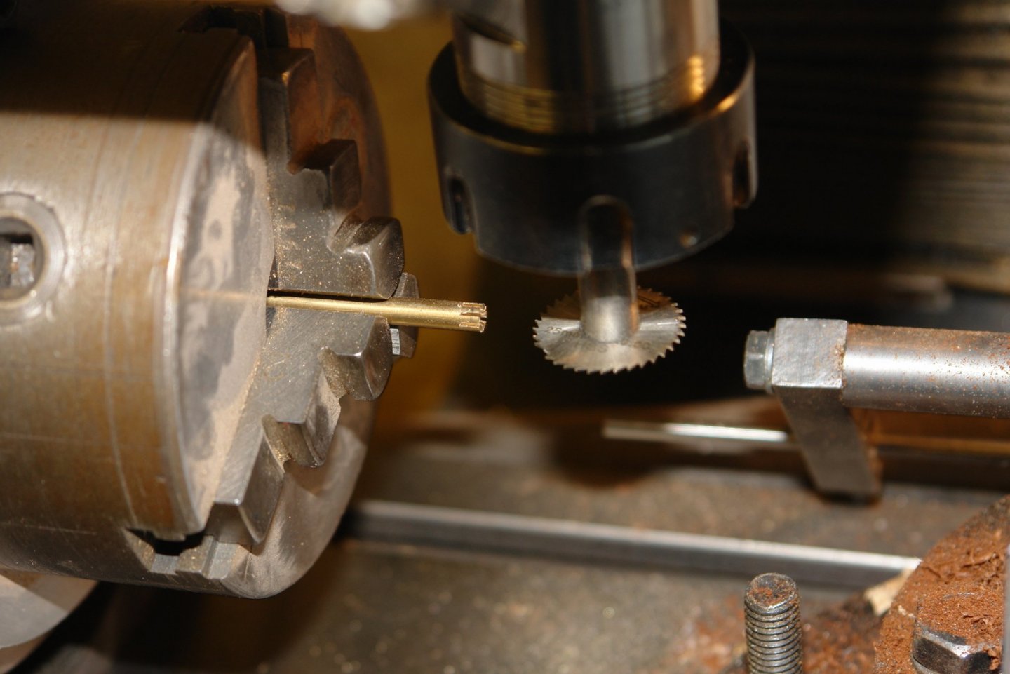
Pat, you are correct. The saw is in the mill spindle. The workpiece is in a chuck that is mounted on a rotary table, with the rotary table mounted vertically on the milling table. I should have explained better. Thank you for the feedback. druxey, thank you.
-
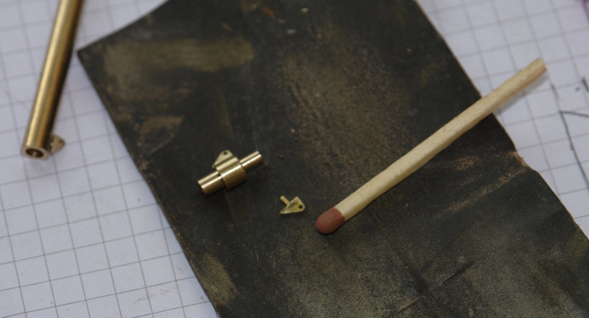
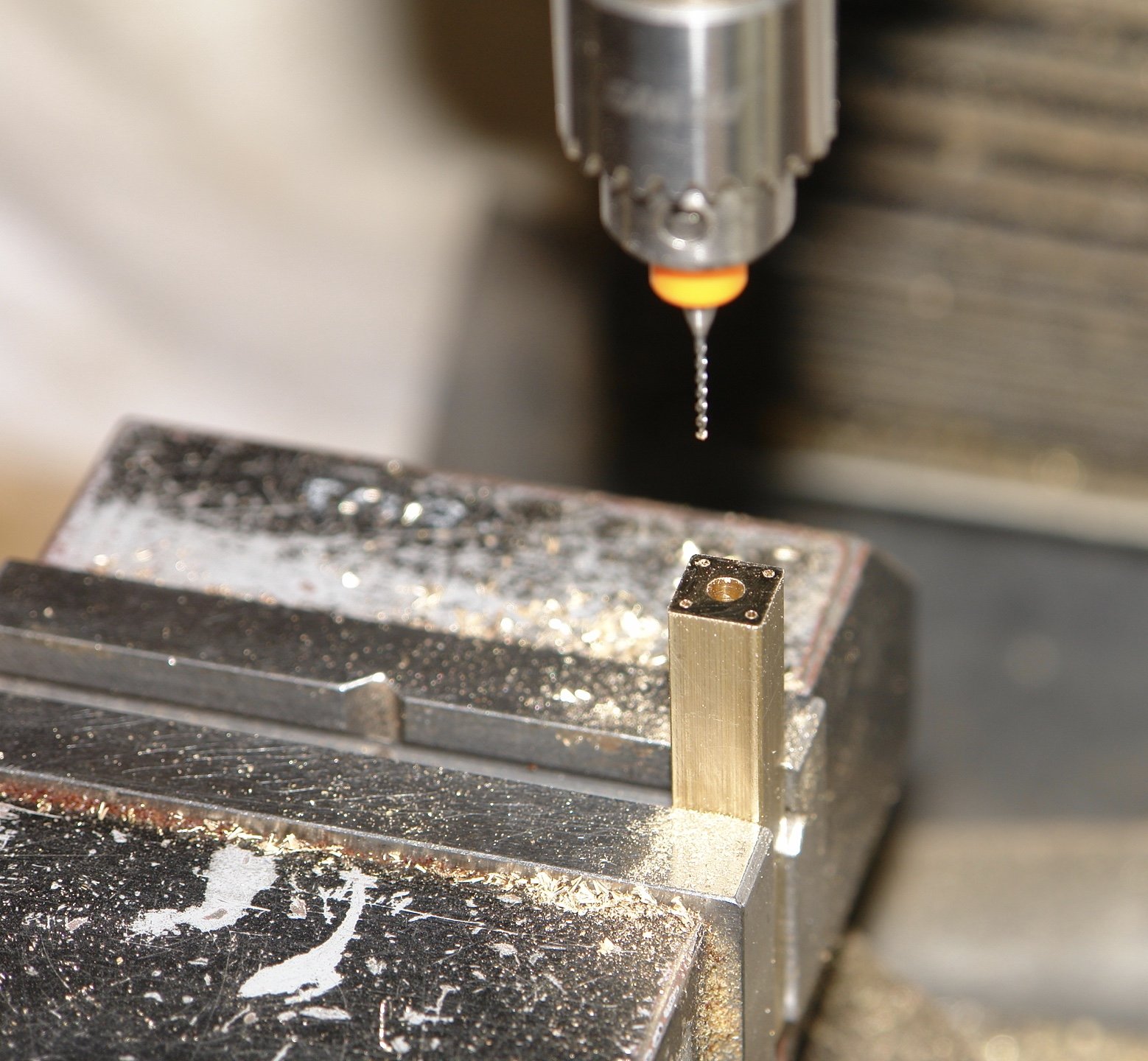
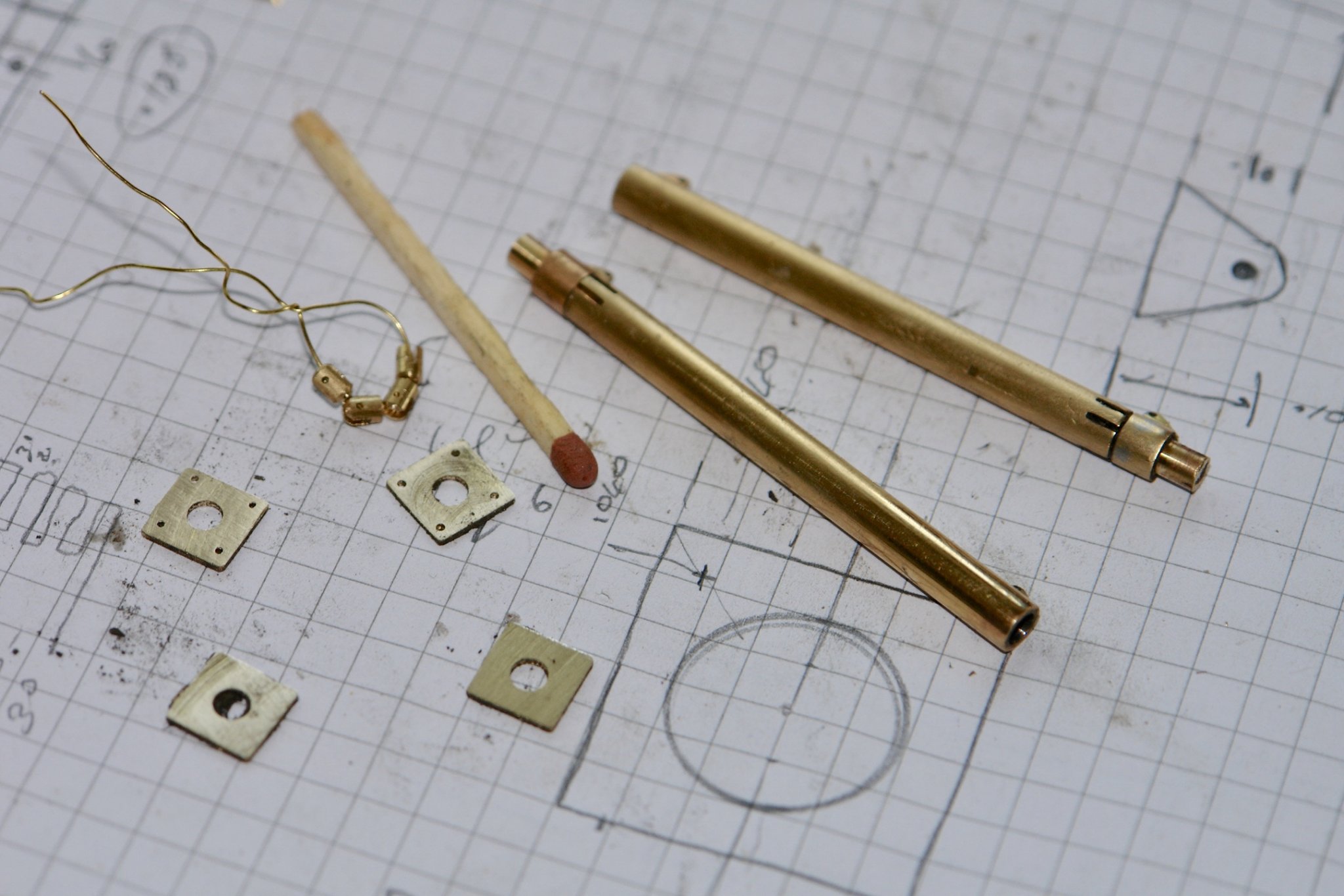
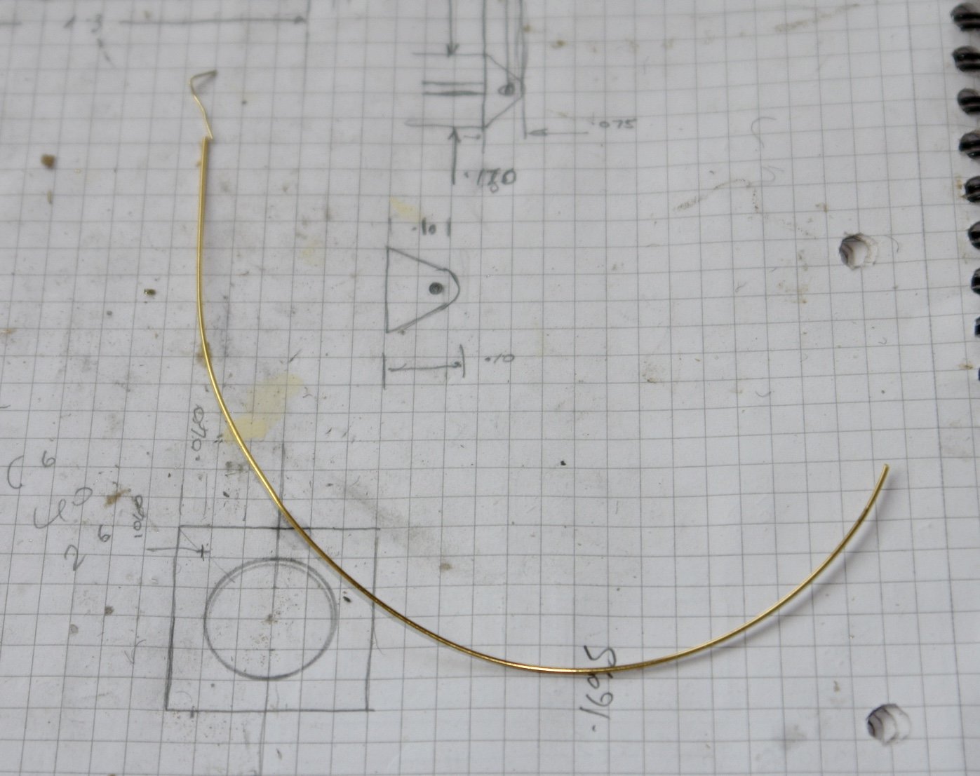
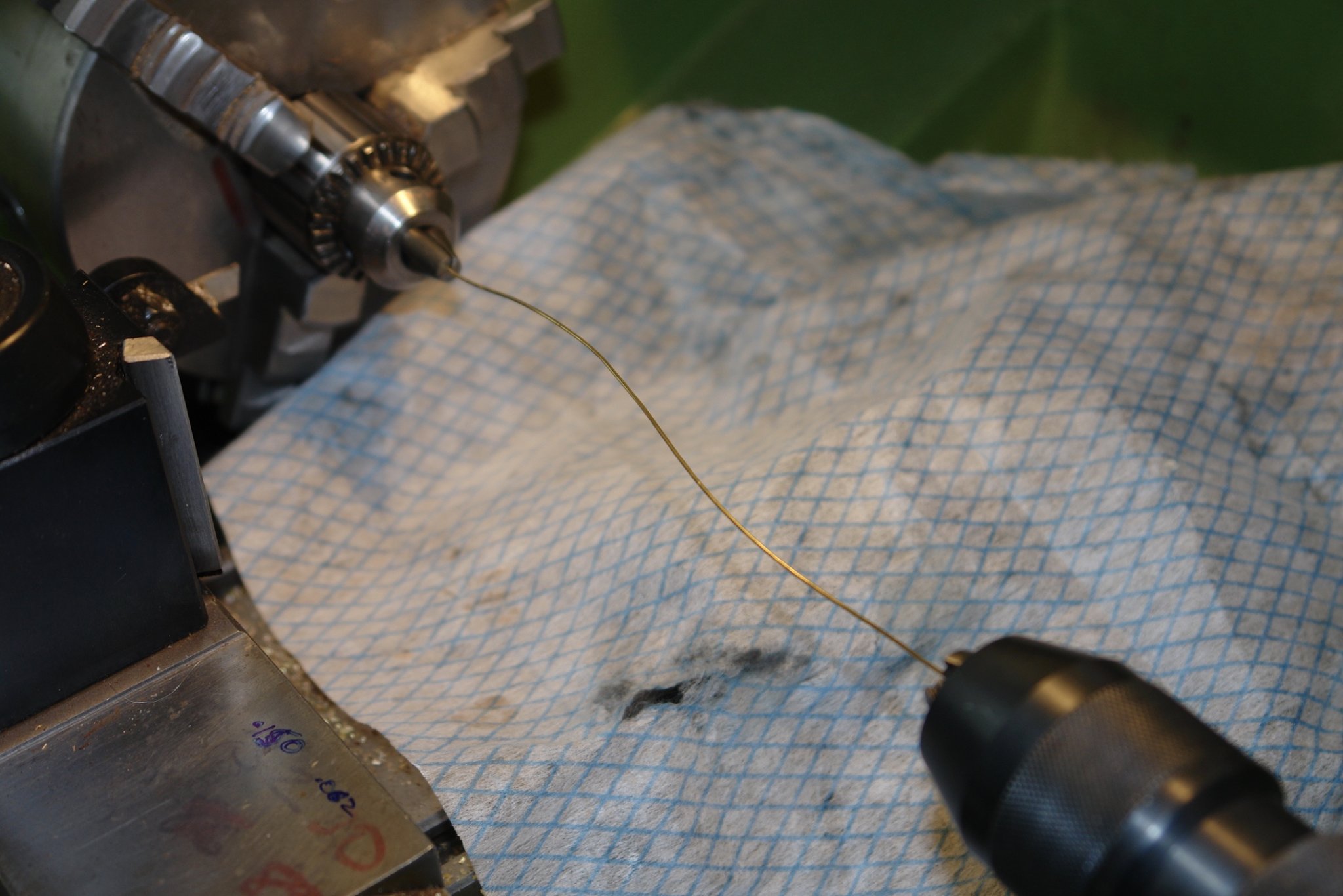
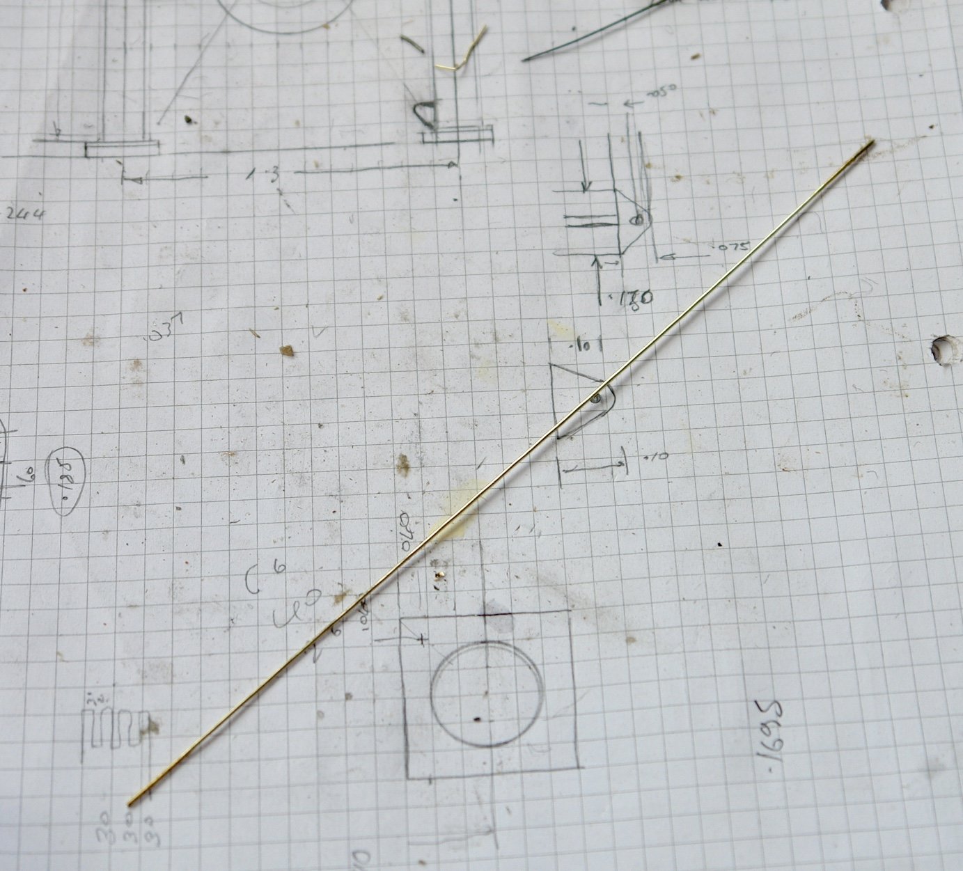
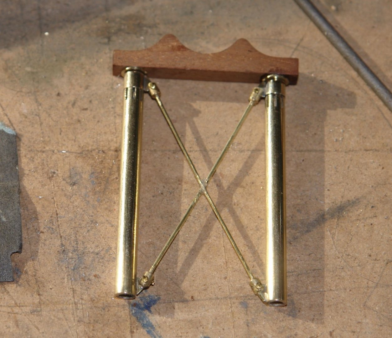
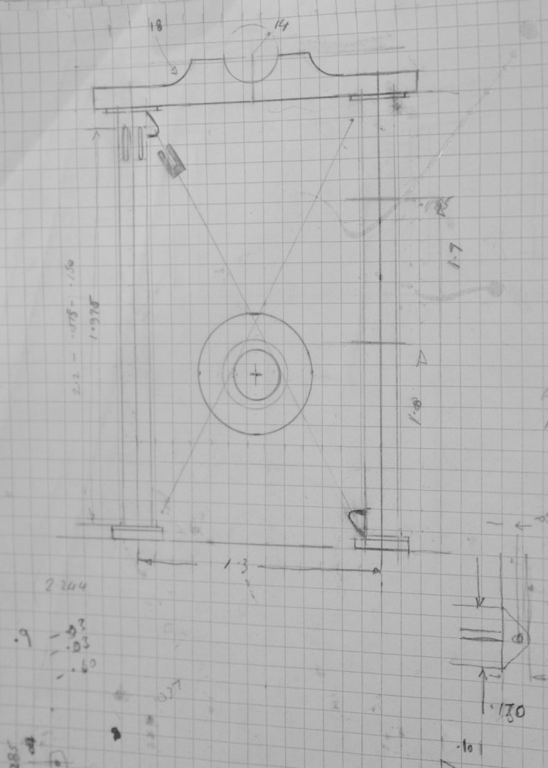
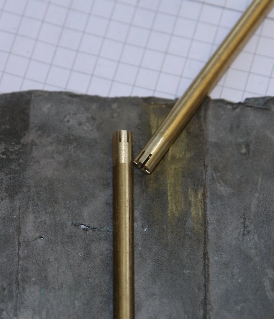
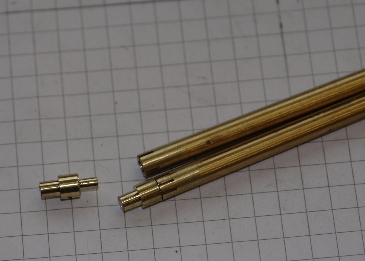
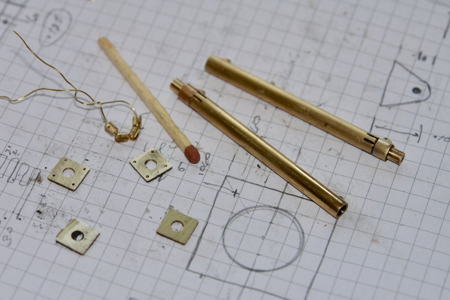
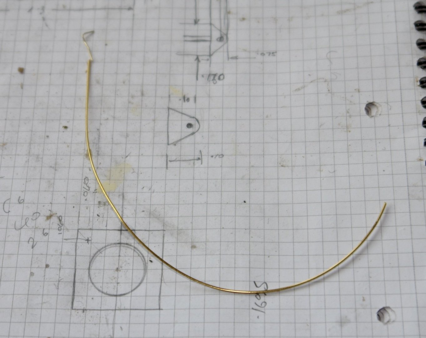
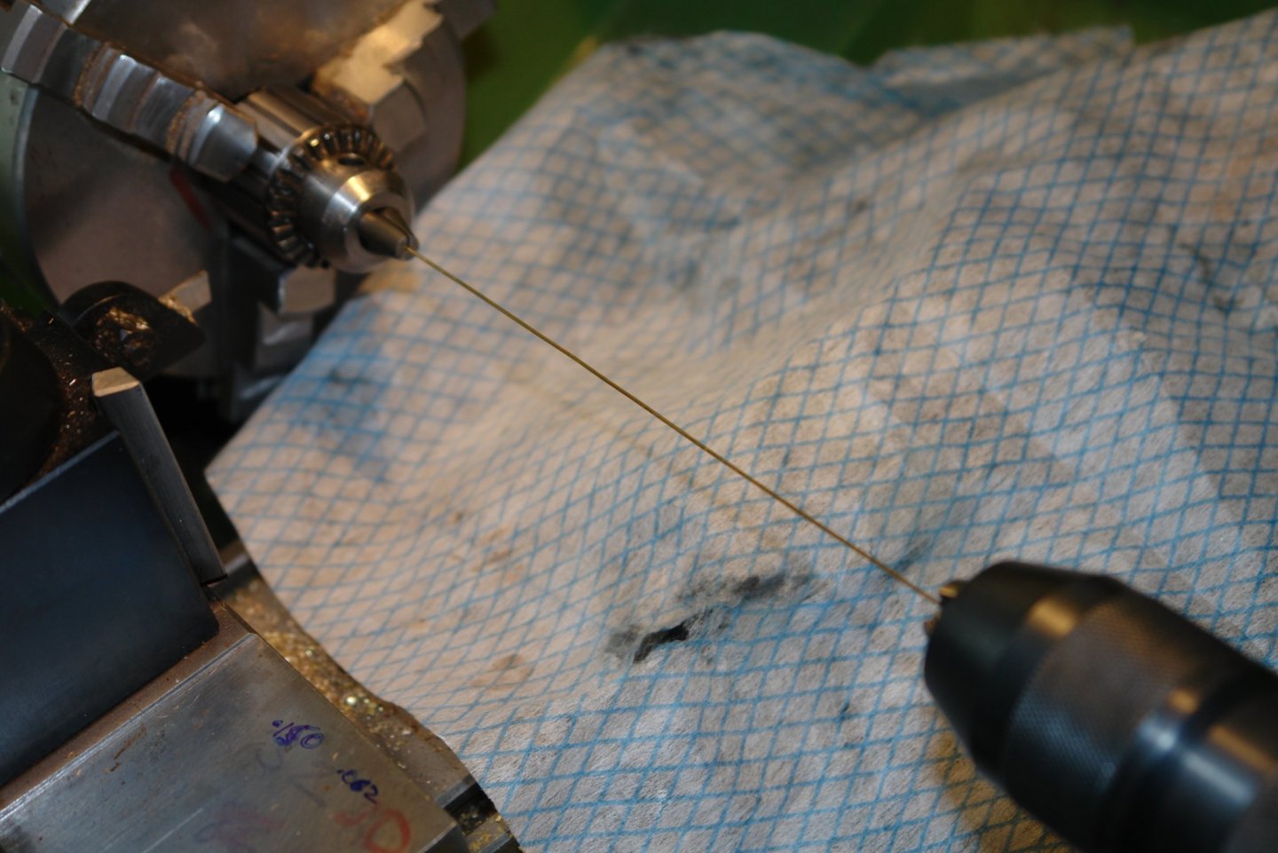
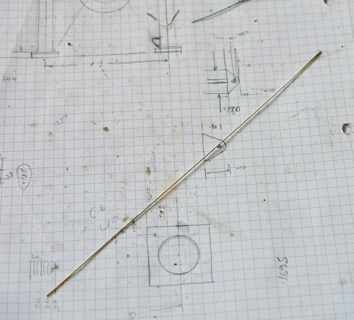
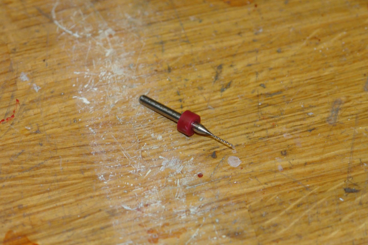
Thank you to all who have morned the passing of my drill. And so on to the main boom crutch. It is painted white but I may leave it as brass. I started with a sketch. The height and width were taken from the plans and the other dimensions were scaled from photographs. The height to the underside of the cross beam is 2.2" and centre distance between up-stands is 1.3". The life rings are of the smaller standard 24" (600mm) outside diameter. Towards the upper end of the columns are 6 slots - I am unsure as to the purpose but decided to reproduce them. The column were turned to diameter and then polished before the slots were cut with a slitting saw. I had to introduce a joint above the slots to make the slitting operation possible. In the separated top piece (above) you can see the hole (bottom edge) drilled to take the bracket for the cross bracing. The 4 bracing brackets started life as round rod. A flat end was milled on the end and then this was shaped with a file and drilled. With the shape formed the rod was taken to the lathe and the spigot was turned before the bracket was parted off. The brackets were small enough to loose - so I lost one!!!!!!!! the 4 brackets were soldered into the columns. The square flanges at the base were cut from 5/16 square bar, first drilled and then slit off. The observant among you will see 4 flanges. I though I needed 2 at the top of the columns but I didn't - the top ones turned out to be round. On the wire I have threaded 4 bosses which attach to the end of the bracing struts. These were turned from .080" rod. The cross beam was cut from mahogany and drilled to take the columns. The circular top flanges were turned from bar and parted off. The final job today was to sort out the .020" diameter wire for the cross struts. I only had soft bent brass wire but needed hard straight wire. So I used my standard straightening / work hardening method as follows:- First the wire was put in the lathe. Each end held in a Jacobs chuck - one in the tailstock and the other clamped in the lathe chuck (the lathe chuck is too large to clamp such small diameter wire). Then with the lathe to low speed I turn it on while winding out on the tailstock handle. Thus stretching and twisting the wire simultaneously. The resultant wire is both hard and straight. Goodnight and good health to you all.


-
Beautiful work on the sails Rob. I am jealous of your new tools. Where did you acquire them from?
-
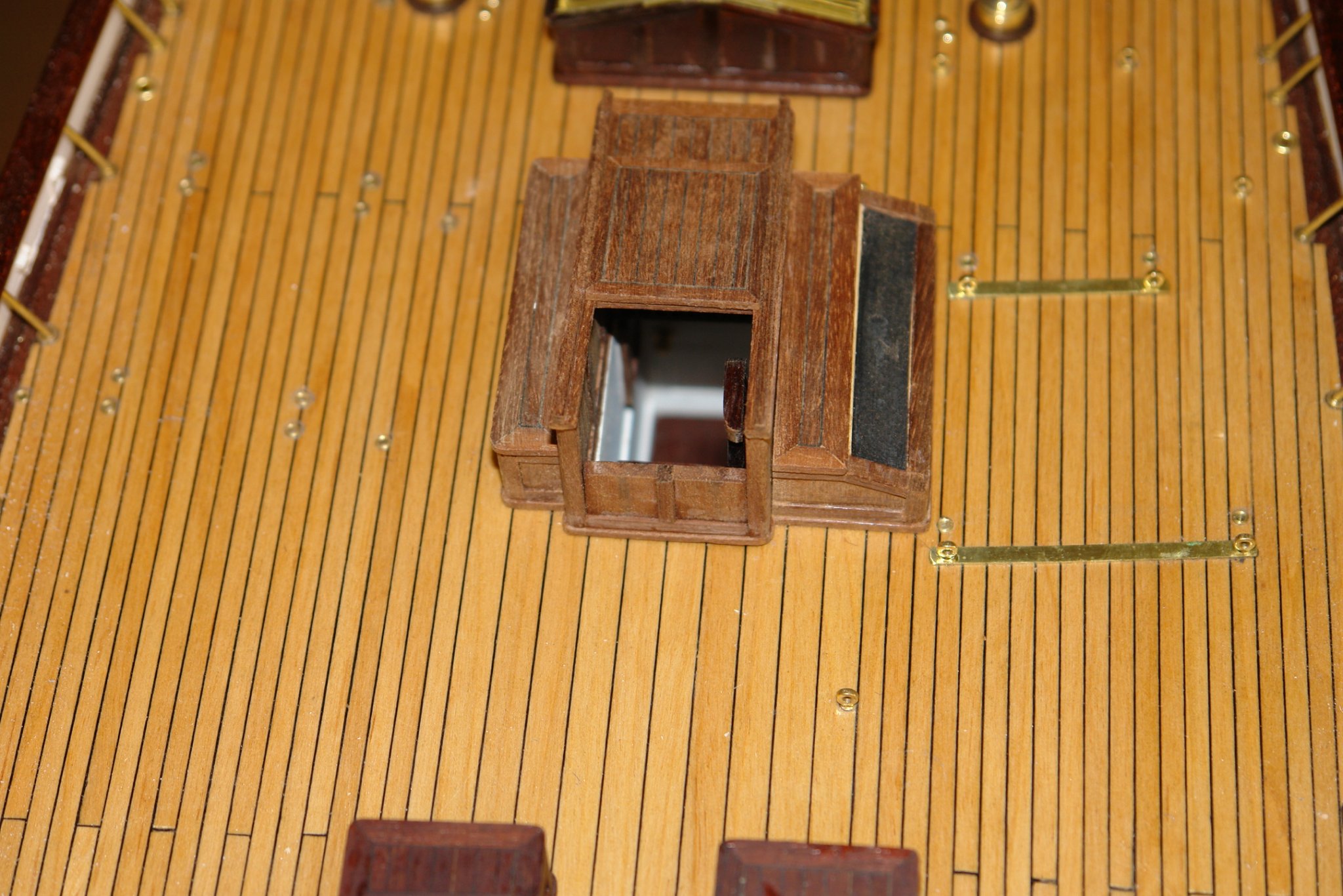
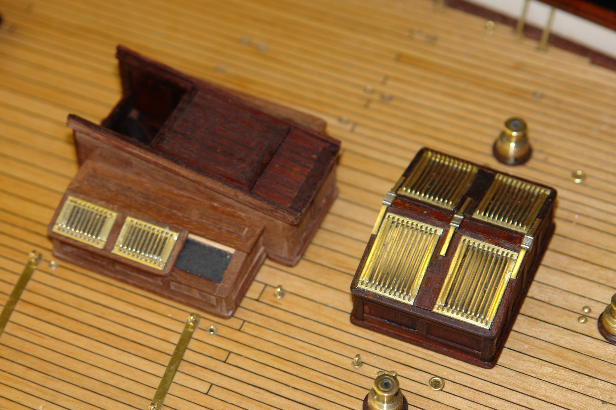
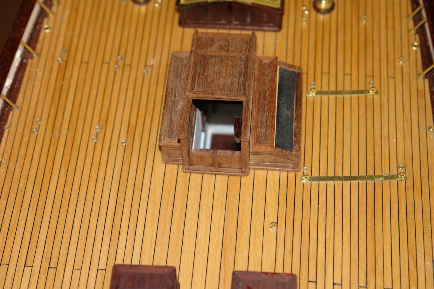
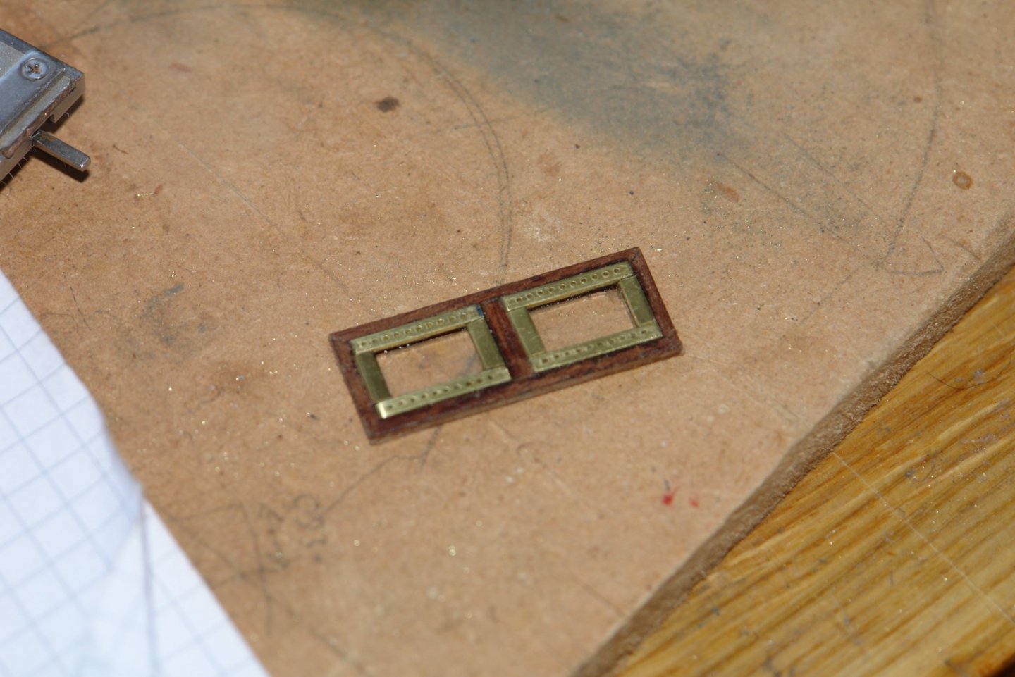
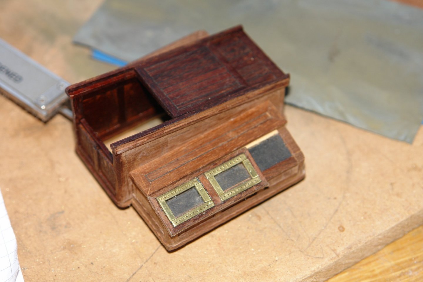
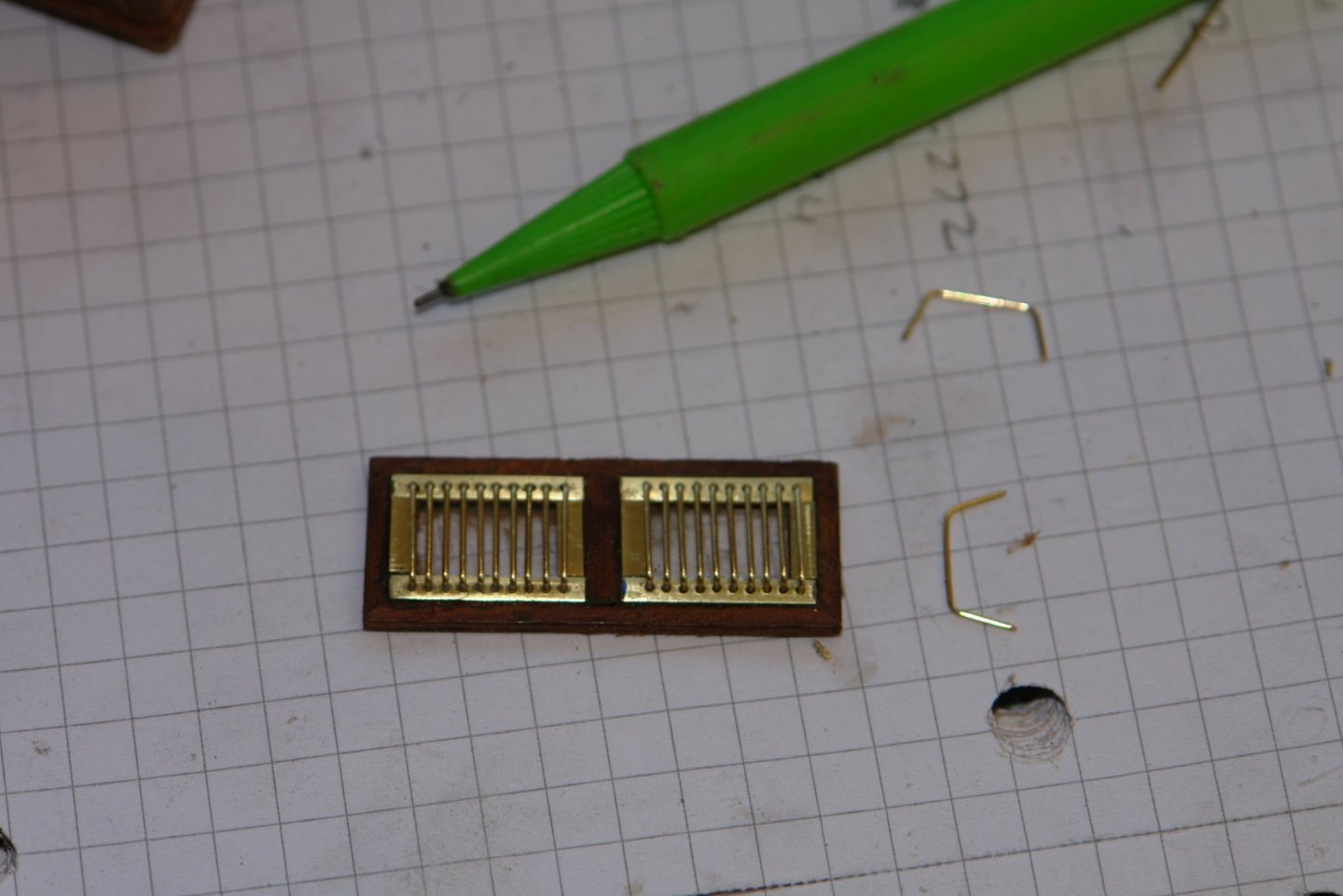
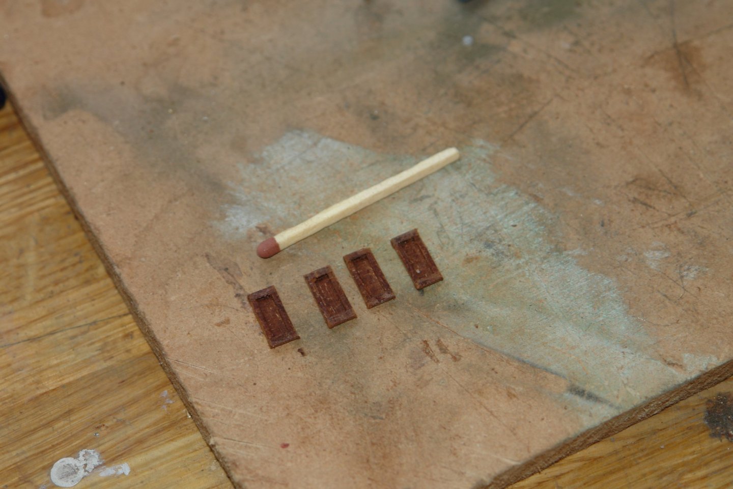
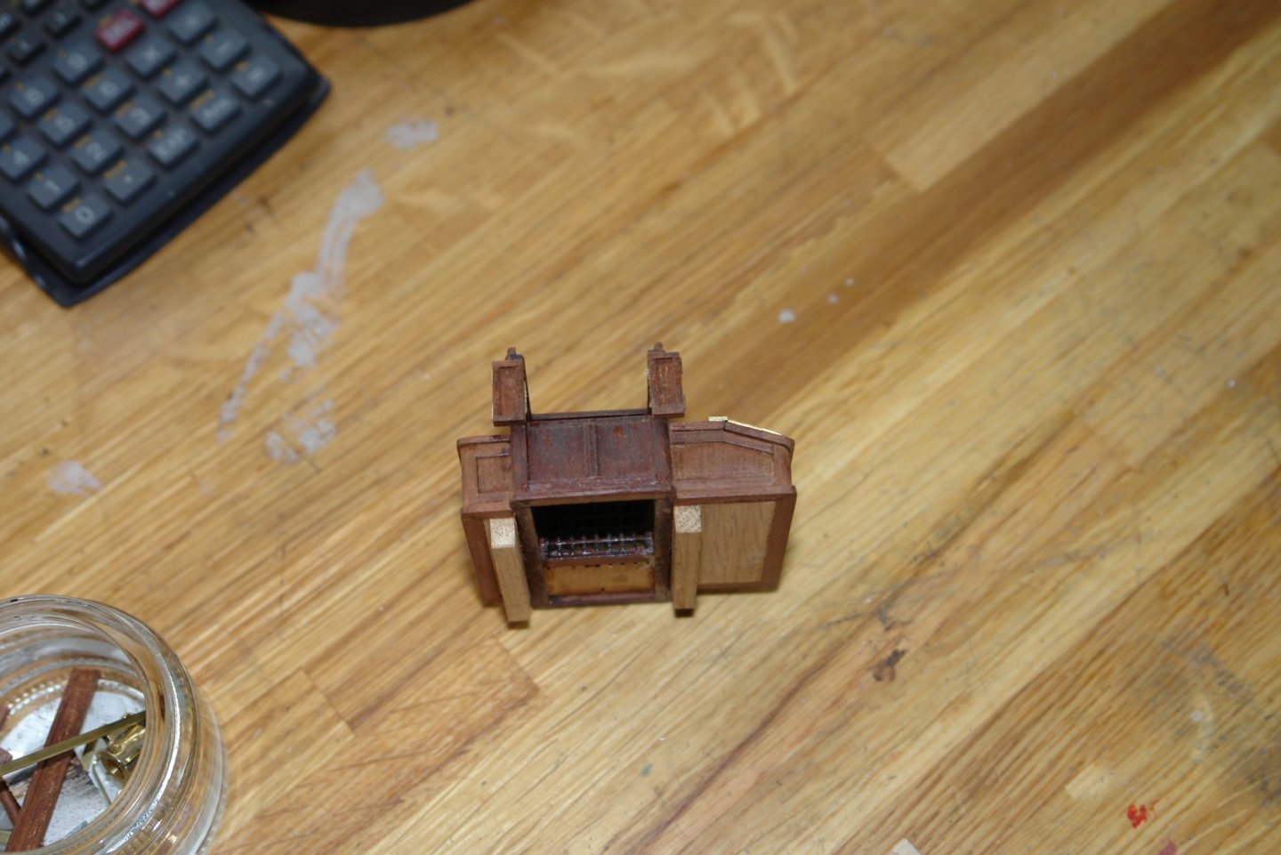
Druxey, I tried it and this is my preferred method - thank you. I used cocktail sticks reduced from .080" diameter to .070" and coloured them with felt tip pens. I completed the deckhouse (except the flags). This started with finishing the tops of the two wing structures. More skylights were required on the starboard wing but these were under half the size of those previously done. They were made in the same way as the ones previously completed. I now share the sad news of the demise of my magic 0.6mm drill bit. After it had manfully completing 224 holes I took its photograph. Two minutes later I was using it freehand to clean up another hole and the slight amount of side pressure snapped it ------- RIP. The final segment to the right of the two skylights was covered in decking planks. The bi-folding doors were then made from mahogany. They were glued in place and wire was used to simulate hinges. I feel that I need a diversion from the deckhouses and so will have a go at the main boom crutch next.

-
Javier - I think oh good another Javier build, than I open up the build log only to find it is already half built. beautiful detail but my you are quick.
-
The rope bindings are beautifully done, it is really fascinating to see how the ancient Egyptians constructed their vessels.
- 81 replies
-
- 3
-
-
- egyptian
- byblos ship
- (and 1 more)
-
Eberhard - I agree, it always feels better to make stuff like this rather than buy and then find yourself improving what you have bought. I will be interested to see how well it works.
-
Pat / Steve - I hadn't tried it. I had rolled paper around a wire but only at the required length of .15" - which was messy - but I agree a longer length cut up is a better idea. Druxey - yes good pan. I will try that first.